

Page 1
Software Version 3.20
Page 2
EMC COMPLIANCE
This product is approved for use in Europe and Australia/New Zealand
and conforms to the following standards:
European Norms
EN 55103-1 AS/NZS 4251.1
EN 55103-2 AS/NZS 4252.1
EN 60950 AS/NZS 3260
During immunity testing, this product operated according to the above standards with no
degraded performance levels or permissible performance losses.
This product is intended to be used in environment E2: Commercial and Light Industry.
Peak inrush current at switch-on has been determined at 9 amps for 1 mains half-cycle (10
milliseconds).
To ensure continued compliance with EMC Directive 89/336 and the Australian
Radiocommunications Act 1992, use only high quality data cables with continuous shield, and
connectors with conductive backshells. Examples of such cables are:
DMX, MIDI, Keyboard cables: Belden 8102 100% Aluminium foil screen,
Video, Printer: Amtron FR2651 Flat round cable, woven shield.
Australian / New Zealand
Standards
65% Copper braid.
FCC STATEMENT
NOTE: This equipment has been tested and found to comply with the limits for a Class B digital
device, pursuant to Part 15 of the FCC Rules. These limits are designed to provide reasonable protection
against harmful interference in a residential installation. This equipment generates, uses and can radiate
radio frequency energy and, if not properly installed and used in accordance with the instructions, may
cause harmful interference to radio communications. However, there is no guarantee that interference
will not occur in a particular installation. If this equipment does cause harmful interference to radio or
television reception, which can be determined by turning the equipment off and on, the user is
encouraged to try to correct the interference by one or more of the following measures:
- reorient or relocate the receiving antenna;
- increase the separation between the equipment and receiver;
- connect the equipment into an outlet on a different circuit from that to which the receiver
is connected;
- consult the dealer or an experienced radio/television technician for help.
HOG Version 3.2 Operating Manual – Part No. ZMA-3600
Page 3

Copyright
Copyright © 1999 by Jands Electronics Pty Ltd and Flying Pig Systems Ltd. All Rights Reserved.
No part of this Handbook may be reproduced or transmitted in any form or by any means, electronic or mechanical, including
photocopying and recording, for any purpose (except for the training purposes described below), without the express written
permission of Jands Electronics Pty Ltd. For HOG training purposes, copies can be made and freely distributed provided
that:
1) The Handbook is not altered in any way and is copied in its entirety.
2) All copies are distributed free of charge.
3) All copies are used for no purpose other than to educate users in HOG operation.
JANDS ELECTRONICS Pty Ltd reserves the right to determine what constitutes a legitimate training purpose and to revoke
the right for anyone to duplicate this Handbook at any time.
Trademarks
The Flying Pig Systems logo, the WHOLEHOG, and the WHOLEHOG II are registered trademarks of Flying Pig Systems
Ltd. Flying Pig Systems, Autofocus, WYSIWYG, and the Hog are trademarks of Flying Pig Systems Ltd. Effects Engine is a
trademark of Flying Pig Systems Ltd..
Macintosh is a registered trademark of Apple Computer, Inc. Vari*Lite is a registered trademark and VL5 and VL6 are
trademarks of Vari*Lite, Inc. yberlight is a registered trademark of High End Systems, Inc. SuperScan is a trademark of Clay
Paky SPA. RoboScan is a trademark of Martin Professional a/s. Microsoft is a registered trademark and Windows is a
trademark of Microsoft Corporation.
Software License Notice
Your license agreement with Flying Pig Systems Ltd., which was shipped with the HOG, specifies the permitted and
prohibited uses of the desk and its accompanying software. Any unauthorised duplication or use of the HOG software in
whole or in part, in print, or in any other storage or retrieval system is forbidden.
Disclaimer
Information contained in this manual is subject to change without notice and does not represent a commitment on the part of
the vendor.
Flying Pig Systems Ltd and Jands Electronics Pty Ltd shall not be liable for any loss, or incidental or consequential damages
whatsoever arising from the use or in connection with the furnishing of this manual, or any error contained in this manual.
It is recommended that all service and repairs on this product be carried out by Jands Electronics Pty Ltd or its’ authorised
service agents.
HOG lighting consoles must only be used for the purpose they were intended by the manufacturer and in conjunction with
this operating manual.
Jands Electronics Pty Ltd cannot accept any liability whatsoever for any loss or damage caused by service, maintenance or
repair by unauthorised personnel, or by use other than that intended by the manufacturer.
Manufactured in Australia by:
Jands Electronics Pty Ltd
ACN 001 187 837
40 Kent Road,
Mascot, NSW, 2020
Australia
Telephone: +61 - 2 - 9582 - 0909
Fax: +61 - 2 - 9582 - 0999
World Wide Web: http://www.jands.com.au
email: jandsinfo@jands.com.au
Table of Contents •••• i
Page 4

Table of Contents
TABLE OF CONTENTS.............................................................................................................II
WELCOME TO THE HOG..........................................................................................................1
Introduction..............................................................................................................................................................................1
Operational Overview.............................................................................................................................................................. 1
Using this Handbook................................................................................................................................................................2
Safety Information.................................................................................................................................................................... 4
Problem Solving....................................................................................................................................................................... 4
Software Updates..................................................................................................................................................................... 5
Getting Additional Help........................................................................................................................................................... 5
FINDING YOUR WAY AROUND................................................................................................7
Programmer.............................................................................................................................................................................. 7
Playback Masters..................................................................................................................................................................... 7
Menu Banks............................................................................................................................................................................. 8
Displays.................................................................................................................................................................................... 8
Navigation................................................................................................................................................................................ 8
GETTING STARTED..................................................................................................................9
Connecting the Cables.............................................................................................................................................................. 9
Power on.................................................................................................................................................................................. 9
Fixture Selection and Patching............................................................................................................................................... 10
Saving and Loading Shows....................................................................................................... ............................................. 14
QUICK START .........................................................................................................................17
Program a Cue........................................................................................................................................................................ 18
Record the Cue....................................................................................................................................................................... 19
Playback the Cue.................................................................................................................................................................... 19
Setting up the Stage for XYZ Mode....................................................................................................................................... 19
PROGRAMMING......................................................................................................................21
Programming Styles............................................................................................................................................................... 21
Programmer Overview...........................................................................................................................................................21
Selecting Fixtures................................................................................................................................................................... 21
Adjusting Parameters............................................................................................................................................................. 23
A Brief Playback Overview ................................................................................................................................................... 25
Programming with Focus, Colour, and Beam......................................................................................................................... 26
Recording Cues with Time..................................................................................................................................................... 28
GROUPS AND PALETTES......................................................................................................31
Creating and Modifying Groups............................................................................................................................................. 31
Creating and Modifying Palettes............................................................................................................................................ 31
Manipulating Groups and Palettes......................................................................................................................................... 34
CUES, CUELISTS, AND PAGES.............................................................................................36
Manipulating Cues................................................................................................................................................................. 36
Summary of Recording Options............................................................................................................................................. 37
Cuelists................................................................................................................................................................................... 39
Pages...................................................................................................................................................................................... 40
ADVANCED PROGRAMMING.................................................................................................45
Tracking....................................................................................................................... .......................................................... 45
ii •••• HOG – Version 3.20
Page 5

Cloning (Copying) Parameters............................................................................................................................................... 46
More on Selecting Fixtures.................................................................................................................................................... 46
More on Adjusting Levels...................................................................................................................................................... 47
Removing Programming........................................................................................................................................................ 48
Fan ......................................................................................................................................................................................... 49
Grouping................................................................................................................................................................................ 49
Path........................................................................................................................................................................................ 49
DMX Test Mode.................................................................................................................................................................... 50
XYZ MODE...............................................................................................................................51
Programming with XYZ Coordinates.................................................................................................................................... 51
MINI EFFECTS ENGINE..........................................................................................................53
Using the Effects Library....................................................................................................................................................... 53
Making Custom Effects.......................................................................................................................................................... 54
CUELISTS................................................................................................................................57
Cuelist Window......................................................................................................................................................................57
Timing.................................................................................................................................................................................... 58
Special Cues........................................................................................................................................................................... 60
Virtual Masters.......................................................................................................................................................................61
Macrocues and Macros.......................................................................................................................................................... 62
Cuelist and Macro Directories............................................................................................................................................... 65
Comment Macros................................................................................................................................................................... 65
Cuelist Contents Window....................................................................................................................................................... 66
Other Cuelist Window Functions........................................................................................................................................... 66
PLAYBACK..............................................................................................................................69
Masters................................................................................................................................................................................... 69
Other Playback Controls........................................................................................................................................................ 70
Master Precedence................................................................................................................................................................. 71
Customising Playback with Cuelist Options .......................................................................................................................... 71
Chases.................................................................................................................................................................................... 73
SAVING AND MERGING SHOWS ..........................................................................................75
Saving a Show........................................................................................................................................................................75
Change Show Window........................................................................................................................................................... 75
Merging Shows...................................................................................................................................................................... 76
CUSTOMISING THE CONSOLE ............................................................................................. 79
Programming and Playback Defaults and Settings................................................................................................................. 79
Hardware Control................................................................................................................................................................... 80
Console Locking.................................................................................................................................................................... 81
Cuelist.................................................................................................................................................................................... 81
Menus..................................................................................................................................................................................... 81
Event Monitor........................................................................................................................................................................ 82
Debug Information................................................................................................................................................................. 82
Updating Software................................................................................................................................................................. 82
Memory Control..................................................................................................................................................................... 83
Custom Options......................................................................................................................................................................83
ADVANCED PATCH FUNCTIONS..........................................................................................85
Different Patch Views............................................................................................................................................................ 85
Fixture Editing Spreadsheet................................................................................................................................................... 85
CONSOLE INPUTS..................................................................................................................89
MIDI Timecode ..................................................................................................................................................................... 89
MIDI...................................................................................................................................................................................... 91
MIDI Serial Output................................................................................................................................................................ 94
Table of Contents •••• iii
Page 6

MIDI Show Control Messages (MSC)................................................................................................................................... 96
24 Hour Clock........................................................................................................................................................................ 97
Astronomical Clock................................................................................................................................................................98
FREQUENTLY ASKED QUESTIONS......................................................................................99
Hardware................................................................................................................................................................................ 99
Setup ......................................................................................................................................................................................99
Disks and Fixture Library.....................................................................................................................................................100
Programming........................................................................................................................................................................100
Playback ....................................................................................................................... ........................................................ 101
EXTENDED KEY CHART.......................................................................................................103
Pig functions ........................................................................................................................................................................ 103
Setup functions.....................................................................................................................................................................103
External Keyboard............................................................................................................................................................... 103
Key Mapping........................................................................................................................................................................104
Choose..................................................................................................................................................................................104
FIXTURE LIBRARY................................................................................................................105
The files, and what they do ..................................................................................................................................................105
Making a new fixture ........................................................................................................................................................... 106
Writing a fixture file.............................................................................................................................................................107
HARDWARE NOTES .............................................................................................................114
MIDI Ports........................................................................................................................................................................... 114
DMX-512 Ports.................................................................................................................................................................... 114
Desklight.............................................................................................................................................................................. 114
RS232 Serial Port................................................................................................................................................................. 114
Parallel Port.......................................................................................................................................................................... 115
VGA Port............................................................................................................................................................................. 115
Keyboard Port......................................................................................................................................................................116
INDEX.....................................................................................................................................118
iv •••• HOG – Version 3.20
Page 7
Welcome to the HOG
Introduction
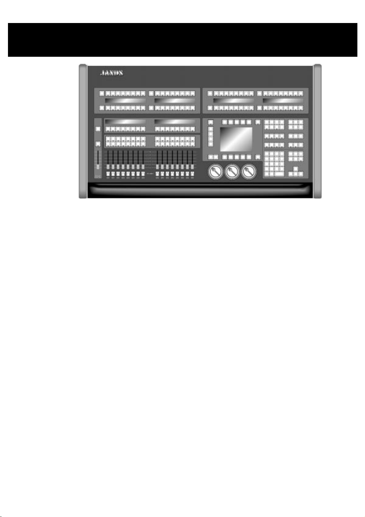
The HOG 1000 and 500 have emerged through a collaborative effort between Jands Electronics and Flying
Pig Systems, resulting in a family of co nsoles that combine the strengths of both companies: flexibility,
power and ease of use, without overwhelming your budget.
The HOG consoles offer a range of powerful features. These consoles feature the unique operating syntax
of the WHOLEHOG II: logical, quick programming and playback, without confusing function names. Just
like the WHOLEHOG II and the Jandshog, the HOG 1000 and 500 handle any combination of fixtures,
moving or static, with moving lights as simple to program as conventional fixtures.
The configuration of the desk makes programming a snap, with preset groups and focuses at your fingertips
in a series of menu banks. Liquid Crystal Displays provide continuous feedback on programming and
playback status. The flexibility and functional range of the HOG 1000 and 500 make them ideal for
handling the entire spectrum of lighting design, from complex theatrical shows, to unstructured television
or touring events.
Operational Overview
For WHOLEHOG II Users
The HOG is a quick jump from the WHOLEHOG II, with almost all of the syntax and programming the
same as on the WHOLEHOG II. There are a few hardware design differences, but in a short time, the HOG
should feel natural. The HOG and the WHOLEHOG II are so similar, in fact, that shows programmed on
the WHOLEHOG II are fully transferable to the HOG, and vice versa.
For Theatre Console Users
The HOG 1000 and 500 have been designed to be similar to a traditional theatrical memory console. In
particular, cues are programmed in much the same way as on a theatre console. The keypad gives access to
dimmer levels, fade times, and cue numbers. The editing keys and programming operations are also similar.
The playback uses cuelists and multiple part cues, an d timing can be split into in and ou t times.
However, in some respects the HOG is different:
An individual fixture is viewed as a fixture and not as a collection of separate parameters.
•
Fixtures have meaningful parameter names and level settings; for instance “blue” instead of 53%.
•
Parameters automatically respond appropriately to programming: for instance, the console will
•
automatically snap change a colour wheel while crossfading a dimmer—there is no need to set up two
fade times.
Welcome to the HOG •••• 1
Page 8

There are three parameter Palettes for creating looks quickly.
•
Most parameters use Latest Takes Precedence (LTP), but Intensity channels can playback in both
•
Highest Takes Precedence (HTP) and LTP on different Masters at the same time.
Multiple cuelists can be executed simultaneously. This means that there can be more than one “Cue 1,”
•
for instance.
Two types of blocking cues. The first uses the
•
cuelist. The second uses the
The console always operates in what is often referred to as
•
For Television Users
The HOG’s versatility makes it ideal for television applications, where flexibility in unstructu red situations
is paramount. Up to sixteen independent cuelists can be run simultaneously on their own Masters (eight on
an HOG 500), each one with its own active cues and timings. For example, when working on sets, this
allows each set to have its own cue list. Cue lists can be quickly copied from memory onto a fader, or
sixteen/eight (HOG 1000/500) can be replaced—with crossfading—in one button press by changing the
page. This makes it easy to access and re-order programming to cope with running order changes.
Powerful programming functions allow programming changes to be executed quickly; fixtures can be
automatically updated in their cues and presets, and snapshots can be taken to combine the output of several
cue lists. Additionally, cues and cue lists can be imported from old shows and incorporated into the current
show.
For Touring Console Users
The HOG is a step up from the traditional touring console, but you’ll soon find that accessing fixtures on
the console is as quick as reaching for a fader or button. The differences are the same as those for theatrical
consoles, but also include the following:
There are no preset faders for direct access. Instead, use the keypad to select a fixture, and the Palettes
•
or parameter wheels to grab the position, beam or colour parameter you want.
You set fade times as you program cues. Each parameter in a cue can have its own fade time.
•
Everything
function and blocks all fixtures on the console.
function and only blocks fixtures found in that
State
mode on a theatre console.
Live
The Wait time comes before the cue, and the Delay time (can be different for different parameters)
•
comes before a parameter crossfades.
Masters control a full cuelist rather than an individual scene or simple chase.
•
Using this Handbook
Where to Start
There are a few different ways to approach this Handbook when learning to use the console. If you’re a
seasoned board operator—or just impatient—jump right to the
chapter) to create looks right away. You can then use the
There’s also a
questions/problems and an
For a thorough overview, begin with the
for programming. Continue with the following chapters which explain the basics of programming and
playback.
Terminology
The following terms are used on the HOG:
Cue
Tells one or more fixtures to change settings for intensity, beam, colour, and/or focus using
Cuelist
Page
A group of cuelists residing on the faders. Pages can be changed, allowing the sixteen
Parameter
Frequently Asked Questions
Extended Key Chart
their delay and fade times. Theatre designers will recognise this term, Jands ESP2 users
know this as a “scene,” Event users will know this as a “memory”, while others may refer to
this as a “look.”
Cues grouped in a specific order to run one after another, or even simultaneously. These
may or may not be linked. Jands Event users refer to this as a “stack.” A chase is one type
of cuelist.
(HOG 1000)/eight (HOG 500) faders to be used for many cue lists.
An attribute of a fixture. A PAR can has one attribute: intensity. Moving lights also have
pan and tilt and usually several others such as colours and gobos.
chapter to assist you with responses to the most common
which summarises certain function buttons.
Getting Started
Index
chapter, which shows how to prepare the console
Quick Start
to quickly find the information you need.
section (after reading this
2 •••• HOG – Version 3.20
Page 9
ICBF
Palette
Timing
Path
Toolbar
ICBF stands for Intensity, Colour, Beam, Focus, and is an easy way to keep track of the
parameters for an fixture or a group of fixtures.
Intensity
Colour
Beam
also known as level, or percentage.
the colour wheel, the gel string, and colour mixing.
the pattern and quality of the light; this includes such specifics as gobo, gobo
rotation, sharp or soft edge, iris and diffusion. An
beam is full iris, no
open
pattern, no diffusion, and sharp edges.
Focus
also referred to as position. Indicates the
placement of the beam on stage
, as
opposed to sharp or soft optical focus.
A stored parameter setting—such as a colour—for one or more fixtures. Fixtures of
different types can share a palette. Changing a palette changes all the cues using that palette.
A palette is also known as a preset.
The timing elements used by the console are:
Fade Time
In Time
Out Time
The time, in seconds or minutes, for a cue to execute a crossfade.
The fade time for fixtures which are fading intensity up.
The fade time for fixtures which are fading intensity
down
.
In time = out time, unless otherwise specified.
Delay
Wait
The time that the console waits before starting a cue’s crossfade.
The time a cue will wait to executeafter the previous cue starts.
The type of crossfade used by a cue or fixture. Path is sometimes known as a dimmer curve
or a profile.
The 10 buttons (5) above and (5) below the main LCD. The function of these buttons
changes with the display, and their function at any time is displayed at the top or bottom of
the main LCD panel.
Symbols and Text conventions used in this Handbook
Different fonts are used in this handbook to indicate different actions:
This text
This text
for buttons to press on the console.
for buttons or text appearing on the LCD.
Particularly important information will be shown on a black background with a Stop sign in
the margin.
Useful HOG tips will be boxed with a pointing finger in the margin.
The Flying Pig is a shift key, used in conjunction with other buttons; we’ll refer to it as
the apple symbol on a Macintosh
®
; it must be held down while pressing another button.
. It’s used like
PIG
The @ key means “at” and is used for patching and setting levels on the keypad.
Welcome to the HOG •••• 3
Page 10

Safety Information
Please keep in mind the following safety instru ctio ns:
Do not use the console if the power cord is damaged or not properly connected to an
••••
Earthed socket.
Protect the system from extremes in temperature and wet weather. Operating temperature
••••
range for the console is 0 to 40o Celsius (32 to 104 F).
Keep drinks away from the console. More than one console has been destroyed by
••••
having a drink knocked into it.
Always handle the system with care and use a flight case when moving. Certain
••••
components are sensitive to shock and a drop could break them.
Only people with electrical expertise should open the back panel. There are exposed
••••
power items inside which can shock.
Repairs should only be undertaken by an authorised service representative. The warranty
••••
is void otherwise.
As long as these instructions are followed, and the system is treated with care, your console should last for
many years.
Problem Solving
If you’re having trouble with the console, there are several places to look for answers. If you have a
specific question regarding a function or a feature of the console, use the
find information on it. If you’re not sure where to look, or the console just seems to be acting strangely,
look through the
Crashes
As with any software product, crashes may happen on occasion, so while we do everything possible to
make sure that they happen rarely, we can’t guarantee that they won’t happen at all. Please help us
eliminate any problems by reporting them back to us.
There are two types of crashes: fatal errors and program faults.
When a fatal error occurs, the LCD will say
•
entire message and what you were doing at the time, such as: “1. Trying to edit a cue list. 2. The cue
list was on a template page.”
If you get a program fault, a stream of information will appear on the display screen. The top line will
•
start with
down all of the numbers on the
were doing just prior to the crash.
If you’ve had a crash, reset the console by turning off the power and turning it back on while holding down
the Enter key on the keypad. Press 1 to perform a
corrupted by the crash, you’ll need to load your most recent backup from disk. This is why it’s important to
back up to disk
Frequently Asked Questions
Fault at
frequently
and the second line will say
.
Trace
section for a problem which matches your own.
I’m sorry I’ve croaked
with several numbers following. Please write
Trace
line and send them to us along with a description of what you
Clean Start
Table of Contents
. Please write down the
. Because your show may have been
or the
Index
to
If you have time, try to reproduce the problem by repeating your actions. If you can send us a description
of how to repeat the problem reliably, then we are much more likely to be able to solve it rapidly.
Bugs
A bug makes the console behave strangely but does not crash. For example, you might find that a function
button does not work properly in certain circumstances, but works fine otherwise. This is a bug. If you
find bugs in the software, please let us know; the only way we can fix them is if our users tell us about
them.
Reporting Crashes and Bugs
The more information you can give us about the problem, the faster we can sort it out. Please use the
following format to report bugs:
4 •••• HOG – Version 3.20
Page 11

Reported By:
Your reference:
Model:
Software version:
Date:
Is the Bug repeatable:
Description:
Your name.
If you report more than one, please number them.
HOG 1000 or 500
You can find the number in the Control Panel title bar, or on the start up
screen.
Can you reliably reproduce the problem?
The steps from reset needed to reliably reproduce the problem, or failing that,
what you were doing to make the problem happen.
Please fax the bugs reports to +44 181 579 8469 or preferably e-mail them to
support@flyingpig.com
.
Software Updates
Over time the HOG software will be updated with new features and enhancements. The software will be
available from your dealer or over the Internet. In addition, revised fixture libraries will be released as we
generate personalities for new fixtures. To ensure that you can take advantage of updates, please complete
and return to Jands Electronics the registration card that was shipped with your HOG. If you include your
e-mail address, we’ll notify you when new versions are released.
The URL for Jands is
software by choosing the HOG page, and selecting Download New Software.
http://www.jands.com.au
. Once you’ve reached the Jands home page, download new
Getting Additional Help
If you have questions or need help, contact your local dealer. They’re trained to give you the support you
need.
If for some reason you aren’t getting the answers you need, or if you have comments or suggestions related
to the HOG, call Jands at +61 2 9582 0909. Someone is always available to field questions from 9:00 AM
to 5:00PM (local time) Monday through Friday. Problems can also be e-mailed to Jands at
jandsinfo@jands.com.au
You can also e-mail Flying Pig directly at
.
support@flyingpig.com
.
Welcome to the HOG •••• 5
Page 12

This Page intentionally Left Blank
6 •••• HOG – Version 3.20
Page 13
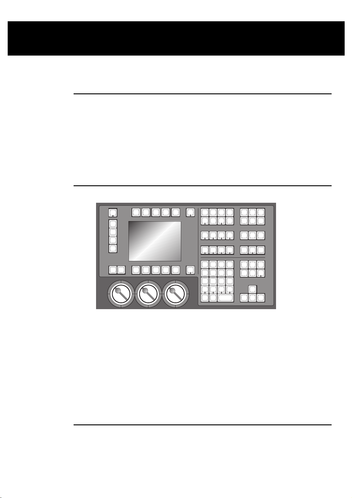
Finding Your Way Around
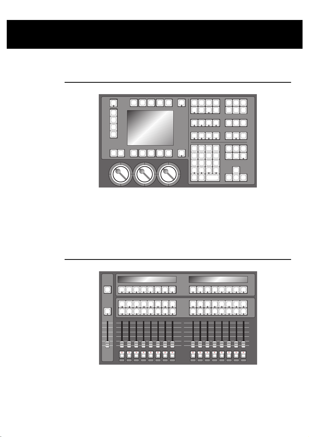
This chapter gives an overview of the console’s three main sections—the programmer, the playback
masters, and the displays—and the external items which connect to the console.
Programmer
The programmer section of the HOG selects fixtures and parameters to create looks on stage. The
programmer contains a numeric keypad and a standard set of buttons including
Thru, Full, @
, etc, which
are useful for programming fixtures and cues. Grouped nearby are the most frequently used programming
functions, such as
Copy, Delete, Undo
on other consoles—
Group, Position, Colour
, etc. In addition, the programmer contains four buttons not found
, and
. These buttons allow presets to be chosen
Beam
quickly from the keypad and are an easy way to create a cue.
Below the display screen are three Parameter Wheels, which offer another choice when programming. All
parameters can alternatively be set using the wheels to roll through until you find a colour, position, etc,
that you like.
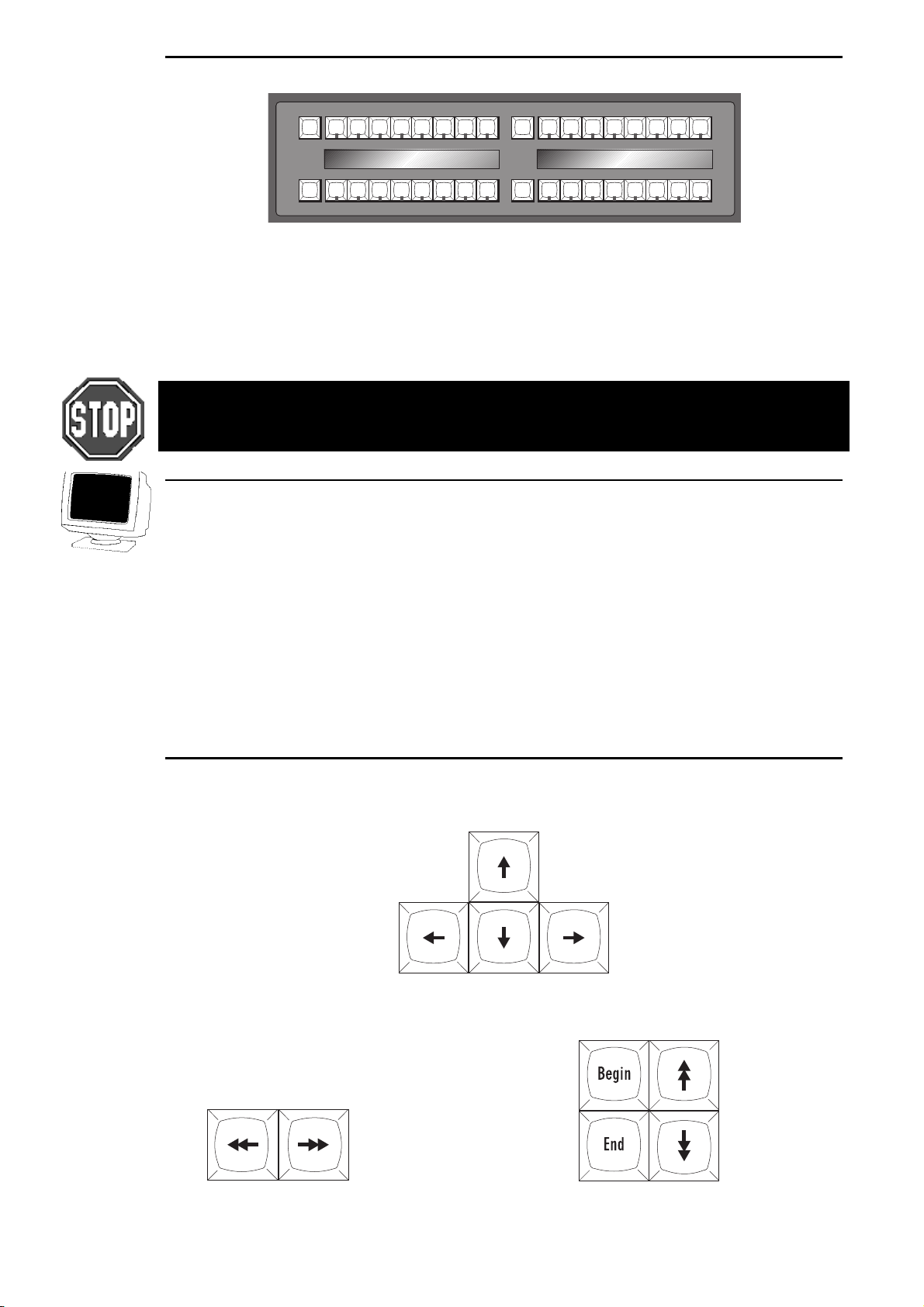
Playback Masters
10
8
6
4
2
0
FLASH
GRAND
GRAND
MASTER
MASTER
12345678 910111213141516
12345678 910111213141516
FLASH
There are sixteen playback masters on the HOG 1000 and eight playback masters on an HOG 500, each of
which can independently play back its own cue list. All masters can run simultaneously with various
custom settings. Actions such as add/swap, and button response can be individually set on each fader.
The Playback Masters can be recycled through the use of Pages, with each new page bringing up a clean
group of sixteen or eight faders to accept new cues and cue lists.
Finding Your Way Around •••• 7
Page 14
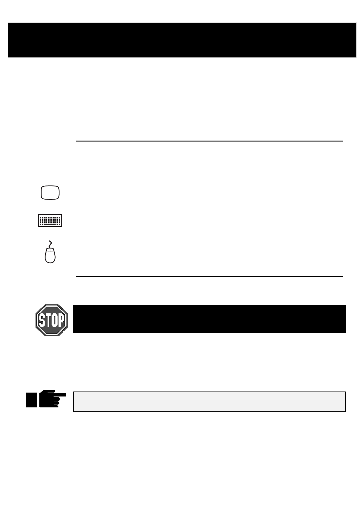
Menu Banks
The HOG has four Menu Banks for access to all presets and palettes, providing fast and efficient
programming. Each Menu Bank has sixteen preset buttons that can be programmed with specific Groups,
Colours, Positions and Beams. Button s that have been assigned palettes will indicate this with a red LED.
Those buttons with the LED off are empty. To the left of each bank is a page selection window with + and
buttons to cycle through all 10 pages; a clean set of sixteen more presets is available with each new page.
To access each preset, simply press its button. A list of the presets can be called up for naming by pressing
and
PIG
THE HOG 500 DOES NOT HAVE MENU BANKS. TO ACCESS THE MENUS, YOU MUST USE
EITHER THE EXTERNAL MONITOR OR A COMBINATION OF GROUP / POSITION / COLOUR
/ BEAM / EFFECT AND NUMBER KEYS.
Position, Colour, Beam
or
Group
as appropriate.
-
Displays
The HOG has a central Liquid Crystal Display, located to the left of the keypad, which displays
programming activity, menus for functions not found directly on the console, and windows to view cue lists
or palette lists
Near the bottom of the main LCD is the Command Line. This will tell you what fixtures are currently
selected for programming, and what palettes have been assigned to them thus far. To
up on the Command Line, simply backspace over it with the backspace arrow on the keypad.
Along the top and bottom of the main LCD are Toolbars; functions relevant to the current application will
appear here, and are accessed by pressing the buttons directly above or below them.
There is also the option for one external display (a standard PC VGA monitor may be used) which connects
to a port at the rear of the console and shows more information.
deselect
an item that’s
Navigation
Navigation through the console’s displays is achieved primarily through use of the Cursor Keys, located
beside the Keypad.
To move through a display window without altering the selection at the same time, use the Paging Arrow
keys above the cursor keys. They will move the display one screen at a time, like Page Up and Page Down
on a PC. The
Begin
and
buttons will select the first and last parameter respectively.
End
Page Left and Right Buttons Page Up and Down, Begin and End Page buttons
8 •••• HOG – Version 3.20
Page 15
Getting Started
This chapter covers everything you need to know to get the console ready for programming. In general, it
only takes four steps:
Connect together the accessories, cables and console.
1
Select the fixture types to use.
2
Patch them.
3
Program them.
4
Connecting the Cables
First, connect any external devices such as a keyboard, serial mouse/trackball or monitor to the
appropriately marked connectors on the back panel. A DMX lead should be plugged into the DMX port.
Connect the DMX data lead into the port marked
1
the rear of the desk.
If using an external monitor, connect it to th e port marked with
2
the VDU icon on the rear of the desk.
If using an external keyboard, connect it into port marked with
3
the keyboard icon. After powering up the console, it must be set
up for use with a keyboard by pressing the
Panel
keyboard
If using a mouse or trackball, connect it to the port marked with
4
the mouse icon.
on the toolbar, and finally highlighting
.
Setup
DMX-512
button, then
External
on
Power on
Plug in the power lead, making sure the lead is properly earthed and shares the same earth as the fixtures.
As with any DMX system, the console and the fixtures must share the same ground (ie, be
run off the same power), otherwise signal corruption can occur. If this is not possible, then
the console should be used with an optically isolated DMX buffer box.
Now turn the power switch on. If there’s a show resid ent in memory, the console will be read y for use. The
start up screen will say
clear the memory and start with a fresh console, or press
Old Loaded
. Press
to use the resident show in memory,
Okay
Load Show
to load another show from disk.
New Show
to
If there is no show in memory, the start up screen will say
and
Show
to load a show from disk, or press
Always keep a spare disk with your console to insert into the disk drive when moving the
console. This will help preventdamage to the disk drive.
Setting Contrast and Brightness
If the LCD’s don’t appear as easy to read as they should be, try adjusting the contrast:
New Show
Hold down the
1
Rotate the right parameter wheel to adjust the menu and playback
2
contrast, and the centre wheel to adjust the main display contrast.
button on the toolbar. Insert a show disk in the floppy drive and press
New Show
Setup
key.
to start with a fresh console.
Clean Start
, and there will be a
Load Show
Programming •••• 9
Load
Page 16
Fixture Selection and Patching
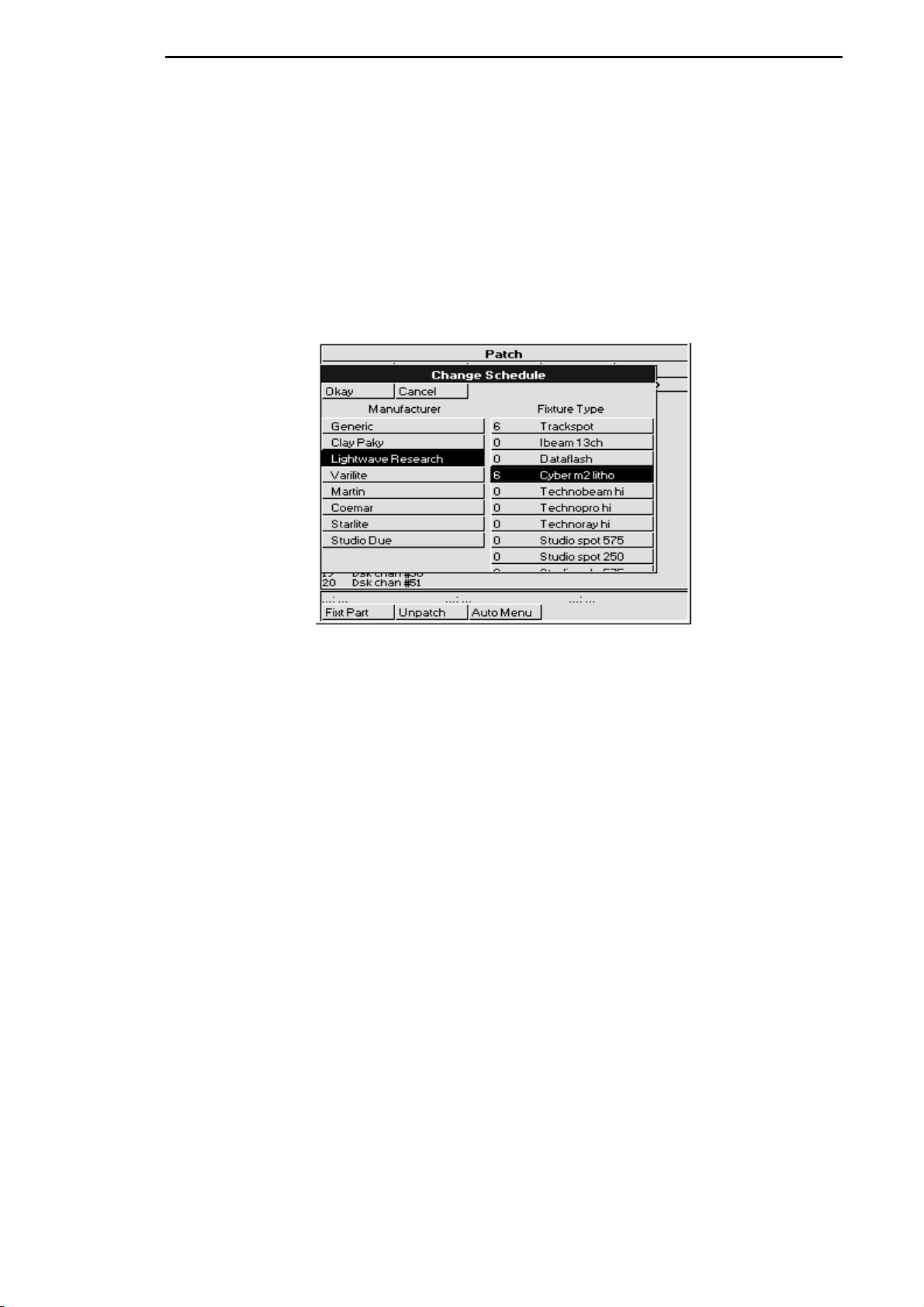
To select and patch the fixtures for a show, press the
Adding Fixtures to the Schedule
Once you’ve opened the Patch window, first tell the console how many fixtures of each type you’ll be
using:
1
Press
2
3
Add Fix
available. This opens the Change Schedule window.
Select a Manufacturer using the cursor keys to move
around the window and the right arrow key to make the
actual selection.
Select a fixture type using the cursor keys.
to see a list of the fixture types
button and then
Setup
on the top toolbar.
Patch
4
Press
Use the keypad to type in the new quantity in the ed it bo x
which appears over the current quantity of that fixture.
5
Press
6
Repeat steps 2 to 5 for each fixture type to be used.
7
Press
The fixtures listed in the schedule are all contained in the ROM
most major multi-parameter fixtures. If you aren’t able to find the fixture type, you can load it from an
older show disk, otherwise you will need to either contact your dealer to receive a fixture personality, or see
Chapter: Fixture Library
The examples in this Handbook use the following fixture schedule. You may want to set up your own
console this way and follow along.
24 Desk Channels for conventional fixtures (Dsk chan)
6 Trackspots® (Trakspot)
6 Mac500® m2 (Mac500)
6 Vari*Lite® VL5™ (Vl5 m3)
6 Vari*Lite® VL6™ (Vl6 m3)
6 Cyberlight® (Cyber m2 litho)
1 Miniscan hpe® (Minihpe)
Patching Fixtures
Now that you’ve chosen the fixtures to use, you can patch them.
to change the number of fixtures to be used.
Set
ENTER
Okay
.
to return to the Patch window.
to set it up yourself.
Fixture Library
, which has personalities for
In general patching fixtures is a three stage process, for example:
10 •••• HOG – Version 3.20
Page 17

1
Change to the correct type of fixture by pressing Group,
selecting the appropriate fixture type (eg Dsk Chan)
from the toolbar.
2
Type
3
4
While the Patch window is open the @ key means “patch at address,” rather than the normal “set at
intensity.”
Patching multiple times
Fixtures can also be patched to multip le locations. For example, selecting Track spots and typing
ENTER
location. Or,
Patching to a different output (HOG 1000 Only)
Any fixture can be patched anywhere on either of the two outputs. Every time you use the @ key, it will
patch onto the
select the other output, press the
Please note that whilst you can patch to both DMX outputs on an HOG 500, only output 1
connects to the DMX port on the back of the console. The ability to patch fixtures to both
outputs allows shows to be used on both an HOG 500 and an HOG 1000.
will patch Trackspot 1 to DMX channel 200 of the current output, in addition to its first patch
1 Thru 24
@ 1 ENTER
Type
consecutively from channels 1 through 24 on DMX
output 1.
Repeat for each fixture type.
2 @ 290 @ 300 @ 320 ENTER
current output
to select the 24 desk channels.
to patch the 24 desk channels
will patch Trackspot 2 to addresses 290, 300 and 320.
, indicated by the highlighted
Output>
button on the toolbar and continue patching.
1 DMX Output
or
2 DMX Output
1 @ 200
. To
Patching Split Fixtures like VL5s
Let’s proceed by patching the VL5s onto Output 1 at DMX address 40 for the intensity and address 320 for
the remaining parameters.
VL5s differ from most other fixtures in that they must be patched twice: once for intensity and once for the
other parameters. Press
display either
number is entered.
To patch the VL5s:
Press
1
and
Type
2
VL5 intensities to channels 40 through 45.
Press
3
Type
4
the parameters.
Different Patch Views
The patch window now shows where the VL5s are patched. To see the patch in more detail, press the
button on the patch tool bar. This displays a choice of views allowing some or all of the parameters, not just
the first one for each fixture. Move up and down the patch list by using the up and down arrow buttons and
press
ENTER
to select.
Fixt Part...
Patch
VL5 m3 Intensity...:
Group
ENTER
1 Thru 6 @ 40 ENTER
Fixt Part
1 Thru 6 @ 320 ENTER
, and then select
to select the other parameters for patching.
to toggle between the two. The command line on the display will
or
Patch VL5 m3 Pan...:
VL5 m3
using the toolbar
on the keypad. This patches the
on the keypad to patch the rest of
when the fixture
View
It’s also possible to view the patch display on the external monitor. Hold the
Patch
Monitor
LCD window) and use the Page Up and Page down keys to scroll the screen.
Now patch the rest of the fixtures:
Patch the Trackspots @49.
Patch the Cyber m2 lithos @ 190.
Patch the Mac 500s @ 100.
Patch the VL6 m3s @ 400.
on the toolbar. Move up and down the external display by selecting the external monitor (press the
button to illuminate the LED within, pressing it a second time will bring control back to the main
Monitor
button and press
Programming •••• 11
Page 18
Patch the Miniscan hpe @ 30.
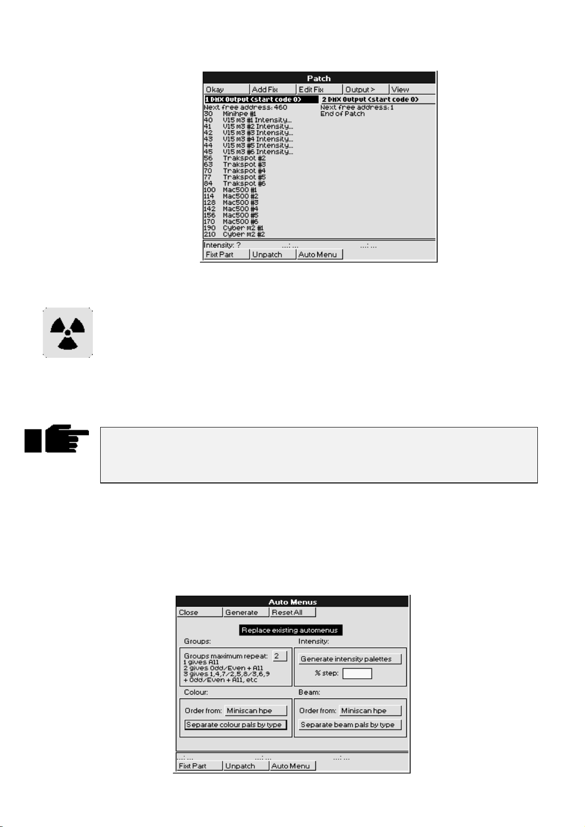
When you’re done, the patch list window will look similar to the one shown.
Clearing Fixtures from the Patch
To eliminate fixtures from the patch:
Select the fixtures - just as if you were going to patch them, but
1
do not press the
ENTER
button.
Select the output you want to clear them from.
2
Press
3
To clear an entire output, select the desired output to clear, press
(ie, after you’ve pressed the programmer
Press
Note: Parameters from unpatched fixtures will not be executed by masters. Thus a cue with
entirely unpatched fixtures will have no affect on the state of a master’s LEDs (ie they will
not turn on). In addition, unpatched parameters will be shown on the Output window as
Unpatched
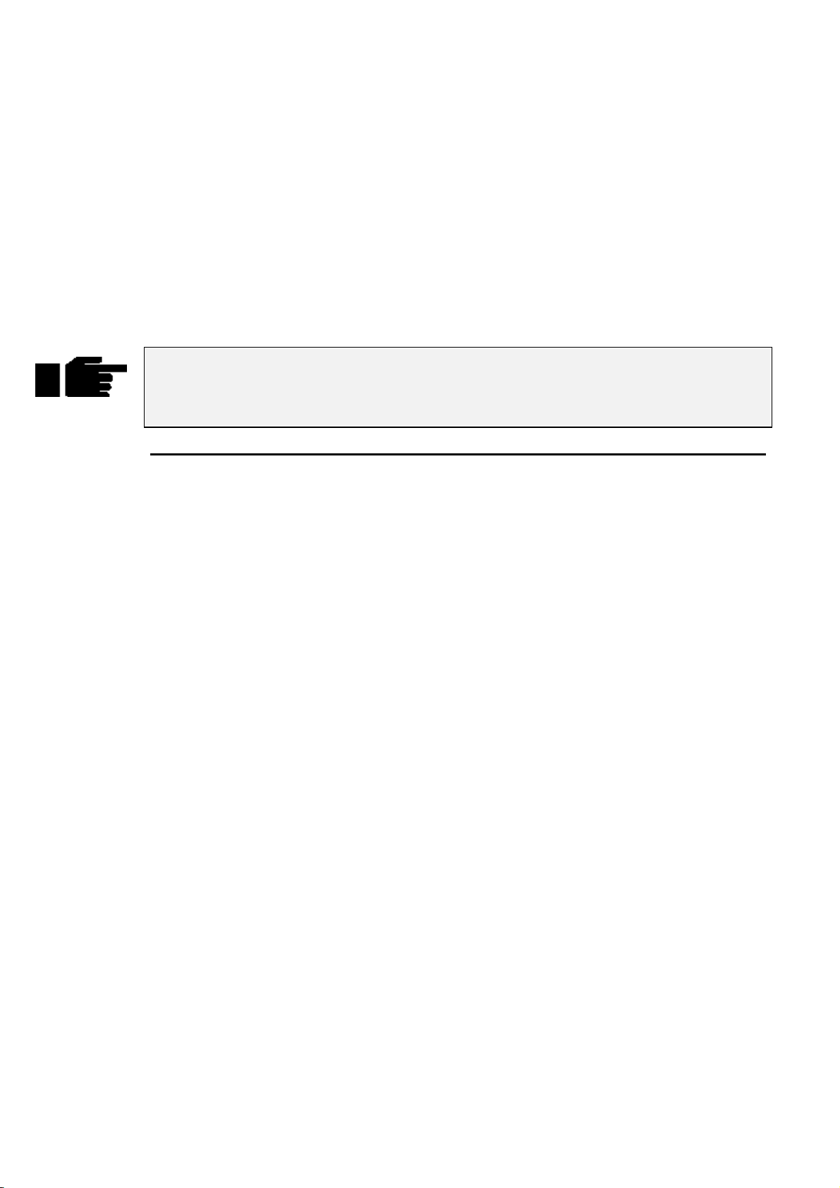
Auto Menus
It’s a good idea to use the Auto Menu function to set up standard palettes for the fixtures to be used. While
these palettes may not cover all your needs, they’ll give you a good base to start with. It’s best to only set
up the Auto Menus once, after you have patched all the fixtures that you are likely to use. While in the
patch screen press the
To generate auto menus, press
window, press
Okay
to finish.
.
Unpatch
chosen fixtures from the selected output.
Auto Menu
Reset All
on the bottom toolbar. This will remove the
Unpatch
button). The console will ask for verification.
Generate
.
clear restore
toolbar to bring up the Auto Menus window.
on the toolbar. If you wish to reset the options in the auto menus
while no fixtures are selected
12 •••• HOG – Version 3.20
Page 19
Options:
Replace existing automenus: Removes all previous groups and palettes generated by auto
menus, whether or not they would be overwritten. Note that if you
have manually edited a group or palette in any way, it will not be
deleted.
Groups max repeat value: Specify the maximum repeat value for groups, eg, 2 generates all,
even and odd, 3 generates all, even, odd, 1-4-7, 2-5-8, etc.
Generate intensity palettes: Specify whether you wish intensity palettes to be generated, and if
so in what increment (eg, 10%, 20%, etc)
Separate Colour/Beam palettes by type: Specify whether you wish to group all common range labels
together in a single palette for all types (eg, “red”), or keep them
separate (eg, “Cybm2 red”, “Vl5m3 red”, etc). If you select the
former option you can also specify which type to take the palette
order from.
Display:
The format of the palettes and can be changed to suit the console operator’s taste. Whenever a fixture
type’s name appears in an automenu, it has been abbreviated to be more easily legible when viewing menu
banks.
For groups: The first group in each set stores the sum of all type groups. For
example, the ‘ALL’ group stores every fixture type, ‘ODD’ stores
every fixture with an odd user number of each type, etc. They are
thus ‘global’ group palettes.
For beam and colour palettes: If the option to separate palettes by type is ch osen, the first palette
of each set is an empty marker palette labelled with the name of
the type in question.
Note that automenus incorporate any changes made to the fixture spreadsheet in the Edit
Fixtures window, so that if range labels are swapped or changed, the palettes will reference
the new ranges (automenus must however be regenerated to take account of any
subsequent modifications).
Fixture Alignment
Occasionally it’s necessary to hang a moving light upside down or sideways. To have all of the fixtures
moving in the same direction regardless of how they’re hung, use the fixture alignment features in the
Fixture Editing Spreadsheet.
To change an alignment:
1
Open the Fixture Editing Spreadsheet. This is found in
the Patch Window. To open the Fixture Editing
Spreadsheet from the Main display, press
Patch, Edit Fix
2
Use the
of fixture for which you wish to change the alignment.
3
Use the cursor keys to move around the Fixture Editing
Spreadsheet. Select a group of fixtures by holding down
the
select all the fixtures of that type, use the ALL row.
4
Press the
and Invert/Swap.
Group
key and using the up and down cursor keys. To
PIG
Set
.
button and the toolbar to select the type
key to toggle the selection between Normal
Setup
,
5
Press
Invert Pan
normal, and should be used for fixtures hung in reverse orientation to the others.
pan and tilt parameters for sideways-hung fixtures.
and
when you’re done.
Okay
Invert Tilt
make the pan and tilt parameters respond in a reverse manner to
Swap Axes
Programming •••• 13
swaps the
Page 20

Saving and Loading Shows
To avoid any potential loss of programming, save your show periodically while programming and at the
completion of every programming session. Shows should be saved on 3.5 inch 1.4 MB HD floppy disks,
formatted for IBM, just like those used with a PC. Disks can be fo rm atted in the
IMPORTANT: Always back up your shows to floppy disk. Do so frequently while
programming and always after completing a programming session. Also, we recommend
having several sets of backup disks and alternately saving to each one.
Note: Do not save to a disk that contains files you wish to keep, as the saving process
deletes the contents of the disk prior to saving the show.
Saving shows
To save to floppy disk:
Setup-Shows
window.
Press
1
Insert a disk into the drive. If it hasn’t been formatted
2
yet, the console will do so automatically.
Press
3
Press
4
When save process is finished , press
5
Loading Shows at Startup
When you start up the console, the last show in use will be in memory. If you’d like to work on a different
show, it must be loaded from floppy disk:
Insert the floppy disk with the show you wish to load.
1
Press
2
Press
3
new show.
When load process is finished, press
4
Loading Shows
If you wish to load another show without having to switch the console off and on again, use the Load
Shows window.
1
Insert the floppy disk with the show you wish to load.
2
Press
3
Press
4
Press
5
Press
new show.
on the desk.
setup
Save Show
.
Okay
Load Show
Okay
on the desk.
Setup
Shows
Load Show
to lose current show in memory and load
Okay
.
Okay
on the toolbar.
to lose current show in memory and load
Okay
.
.
.
twice.
New or Clean Shows
If you wish to start the console fresh with a new show, otherwise known as a clean show, this can be
achieved in two ways;
When powering up the console.
14 •••• HOG – Version 3.20
6
When load process is finished, press
Okay
twice.
Page 21

1
Press
2
3
New Show
The console will ask for confirmation if a show already
exists in memory. Press
The console is now ready to be programmed with a new
show.
Okay
to continue.
From the
You do not require a library disk to start a new show. The console now comes with a full
fixture library programmed into ROM.
Battery-Backed RAM
The RAM in the console is battery-backed, so that if you lose power accidentally, your programming will
normally be preserved. However, it is recommended that you always save your show to disk.
Change Show
1
Insert the floppy disk with the show you wish to load.
2
Press
3
Press
4
Press
5
Press
new show.
window.
on the desk.
Setup
.
Shows
New Show
Okay
.
to lose current show in memory and load
Programming •••• 15
Page 22

This Page intentionally Left Blank
16 •••• HOG – Version 3.20
Page 23

Quick Start
This chapter gives a quick overview of how the HOG operates. Here you’ll find what’s minimally required
to setup the console, program a cue, and play it back. This chapter is deliberately brief; for a complete
explanation of how the console works, start with the next chapter.
Setup the Console
Connect any external devices such as a keyboard, mouse/trackball
1
or monitor to the appropriately marked ports on the back panel. A
DMX lead should be plugged into the dmx port.
Plug in the power lead and turn the power switch on.
2
To use a saved show, insert the show disk and press
3
Load Show
new show, press
current show in memory once the startup screen appears.
Select and Patch the Fixtures to be Used
Open the Patch window by pressing the
1
Patch
once the startup screen appears. To create a
New Show
on the top toolbar.
. Press
Okay
to use the
button, then
setup
Press
2
3
4
5
6
7
8
9
Patching the Fixtures
1
2
Add Fix
Select a fixture manufacturer, such as “Lightwave Research”, by
using the lower RHS cursor keys to move around the window.
Press
Set
Again, use the cursor keys to select the fixture to use, such as
“Trackspot”.
Press
Set
keypad to type the new quantity (such as 6) into the edit box which
appears.
Press
ENTER
Repeat steps 3 – 7 for each fixture type to be used. To get
back to the Manufacturer window use the left or right
cursor keys.
Press
Okay
Press the
Select the fixture type you’d like to patch (eg,
pressing the corresponding button on the toolbar. Use the
More...
Group
to see the list of available fixture types.
to change to the Fixture Type window.
to enter the number of fixtures to be used. Use the
.
to return to the Patch window
button .
Trakspot
button if you can’t find the fixture you wish to patch.
) by
Select the fixture numbers you wish to patch. Use the
3
keys where required. Eg,
–
Press @ and enter the destination address you wish to patch the
4
fixtures to followed by the
ENTER
through 90 on DMX output 1.
Repeat for each fixture to be used.
5
Press
6
Establish Auto Menus
The Auto Menu function sets up standard palettes for the fixtures you’ve chosen.
patches the 6 Trackspots consecutively from channels 49
.
Okay
1 Thru 6
Enter
key. Eg,
Thru, +
1 Thru 6 @ 49
and
Quick Start •••• 17
Page 24
1
Press
Auto Menu
window.
on the patch toolbar to open the Auto Menus
Press
2
3
Palettes have now been created on the menu banks. If you are using an HOG 1000, the LCD displays at the
top of the console will display the contents of the Menu banks. To bring up the menu palettes on the
external monitor, hold down the
or
different palette buttons. If a palette button contains palette information that has no affect on currently
selected fixtures, the LCD will show four dots and the external monitor will display light grey palette
boxes. Empty palette buttons will be indicated by a single dash on the LCD and an empty box on the
monitor. Palettes that are currently being used are indicated on the mon itor by turning the palette button
white.
The red LED in the Monitor button lights up when the console is in External monitor mode.
ie, the cursor keys and other functions are operating on information in the External
Monitor. If the LED is not lit, then the console keys are operat ing on the inf ormation on the
main LCD panel.
buttons to bring up the display. Using either the mouse or the cursor keys, you can select the
Effect
Generate
them automatically.
Press
Okay
window.
on the toolbar and the console will generate
and then
Monitor
to return to the Patch
Close
button and press either the
Group, Position, Colour, Beam
Program a Cue
Open the Programmer Window
To open the Programmer window on the external monitor, press and hold the
press
Progrm
on the toolbar.
Monitor
button and then
Select Fixtures
Press a Group button from the Group menu bank or select individual fixtures by typing them in on the
keypad (for the purposes of this example, use a moving light).
Set Intensity
To get light output from the group you’ve selected, press
If you don’t want your fixtures at full, enter a different percentage on the keypad instead: press
ENTER
your selection.
Set Focus
Now, aim the fixtures.
Colour
to program 65% intensity. When choosing a level other than full, you must press
Type
1
2
3
4
1
1 ENTER
also press
displayed in the left hand column of the Programmer window.
Adjust focus position—pan and tilt—by moving the centre and
right parameter wheels.
To select the second fixture, press
Continue until all fixtures hav e been aimed.
Re-select the entire group of fixtures, so that the colour selection
applies to them all. Pressing
do this.
to select the first fixture in your group (you can
to select the first fixture). The fixture number is
Next
Next
Select
@ Full
.
then
. This brings them up to 100% intensity.
is a quick way to
All
ENTER
@ 65
after
Beam
Beam parameters are changed in the same manner as colour parameters.
18 •••• HOG – Version 3.20
Select a colour palette from the Colour Menu Bank. Alternatively,
2
press
Colour
and select a colour with the parameter wheel.
Page 25
Record the Cue
Once a look has been created in the programmer it’s easy to record it as a cue. To record cue 1 on the first
Playback Master:
1
2
Press
Record
Press the
.
Choose
button above Playback Master number 1.
Playback the Cue
Press
Clear restore
button stops playback. To clear a cue list on fader 1, first press fader 1’s
then press
Release
to empty the programmer. Press the GO button above Playback Master 1. The
Choose
.
button to select it and
Halt
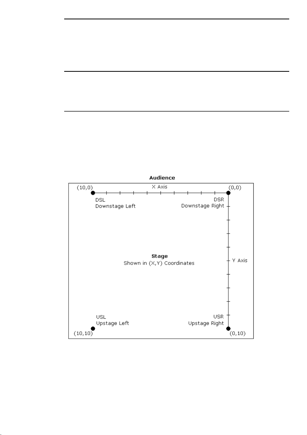
Setting up the Stage for XYZ Mode
Calibration
The XYZ system must first be calibrated before use. This process is simply a matter of aiming every fixture
at each of four calibration points. Accuracy is quite important, so you may want to iris down the fixtures
when aiming, if possible.
The map below shows the X and Y coordinates mapped onto a stage. Z is the height above the stage.
To calibrate fixtures:
Quick Start •••• 19
Page 26

6
Choose 4 points of a rectangle on stage which correspond
to the diagram above. The bigger the rectangle, the better.
7
Create four focus palettes – one for each point:
USR Upstage Right X=0 Y=10
USL Upstage Left X=10 Y=10
DSR Downstage Right X=0 Y=0
DSL Downstage Left X=10 Y=0
8
Aim all moving lights at each one of the four points and
record them into the respective palettes.
9
Select each of the four focus points in turn, press Set
twice and then choose the appropriate identifier (eg, Cal
USR).
10
Press
Select
11
Press
Calibrate
12
Press
Position
to X, Y, Z controls for programming in 3D space.
Note: XYZ information is recorded into palettes, but not into cues. When working in 3D
space, be sure to record all positions into palettes and then build your cues from the
palettes.
on the toolbar.
.
twice to change the parameter wheels
20 •••• HOG – Version 3.20
Page 27
Programming
This chapter covers the basics of programming. Once you’ve read it, you should be able to create and
record cues. This chapter assumes that you have patched the console as covered in the previous chapter.
Programming Styles
The HOG 1000 and HOG 500 have been designed to be inherently flexible, often providing several
different ways to achieve the same outcome. Which method is best for you will be determined by your
programming style. Ultimately, the conso le is a programming tool which lends itself to the user,s way of
working, and not the other way around.
More experienced users tend to devote a large portion of time to the initial console setup before even
beginning to program cues. Palettes are arranged to suit the user’s likes and dislikes, colours are mixed and
grouped, positions are setup, especially when using 3-D programming methods. We recommend that you
spend time learning to use the console and its options and then decide on the best way to program your
show.
Programmer Overview
The Programmer is where cues are created and manipulated. Here, fixtures are selected, levels are set, and
commands are executed. Programming is a three step process:
1
Select
2
Adjust
•
•
•
3
Record
It’s important to note that the programmer has priority over everything else on the board (with the
exception of the Grand Master and the Dead Black Out button). This makes it easy to see what’s happening
as cues are created, plus it makes it possible to quickly grab a fixture during a show and over-ride the
playback masters.
the fixtures or group(s) to program.
the parameter settings in one of 3 ways:
Wheels
Keypad
Palettes
the cue using
Record
or
Update
.
Selecting Fixtures
The first step in programming is always to select fixtures.
For example, to select all Desk Channels:
Quick Start •••• 21
Page 28
Find the Group palette button labelled
1
press it. This group was created when the
was used during set up.
All desk channels are now selected.
Alternatively:
ALL Deschann
Auto Menus
function
and
Type
1
Or you can select fixtures individually:
1
You’ll notice that after you selected the All Desk Channels group that some of the palette
button labels in the Focus, Colour and Beam windows changed to a light grey box. This
indicates that those palettes have no effect on your current selection
To program VL5s, select them using the
and toolbar buttons by specifying the
Group
fixtures were added to the patch in the Change Schedule window) followed by a slash and the fixture
number. For example,
Thru, +
Note: This will only work if you have 9 fixtures patched of the currently selected fixture. ie, if you have a
bank of Desk Channels in your patch list and also have VL5s currently selected and have 9 of them, start
with the programmer clear, and you will finish up with Desk Channels 1,2,4,5 and VL5 9 selected.
Selecting different types at the same time
You can select different fixture types simultaneously. For example:
and - with this as well. eg,
1
Group 2 ENTER
Type in the numbers you want, eg,
, or
3
Group 2 - 7
would select Desk Channel 5 (fixture type 1 / fixture number 5). You can use
1 / 5
Press
Group
, Select
on the keypad.
32 Thru 55
Group
1/1 Thru 5 -1/3 + 9
Dsk chan, 1, ENTER.
key and the toolbar. You can avoid having to use the
fixture type
.
, or
1 Thru 5 + 9 -
number (determined by the order in which the
Press
2
This selects Desk Channel 1 and Cyberlight 1 together. You can also press the
All Cybm2litho
we will see that you can record different types into one group and select them with just one button push.
Deselecting fixtures
Use the back arrow key to backspace over unwanted groups or fixtures.
Or you can deselect Groups by
Press
1
Press the group button to deselect
2
Finally, you can also press
programmer.
The Keypad functions
The keypad selects fixtures, groups, palettes, and times.
On the keypad, you’ll find the following keys in addition to the numbers:
Selects more than one item:
, Select
Group
group buttons. Once again the “/” button can be used to select different types. Later,
and hold it down.
PIG
Clear Restore
Cyberm2, 1, ENTER.
, but this will also erase any other information currently in the
Group 8 + Group 12
All Deschannel
.
and
22 •••• HOG – Version 3.20
Selects a series of items: Intellabeams
Backspaces through the previous item on the command line, which shows the most recent
selection you have made in the programmer. Selections become deleted as you backspace
through them. We call this key
6 Thru 15
Backspace
.
.
Page 29
Sets the intensity at 100%. It’s not necessary to press
automatically.
ENTER
after
Full
, it enters
Sets an intensity level or a patch location: VL5
Used for split fade times and sometimes fixture and cuelist selection:
Subtracts one item from a series: fixture
Completes an operation.
The four buttons above the keypad—
groups or palettes (like group number 19).
Group, Position, Colour
6 @ 40
1 Thru 10 - 5
, and
.
.
Beam
—are used to select specific
Adjusting Parameters
Setting Intensity
Select Desk Channels as above, then
Time 5 / 7
.
Move the left parameter wheel. The labels above the wheels indicate what the wheels control and their
•
current setting.
OR:
Press
•
OR:
Press
•
ENTER
Further selections can then be made and inten sities set fo r o th e r fix tu r es.
Intensities can also be set using the toolbar functio ns
and
+10%
0%, and
We will see how to change other parameter types later o n in th is chapter.
Blind
If you don’t want the programmer to output its contents, press
button is pressed again, when the programmer returns to normal.
Programmer Contents Display
The easiest way to keep track of what’s actually in the programmer is to use the
window. Open it by holding the
to set to 100%.
Full
@65 ENTER
sets the fixtures to 60%. For 6%, type
–10%
Rem Dim
. It is possible to skip the last digit for levels ending in zero. For example,
adjust the intensity up or down by 10%,
brings the intensity of all fixtures in the pr o g r am m er th at aren’t selected to 0%.
Monitor
and pressing
@ 06 ENTER
+10%, -10%, Out
Out
Progrm
.
brings the intensity of all selected fixtu res to
. The
Blind
on the toolbar.
, and
Rem Dim
LED illuminates until the
Blind
.
Programmer Contents
@ 6
Quick Start •••• 23
Page 30
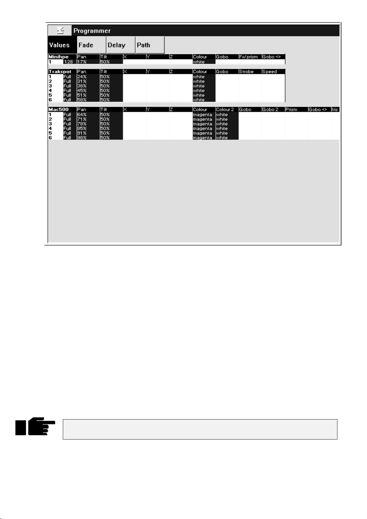
The Default setting is to show output values. To see fade times, delay times, or crossfade paths press
and either 2, 3, or 4 on the keypad. Alternatively, if you have a mouse or trackball connected, you can
point to the setting you wish to view and click on the left mouse/trackball button to select it. Pressing the
monitor
external screen.
The fixtures and parameters are shown in different colours to indicate their status:
Blue background
White background
Black text
Selecting the menu buttons at the top of the window shows more information:
Values
Fade
Delay
Path
Another useful display while programming is the Stage Output display. It shows the output of the entire
console, not just the programmer, and is accessed by holding
the toolbar.
button or clicking on the right mouse/trackball button will toggle between the console and the
Parameters currently selected in the programmer
Parameters of selected fixtures that have not been programmed
Parameters still active in the programmer, but part of a previously recorded
palette or cue.
Shows the values programmed for each parameter.
Shows the fade time programmed for each parameter.
Shows the delay time programmed for each parameter.
Shows the crossfade path programmed for each parameter.
Monitor
followed by the
Output
Pig
button on
Important: The Stage Output Window does not indicate the status of the Dead Black Out
button or the Grand Master.
Recording a Cue
Once a look has been created in the programmer you can record it as a cue. To record cue 1 on the first
Playback Master:
24 •••• HOG – Version 3.20
Page 31
Press
1
Record
.
Press the
2
Cue 1 has now been recorded on fader 1. The time for cue 1 will automatically be the default times
specified in the Control Panel. Don’t worry about setting your own times for now.
When cue 1 was recorded on the fader, a cue list for that cue was automatically created. To see this cuelist,
open the cue list window by pressing
indicated by a lit red LED on the
list actions. To see this display on the external mon itor, hold
Other ways of Recording
Pressing
•
Pressing
•
Pressing
•
Finally, typing
•
Cue Numbers
Every cue that’s created is given a number and assigned to a cuelist. Numbers can be up to 5 digits to the
left of the decimal and 4 digits to the right of the decimal, such as cue 12345.0001. These numbers refer to
cues in a specific cuelist,
completely different and not linked in any way. Nevertheless, it’s possible to copy or move cue 1 into any
other cuelist.
It’s important to remember that cuelists are not attached to a fader forever. Eig ht/sixteen new cuelists can
be loaded on the faders by changing page. Cuelists can also be copied and moved around just like cues. But
more on these items later.
Record
Record
Record 1.5
Choose
followed by
followed by
Record 3/1.5 ENTER
button above Master number 1.
and
Pig
Choose
ENTER
Choose
and
ENTER
not the entire console
inserts a cue numbered 1.5 into the cuelist on the selected master.
Choose
button. The selected fader becomes the default fader for all cue
appends the cue to the end of the cue list on the selected master.
appends the cue to the end of the cue list on the chosen master.
inserts cue 1.5 on fader 3.
. So there can be a cue 1 for cuelists 1, 2, and 3, which are
above fader 1. Note that this also selects fader 1, as
Monitor
and press
QList
.
Cue Names
Cues can also be given text names by pressing
Quick Name box and press
Choose
required name followed by
Cue Storage
Although the programmer retains all selections made since pressing
which have changed since the last record are recorded into cues. In most cases, this has no effect on
running the show; during playback the console automatically calculates what a cue should look like based
on what comes before it in the cuelist. Nevertheless, it’s possible to play back cues without this function
enabled. There’s also an option to record the entire
playback styles. More on these features in the
Clearing the Programmer
The programmer retains everything that’s lo aded into it until
you select some dimmers and record them into a cue then select some VL5s, the programmer will contain
both fixture types. Once
Clear
To restore the most recent contents back into the programmer, press
above the master containing the cue, cursor to the cue that is to be named, press
Restore
button turns off.
ENTER
ENTER
Clear
It’s a good habit to always press
. If you wish to name a cue that was previously created, press
.
Restore
is pressed, the programmer becomes empty and the LED in the
Clear
immediately after recording the cue. Enter a name in the
Set
and
Pig
and enter the
Set
Clear
—not just the changes—to allow for a variety of
state
Cues, Cuelists, and Pages
Restore
Clear
PIG
Restore
chapter.
plus
Clear
, only the parameters
is pressed. For example, if
Restore
.
Restore before starting to program new cues. This
ensures that lingering items from previous unrelated cues won’t be included in your new
cues.
A Brief Playback Overview
Let’s take a look at the cue we’ve made. To do so, you’ll need to clear the programmer since it has priority
over the rest of the console: press
contents.
Clear
Restore
. Or press
to stop outputting the programmer
Blind
Quick Start •••• 25
Page 32

First, bring up the fader on cue 1 to full. The fader acts as a submaster for intensity only. It has no impact
on colour, beam, or focus. Now press the Go button above Fader 1. The cue fades in with the programmed
time. If you didn’t see anything happen, make sure that the Grand Master is at full.
To freeze the fade at any point, press
Press
Release
the
Choose
To see the cues in a cuelist, press
If you used
to deactivate (ie, turn off, or remove from stage) the selected cue list, namely the one with
button LED lit.
PIG
while inspecting the cue, don’t forget to turn it off before continuing.
Blind
Pressing it again will fade back to the previou s cu e.
Halt.
and
Choose
.
Programming with Focus, Colour, and Beam
Let’s create a new cuelist that controls the Intensity, Focus, Colour and Beam of Cyberlights.
First press
in the new cue. Then press the
destination.
Start by selecting the
Position (Focus)
Typing
focus position—pan and tilt—can now be ad justed with the centre and right parameter wheels.
To select Cyberlight number 2, press
next Cyberlight. Continue this cycle until all of the Cyberlights ha ve been focused.
Colour
Re-select all the Cyberlights by pressing
press
controlling colour. If at any point you want to go back to adjusting focus parameters, simply press
Position
1 ENTER
Select
to return the focus parameters to the wheels.
Restore
Clear
selects the first Cyberlight (you can also select the first fixture by pressing
on the toolbar, followed by
to empty the programmer to make sure that the desk channels don’t get included
Choose
All Cybm2 litho
button above fader number 2 to select it as our programming
group and set them
. Adjust its focus settings and then pr ess
Next
All Cybm2 litho
). Press
All
Colour
.
Full
again to select the
Next
in the group palette (alternatively, you can
to make the parameter wheels swap to
Next
). Its
The parameter wheels are now ready to mix a colour for all the Cyberlights. By using the three parameter
wheels red can be generated. It’s also po ssible to access the red Colour Wheel setting s with the parameter
wheels. Since there are more than three colour parameters on the Cyberlight, you will have to press
again to scroll the wheels to show the Colour Wheel parameter. To return to the colour mixing wheels,
press
Colour
Alternatively, select the
Alternatively, type
one more time.
Red
Colour 2 ENTER
palette from the colour menu p alette to put the colour wheel in its red setting .
(this may differ depending on how the Colour palette is arranged).
Colour
To deselect palettes, hold PIG and then press the palette button.
As you can see, there are several ways to set parameter levels:
Wheels
•
Keypad
•
Palettes
•
Beam
Beam parameters include such things as iris, gobos, gobo-rotators, and edges. To access them on the
wheels, press
press
which beam functions you wish to modify on the parameter wheels by pressing the respective toolbar
button.
Beam parameters are adjusted the same way colour parameters are, ie, using either the wheels, palettes or
keypad. After selecting some beam settings the VDU will look similar to the picture on the following page.
several times to scroll through all of them. Alternatively, after pressing
Beam
. Fixtures such as Cyberlights have a number of beam parameters, so it’s necessary to
Beam
Beam
, you can select
26 •••• HOG – Version 3.20
Page 33

The white background in the output window shows what’s active in the programmer. If you can’t see a
certain fixture, press
example, press
Pig
plus a keypad number to bring the chosen fixture type to the top. In the above
Pig
plus 6 to bring the VL5 information to th e to p of the screen.
Once you’re happy with the cue, record it: press
You may notice that with some fixture types, like Cyberlights, there’s more than one wheel for Gobo, and
that one of these is followed by th is symbol: <>. This indicates a gobo rotator. The > and < signs on the
parameter settings point in the direction that the gobo will rotate.
Similar symbols appear when programming colour and gobo wheels for certain fixtures; these
symbols, >> and <<, refer to colour wheels, and point in the direction of the wheel’s rotation.
This symbol + indicates split colours.
Type and Wheel Selection
Apart from selecting palette numbers, the
functions. The
the available types. If there are more than four fixture types, the last button on the top toolbar will be
More…
button will advance through the toolbar menu.
Similarly, after selecting some fixtures, the
available parameters. Each toolbar button displays up to three parameter names, which are the parameters
that will appear above the three wheels when you select that button. For example, after pressing Beam:
. Pressing this will change toolbar pages to the next four fixtures. Repeated presses of th e
button is also used to select fixture types. Pressing it opens up a toolbar menu of all
Group
Record
Group, Position, Colour
Position, Colour
and then
, and
ENTER
Beam
.
and
buttons open up a menu of the
buttons have other
Beam
Group
Quick Start •••• 27
Page 34

The currently selected parameters are highlighted (Gobo, Gobo2, Fx/prism). Pressing a toolbar button takes
you straight to those parameters. Alternatively, repeated presses of the
buttons advance the selection through the menu.
Linked parameters
In contrast to focus and colour, only the altered beam parameters were recorded in the cue. While it usually
doesn’t make sense to record pan without tilt or magenta without cyan and yellow, beam parameters are
best recorded separately. Regardless, these default setting can be over-ridden if necessary in the Control
Panel, allowing a pan chase to be progr ammed independently of a tilt chase.
Now try saving your show to disk:
Position, Colour
or
Beam
Press the
1
Insert a 3.5” 1.44MB floppy disk into the drive at the front of the
2
console.
Press
3
4
5
Remember to SAVE OFTEN.
Press
Press
Save Show
Okay
Okay
key.
Setup
.
to confirm that you’d like to save.
to exit save window.
Recording Cues with Time
In most cases using the default fade time isn’t satisfactory and it’s necessary to enter different times. This is
easily accomplished during the programming process by pressing
Select fixtures and set levels.
1
Press
2
3
Time 2.04 ENTER
Press
Record
the selected Master.
and
to select a fade time of 2.04 seconds.
Choose
button to record the cue on
Time
:
When
one for the Cyberlight:
28 •••• HOG – Version 3.20
is pressed, a window opens showing all the parameters for the programmed fixtures, like this
Time
Page 35

The
Beam
specific parameters (time values can have up to 2 decimal places of precision eg, 5.11 seconds).
line in this window sets times for all parameters. Use the
All
lines to set times for all parameters of those types. Below these lines, times can be entered for
Intensity, Focus, Colour
, and
To set different delay times, use the cursor keys and
Once you’re done adjusting the times, press
permanently open, press
Different times for different fixtures
If different fixtures need different timings, repeat selecting fixtures / setting times, for as many different
times as you need. For example, to create a peel off where fixtures move from a point, one by one:
Create the starting position and record it as a cue.
1
Select fixture 1, press
2
select the Delay column. Type
delay time of 1 second.
Press
3
4
5
Note: if you want to leave the timing window open, you can do so by holding
this case, you need to press
Checking your cue before you Record
You don’t have to record a cue to check to see how the timing will work out.
1
Next
and do the same as in step 2 but with the new delay time.
Continue for all fixtures.
Record this as the second cue.
Press
Try Cue
an alternative to the snap change of
and
Pig
Time
to select the next fixture then press
to insert new times
Set
to fade out the programmer (note: this is
ENTER
, but you will need to press
and use the cursor keys to
Time
1 ENTER
to change to the Delay column.
Set
to close the Time window. To keep the Time window
before editing times.
Set
to give it a
Time
and pressing
Blind
PIG
).
Time
. In
Press
2
Changing timing after Recording
After recording, it’s possible to globally adjust a cue’s time in the cuelist window with the
However, to set different times on individual parameters—and not one time for the entire cue—it’s
necessary to first
Split timing
Split timing means that when the cue executes, fixtures whose intensities are going up (“In” fixtures) will
have different timing to those fixtures whose intensities are going d own (“ou t”). So a split time ha s both an
In time and an Out time.
Use / to enter a split fade time (one with both an in and out time). For example,
of 2 seconds and an out time of 4 seconds. / can also be used to enter a split delay time.
Specifying minutes
Hold the
Time values can have up to 2 decimal places of precision (eg, 5.11 seconds).
PIG
Try Cue
Load
key and press
again to fade the cue in with time.
button.
Set
the cue back into the programmer. More on these items in the chapters to come.
would have an in time
2/4
to get minutes.
.
Quick Start •••• 29
Page 36

Changing the default cue times
You can change the default times for fade and delay in the Control Panel window (
console will automatically use these for your cues unless you make a change while programming. See
Customising the Console
.
Setup Panel
). The
30 •••• HOG – Version 3.20
Page 37

Groups and Palettes
In addition to the palettes created by Automenus, you can create custom groups and palettes to meet your
own specific needs. These may be combined with one another or manipulated in any way.
Creating and Modifying Groups
You can make your own groups for quick fixture selection. A group can include any number of fixtures and
any combination of fixture types.
To create a fixture group:
Select the fixtures for the group, such as
1
Trakspot 1 Thru 3 ENTER.
Press
2
3
Naming a Group
To give the group a name:
Record.
Select the destination by pressing an empty space in the Group
menu bank (or type in a destination group number:
ENTER
).
Cyber m2 1 Thru 3 +
Group 13
Press
1
Type in a name, like Stage Right, on an external keyboard or by
2
using the keyboard built into the right menu banks.
Press
3
Changing an existing Group
To remove fixtures from a group or combine fixtures into a group:
Select the desired fixtures to add or remove
1
Press
2
Options toolbar.
Choose an option from the Options toolbar:
3
fixture into the destination or
destination.
Select the group to be changed.
4
Press
5
You can also use
Press
1
Either
2
Press
3
Set
ENTER
Record
ENTER
and
Load
Load
Knockout
Update
.
.
. The Programmer toolbar will be replaced by the
Merge
Remove
.
Update
, followed by the group you want to change.
.
to modify a group
existing fixtures, or select new ones.
to eliminate them from the
to combine
Finally, existing groups can be combined to make new ones.
Creating and Modifying Palettes
Palettes are a useful programming tool giving quick access to parameter levels. There are three types of
palettes: Position, Colour, and Beam. Position palettes are also referred to as preset focuses.
Why are palettes useful?
They’re a quick way to retrieve common positions or colour mixes.
•
Groups and Palettes •••• 31
Page 38

They automatically update. Any change in the original palette will be automatically reflected in all
•
cues that use it.
They can be named properly. These names appear across all display types.
•
Like groups, palettes can be made from any combination of fixture types. For example, a Red palette
•
could contain red for scrollers, VL5’s, Cyberlights, Super Scans, and Roboscan 1220’s, assuring that
colours match every time.
To create a palette:
Select fixtures and adjust the parameters to be included in the
1
palette.
Press
2
3
4
If you create a palette with one fixture, this setting will apply to all of the fixtures of that type. If a palette is
recorded with more than one fixture of th e same type, then each fixture of that type will receive its own
value.
If you try to create a palette over the top of an existing palette, a message box labelled
“
Choose edit
between
palette button you have chosen and push all palette buttons from this button onwards one
place to the right.
replace it with the information in the programmer.
contents into the destination palette. If there’s a conflict, the information in the
programmer has priority. Cancel will abort the process.
Naming Palettes
To name an existing palette, open the required palette window using
Beam
Insert, Replace, Merge
. Select the palette to name with the cursor keys, press
Record
Press the destination palette location (or type in a destination
palette number:
To name: press
the palette.
” will pop up telling you that this item already exists and ask you to select
.
Position 21 ENTER
, type in a name, and press
Set
Replace
will delete the current contents of the palette button and
).
and
Cancel. Insert
ENTER
Set
to name
will place the new palette in the
combines the programmer
Merge
+
PIG
Position, Colour, Group
and enter name followed by
ENTER
or
.
Masking
When palettes are recorded, the programmer au tomatically filters ou t parameters that are not approp riate to
that palette type. For example, if intensity is at full when creating a focus palette, the intensity will no t be
included.
However, it’s possible to over-ride this masking if you want to record intensity into a Position palette, for
instance. To over-ride masking:
Select fixtures and adjust the parameters to includ e in the palette.
1
Press
2
3
Press the destination palette location, eg, Position 2
4
ENTER
Record
replaced by the Edit Options toolbar.
Press the
toolbar. This means that Colour and Beam will not be
included, but that intensity an d Focus will be.
.
. You will see that the programmer toolbar is
Use I
and
Use F
option in the bottom
32 •••• HOG – Version 3.20
Page 39

Embedded Palettes
It’s possible to create a palette that is actually comprised of other palettes, making it easy to grab a palette
giving different fixtures custom settings. One particularly useful application for this feature is with position
palettes. Often stage looks are built up from many individual focus positions. Embedded palettes make
putting multiple fixtures in th eir own focus positions as simple as one button press.
As an example, let’s say we created a palette from the following arrangement:
Fixture 1 Drums
Fixture 2 Singer
Fixture 3 Bass
Fixture 4 Keyboard
Fixture 5 Guitar
Embedded palettes let us recycle existing focuses (Drums, Singer, etc)., so we don’t have to create this new
look from scratch. This not only saves work while programming, but reduces the number of focuses to be
updated.
Modifying Existing Palettes
There are two ways to modify a palette:
1) use
Record
2) use the
The first method works just like modifying groups:
Merge
in the programmer has priority. It’s possible to merge into multiple palettes simultaneously: select the
destination palettes numerically on the keypad or hold down
Remove
all
parameters are wiped out, while the other parameters remain in the palette. To remove fixtures from
multiple palettes simultaneously: select the d estination palettes numerically on the key pad or hold down
Record
In the second method, the item to modify is first selected:
combines the programmer conten ts into th e destinatio n palette. If there’s a con flict, the inform ation
parameters for a VL5 but only Intensity has been altered in the programmer, only the Intensity
with either the
and
Load
1
2
3
4
deletes selected fixtures and parameters from a palette. It is parameter specific: if the palette has
while pressing the palette buttons.
Update
Select the fixtures you want to change and set the new
parameters.
Press
Record.
Choose an option:
or
Remove
Select the destination palette.
Merge
buttons.
to eliminate them from the destination.
or
Merge
Remove
to combine them with the destinatio n
option or
Record
while pressing the palette buttons.
Groups and Palettes •••• 33
Page 40

Press
1
Select the palette to modify.
2
Select the fixtures and modify their parameter settings as though
3
you were initially setting them up in the programmer.
Load
.
Use
4
5
Modifying Palettes while running a Show
While running a show, you can over-ride fixtures using the programmer. If you want to store the new
settings permanently, you can use the auto update feature to identify what programming was over-ridden
and thus where to store the changes. For example:
1
2
3
4
5
This method is useful when playing back a cuelist during a show and a preset focus position needs
updating. You need only select the fixtures to modify and adjust their pan and tilt settings. Once
pressed, the update window shows the fixtures’ preset focus and lets you select them for immediate
updating.
Knockout
Press
Update
Hit Go on several Playback Masters with cuelists.
Grab some fixtures and modify their settings.
Hit
Update
window will pop up showing all the cues and palettes that have
been over-ridden. Note, the current cue of the
always be selected by default. If the window does not pop up,
then either you have not made any adjustments in the
programmer, or you already had something loaded.
Select the items you want to update by using the cursor keys and
Enter
key to highlight them.
Press
okay
or
.
. The command line will show
to update selection.
to remove unwanted programming.
Undo
Auto Update
selected
master will
. A
Update
is
As you’ll see in the next chapter, cues can also be modified this way.
Manipulating Groups and Palettes
Groups and palettes are flexible items which can be moved, copied, or deleted at will. Note: all of the
following edit functions also work for cues, cuelists and pages.
Copying and Moving
To copy or move a palette (or group) to a new location:
Press
1
Select the item to copy.
2
Select the new location for the item.
3
To copy or move multiple items, use this syntax:
Press
1
Select the items to copy (these must all be in the same menu bank,
2
ie, all Group buttons, or all Colour buttons, etc).
Release
3
Select the new location (the items copied (mo ved) will fill up the
4
menu buttons starting at the new lo cation and continue filling up
the locations to the right until all cop ied (moved) locations have
been placed).
Copy
Copy
Copy
(or
(or
Move
Move
(or
).
) and hold it down.
).
Move
If you select a destination that is already in use, the item being copied (moved) will be
given an item number with a decimal value and the existing items will move one (or more)
positions to the right on the menu buttons.
Alternatively, you can use the keypad. For example:
34 •••• HOG – Version 3.20
Copy Colour 5 thru 12 @ 20 ENTER
.
Page 41

Merging Groups or Palettes
Palettes (or Groups) can be combined with one another by selecting the
Merge
option
Press
1
programmer toolbar
Select the item to merge
2
Press
3
options that might be necessary.
Select item to merge into.
4
Again, it is possible to Merge multiple items at a time by ho lding
not possible to merge a Group into a Palette. Where there is conflict between what’s in the programmer and
what’s in the cue, the programmer takes pr iority.
Deleting Groups and Palettes
To delete a group or palette:
Press
1
Select the palette to be deleted.
2
Press
3
OR:
Press
1
select the palette to be deleted. If you select the wrong
2
palette button, pushing the palette button a second time
will deselect that button.
. The Options toolbar will have opened on top of th e
Copy
Merge
Delete
ENTER
Delete
from the Options toolbar, and apply any masking
.
.
and keep holding it down.
, or using the keypad syntax. It is
Copy
3
Release the
Delete
button.
Groups and Palettes •••• 35
Page 42

Cues, Cuelists, and Pages
This chapter covers cues, cuelists, and pages. You’ll learn how to edit, copy, and work with all three items.
Manipulating Cues
Viewing Cuelists
To see a list of the cues within a cuelist, hold down
cuelist. Alternatively, you can hold down
be displayed on the external monitor (to change between cuelists, press
If the desired cuelist is not on the current page, you will need to change pages first).
How to Select Cues During Edit Operations
Cues are selected in the same way as Groups or Palettes. After pressing the
button:
Load
Type in the cue number on the keypad. Unlike Groups or Palettes, there is no prior “Cue” button to push.
When you type in a number, the console assumes you are referring to cues in a cuelist on the selected
playback master (the one with the
For example, typing
Modifying Existing Cues
The technique is the same as for modifying palettes:
2/3 ENTER
Choose
would select cue 3 on playback master 2.
Monitor
LED lit). The / key can be used to select cues on other masters.
and press
and press
Pig
Choose
on the keypad for the current cuelist to
QList
Choose
button for desired fader’s
button for desired cuelist.
Record, Copy, Move
, or
1) use
Record
2) use
Load
3) using
The first method uses the
combines the programmer contents into the destination cue. If there’s a conflict, th e information in
Merge
the programmer has priority. It’s possible to merge into multiple cues simultaneously by entering the
destination cues on the keypad separated by +.
Remove
parameters for a VL5 but only Intensity is altered in the programmer, only the Intensity parameters are
wiped out, while the other parameters remain in the cue.
The second method uses
before updating back to the original cue.
along with
/
Update
Update
Select fixtures and adjust parameters.
1
Press
2
Press
3
Type the cue number and press
4
deletes selected fixtures and parameters from a cue. It is parameter specific: if the cue has
Press
1
Select the cue to modify via the keypad.
2
or
without
Record
Merge
Load
Load
Record
Load
.
or
Merge
.
or
Remove
(Auto Update).
button in a similar manner to the way cues are created in the first place:
Remove
to bring the cue into the programmer where it can be modified directly,
,
on the toolbar.
ENTER
.
all
The third method uses
This method is a convenient way of adjusting programming while in a live environment.
36 •••• HOG – Version 3.20
All fixtures in the cue are automatically selected and ready for
3
instant modification. To only modify some fixtures, just select
them normally and only they will be changed.
Press
4
Update
to record the changes.
Update
on its own.
Load
must
be pressed for this to work.
not
Page 43

Select fixtures and adjust parameters.
1
Hit
2
3
4
Copying, Moving, and Deleting Cues
Cues are copied, moved, and deleted with the same commands used elsewhere on the console.
To copy or move a cue:
Update
window will pop up showing all the cues and palettes that have
been over-ridden. Note, the current cue of the “selected” master
will always be selected by default. If the window does not pop up,
then either you have not made any adjustments in the
programmer, or you already had something Loaded.
Select the items you want updated using the cursor and
keys.
Press
. The command line will show Auto Update. A
to update.
Okay
ENTER
Make sure that the cue’s cuelist is selected.
1
Press
2
Enter the source cue number.
3
Press @ (@ means “to”).
4
Enter the destination Cue number. If the cue exists the cue will be
5
inserted just before the destination cue.
To select multiple items, press
multiple fixtures:
Cues can also be copied to other cuelists. For example:
cues 1 through 4 in Master number two’s cuelist to cues 12 through 15 in Master number five’s cuelist.
Just like manipulating Palettes, you can use
while copying cues.
Mask
To delete a cue:
1
2
3
Please note that the Delete command cannot be reversed. Unless you have the information
on a backup disk, it will be completely lost.
Copy 1 Thru 4 ENTER @ 12
Press
Enter the cue number to be deleted (Fader number / Cue number).
Press
or
Copy
Delete
ENTER
.
.
Move
Copy
.
and use the keypad to select a range of cues, just like selecting
.
Copy 2/1 Thru 4 ENTER to 5/12
in conjunction with the Options toolbar to
Copy
will copy
Merge
, or
Summary of Recording Options
State and Everything
Normally when recording a cue, only the parameters you adjusted since the last record are included in the
new cue. For example, if only the pan and tilt wheels are tou ched before recording, the cue wo n’t contain
information for intensity, colour, or any other non-focus parameter.
This system has two advantages. One is that cue storage is extremely efficient, since programmed values
are not repeated throughout a cuelist. The other is flexibility during playback. Some shows are programmed
with only one parameter type in each cue or sequence, allowing them to be combined with each other in
Cues, Cuelists, and Pages •••• 37
Page 44

different ways to achieve a wide selection of looks. This would not be possible if the console always stored
values for each parameter.
However, this system can occasionally be confusing, and sometimes recorded cues don’t appear the same
during playback as they did while in the programmer. This problem usually has one of two causes:
1)
Active cues on the playback masters while recording
programmer and the playback masters, but only what’s in the programmer is recorded in the cue. Later,
when the cue is played back, it will look different if the cues that were active while recording are now
turned off.
2)
Active cues during playback outputting values for parameters not included in the recorded cue
Cyberlight is programmed with only intensity, colour, and focus information, an iris setting will not be
included in the cue. If this cue is activated after another cue has put the same fixtures in a tight iris, the iris
will remain tight even though it was open when recorded. This is because no information was programmed
for iris since it was not touched.
. The look on stage is a combination of the
. If a
and
State
a cue.
Pressing
programmer since the last time
Pressing
taken. This ensures that the look on stage during playback is exactly the way it looked during
programming. Recording with
conventional console. In contrast, State only creates a blocking cue for the fixtures used in the specific
cuelist.
When copying cues, pressing
not just the cue. This corresponds to the sum of all the cues up to and including the selected cue. When
loading cues, pressing
Unblock
Whenever State or Everything are used, parameters will often repeat settings pro grammed in earlier cues.
These are known as hard commands. Hard commands are also created during the normal course of
programming. Sometimes these hard commands are deliberately included, but sometimes they are the by
product of cue manipulation. To eliminate unwanted hard commands, use Unblock:
Everything
State
Everything
1
2
3
on the toolbar after
Press
unblock.
Press
Enter a range of cues to unblock.
let you avoid these problems and control how much is included when recording
Record
Restore
Clear
records the entire output from the console, as though a “snapshot” were being
Everything
copies the entire state of the cuelist up to the point of the selected cue,
loads the cuelist state into the progr ammer.
Choose
on the cuelist toolbar.
State
and the
Pig
Unblock
State
will record everything that’s been entered into the
was pressed.
selected is the equivalent of creating a blocking cue on a
button for the cuelist to
Press
4
Eliminating unnecessary hard commands is a good way to reduce show size on disk.
Grabbing All Parameters
To force values into all parameters for the selected fixtures in the programmer, press
Thus, even if a parameter is not adjusted while programming a cue, it will contain its current level upon
recording. If the parameters are not controlled by any cues, then this will be the default settin gs from the
fixture library.
Track Fwd/“Cue Only”
Use this after
between the two options:
Track Fwd On
Track Fwd Off
In addition, when you press the
function, the change will stay for one ed it operation only. It will revert to th e default setting for the next
operation.
ENTER
Record, Copy
The cue will track its changes through the subsequent cues until there’s a change
previously programmed. This is the normal programming mode.
This is also known as
cue so it reverts to its previous state prior to the operation. In other words, the changes
are undone in the next cue.
.
or
Update
Track Fwd
by pushing
Cue Only
button to enable or disable the “
Track Fwd
. Using the
button on toolbar. This button toggles
Cue Only
and
Pig
option changes the following
Edits Track Forward
Active
.
”
38 •••• HOG – Version 3.20
Page 45
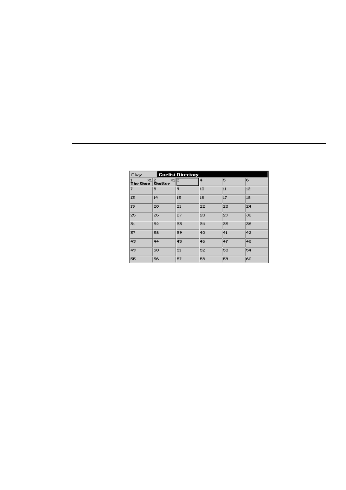
However, you can use the control panel window button “
default.
Merge and Remove
Use these options after
rather than insert new cues.
Masking/Use
As we’ve seen, it’s possible to filter out Intensity, Focus (Position), Colour, Beam, or Time settings by
pressing the relevant Use button(s) on the toolbar while recording (the default setting of the Use buttons is
neither selected or deselected, but rather allowing the console to choose what parameters should be
recorded). For example, if all parameters for a fixture are selected in the programmer and
after
Record
information will be ignored. Any combination of the Use buttons can be selected/deselected when
recording a cue, parameters that have not been modified in the programmer will be not be recorded even if
the Use button for that parameter has been pushed.
, colour information will be included in the cue and Intensity, Focus, Beam and Time
Record
and
Copy
Merge
(
only) to combine or remove fixtures from existing cues
Edits Track Forward
” to change the
is pressed
Use C
Cuelists
Every cuelist is stored in the cuelist directory window. Open the window by pressing
PIG
and
List
:
Any cuelist can be accessed at any time from this window.
Cuelists can be selected, copied, moved, and deleted, just like groups, palettes and cues. Merging cuelists is
more complicated:
Merging Cuelists
To merge two cuelists, they must both be on Playback Masters
Press
1
Select
2
Select the cues to merge from one cue list. Use
3
Press
4
Select the cuelist and all of the cues to merge into with the keypad
5
(eg,
selected.
Press
6
If the selected destination has more cues th an the source, the source cues will repeat themselves until the
end is reached. If the reverse is true, then merging will cease o n ce the end of the destination is reached.
Naming Cuelists
Cuelists cannot be named via the master itself. You must find the cuelist in the cuelist directory and name it
there.
.
Copy
on the toolbar.
Merge
@.
1/2 Thru 5
ENTER
.
and +.
thru
). To merge into more than one, all cues must be
Cues, Cuelists, and Pages •••• 39
Page 46
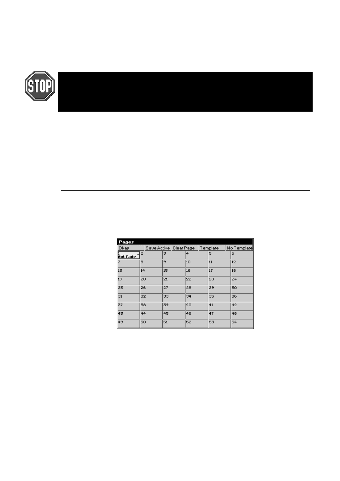
Open cuelist window using
1
Pig
and
List
.
Use cursor keys and hit
2
Type in cue name using keyboard built into the menu banks or
3
use an external keyboard.
Press
4
HOG 500 users: If you do not have an external keyboard connected to your console you
will not be able to enter cue names and other alphanumerical information.
HOG 1000 users: If the external keyboard is not present but selected in the Control Panel
window, you will not be able to change the name of the cuelist.
Deleting Cuelists
To delete a cuelist permanently on all pages, delete it in the cuelist directory window. To only delete it from
the Master, hold
To permanently delete a cuelist:
1
2
3
Delete
Press
Press
Press
ENTER
Delete
List
ENTER
.
while pressing the Master’s
.
and then enter cuelist number.
.
to select the desired cue to name.
Set
Choose
button.
Pages
Pages are a useful way to organise programming. They let cuelists be grouped and loaded quickly onto the
Masters with one button press. For concert design, shows are often organised with one song per page.
When the set list arrives before each show, it’s a simple matter of moving the pages around so they reflect
the running order. To see the available pages, press
PIG
and
Page
.
What Is a Page
Cuelists are
referencing details are stored in a page.
When you change page, the masters receive new reference information, and hence all the cuelists on all
masters change instantly.
The same cuelist can be used several times within a page or on several pages. The number in the top right
corner of each cuelist box in the cuelist directory window shows the number of times the cuelist is used in
pages.
Changing Pages
There are three ways to change pages:
Press
•
Type
•
Go to the desired page in the page directory window using the cursor keys and press
•
Page
40 •••• HOG – Version 3.20
stored on masters. The masters merely reference cuelists in the cuelist directory; the
not
Next Page
Page
will open the page directory window). Press the desired page button in the Page palette.
(to move backwards through the pages, hold the
number
ENTER
.
and press
PIG
Next Page
ENTER (PIG
).
+
Page 47

The page is now the
now affect this page.
Creating a New Page
To create a page, just press an empty page button, or press
elsewhere, you can name pages using
current page
. Any changes you make as to which cuelists are on which masters will
whilst in the page directory window.
Set
and an unused page number. As
Page
If using an HOG with no Keyboard, pressing the
the main menu banks.
Naming a Page
Changing the name of a page is done in the page directory window.
To change an existing page name:
Hold
1
Use cursor keys and
2
Enter name of page using external keyboard.
3
Press
4
Press
5
Modifying a Page
Change to the page to be modified, and either record cues into a brand new cuelist or add an existing cuelist
to the page. New cuelists are automatically added to the cuelist directory and to the current page.
To add an existing cuelist to the current pag e :
Open the cuelist directory by holding
1
Press
2
3
Press
and press
Pig
ENTER
.
Okay
Move
List
.
or
.
Copy
to open page directory.
Page
to select page to name.
Set
.
Menus
and pressing
PIG
button will bring up a keyboard on
.
List
Select the cuelist by entering its number on the keypad.
4
Press the
5
Press
6
After a cuelist is
affect all other uses of that cuelist in other pages.
When a cuelist is
changes made to it will not affect other pages (unless, of course, the new cuelist is subseq uently moved
onto a master in another page).
To delete a cuelist from the page, but retain it in the cuelist directory window for future use:
Press
1
Press the
2
Press
3
This will delete the cuelist from the page, but the cuelist will still be located in the cuelist window for future
use:
Clearing a Page
Go to the page you wish to clear. Press
cuelists, it only removes them from the currently active page.
Choose
Okay
onto a Master it’s still linked to the original cuelist; any changes made to it will also
moved
onto a Master, a brand new cuelist is made with no links to any other pages. Any
copied
Delete
Choose
ENTER
button for the desired Master.
button for the Master the cuelist is sitting on.
.
Clear Page
in the Page Window. Note: This does not delete any
Cues, Cuelists, and Pages •••• 41
Page 48

Hold
1
PIG
and press
to open page directory.
Page
Use cursor keys and
2
Press
3
4
5
Note: Clearing a page will only remove cuelists from the page that are not part o f a template pag e. Also, it
will not clear the name of the page.
Deleting a Page
Deleting a page will totally remove it from the pa g e d irecto r y. Note: This does not delete any cuelists.
1
2
3
4
Note: You cannot delete the current page. If you wish to delete the currently active page,
you must first change to another page and then delete the page.
Page Holdover
There is a choice between two standard ways in which the console behaves with cuelists when you change
page, selectable from the Control Panel. The default mode when starting the console is that cuelists do not
get held over when you change page. When you execute a page change command all active cuelists will
release themselves over their programmed release time and will disappear from the playb ack masters. The
new set of cuelists, from the incoming page, will be loaded automatically onto the playback masters
without being activated. To activate any of the cuelists, just press the respective Go button.
Clear Page
Press
Press
Press
Press
Enter page number.
Press
to confirm or
Okay
.
Okay
Delete
.
Page
ENTER
.
.
to select page to clear.
Enter
in toolbar.
cancel
to exit.
The other option in the control panel is to select
cuelists that are actually active as you change page will automatically be held over, whilst any no-active
cuelists will be replaced with cuelists from the incoming pag e. A cuelist that is being held over from a
previous page will display a
Drum Solo
release the fader and the cuelist for the new page will no w appear.
At anytime, when changing page, and in either of the two modes mentioned above, you can manually
holdover any particular cuelist, or cuelists, whether they are active or not. To manually holdover a cuelist
on a master while changing page, hold down the master’s
hold down multiple
To remove the holdover, release the fader and the cuelist for the new page will now appear. A cuelist that is
being heldover from a previous page will display a
Crossfading between Pages
It is possible to crossfade straight from one page’s look to another just by changing page. This is done by
storing in the incoming page which masters must be activated on this page change (ie, which masters have
pressed automatically).
Go
, if the page is held over the name will look like
Choose
Change to the incoming page.
1
Press Go on some masters, so that the looks you want to change
2
to are now active.
Open page directory (
3
Press
4
Save Active
in front of the cue name, for example, the normal name of a cue might be
buttons, all of the relevant cuelists will be held over.
and
PIG
.
Page hold if Active
Drum Solo
Choose
in front of the cue name.
).
Page
button whilst changing page. If you
. With this mode selected any
. To remove the holdover,
An A will appear in front of the page name in the page directory to indicate that you have turned “
Active
Now when you change to this page, the looks will be put on stage automatically. By using this method on
multiple pages, you can now use the
for the first cue on the incoming page.
42 •••• HOG – Version 3.20
5
” on.
Press
Okay
.
Save
Next Page
button, not only to change page, but also as a “Go” button
Page 49
By using the Save Activity function with multiple pages the need for page holdover can be negated, as you
will always be able to crossfade smoothly between two completely separate cuelists on two sep arate pages.
If you are using the console in a concert environment and have the cuelists for one complete song on each
page, the Save Activity function is especially u seful. Remembering that the correct cu elist for the first part
of that song will always be output correctly, you can quickly and confidently access any page on the
console, even if a band play their set in a different order than normal.
To turn off activity for any particular page, change to the page and press
directory screen. The A will disappear from the front of the page name.
Template Pages
A template page allows you to specify cuelist(s) that will appear in every page, without you having to move
that cuelist into all the pages. Use it when you have one master cuelist for playback, then change page to
access different special effects. Or use it to store useful manual control cuelists; items such as smoke
machines or lectern lights.
To setup a template page
Make the page as normal.
1
Make the page current.
2
Open page window (
3
Press
4
5
A “T” will appear in front of the page name in the Page window to indicate that it has been loaded as a
template page.
If you now change to a different page, you should still see the template page’s cuelists appearing. If both
the normal page and the template page are using the same master, the normal page will over-ride the
template page.
Because the template page is not a show page, it will never be accessed when you use the
button to access different pages.
Press
Template
Okay
in the Page window.
.
PIG
and
Page
).
Save Active
again in the page
Next Page
For the template page to operate correctly, make sure that the normal pages do not have
cuelists set up where the template cuelists should be, except where an over-ride is
specially intended.
To turn off the template page, go into page directory and press
Please note that there can only be one template per show.
No Template
at any time.
Cues, Cuelists, and Pages •••• 43
Page 50

This Page intentionally Left Blank
44 •••• HOG – Version 3.20
Page 51

Advanced Programming
This chapter covers the more complex aspects of programming. It begins by explaining the concept of
tracking in greater detail than previous chapters. Understanding the reasoning and logic of tracking is the
first step to mastering the console.
Tracking
The HOG 1000 and 500 are
states. This concept directly impacts on how you program your show; not understanding how tracking
works can lead to confusion and mistakes.
Under normal circumstances, recording a new cue on the console only stores information for the parameters
you adjusted since the last record command. For example, if only the colour wheels were adjusted before
recording, the cue won’t contain information for intensity, position, or beam.
There are two advantages to using this system. One is that the storage of cues is extremely efficient, since
programmed values are not repeated throughout a cuelist. The other is flexibility during playback. Some
shows are programmed with only one parameter type in each cue or sequence, allowing them to be
combined with each other in different ways to achieve a wide selection of looks. In other situations, a single
parameter override needs to be manually triggered from a different Master at varying points during a show.
This would not be possible if the console always stored values for each parameter.
However, this system can occasionally be confusing, and sometimes recorded cues don’t appear the same
during playback as they did while in the programmer. This problem usually one of two causes:
tracking
consoles – meaning it only saves programmed changes and not entire
1)
Active cues on the playback masters while recording
programmer and the playback masters, but only what’s in the programmer is recorded in the cue. Later,
when the cue is played back, it will look different if the cues that were active while recording are now
turned off.
2)
Active cues during playback outputting values for parameters not included in the recorded cue
Cyberlight is programmed with only intensity, colour, and focus information, an iris setting will not be
included in the cue. If this cue is activated after another cue has put the same fixtures in a tight iris, the iris
will remain tight even though it was open when recorded. This is because no information was programmed
for iris since it was not touched.
An Example of Tracking
Looking at an example will help make sense of tracking.
Cue Action Cue Contents Output
12345 12345
1 1 @ Full
22 @ 50
3 3 + 5 @ 80
Tracking Off:
4 4 @ Full
FF FF
50 FF 50
80 80 FF 50 80 80
. The look on stage is a combination of the
. If a
FF FF 50 80 FF 80
5 1 Thru 3 @ 70
The first column is the cue number. The second column shows what programming activity takes place in
that cue (assuming
recorded in the cue. The fourth column (Output) shows the resulting state of the cuelist as the cues are
executed (this assumes that
window).
ENTER
and
Maintain State
70 70 70 0 70 70 70 0 80
Record
). The third column (Cue Contents) shows what actually is
has been kept as the default setting in the cuelist option s
Advanced Programming •••• 45
Page 52

Only the items that are programmed since the last record actually get recorded in the cue. As cues are
executed in a cuelist, the console automatically calculates the output
Maintain State
is deselected, output will be the same as the progr ammed cues.
for that point in the cuelist. If
state
Cue four was recorded by deselecting
Record
automatically reversed in the following cue.
is pressed). This puts the console in Cue Only mode so that any changes in cue four are
Track Forward
on the recording toolbar (which appears after
Cloning (Copying) Parameters
The Clone function copies parameter and timing information from one fixture to another – even fixtures of
different types.
To clone information from source fixtures to the destination:
1
Select the destination fixtures in the programmer.
2
Press
3
Select source fixtures.
4
Press
Both the source and destination fixtures must be present in the programmer while cloning.
The standard Edit Toolbar is used to control what is cloned. For example, select
the others (I, F, C & B) to clone timing only.
Clone can be used with overlapping sets of source and destination fixtures. For example, if you have set up
a staggered fade on Cybers 1>10, and want to reverse the order in which it occurs:
1
Select
2
Press
3
Press
parameters only.
and
Pig
ENTER
Cyber 1 Thru 10
and
Pig
Use I, Use F, Use C
Copy
.
Copy
.
.
.
and
Use B
to select time
Use T
, and deselect all
4
Cyber 10 Thru 1
Clone also works with XYZ programming, so that you can copy a position to any number of lights (as long
as they are all calibrated).
Information can also be cloned across different fixture types, as long as the types have some parameters in
common, eg,
Note that Clone cannot be used to grab information from running cuelists – first use
Active
Mac 500 1 Thru 6 Clone from Trakspot 6 Thru 1
, and then Clone to different fixtures.
.
.
More on Selecting Fixtures
Pressing
provides you with facilities for selecting fixtures in a range of ways to speed up programming.
All, Odd, Even
The
fixtures currently in the programmer.
selected fixtures in the programmer. For example, to select the even desk channels in your rig:
Select
All, Odd
1
2
on the main toolbar brings up the fixture selection toolbar. The fixture selction toolbar
buttons act on the selection already in the programmer.
Even
and
Odd
All Desk
on the Programmer toolbar.
group.
select the odds and evens of the most recently
Even
All
Select the
Press
, and
Even
re-selects all
Prev
reselects the previous Programmer selection.
Prev
Invert
Invert
loaded in the programmer and then number five is selected, pressing
number five.
46 •••• HOG – Version 3.20
captures the fixtures
chosen in the previous selection. For example, if all VL5’s are first
not
Invert
selects all VL5’s except
Page 53

Only
selects the intersection between two groups. For example:
Only
1
Selecet a group containing fixtures 1 through 3.
2
Press Select and then Only.
3
Select a group containing fixtures 2 through 6.
4
Fixtures 2 and 3 will now be selected in the Pro g r ammer.
Calibrate
Calibrate
Next
When a range or group is selected in the programmer the
range or group, in the order that they have been entered. ie, 1 thru 4 will cycle 1,2,3,4,1,… and 8 + 5 + 7 +
6 will cycle 8,5,7,6,8,…
is used with XYZ programmingto establish stage co-ordinates.
button will cycle through the fixtures in this
Next
If nothing is selected in the programmer, or a single fixture is selected on the command line, then the
button will cycle through all of the fixtures for the currently selected fixture type. If no user numbers have
been allocated then the
fixture has been allocated a unique user number then the
order.
Pressing
When using a trackball or mou se to aim fix tures (ie, in pan/tilt m od e) the left b utton work s as
right button as Previous.
Highlight
Highlight
this information being stored in the cue. It’s useful for updating preset focuses or for focusing a specific
fixture in the middle of a cue. Highlight will not affect the settings within the programmer even though the
Stage Output screen will show different values.
Highlight remains active until turned off b y pressing
It’s possible to adjust the default Highlight settings by creating a custom Highlight palette. To do this:
plus
PIG
temporarily brings the currently selected fixture(s) to 100% intensity and an open beam, without
1
2
3
4
5
Next
Create a palette with fixtures at the desired highlight
settings.
Select this palette.
Press
Set
Select the
Press
ENTER
button will cycle through every fixture of each fixture type in turn. If every
Next
key will cycle through them in numerical
Next
moves backwards.
again.
twice.
Highlight
.
Highlight
option.
Next
Next
and the
More on Adjusting Levels
Fine Wheel Movement
Some fixtures, for instance Cyberlights, have 1 6 bit resolution for pan and tilt chan nels. In order to access
the fine level of resolution, hold
finest setting possible. Note that although the parameter wheels generally work at 8 bit resolution, all
crossfades in the HOG are performed at full 16 bit resolution.
Flip
rotates a moving-head fixture so that it hits the same point on stage, but from the other end of its
Flip
movement range. To achieve this, select the fixtures you want to flip and press
Remainder Dim
When
Rem Dim
receive an intensity value of 0.
Other Toolbar Items
sets the intensities of selected fixtures to 0.
Out
on the programmer toolbar is pressed after a fixture selection, all other fixtures will
while turning the parameter wheels. The levels will be ad justed at the
Pig
.
Flip
Advanced Programming •••• 47
Page 54

increases the intensities of selected fixtures by 10%.
+10
decreases the intensities of selected fixtures by 10%.
-10
Taking a Snapshot of Live Output
Pressing
loads this into the programmer. For example, if four cues are active with their faders at various levels,
Active
anywhere on the console.
Active
will combine the states of all the cues into the program mer. This can then be recorded as a cue
followed by
ENTER,
the console takes a “snapshot” of the console’s current output and
To use
Conditional Snapshots
In addition, you can use
programmer all fixtures which are currently red, press
This syntax can be used with fixtures, groups, and palettes.
Grab parameters of a certain type for fixtures selected in the programmer by holding
the appropriate button:
Hold
Active
Active @ 50
Grabbing all parameters of a fixture
Sometimes it is handy to grab all the parameters of an active fixture to make sure that they will be recorded
in a cue. You can do this by
Extract Values from cues into the programmer
To extract fixture settings from a cue and load them into the programmer:
:
Active
Set the look you want with the Masters.
1
Press
2
3
1
2
Active.
Press
ENTER.
to load a subset of the console’s output. For example, to pull into the
Active
Active
(for intensity),
Group
and move parameter wheel to grab that parameter for fixtures selected in the programmer.
grabs all fixtures with intensity of at least 50%. Substitute any other number for 50.
Select fixtures to grab.
Press
Pig
and
Active
.
Position, Colour
, the red palette button, and then
Active
, or
Beam
.
ENTER
and pressing
.
1
Select the fixtures.
2
Hold
Extract from
3
Choose the cue from which to extract the settings.
Masking commands (covered in the Groups and Palettes chapter) can be used with
filter out undesired parameter types.
and press
PIG
. The command line shows
Load
.
Removing Programming
Cancelling your latest modifications
If you change your mind about a level adjustment, press the
any changes you just made will be cancelled.
Undoing individual parameters
Holding
programmer.
Undoing Parameters of a Certain Type
You can knockout parameters of a certain type by holding
(for intensity),
Group
KnockOut
This function removes selected fixtures and their programming from the programmer:
while moving a parameter wheel knocks out any programming for that parameter from the
Undo
Focus, Colour, and Beam
.
Backspace
and pressing the appropriate key from
Undo
key. The current selection and
Extract from
to
48 •••• HOG – Version 3.20
Page 55

Select the fixture(s).
1
Press
2
KnockOut
.
Fan
Fanning Parameters over a Range
automatically programs several fixtures at once to create symmetrical looks. When used with pan and
Fan
tilt, fixtures placed in a line will be aimed so they form a fan or a knot.
To use Fan:
Select the fixtures to program.
1
Press and hold
2
Use the parameter wheel that controls the parameter you wish to
3
“fan”. eg, use the Pan and Tilt parameter wheels to fan the
position of moving fixtures.
Although mainly intended for pan and tilt,
• To create a nice rainbow effect across colour mixing fixtures.
• To evenly spread delay or fade times for a set of fixtures.
• To stagger the offset of effects using the Effects Engine.
Set
.
can be used on other parameters as well.
Fan
Using Fan with Time
Timing can be staggered in the programmer time window just like any parameter. Press
left hand wheel or enter the timing from the keypad. In addition,
pressing
programmer.
) will evenly spread timing from 1 to 10 seconds across the fixtures selected in the
Thru
1 Pig Thru 10
and move the
Set
(ie, hold
Pig
while
Grouping
Pressing
fanning. For example, pressing
Fixture Movement during fanning
1, 4, 7, … all go one way
2, 5, 8, … all stay still
3, 6, 9, … all go the other way
If the grouping that you desire is not found, you can press
want in the data entry box that pops up.
Grouping
on the Programmer toolbar will group together fixtures in the designated parts during
3 Part
means:
Custom
and enter the fixture grouping that you
Path
is the type of crossfade a cue, a fixture, or a param eter executes; it defines how a cue will change over
Path
time. Some console users will recognise path by a different name such as a dimmer curve or channel
profile. For example, a PAR can may fade from zero to full in five seconds in nine ways:
Defaults
Linear
Start
End
Damped
Brake
SpeedUp
Under
Over
The default path setting for the fixture as defined in the fixture library.
Smooth, proportionate fade over time.
Snap change at the beginning of the cue.
Snap change at the end of the cue.
Slower crossfading at the beginning and end of a cue.
Slower crossfading at the end of a cue.
Slower crossfading at the beginning of a cue.
The fade first goes in the opposite direction of its destination.
The fade overshoots its destination and then returns to it.
Advanced Programming •••• 49
Page 56

Shake
Path settings can be changed in the Cuelist or Programmer Times windows. Use the cursor and
ENTER/Set
Default paths for fixtures are set in the fixture library.
Chaotic, sawtooth fade over the course of the cue.
keys to set fade in and fade out paths:
DMX Test Mode
To bring up a specific DMX channel in the Programmer, use the DMX Test Mode. It works just like
selecting an extra fixture type.
To enter DMX Test Mode, press the
the last item in the menu:
now controls DMX channels instead of fixtures. For example
thru 10 to full.
To change which DMX Output you are referring to press
outputs (1 or 2). To return to normal fixtures mode, press
Fixtures
.
DMX Test
button to display a list of the available fixture types, and select
Group
. The normal syntax for fixture selection, highlighting and adjustment
1 Thru 10 @ FULL
Group
puts DMX channels 1
and the menu displays the available
Group
and select the last menu item:
50 •••• HOG – Version 3.20
Page 57
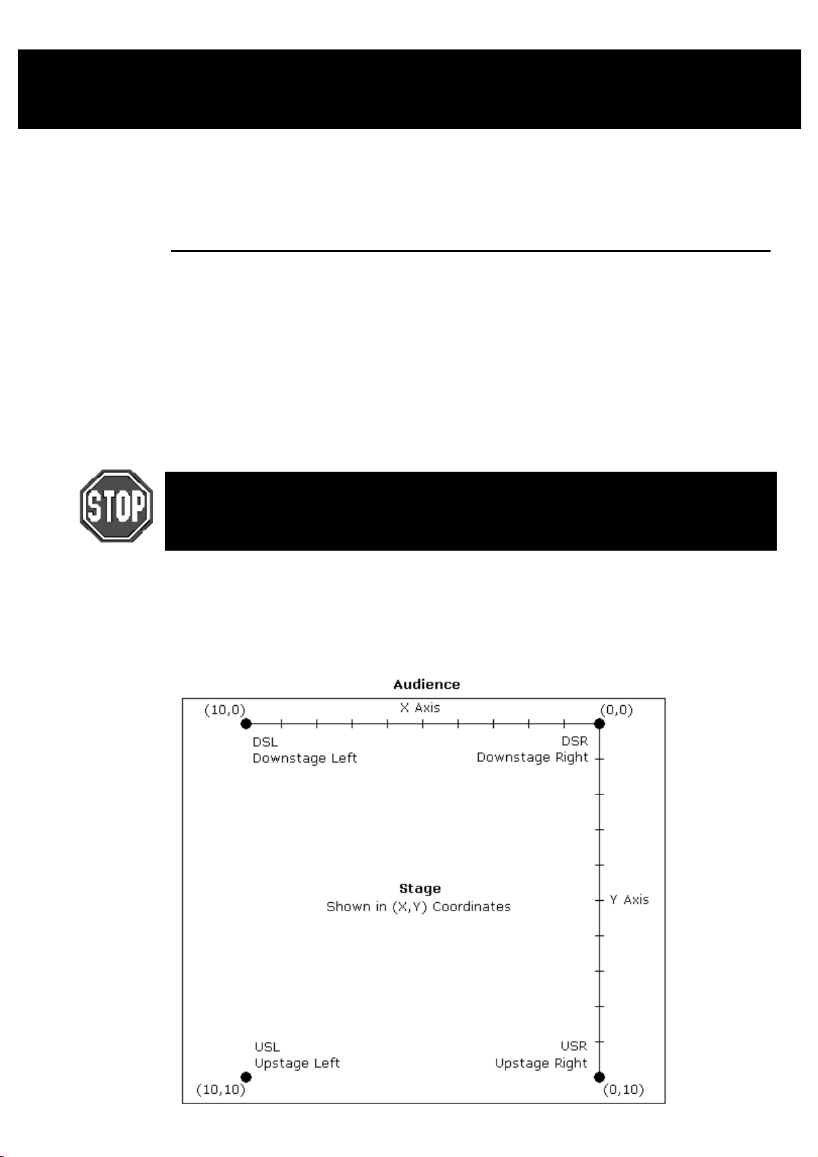
XYZ Mode
This chapter explains hows to program positions in a 3 dimensional space using X, Y, and Z coordinates.
Once you’ve read it, you should be able to calibrate fixtures for use in a 3 dimensional space, program cues
using XYZ coordinates and transfer a stage show from one stage to another with minimal effort. This
chapter assumes that you have patched the console as covered in the previous chapter.
Programming with XYZ Coordinates
Instead of using pan and tilt values for fixtures, it’s possible to prog ram positions in 3 dimensional space
using XYZ stage coordinates. Why is this useful? Let’s say you wanted to aim 100 fixtures at a specific
point on stage. Normally, you’d have to adjust the pan and tilt positions for those 100 lights individually – a
long and tedious process. In contrast, with the XYZ system, all you have to do is enter the XYZ coordinates
on the parameter wheels and the lights will go there instantly. Likewise, if you need to nudge the lights up a
bit – maybe so they hit the top of a mike stand – you only need to adjust the Z parameter wheel and all the
lights will move there together.
If you’re in a touring situation, then the XYZ system can eliminate the daily task of updating preset
focuses. Instead, just recalibrate the lights and all focus p alettes created with XYZ coordinates will n ow be
adjusted for the new venue.
In order to use XYZ mode when programming, fixtures information must come from either
the built in ROM library or from a ver 3.0 or later library file. See Chapter: Fixture Library at
the back of the manual for more information on adapting old libraries or calibrating
fixtures.
Calibration
The XYZ system must first be calibrated before use. This process is simply a matter of aiming every fixture
at each of four calibration points. Accuracy is quite important, so you may want to iris down the fixtures
when aiming, if possible.
The map below shows the X and Y coordinates mapped onto a stage. Z is the height above the stage.
XYZ Mode •••• 51
Page 58
To calibrate fixtures:
1
Choose 4 points of a rectangle on stage which correspond
to the diagram above. The bigger the rectangle, the better.
2
Create four focus palettes – one for each point:
USR Upstage Right X=0 Y=10
USL Upstage Left X=10 Y=10
DSR Downstage Right X=0 Y=0
DSL Downstage Left X=10 Y=0
3
Aim all moving lights at each one of the four points and
record them into the respective palettes.
4
Select each of the four focus points in turn, press Set
twice and then choose the appropriate identifier (eg, Cal
USR).
5
Press Select on the toolbar.
6
Press Calibrate.
7
Press Position twice to change the parameter wheels to X,
Y, Z controls for programming in 3D space.
Note: XYZ information is recorded into palettes, but not into cues. When working in 3D
space, be sure to record all positions into palettes and then build your cues from the
palettes.
Recording Cues with XYZ
XYZ information can only be recorded into palettes, and not into cues. Therefore, it is advisable to record
all XYZ information first as preset focus palettes, and then record these into cues, so that the cues are
updated when the fixtures are recalibrated.
When a cue is loaded for editing, the XYZ parameters are untouched, even though it is using an XYZ
palette. This is correct, and avoids the temptation to modify XYZ in the cue and press update (which would
just copy the hard pan and tilt values to the cue, and break its reference to the palette).
To modify an XYZ position, load and update the palette, not the cue.
Recalibration
If fixtures are moved, they’ll need to be recalibrated to ensure proper performance. In a touring
environment, every fixture will need to be recalibrated every time a n ew venue is reached . In order fo r this
process to work properly, it’s important that the four points be in the same position relative to the stage
elements.
52 •••• HOG – Version 3.20
Page 59

Mini Effects Engine
This chapter covers the Mini Effects Engine both in summary and in detail.
The Mini Effects Engine is a way of creating dynamic effects very quickly. You can use it to make circle
effects, ballyhoos, shutter chases, fluctuating rainbows, and many more.
Previously, to make a dynamic effect, you had to create each static look first, turn them into a chase, and
finally run the cuelist to obtain the effect. Now, on ly a few button pushes will create the same effects within
the programmer. Effects can be recorded into a single cue and can be crossfaded from one to another in
successive cues.
Using the Effects Library
The console comes with a library of pre-recorded effects to make programming as simple as pressing a
button. As an example, to create a circle chase:
1
Select the fixtures for the effect and put them in the
desired intensity and colour settings.
2
Press
3
Press one of the
palette.
Effect
.
buttons in the Effects menu
Circle
(You can also select an effect by opening the Effects Window on the LCD (Press
the cursor keys and
monitor, hold
selection).
A circle chase has now been generated for the fixtures. Now press
effects) to see what it does. If you have trouble finding them, try paging through the Effects palette.
Running Effects Across Different Fixtures and One Shot Effects
To run effects across multiple fixture types or have an effect that runs once and stops, select the fix tures
(several types of fixtures can be selected) and then open the Effects Directory Window as you would
normally in the main LCD and p ress
cursor keys and
1
Open the Effects directory window (hold
Effect
2
Press
3
Select the type of effect setting using the cursor keys
(one Shot settings, or “X’ fixtures of “Y” fixtures per
group).
4
Press
Recording Effects
To record this look as a cue, just press
modify an effect after it’s recorded, load it back into the programmer.
ENTER
Monitor
ENTER
).
NoFX
ENTER
to select the desired effect. To open the Effects Palette on the external
and press the
NoFx
.
on the toolbar to open drop down menu.
to close the drop down menu.
button. Use either the cursor keys or mouse to make a
Effect
Ballyhoo
. Select the type of effect in the drop down menu using the
and press
PIG
Record
as you normally would. A single cue will be created. To
+
PIG
(and some of the other
Effect
) and use
Adjusting Rate, Size, and the Center Point
The rate and size for an effect can be adjust quickly with the left and center parameter wheels.
Certain effects—like circles—use a parameter setting as the center point (or base value). The center point
will be the programmer’s setting for that pa rameter when the effect is record ed. To chan ge the center po int,
either change the parameters that comprise the base value, or to see the centre point on its own, reduce the
size of the effect to 0. You may need to reselect the effect from the palettes once you have changed the
centre point to get the effect working properly again. If a palette is used as the center point, then the effect
will change to reflect changes in the palette.
Effects Engine •••• 53
Page 60
Offset
Offset refers to where in an effect cycle a fixture begins the effect. A single effect can have many looks by
using different offsets. Many of the preprogrammed effects in the Effects window have several
permutations with different offsets depending on the number of fixtures.
Fanning Effects
A quick way to evenly spread the offsets across a range of fixtures is to fan them; hold
the Offset wheel. This can generate some interesting looks. Fan also works on rate and size.
Turning off Effects
To turn off an effect completely:
Select the fixtures.
1
while turning
Set
Press the
2
This will completely remove the selected fixtures from the programmer.
OR
Select the fixtures.
1
Hold
2
or adjust
This will turn one component of an effect off. The side effect is that you will lose all programming for that
component, not just the effects programming.
Real-time effects take up 8 times more memory than a normal static look. This means that
you will be able to store 8 times fewer cues than normal, if all cues were made up of
effects. Bear this in mind when planning your show.
Knockout
and Press
Undo
Parameter
button in the Effects Menu.
Group, Focus, Colour, Beam
wheel.
,
Making Custom Effects
It’s also possible to create effects by combining existing effects and recording the combined effect in a
blank palette position. Effects are usually transferable from one fixture type to another (provided they have
similar parameters), so an effect created on an Intellabeam can be used on a SuperScan.
To make your own effect:
Select your fixtures.
1
Select the desired effects from the Effects pallete.
2
Adjust the offset, size and rate to suit.
3
Press
4
Sometimes the console may not be able to correctly synchronise all your effects in the
programmer (if they have come from many different sources). To resynchronise, turn
on and off.
Base Values
Most of the effects that are provided on the blank show disk are
added to a base value.
You set the base value just like setting up a normal value, using the parameter wheels or by choosing a
palette. This can be done before or after you have selected an effect.
Effects Library
Multiple fixture effects are stored in the Effects Library. You can use the pre-prepared effects from the
blank show disk, or you can record your own combination of existing Effects. Effects Libraries can be
merged from other shows. This way, it’s possible to build up a personal library of effects which are used
from show to show.
Note: A blank show disk contains effects tables and a fixture library, but no palette or cue information.
Record
store the new effect into.
followed by the pallete button you wish to
relative
Blind
. This means that they expect to be
54 •••• HOG – Version 3.20
Page 61

To store a new effect:
Create the effect as above.
1
Press
2
3
The new effect button will store the effects you set up. An IFCB indicator in the palette button will show
what parameter types have been stored.
Effects in the effects menu are not like palettes. They do not auto update.
Record
(eg, intensity in a movement effect).
Choose an Effects button.
, and mask out any unwanted parameters
Effects Engine •••• 55
Page 62

This Page intentionally Left Blank
56 •••• HOG – Version 3.20
Page 63
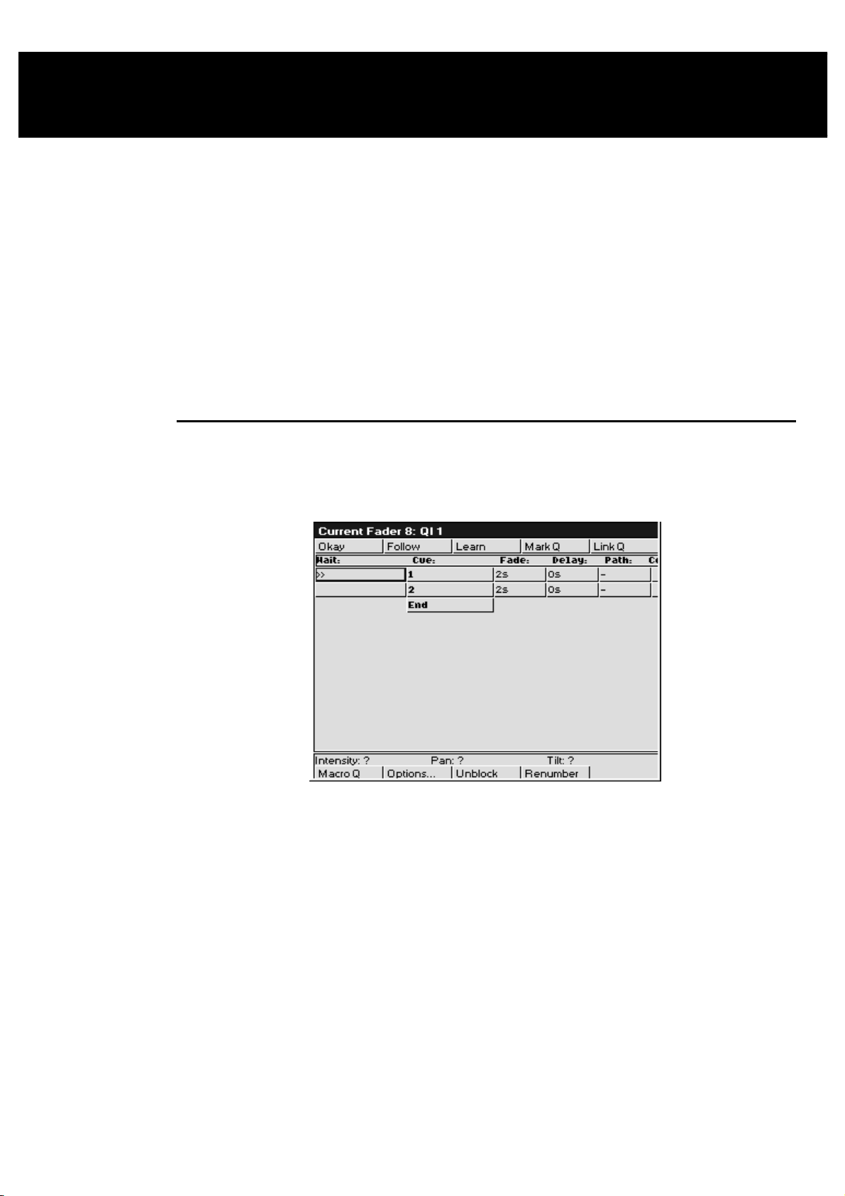
Cuelists
As well as being completely spread out, it’s possible to have an entire show’s programming placed inside
one cuelist, under the control of one Master. To achieve this flexibility, cuelists are designed so that:
Each cue can have many different times.
•
They can run many cues simultaneously.
•
Cues can be triggered manually, after a delay, or by Timecode. Timing can be over-ridden on the fly.
•
Cuelists can contain loops and links.
•
They can be run as chases.
•
All the manual controls can be customised to tailor playback operation to your exact needs.
•
This chapter covers the timing control of cuelists, and the cuelist window functions. Cuelist options are
covered in the
Playback
Cuelist Window
The cuelist window is the key window to see what’s going on in a cuelist. Here, timing is modified, options
are selected, and cue contents are examined. To open a cuelist’s window, hold down the
Choose
for the desired Master.
chapter.
and press
Pig
Or hold
Choose
Window Layout
The Wait column, which is the left hand column of the cuelist window, shows the wait time for cues and
also indicates the current playback state of cues. As we’ll see in the next section, this column is used to
change Wait times.
As cues execute, the cues in this column turn white on the external monitor to indicate they are active. In
addition,
• >>
•
•
•
The Cue column (the second column from the left) shows the cue number and any name associated with the
cue. This column of buttons are also the buttons used for selecting cues during edit operations.
To change a cue number:
Monitor
buttons to select the desired Master:
symbol denotes the current cue.
R
denotes an actively crossfading cue along with a number showing the percentage of the fade
completed.
H
denotes a halted cue.
Pending cues have a countdown to when the cue will execute; this is the wait time.
and press
QList
on the toolbar to view the window on the external monitor and use the
Cuelists •••• 57
Page 64

Open current cuelist window by holding
1
Choose
Select cue by moving the cursor box over its name/number.
2
button of cuelist to view.
and pressing
Pig
Press
3
Type in the new number from the keypad, followed by
4
ENTER
Cue numbers can have up to 4 digits to the right of the decimal (eg, 1.0001).
To change a cue name, type in a name instead of a number.
Continuing from the left side of the screen, the Fade, Delay, Path and Comment columns show timing
characteristics for the cues in your cuelist. Timing can be edited directly using these columns. Special cues
such as Link cues or Mark cues use these columns for other purposes.
The Comment column can be used to either enter a comment relevent to the cue, or to enter Comment
Macros that can be used to control other cuelists. See Macros later in this chapter. Use the
in your comment followed by
Set
.
.
key and type
Set
ENTER
key.
Timing
There are three timing elements for every cue: one wait time, and one or more fade and delay times.
The wait time is the time between pressing the
The delay time is the time in between the cue starting (after its wait has elapsed) and the crossfade starting.
The fade time is the crossfade duration.
The reason there is a distinction between wait an d delay time is th at the wait tim e schedules the execution
of a cue inside a cuelist, whereas the delay time(s) schedule the execution of fades on different parameters
within a cue.
button and when that cue begins to execute.
Go
If you’re feeling confused about waits, delays and fades, look at the following cuelist and then compare it
with the diagram below to see how the cues will react.
58 •••• HOG – Version 3.20
Page 65

Setting the Wait Time
The wait time can only be adjusted using the cuelist window. There are five options for a wait time:
Halt
Wait
Follow
Timecode
Learn
To change a wait time, select a cue’s wait box using the cursor keys, and press
wait time use the keypad to type the amount of time to wait and press
press
Minutes
frame number, distinguished by using a / to indicate 00/00/01.00, hours/minutes/seconds.frames.
Otherwise, pick one of the options from the toolbar at the top of the screen and press
Changing Several Cues at Once.
You can select several cues to change at once. Move the cursor to the start cue, then hold
cursor keys to move the entry box down several wait boxes. The wait boxes will turn dark grey showing
your selection. Then press
boxes you selected.
Setting the Fade and Delay times
Fade and delay times can be adjusted by selecting the appropriate boxes, pressing
time. Again, several cues can be adjusted at once by selecting several boxes together. Times can have up to
two decimal points of precision.
Timing values that are entered in the cuelist window are applied to all parameters of the recorded fixtures.
It is not possible to assign or edit multi-part cue timings in this window. If a multi-part cue time exists, and
you enter a new value in the cuelist window, your multi-part timing structure will be lost.
Represented by an empty wait box; the cuelist stops executing cues and waits for Go.
The cuelist waits this time after the first cue starts before starting this one.
The cue starts immediately after the previous one has ended.
This is discussed in the MIDI and Timecode chapter.
The console monitors the go button for the cuelist and learns the timing based on the button
pushes. This is discussed later in this chapter.
. To enter a standard
Set
. If the time is in minutes,
ENTER
Set
.
and use the
Pig
, and typing in a new
after typing the number, or press
, edit as desired and press
Set
Pig
ENTER
”. Timecode can be entered by typing in a
and “
.
ENTER
. The edits will be applied to all the wait
To edit a multi-part cue timing, the cue must be loaded back into the programmer to modify the timing
using the Time Window.
It’s also possible to enter split fade or de lay times (and split paths) to give different v alues to the fixtures
whose intensities are coming up or going o ut in a cue. Use the / to enter a split time. For example, entering
2/3 in the fade window gives a 2 second fade to the fixtures fading up (the “in” time) time and a 3 second
fade to those fading out (the “out” time).
Learn Timing
You can automatically set up cue wait times by using the
on, every time you press the master’s Go, the console will store the correct wait time for the cues in the
currently selected cuelist. If Timecode is running, it will store the current Timecode frame instead.
The Learn Timing function only over-rides empty (ie. Halt) wait boxes. It will not replace a pre-existing
wait setting.
To use the Learn Timing function:
Learn
function. While this function is turned
Cuelists •••• 59
Page 66

1
Open the relevant cuelist window by holding
pressing the
2
Press
3
Now press the Go button as if you were running your
show. The console will automatically note the times
between your Go button presses and insert them into
your cuelist as Wait times.
4
When you are finished, remember to press
to de-select the function and stop the console from
inserting wait times.
Choose
from the toolbar.
Learn
button on the master.
Learn
Pig
and
again
Special Cues
Mark Q
A mark cue is a setup cue for your cuelist. It takes all of the information from the cue following the mark
cue and executes it as a follow on cue immediately after the previous cue for the fixtures that are at 0%
intensity.
For example:
Cue 1 fades up your fixtures on the drum riser in white.
Cue 2 fades the fixtures’ intensities to 0%.
Cue 3 fades up the fixtures in the keyboard position, and also in red.
When you run these cues in the your cuelist, cue 1 will execute normally, cue 2 will fade the fixtures,
leaving them in the same position; but when you run cue 3 you will see the fixtures move and change
colour as the intensity fades up.
To avoid seeing all of the movement and colour changes, you should insert a mark cue:
1
Select cue 3 by holding down the
pressing the Go or
to the cue.
2
Press
3
4
This time you will notice that when you execute cue 3 the fixtures are already in the correct colour and
position, and so all that cue 3 now executes is the fixtures’ intensity.
If the original cue changes, the mark changes automatically. Pressing
of the
current
Insert Link
There are two ways in which Link cues can work: they can either jump forwards or backwards within a
cuelist and are used to create loops, or to interrupt the normal flow of a cuelist by jumping to a different
point. Note that the cuelist loops back to the first cue by default, so that there is no need to add a link back
to 1 at the end of a cuelist.
Mark Q
You will see a point cue appear between cues 2 and 3 .
Run the cues again.
cue – the one with >> in the wait box. Mark cues only preset fixtures that are at 0% intensity.
.
buttons to move the >> to point
Halt
Choose
button and
Mark Q
inserts a mark cue in front
Pressing
and delay time columns change to
link to.
If you are using a Link cue to jump forwards in a cuelist, then this is all you need to do. No information
needs to be entered into the
If you are using a Link cue to link backwards in a cuelist, and therefore create a loop within your list then
you have some extra options, using the
The count column is used to enter the number of times that you wish to perform the link operation.
Entering zero will leave the field blank, which means that the link (or loop) will run continuously until
interrupted by a press of the Go button.
To edit the value of the
times:
60 •••• HOG – Version 3.20
Link Q
inserts a link cue after the
and
Cue
Count
Count
box.
Count
box and specify your link of cues to loop around a particular number of
current
Count
box.
cue – the one with >> in the wait box. The fade time
. In the
box, enter the cue number that you wish to
Cue
Page 67

1
Move the cursor to the
2
Press
3
Type in a number from the keypad and press
When deciding on the iteration number that you enter in the count box, it should be remembered that the
value represents the number of times that the link cue executes, so if you want your loop to run four times,
you should enter a value of three in the
It is also possible to enter an amount of time in the count box, as opposed to a number of loops. To do this,
follow the same procedure as above but when entering a value, type in the number of seconds followed by
. Adding these values allows the console to determine between time in seconds and number of loops.
.0
Time values within the count box can go up to two decimal points, eg, 12.86 seconds. If you wish to use
minutes rather than seconds, enter the time as described above and hold
minutes are to be used.
Pressing Go during a loop will immediately jump to the first cue after the link cue and continue execution
from there.
A link cue has its own wait time. When a link is followed, the console uses that wait time instead of the
wait time of the cue that it’s linking to.
, allowing you to edit the value within the box.
Set
Count
box on the cuelist screen.
Count
box.
Enter
.
and press “.” to indicate that
Pig
Virtual Masters
Virtual Masters are masters that exist entirely within the desk and are designed to be used when you have
run out of playback masters or need to control a master remotely using MIDI. They behave like normal
masters in all respects except for the fact that they have an extremely limited physical connection to the
user since they have no buttons and no fader. Since they have no fader they default to working at full
intensity.
Virtual Masters are created and assigned as needed. Users can have an almost unlimited number of virtual
masters running different cuelists. Users should note, however, that the more things the desk tries to do at
once, the slower its response will get. If too many cuelists are all running at once then the desk might not be
able to respond quickly enough to more important functions such as sending DMX streams!
To replay a cuelist on a virtual master, the cuelist must not be connected to any other masters:
1
Press List or Macro to bring up the cuelist or macro
directories.
2
Use the cursor keys and ENTER to select the cuelist’s
entry in the cuelist directory.
Or
1
Press List or Macro
2
Type the number of the cuelist and press ENTER.
You will see that the ‘x0’ in the top right hand co rner of the cuelist butto n changes to ‘VM’. This sign ifies
that the cuelist has been connected to a virtual mster. To the left of this will be a couple of other characters.
‘H’ signifies that the cue has halted and is waiting for a Go press, and ‘R’ signifies that the cue is running.
A plain number signifies progress through the cues as a percentage; a number preceeded by a ‘Q’ signifies
that the cuelist is on.
You can only run one copy of a cuelist on a virtual master at a time. That is to say, if you push the button in
the cuelist window a second time it does NOT allocate the cuelist to another virtual master. Cuelists are
only connected to a virtual master if they are not connected to another master of any type. Pushing the
button in the directory window when the cuelist is connected to a master (of any type) has the same effect
as if the cuelist were connected to a normal master and you pushed Go.
Button presses on a virtual master connected cuelist mimic the actions of the buttons found on normal
masters.
When a cuelist running on a virtual master is released the virtual master disappears. Cuelists that are
stomped get released. If the virtual master that cuelist is running on keeps disappearing it is probably
because it is being stomped by another cuelist; selecting the “Persist On Override” op tion will stop sto mpe d
cuelists from being released. Virtual masters disappearing at the end of a cuelist is similar: if the “Stop
Release On End” option is selected the cuelist will b e released once it reaches its end. De-selecting this
option will keep the cuelist connected to the virtual master.
Cuelists •••• 61
Page 68

To release a cuelist or macro running on a virtual master, hold down the cuelist/macro
button on the menu bank and press Release. If you are using an HOG 500, this is not
possible.
Macrocues and Macros
Macrocues are cues that store keypreses and other actions that the user may perform such as mouse clicks
and button presses. When the cue is executed the keypresses or action is regenerated. Macrocues are stored
in cuelists and can be freely mixed with look, link and mark cues that normally make up cuelists.
Recording Macros
Keypresses can be recorded interactively. Keypresses are always recorded into cuelists in the macro
directory. To begin recording keypresses:
1
Or
Press
2
1
2
3
RECORD
Press empty macro palette button.
Press
RECORD
Press
Macro
Type in the number of a blank macro cuelist and press
ENTER
.
.
.
.
All subsequent button presses will b e recorded into the cuelist. If the ‘
in the control panel window is set then the time interval between the previous and current button press will
also be recorded.
Only one macro can be recorded at a time; the console will not allow you to record another macro if a
macro is already being recorded.
Stop Recording
To stop recording:
Press and hold
Press
RECORD
To see the cuelist that has just been recorded press and hold
will appear. Use the cursor keys to place the selection box around the macro cuelist that has just been
recorded and then whilst holding
macrocues that have just been recorded.
Appending To A Macro Cuelist
To append to a macro:
1
2
Or
.
Pig
.
Pig
press
Pig
Press
RECORD
Press the Macro Palette button corresponding to the
cuelist that is to be appended.
ENTER
. A cuelist window will appear that contains the
Learn Macro Timing’
, then press
. The macro window
Macro
Option
You cannot append to a macro that is being played.
You cannot append to a macro if you are already recording a macro.
Replaying Macro Cuelists
Macro cuelists are normally replayed on virtual masters. See the section entitled Virtual Masters for a more
complete description of virtual masters. In general however, selecting an entry in the macro directory or
pressing and releasing a macro palette butto n will run the macro.
62 •••• HOG – Version 3.20
1
Press
2
3
RECORD
Press
Macro
Type the number of the cuelist that is to be appended.
Page 69

Cuelists that are recorded in the macro directory automatically have an option set that stops and releases
them once the end of the cuelist is reached. This allows them to run on virtual masters cleanly and neatly;
once they have completed they release themselves ready to be re-run.
Inserting a Macro Cue Within a Cuelist
Sometimes it is desirable to include a macro command within a cuelist. A macro command is a cue that
causes some action to happen that is not normally included in a cue. For example, holding the
button down and pressing
There are two ways to insert a macro cue, depending upon whether the cuelist is attached to a fader on the
current page or not.
To insert a macro cue within a cuelist located on a fader:
1
Open the cuelist in the Cuelist Window by holding
and pressing the
cuelist.
2
Select the cue following the point at which you wish to
insert the Macro cue by holding down the
button and pressing the Go or
to point to the cue.
>>
3
Press
4
5
Macro Q
You will see a point cue appear before the current cue.
Use the cursor keys and the
cue.
to open the effects window on the external display.
Effect
Pig
Choose
.
button corresponding to the
Choose
buttons to move the
Halt
button to edit the macro
Set
Monitor
Or
To insert a macro cue within a cuelist not attached to a fader.
1
Open the cuelist directory by holding
.
List
2
Open the desired cuelist by using the cursor keys to
highlight the cuelist entry and while holding down the
key press
Pig
3
Select the cue prior to the point where you wish to insert
the Macro cue using the cursor keys.
4
Press
5
6
Editing Macro Cues
Pressing
is selected, and which type of cue is being editted.
Pressing
and replay. At the very bottom of this list are a couple of entries that perform more complex functions that
are difficult or impossible to do with keypresses. These are described in the Additional Functions section.
Set
Set
Macro Q
You will see a point cue appear after the selected cue.
Use the cursor keys and the
cue.
whilst over a macro cue will bring up different editing menus depending upon which column
whilst in the column labelled ‘
ENTER
.
.
button to edit the macro
Set
type
and pressing
Pig
’ brings up a list of key presses that macros can record
With some buttons it is important to know whether the button is being pushed or released.
example of this, it is important to know when the
other buttons operate. Some buttons in the
Pushing
release attributes.
Other entries have coordinates and numbers in the two columns to the right. Pressing
up an edit box that allows you to change their value. Some entries are comprised of two values; both values
should be entered into the edit box separated by a space. The original values will not be updated if the new
values are not understood.
…But I Didn’t Press That Button!
The macro recording code adds a couple of additional cues automatically.
twice on the
SET
column brings up a small menu that can be used to alter the push and
Type
Type
key is pushed and released since it changes the way
Pig
column have ‘
Push
’ and ‘
Release
over these brings
Set
is a good
Pig
’ next to them.
Cuelists •••• 63
Page 70

It will automatically record a
are set up in the correct places for palette buttons and mouse clicks. This does mean that the windows
that are currently onscreen will be lost. If the macro does not contain any palette button presses or
mouse clicks then the
another
View
views.
Load View
option in the control panel window can be used to disable the automatic recording of desktop
cue will be recorded at the point where append ing started. The
Load View
Load View
into the first cue, so that when a macro is run the windows
cue can be removed. If additional key presses are appended then
Don’t Store
Wait For, Empty…
operation, or a record operation. The complex tasks take a small amount of time to complete. The
command waits for the task to complete before proceeding with the next cue in the cuelist. The
For
subsequent cue in the cuelist will autom a tically be set to a halt cue.
Extra cues may also be added at the end of the cuelist to release any keys which were still being pushed
when recording stopped. Typically this is the
recording.
Additional Functions
Load View
menu containing currently stored views. The view that is selected is copied into the cue, so it remains
the same even if the original desktop view is re-recorded.
Load Menu
was started. There is currently no method of editing the contents of this type of cue.
Wait For
The Wait For cue adds the cuelist to a list of cuelists that are waiting, and on ce the process th at is being
waited for has finished a ‘Go’ press is sent to the cuelist. The macro recording cue automatically sets up
the subsequent cue to be a ‘
has to be the ‘
is removed from the waiting list.
Message
the cue.
displays a desktop view. When editing the
updates the contents of the menu banks. This is captured at the point at which recording
is used to wait for a process that takes a substantial period of time, for example
Halt
pops up a warning box. The text used in the warning box is taken from the comment field of
cues are added after key presses which initiate comp lex tasks, eg, a load view
key since the
Pig
Load View
’ cue, although there is no reason why the immediately subsequent cue
Halt
’ cue. If the Go button is pressed at any time then the cuelist proceeds as normal, and
key has to be held in order to stop
Pig
cue you are presented with a
Beacon
Wait
.
Not implemented.
Beep
Warnings On The Use Of Macros
Whilst macros provide users with increased fu nctionality, they can also cause sev ere problems if misused,
possibly to the extent of causing the console to lock up. It is therefore recommended that you have a recent
backup of the show at all times.
Avoid recording key press sequences which leave the desk in an unstable state when replayed. For
example:
Consider the sequence
can’t record another macro whilst recording), when run it will start a macro recording and leave it
recording once the macro has completed. The user may not notice that there is a macro recording for
quite a while, and all the time it is recording every k e y press made.
Macros have no intelligence; avoid recording sequences that access items that are likely to be moved or
deleted. For example:
Consider the sequence where a cuelist is opened by holding
director. Some edit operations are then performed on this cuelist. The cuelist is then deleted fro m the
cuelist directory, and the macro replayed. No cuelist window will be created since the cuelist no longer
exists, and all of the subsequent ed it operations will occur o n whatever it was below, possibly altering
the contents.
Users may also find that macro cuelists run faster than the desk can keep up with; this problem tends to
manifest itself as keypresses being missed out when replaying the macro cuelist. Adding a short wait time
in place of the “
depending upon the number of things the desk is trying to do at once, and the complexity of the task
initiated by the preceeding keypress, but times of no more than half a second usually suffice.
Follow On
RECORD, Macro
” command will solve this problem. The size of the wait required varies
, xx,
ENTER
. Whilst this does nothing when recording (you
and selecting an entry in the cuelist
Pig
Saving Macros
Since macros mimic user inputs and input devices vary between hardware platforms, ie. The HOG 1000
and 500 don’t have touchscreens whereas the WHOLE HOG II does, the HOG 1000 has more faders that
the HOG 500 etc, macros are not portable across the different hardware platforms. Macro cues that are
64 •••• HOG – Version 3.20
Page 71

loaded onto a different hardware platform from the one they were created on will be converted into blank
cues. The comment field of the cue contains the name of the button that was in the macro cue in case you
need to reconstruct the macro on the new platform. If the show is saved on the new platform then all of the
original macro data will be replaced by the blank cues.
When saving as a v2.3(32) show, macro cues are converted to blank cues with the name of the button that
was in the macro cue in the comment field. The macros directory is not saved when saving as v2.3(32).
Macros are platform specific. You cannot transfer them between different platforms!!
Cuelist and Macro Directories
It is now possible to directly record to cuelists in the Cuelist Directory. Pressing
selecting a button in the Cuelist Directoy will record a cue onto the cuelist that corresponds to the button
that was selected. If the button does not contain a cuelist then a blank cuelist is created, and a cue is
recorded into it.
The Macro Directory operates in an identical manner except that it is accessed through the Macro key
rather than the List key. Cuelists can be copied freely between the cuelist and macro directories, and the
masters. Recording to a cuelist in the cuelist directory will store a look cue, recording to a cuelist in the
macro directory will store keypresses and other user action. Move the cuelist between directories to record
different types of data onto the same cuelist.
Editing Cuelists
Holding
cuelist. Since the cuelist is not necessarily connected to a master some of the options may be unselectable.
These options will also remain greyed out if the cuelist is connected to a Virtual Master.
and selecting a cuelist in the Cuelist Directory Window opens a cuelist window for that
PIG
RECORD
followed by
It is possible to insert Mark, Link and Macro cues without the cuelist being connected to a master. If the
cuelist is connected to a master then the cue is inserted at the current cue (the one with >> in the wait box).
If the cuelist is not connected to a master then the cue is inserted at the selected cue (the one with the
outline around it). Mark cues are inserted before the cue, link and macro cues are inserted after the cue.
Comment Macros
Comment Macros have been designed for triggering the Go,
as well as changing page from within a currently running cuelist.
The Comment Macro commands are typed into the comments box of a cue using
the far right hand column for a cue in the cuelist window. They execute when the cue starts. If you don’t
have a cue at an appropriate point, record a blank cue.
The available commands are:
G Go
S Halt (S
R Release
P Page
T
- use this by specifying G and the number of the master which you wish to press the Go
button for, eg. G2 to Go the second Master.
is for stop), eg. S2 to Halt the second Master.
, eg. R4 to Release Master 4.
(Use the page numbers shown in the page window), eg.
12.1.
GoTo cue, T followed by a decimal number does a “goto cue#” on the currently selected
master. eg,
will goto cue 3.2 on the currently selected m a ster.
T3.2
Halt
, and
Release
buttons for other masters,
. The comment box is
Set
P12.1
to change to Page
C
J
K
L
M
To distinguish the Comment Macro from a normal comment, it is preceded by >. Multiple Comment Macro
commands can be separated on the same line by :. A range can be triggered using >.
For example,
Select current master - C followed by the master number selects that master to be the
current master, eg, C5 to select master 5.
Release a Virtual Cuelist, eg, J6 to release Virtual Cuelist 6.
Release a Macro, eg, K9 to release Macro 9.
To mimic a Go button push on a Virtual Cuelist, eg, L6 will hit Go on Virtual cuelist 6.
To mimic a Go button push on a Macro, eg, M9 will run Macro 9.
>G2:G4>G7
triggers Go buttons on Playback Masters 2 and 4 through 7.
Cuelists •••• 65
Page 72

Cuelist Contents Window
It is only possible to view this screen if you have an external monitor connected to your HOG. To view this
screen, hold
selected cuelist:
Monitor
and then press
Content
on the toolbar to open the cuelist contents window for the
This window shows what is programmed in the current cue of a cuelist. If you use Go or
or down the cuelist, the window will change to show the new current cue. You can use the << & >> screen
buttons to over-ride this and look at another cue without changing cuelist position. Access them and the
other screen buttons by pressing
on screen reading from left to right. To view a specific cue, make sure the console is in monitor mode (the
red led in the
in the cue number and press
Alternatively, if you have a mouse or trackball connected to the console, you may use the mouse pointer to
click on the buttons on the external monitor. The mouse/trackball MUST NOT be in PAN/TILT mode for
this function to work.
Only programmed values are actually shown in the display, and they are displayed in different colours:
Black
Red
Green
White
In addition, the programmer contents overlay themselves over this window to aid programming:
White fixture number
Blue background
Selecting the
will hide the values in the programmer that have a blue background, and display the contents of the cue in
the text colour to suit the conditions of that value. Fixtures in the programmer will still have the white
background behind the fixture number.
Monitor
Programmed in the displayed cue but unchanged from previous cues.
Parameters changed from the previous cue; Intensity levels going up.
Intensity levels going down from the previous cue.
The level was programmed in a previous cue, and is not changed in this cue.
Hide Prog
button is lit and the header bar on the ex ternal monito r is blue) and pr ess
Enter
button with the mouse/trackball pointer or by pressing
and numbers 1 through
Pig
.
The fixture is selected in the programmer
The level is set in the programmer
on the keypad with respective to the buttons
8
and 8 on the keypad
Pig
to move up
Halt
Set
. Type
Other Cuelist Window Functions
Cuelist Options
This button opens the Cuelist Options window, which is described in the Playback chapter of this manual.
Follow
On the cue list menu bar you’ll find
Scroll Lock on a PC. With Follow selected, the cuelist window holds the current cue in the middle of the
screen as you go through the cue list. With Follow de-selected, you are free to page up and page down
through the cuelist window as you wish.
Unblock
Use
Unblock
from cues.
66 •••• HOG – Version 3.20
Follow
to eliminate hard commands (programmed parameters that are the same in a previous cue)
which toggles in and out of “screen lock” mode, similar to
Page 73

Press
1
2
Unblock
Select the cues to unblock.
from the cuelist toolbar.
Press
3
Renumber
Pressing
if you have mixed up the fixture numbering and you wish to bring some semblance of order to the fixture
numbering.
Renumber
1
2
3
ENTER
in the bottom cuelist toolbar renu mbers the subseq uently selected cues. This is useful
Press
Renumber
Select the cues to renumber.
Press
ENTER
.
from the cuelist toolbar.
.
Cuelists •••• 67
Page 74

This Page intentionally Left Blank
68 •••• HOG – Version 3.20
Page 75

Playback
The HOG is designed for maximum playback flexibility:
Cuelists provide powerful timed playback for theatrical shows. They can be fully integrated with
•
Timecode inputs from MIDI, triggered via MIDI show control, or MIDI notes.
Masters running independent cuelists can be operated simultaneously to control unstructured shows.
•
Immediate access to fixtures via the programmer, or to looks and chases via masters.
•
An instant and crossfading page changing system simplifies page changing down to one button push,
•
and allows set list changes at the last minute.
10
8
6
4
2
0
FLASH
MASTER
MASTER
GRAND
GRAND
1 2 3 4 5 6 7 8 9 10 11 12 13 14 15 16
1 2 3 4 5 6 7 8 9 10 11 12 13 14 15 16
FLASH
Masters
The Masters are the bank of faders and buttons located to the left of the programmer. Each Master has the
power to control a complete cuelist, a single chase, or a single cue; all of them can be run simultaneously or
in any combination.
Each Master includes four buttons and a fader. They are, from top to bottom:
Choose
Used to select the master during programmer mode, and to set the master as
selected master is the master that is controlled by the Central Controls. It is also the master
that is the default destination for programming operations, eg,
Go
Press Go to start a cue fading and start the cuelist executing cues (running). If the cuelist is
already running, press it to skip cues or to exit from loops.
Halt
Instantly halts any crossfading cues, and stops the cuelist from running. Pressing Go will
resume fading and execution of cues. Once a cuelist has been stopped with an initial
button press, pressing
Fader
Fades the cuelist’s intensity. You can conf igure the cu elist so that its inten sity is controlled in
an HTP or LTP fashion. You may also assign the fader as an ICBF fader which controls all
parameters rather than just the Intensity parameter.
Flash
Bumps the cuelist’s intensity to full. You can configure the cuelist so that its intensity is
controlled in an HTP or LTP fashion.
Alternate Actions
Holding down the
Choose + Go
Choose
Choose
Choose
+
+
+
Halt
Flash
Fader
etc.
Choose
Record, Copy,
again fades backwards through the cuelist.
Halt
button while using a Master’s controls will give different actio ns:
Step to the next cue without fading and without starting the cuelist running.
Step back to the previous cue without fading and without starting the cuelist
running.
Activates the master. This is like pressing Go, but the cuelist does not start
executing cues, and stays on the same cue. Use it to reassert a master that’s been
over-ridden.
Manually crossfades all the cuelist’s programmed parameters.
selected
. The
Halt
Playback •••• 69
Page 76

DBO
Other Playback Controls
Grand Master
The Grand Master is the overall intensity control for the entire console. Most often, it’s simply left at full.
Only intensity parameters are controlled by the Grand Master; it has no impact on colour, beam or focus
parameters.
DBO
The Dead Black Out button sits above the Grand Master. When pressed, it immediately brings all intensity
levels to 0%, where they’ll remain as long as the button is held down.
Release
Note that any changes caused by the Grand Master fader or DBO button are intentionally
NOT reflected in the Stage Output display. If the display changed then you would have no
reference as to what would happen when you restore the console to 100% output.
Turning Off a Fader—Releasing
Pulling down a fader only forces pro grammed intensities to 0%, all the other parameters of a fixture will
remain active. To release
select the cuelist master by pressing its
to immediately restore light to the stage.
DBO
parameters of any particular master so that they have no effect on the output,
all
Choose
button and then press
Release
.
To release all faders at once, press
Goto
To jump straight to a cue, and start the cuelist running on the currently selected master:
Press
1
Main Display).
Enter the cue number to jump to, say 45.
2
Press
3
will use the fade time of the incoming cue.
Manual Crossfades between Masters
To crossfade between several masters:
Make sure that the incoming master’s fader is at 0%. Hold down
1
the
Choose
Pull down the faders of the outgoing masters. At this point, NO
2
fades will occur.
Move up the incoming master’s fader. This will now perform the
3
crossfade between the outgoing masters and the incoming master.
Release the
4
Note: This will not work if any of the faders are set as ICBF faders.
button (located on the Left Hand Side of the
Goto
ENTER
to execute a fade to the destination. The console
button of the incoming master.
Choose
plus
PIG
button
Release
.
Over-riding Programmed Timing
All programmed timing throughout the console can be manually over-ridden using the Console Rate
control. This console-wide rate control is accessed by holding down any
right parameter wheel (
console will run exactly at their programmed time. The rate shown is expressed as a per cent; thus, 200%
means that all times will be twice as long as their programmed value, and 50% means that all times will be
half as long, although all times will be adjusted proportionally. As the Console Rate can be accessed from
any
Choose
using another
There is also manual over-ride for individual playback masters called
master’s
cuelist’s timing rate.
To manually adjust a single Cue’s rate, use the
Choose
the next to go) and is automatically reset to 100% when the fade completes. Thus a fade can be slowed
down or shortened without the effect persisting to other fades or other masters.
70 •••• HOG – Version 3.20
Choose
Console Rate
button, it is possible to edit the value using one
Choose
Choose
Button and adjust the left parameter wheel. This relates to the current fade (either in progress or
button, even if it’s on a different page.
button, and turn the middle parameter wheel (
). With the Console Rate set at 100%, all of the cues within the
Choose
Single Q Rate
button and then adjust it back again
Cuelist Rate
Cuelist Rate
function by holding down the master’s
button and turning the
. Hold down the
) to adjust a single
Page 77

Note that the percent value relates to the length of the fade. So increasing the percent
value increases the length of the fade and vice-a-versa.
Master Precedence
Because the console can simultaneously run sixteen (or eight) separate cuelists on faders and more on
virtual masters, there is possible conflict over which master actually has control of a parameter. In order to
decide which master has control, the console applies the following rules:
For focus, colour and beam parameters:
The console uses Latest Takes Precedence (LTP). This means the most recently activated masters will
•
override earlier masters (Note: Only the specific conflicting parameters are over-ridden; nonconflicting parameters on the earlier masters will be left untouched).
Releasing overriding masters will return the overridden parameters back to the control of the old
•
masters.
Masters which are fully over-ridden (ie. all programmed parameters have been over-ridden by other
•
masters) are released automatically as soon as all parameters are over-ridden. This is called stomping.
The Programmer always has priority over the Playback Masters (remember, you can press
•
suspend Programmer output).
For intensity parameters:
By default these are also controlled by LTP, but you can set cuelist options to make a master work in a
•
Highest Takes Precedence (HTP) fashion. In this case the con sole will output, for a particu lar intensity
channel, the highest programmed value of all the HTP masters and the highest priority LTP master.
Cuelist options exist for fully customising the p riority scheme for a cu elist. See the Cuelist Options section
of this chapter for more information.
What is an Active Master?
An active Master is a master that has had Go pushed, has been manually faded up, or has been activated
using
Choose
Masters, once activated, remain active until they are either fully over-ridden and thus stomped
(automatically released), or they are manually released. Partially over-ridden masters are still active, and
thus still control the remaining, non-over-ridden parameters. Cuelist options exists for customising this.
Playback Master LEDs
The Masters’ LEDs give feedback as to the active and over-ride status of a master.
LED Solid Flashing
Go
Halt
+
Flash
.
Executing Crossfade Crossfading, but fully over-ridden
Controlling Colour, Beam All CBF over-ridden, or no CBF
Blind
to
or Focus Parameters
Flash
Default Values
When no playback masters are active, and nothing is selected in the Prog rammer, the console will output
the default values for each parameter of every fixture. These values may be modified in the fixture library
of each individual fixture.
Controlling Intensity All I over-ridden, or no I
Customising Playback with Cuelist Options
Hold
cuelist toolbar to customise the response of a Playback Master. Chase options are covered separately in the
chase section.
and press a
Pig
Choose
button to open the cuelist window for that master. Press
Options
Playback •••• 71
on the
Page 78
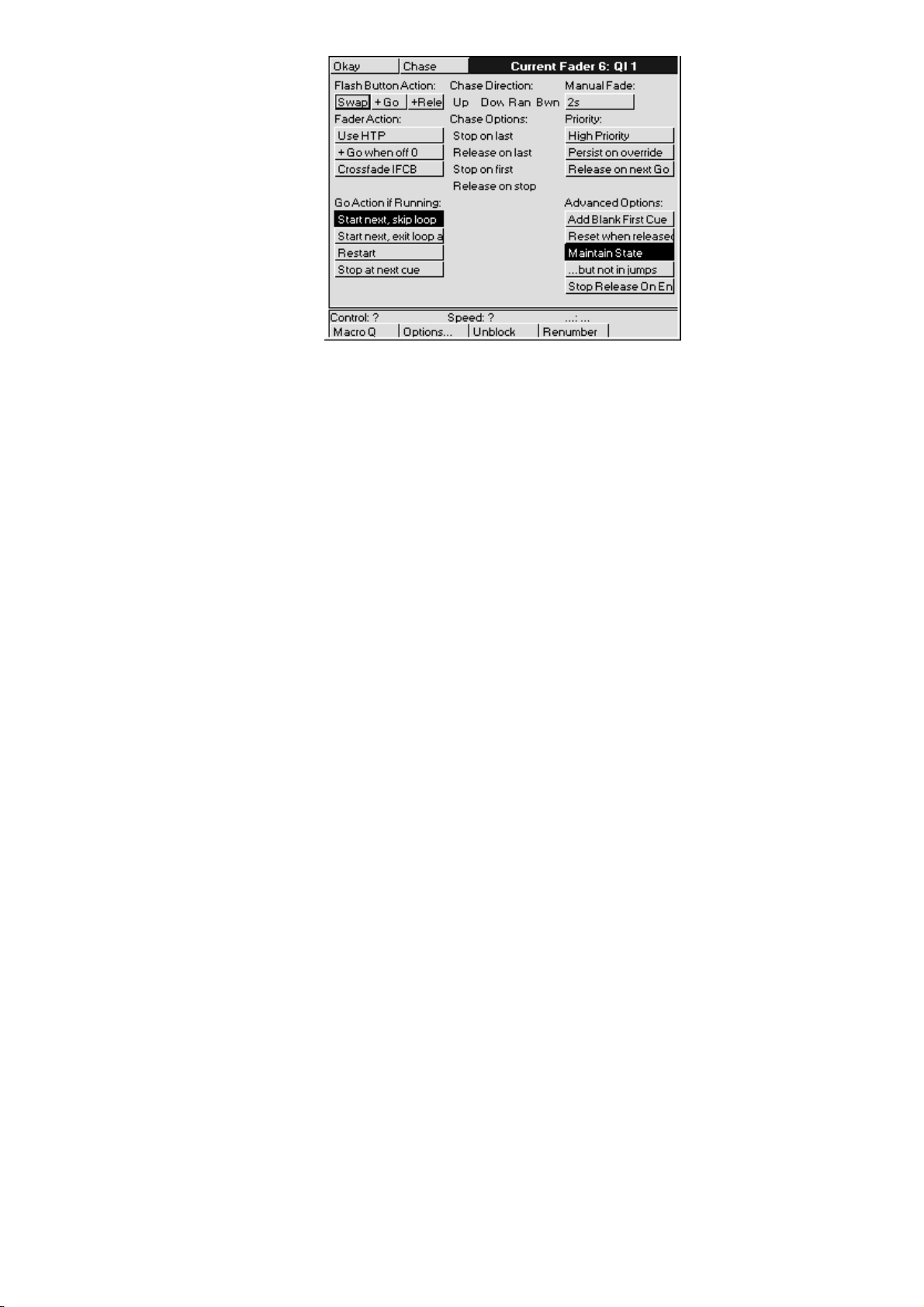
All these options are stored in the cuelist. If you change to a different cuelist (by changing page, for
example), the option settings may chang e and the Master will behave differently.
Flash Button Action
Flash buttons are the buttons found below the row of faders, and are useful for bumping Intensity on and
off. They can also be set up to operate one of the following ways:
Swap
+Go
+Release
Fader Action
Faders are used for controlling Intensity levels. Intensity from different masters is combined together
according to the options set for each cuelist:
Use HTP
+Go when off 0 Go
Crossfade IFCB
Go Action if Running
These options determine what happens when the Go button is pressed while a cuelist is already ex ecuting
cues.
Start next, skip loop
Start next, exit loop at end
Restart
Stop at next cue
Pressing one Flash button turn s the others off. Normally, Flash button presses are additive.
Pressing the flash button will also press Go.
Pressing the flash button will also release the cuelist.
Sets intensities to Highest Takes Precedence (normal operation is Latest
Takes Precedence).
is also pressed automatically as soon as the fader is moved from
zero.
Sets fader to control all parameters (ICBF) within the cuelist.
Starts next cue immediately. Or, if the cuelist is in the middle
of a loop, it goes immediately to the first step after the loop.
Starts next cue immediately. Or, if the cuelist is in the middle
of a loop, it completes the loop before moving on.
Restarts the cuelist at the first cue when Go is pressed.
Finishes fading the current cue, and stops at the next cue. In
contrast,
freezes the current cue instantly.
Halt
Manual Fade
This is the fade time used by the cuelist for all manua l o perator activity, namely
This fade time is also used for fading operations where no other appropriate time exists, namely fades for
jumping inside a cuelist, where the parameters are not in the immediate next cue (ie, the fade time used for
resetting the ‘state’).
Priority
Latest Takes Precedence cuelists can be prioritised manually to prevent certain masters over-riding others.
If there is a conflict between two cuelists sharing the same p r iority level, then normal LTP rules apply.
72 •••• HOG – Version 3.20
Releasing.
•
Jumping to different parts of the cuelist using
•
•
Using
to go backwards.
Halt
Goto
.
Page 79

High Priority
Release on next Go
In normal operation, the console automatically releases masters that have been fully over-ridden (a process
called ‘stomping’). This is to make it easier for you to see what is actually active. However, in certain
circumstances this is inconvenient, so it is possible to prevent this from occurring.
For high priority. Use this to make sure that something won ’t get over-
ridden.
For low priority. The cuelist releases automatically when another fader is
activated, even if not fully over-ridden.
Persist on override
Advanced Options
Further options designed to get the cuelist to respond the way you would like.
Add blank 1st cue
Reset when released
Maintain state
but not in jumps
Stop Release on End
Prevents the cuelist from getting stomped. This way, you can return to
looks on this master when other masters are released.
Inserts an empty cue at the start of the cue list, as a safe place for the
cuelist to rest before starting, or after the last cue in the list has been
executed. This is useful when you want to start with the first cue, but
don’t want to have to release the master to do so. This function is turned
on automatically when timecode is used.
Resets the cuelist to the first cue when released. Normally, the cuelist
will remain on the current cue, and will restart there if you press
again.
The cuelist automatically outputs the cumulative effect of all its cues
(the state), even though only changes are recorded in cues. If this option
is not selected, then only the information specifically programmed in
each cue will be output when that cue is active.
If
recalculated to reflect the programming in the jumped cues.
Cuelists that are recorded in the macro directory automatically have this
option set to stop and release them once the end of the cuelist is reached.
This allows them to be run on virtual masters cleanly and neatly; once
they have completed they release themselves ready to be re-run.
or a link cue is used to jump to a n ew cue, the state will no t be
Goto
Go
All these options are stored in the cuelist. If you change to a different cuelist (by changing page, for
example), the options may change and the Master will behave accord in gly.
Chases
Chases are nothing more than cuelists with the timing over-ridden. Each step of the chase is a cue in the
cuelist.
To create a chase:
Record a series of steps just like you would to create a cue list.
1
Open the cue list
2
and press
Pig
toolbar).
Press
3
Chase Timing
A chase plays back its steps (cues) using beats per minute (BPM) to control the rate, and crossfade % to
control the amount of fade between steps.
There is no upper limit on rate nor crossfade %. A crossfade of 0% means that the chase will snap change.
A crossfade of 100% means that the chase will fade smoothly from step to step, with no intervening
stationary time. A crossfade of 200% means that only half the crossfade will be completed before moving
onto the next step.
Chase
Options
Choose
. Your cuelist has now been turned into a chase.
window on the cuelist toolbar (hold
button, then press
Options
on the
To adjust rate and crossfade:
Playback •••• 73
Page 80
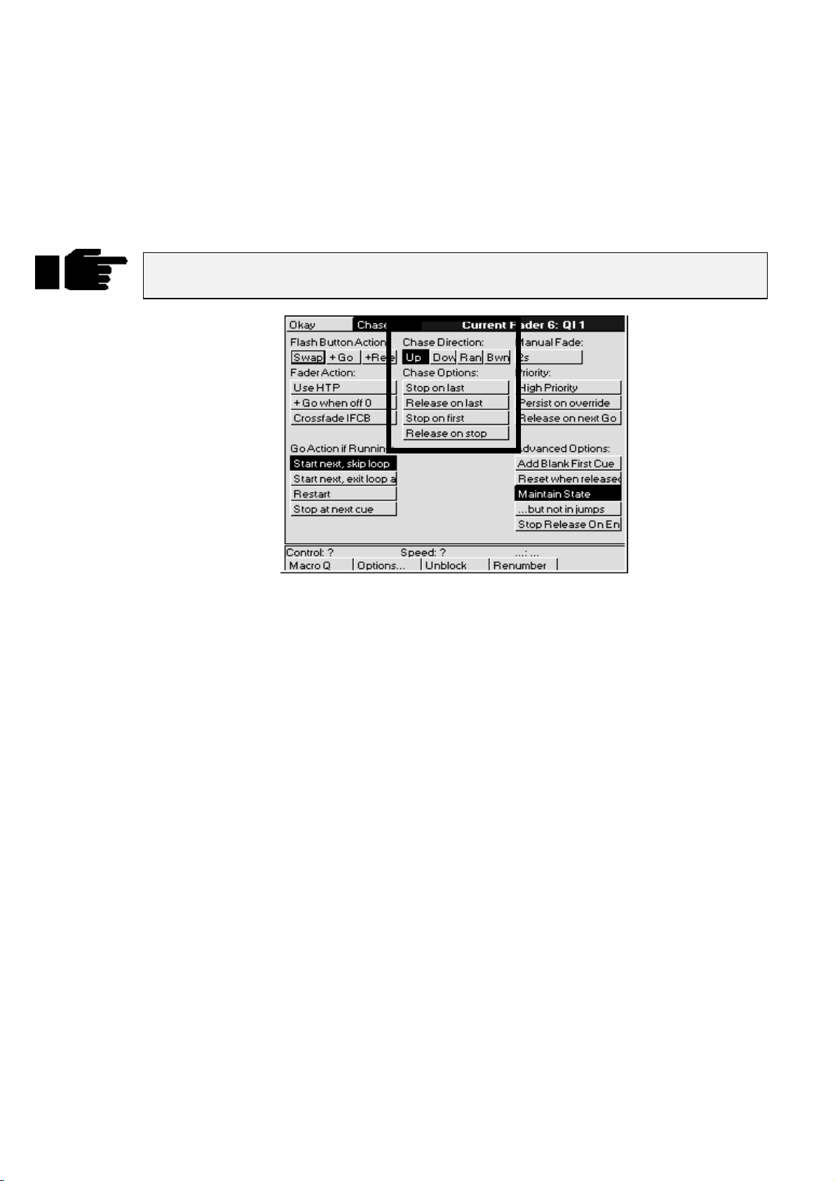
Hold down the master’s
1
display will change to show
becomes the
Adjust the left (Rate in Beats Per Minute) and centre (Crossfade
2
in %) parameter wheels.
console rate
Choose
, a console-wide rate control).
button. The parameter wheel
Rate
and
Fade %
(the right wheel
When you are happy, just let go of the
3
settings that you have made will be stored automatically. You
need press no other buttons. If you wish to re-adjust the values at
any time, just hold the
values as before.
Cues inside a chase do not have to have simple default fade and delay times. You can
adjust them parameter by parameter as though they were a normal cue.
Choose
Choose
button down and adjust the
button and the
Chase settings
In the
options window
Up
Down
Ran
(Random) The chase randomly picks the next step.
Bwn
Normally the chase loops continuously. To change this:
Stop on last
Release on last
Stop on first
Release on stop
, you can select the chase direction:
The chase runs from the first to the last step.
The chase runs from the last to the first step.
(Bounce) The chase runs from the first step to the last, then back to the first, etc.
: Executes the chase once and then stops.
: Runs the chase once and then automatically releases it upon completion.
: Runs the chase once and then returns to step one and stops.
: Releases the chase when
Halt
is pressed.
74 •••• HOG – Version 3.20
Page 81

Saving and Merging Shows
Often you will want to store your show onto floppy disk. In addition, you may want to merge old
programming from earlier shows into your current shows. Or, if you have been programming a show with a
colleague on a separate console, you may want to combine the two shows together for playback on one
console.
This chapter explains how to use floppy disks to do these things.
Saving a Show
To save a show:
Press
1
Insert a standard 1.44 MB 3 1/2 floppy disk into the disk drive in
2
the side. The disk need not be formatted.
Press
3
Press
4
list the items it’s saving as it goes along.
okay
your show is larger than can be stored on one floppy disk, you
may have to delete unused cues/lists in order to save it.
Press
5
. You will see the usual setup toolbar.
Setup
Save Show
Okay
appears when everything has been copied to the disk. If
Okay
.
to confirm the save. A progress window will open and
Save finished
to finish.
Change Show Window
More advanced floppy disk functions are accessed through the
toolbar.
When you open the window, it automatically tries to read the catalogue information off a disk in the disk
drive. If none is present, you will get an error message. This can be ignored safely. It is okay to open the
window without a disk in the drive.
window, opened from the
Shows
Setup
Changing to a Different Show
If you change to a different show, make sure that you have saved your current show, since
you will lose all of its programming.
To load a different show from floppy, insert the show disk and press
you to confirm that it is
to lose the current show. Then a progress window will open that lists each
okay
Load Show
Saving and Merging Shows •••• 75
. The console will ask
Page 82

item as it is loaded.
Press
Naming a Show
To avoid mixing up disks and accidentally overwriting a different show, give your show a name before
saving it.
To name a show, use the cursor keys to select the box labelled “Name of current show in memory”, and
press
The floppy disks on which the shows are saved are labelled with this name plus a number. The number
refers to the disk number. 1 for Disk 1, 2 for Disk 2, etc. If you ever need to change a disk’s label (such as
when using a show downloaded from the Internet), use a Windows PC (File Manager, Windows Explorer),
or DOS (label a: ), or a Mac.
Format
To format a disk, insert it into the drive and press
It’s a good idea to periodically reformat your disks. Disks can develop bad sectors;
reformatting can spot this and prevent you from losing data. Reformatting will erase the
contents of the disk!
Verify
If you’d like to be sure that your show has been properly saved to disk, turn on the Verify option in the
toolbar. When it’s on, the console checks the disk while saving to confirm accuracy of the save. Saving in
this mode takes about twice as long as a normal save.
to return to the shows window. Press
Okay
and type in a name.
Set
Load Finished Okay
appears when everything has been loaded successfully.
to exit shows window.
Okay
Format
followed by
Okay
.
Merging Shows
Using the Change Show window, you can select items from a different show and merge them into your
current show.
To merge items into your new show
Insert into the disk drive the floppy containing the show you are
1
merging
Open the
2
the Change Show window will not show what is in your disk, so it
will not be possible to pick items for merging.
Pick items for merging from the merge list below th e toolbar by
3
selecting them with
automatically as soon as you pick something that depends on
them.
Press
4
progress of the merge.
If you merge in a cuelist, but don’t merge in associated palettes, you have to make
absolutely sure that the cuelist has been programmed using the palettes that are already
programmed in the console. If the console cannot find a palette when it merges in a cuelist,
it will ignore all programming associated with that palette.
from
.
window. If you do this before inserting a disk,
Shows
ENTER
. A progress window will open to show you the
Merge
. Note: the palettes will be selected
There are four options for merging palettes:
Merge matching palettes
Replace matching palettes
Append matching palettes
76 •••• HOG – Version 3.20
Information from the palette on disk an d the palette in memory
is merged together. The palette information from disk takes
precedence if they clash.
Information for the palette in memory is completely erased,
and the information from the palette on disk is put in its place.
The palette on disk is appended at the end of the palette
directory. The existing palette in memory is left untouched.
Page 83

Match by name only
Normally, palettes are matched on the basis of their names. So
if a palette in the show on disk has the same name as a pa lette
in the show in memory, they will be matched together.
Obviously this won’t work if you have different palettes in the
same show with the same name (eg, two palettes called “red”).
If this is the case, you can try turning off the option “Match by
name only”. The console will then match palettes if th ey have
the same name AND they both came from the original show –
ie. a show which was saved onto two disks, then each disk was
loaded, edited and saved separately, and now the two are being
merged back together again.
Don’t turn off “Match by name only” if you are trying to merge palettes that come from
different shows.
How to Combine a Show That Has Been Programmed on Two Consoles
There are two approaches:
Split the programming into fixtur es. eg, on e console d oes dimm ers, while the o ther do es cyberlig hts. To
•
merge, save the cyberlights component to disk, add the cyberlights to the dimmer console’s schedule,
then merge all the Cyberlight palettes, cuelists, and pages into the dimmer console.
Split the programming between cuelists. For this to work, each console must start with the same setup
•
and palettes
loading onto the other console. From then on, parallel programming of cues and cuelists can occur.
When you come to merge back into one console, just select cuelists to merge. Do not merge the palettes
back, since you will end up duplicating existing palettes, with some cuelists using one set, and the
merged cuelists using the other.
. This is best done by setting up and making palettes on one console, then saving to disk and
Saving Shows as Previous Versions
There are occasionally times when you may wish to save a show as a previous version, for instance, you
may wish to save as version 2.3 (build 32) so that you can load the show into a Jands Hog. Pressing the
Save As
keys to select which version you wish to save the show as and hit
When saving shows as versions that are older than version 3.2 (build 116), you will need to use fixtures that
were loaded from a fixture file on disk rather than fixtures that were part of the ROM library built into the
console. If you try to save a show containing fixtures from the ROM library as an old version, you will get
an error window pop up with the following message: “Fixture types from ROM library cannot be saved in
this format. Remove the following types before trying to save as this version:” followed by a list of fixtures.
button on the toolbar will display a selection of choices to save your show as. Use the cursor
ENTER
.
If the fixtures in your patch were loaded from the ROM library, you will not be able to save
them into shows saved in formats 3.2 (build 114) or earlier.
Saving and Merging Shows •••• 77
Page 84

It is recommended that a show is also saved normally. A show saved as a previous version
may not retain all features of your show.
Creating a New Show
To clear the console and start with a fresh blank show, there are three ways to proceed:
You can press New Show in the start up window when the console is turned on.
•
You can press New Show in the Change Show window.
•
Or you can load a blank show from a floppy disk by pressing Load Show in either the start up
•
window or the Change Show window.
You do not need to have a fixture library in the disk driv e as the console has a bu ilt in ROM library. If yo u
are using custom made fixture files or wish to save the show in an older format, you will need to use a
fixture file from disk, and hence you will need to load a blank show.
78 •••• HOG – Version 3.20
Page 85
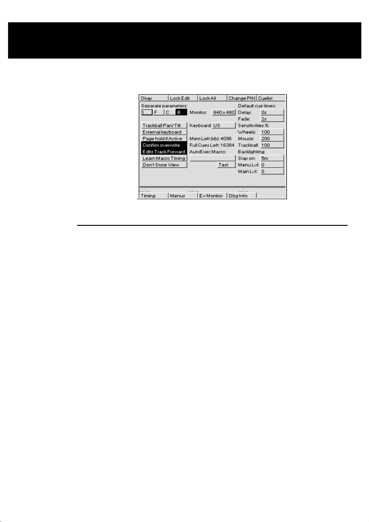
Customising the Console
The HOG’s settings can be customised to fit your requirements. This customisation is done using the
Control Panel window.
To open the Control Panel window, press
Setup
followed by
Panel
.
Programming and Playback Defaults and Settings
Separate parameters
Trackball Pan/Tilt
External keyboard
Page Hold if Active
Confirm Overwrite
Edits Track Forward
Learn Macro Timing
Don’t Store View
The HOG treats certain parameters as a group; for example, it
normally makes sense to record colour mixing parameters (Cyan,
Magenta and Yellow) as a group. However, many times you don’t
want a parameter such as Beam recorded as a group. If it were, you
couldn’t have a gobo chase operating simultaneously with an iris
chase. The default is Beam parameters recorded independently, and
others grouped. To change the way in which the parameters are
recorded, use the cursor keys and
relevant parameters (dark grey background indicates that the
parameters are to be recorded seperately).
Allows a mouse or trackball to set pan and tilt values without having
to press
on screen mouse with this option. Use this mode to simplify control
of X and Y parameters when programming fixtures.
If you’ve plugged in a keyboard, use this button to prevent the
internal keyboard from popping up in the menu banks on an HOG
1000 and allow the external keyboard to be used instead.
This option lets you hold over active cuelists during a page change
to the a new page without having to hold down the
This option presents a confirmation dialog box (
Replace
This option sets the d efault for tracking of cues through subse quent
cues. With
changes through the subsequent cues until there is a change
programmed. This is the normal programming mode. With
Track Forwar
cues will remain until the cue finishes, at which point the changes are
undone in the next cue.
If this option is set, then the time interval between commands will be
recorded when macros are being recorded.
This option can be used to disable the automatic recording of
desktop views when recording a new macro.
Position
,
and use the parameter wheels. You cannot use the
Merge
) when a cue is about to be overwritten.
Edits Track Forward
off, (also known as “Q only” mode) all edits to
d
ENTER
key to select/deselect the
Choose
on, a cue will track its
button.
Insert
Edits
,
Customising the Console •••• 79
Page 86

Monitor
Keyboard
Mem Left (kb)
Full Cues Left
AutoExec Macro
Test
Default Fade & Delay times
Wheels %
Mouse %
Trackball %
Stay on
Menu Lvl
Main Lvl
Set the time after which the backlighting turns off if the console
This is a “comment macro” style sequence of commands. This will
Lets you choose the resolution of the monitor you have plugged in.
Press
drop down pick box. Press
choose between (None, 640 x 480, 800 x 600, and 1024 x 768)
Lets you select the language to match your keyboard layout.
Tells you how much free memory is left in the console.
This will give you an idea of how many full cues can be stored in
the remaining free memory. Note: a full cue is a cue with all
channels programmed – much larger than a typical cue – so the full
cue number will always understate the number of cues left.
be executed after warm starts and show loads. Note: The autoexec
macro should
Allows you to test the
Unless you enter a different time while programming, all cues will
automatically use these times.
This sets the speed of the parameter wheels. At 50%, the wheel
changes parameters at half the normal rate. At 200% the wheel
changes parameters at twice the normal rate.
This sets the speed of the mouse. At 50% the mouse changes
parameters at half the normal rate. At 200% the mouse changes
parameters at twice the normal rate.
This sets the speed of the external trackball. At 50% the changes
parameters at half the normal rate. At 200% the trackball changes
parameters at twice the normal rate.
hasn’t been used. If you use 0, they will never turn off. To specify
minutes, enter the time then press
Sets the backlight level for the menu palette LCDs. Levels range
from 0 (off) to 3 (full).
Sets the backlight level for the main LCD. Levels range fro m 0 (o ff)
to 3 (full).
and use the cursor keys to set the resolution via the
Enter
to accept your selection. You can
Enter
NOT
have a ‘>’ character at the start.
AutoExec Macro
Pig
.
and ‘.’.
Hardware Control
Setting the LCD Contrast
To set the contrast on the LCD screens, hold down
adjust the main display, and the right wheel to adjust the menu and playback displays.
Controlling the LCD Backlighting
To set the brightness of the LCD screens, go to the Control Panel window (press
move the cursor to Menu Lvl (to adjust the menu palette LCD brightness) or Main Lvl (to adjust the main
LCD brightness). Enter the brightness level (0 to 3) o r rotate the left parameter wheel to chang e the value.
Unfortunately, the backlighting on the LCDs will not last forever and will die out after a certain amount of
use. If the LCD screen is dark, and setting the contrast and brightness makes no difference, the backlighting
has expired and needs to be replaced. Contact your local dealer.
To make the backlighting last as long as possible, you can set them to turn off when the console is on but
hasn’t been used for some time. This is done by setting the “
on a PC.
Stay on:
To restore the backlighting once it has turned off, press any button on the console.
press if you don’t want anything else to happen.
External Keyboard and Trackball/Mouse Options
The console can use any IBM-AT keyboard and Microsoft compatible serial Trackball/Mouse.
Set the time after which the backlighting turns o ff if the console hasn ’t
been used. If you use 0, they will never turn off. To specify minutes,
add an m using
PIG
button and move the centre parameter wheel to
Setup
then
is a good one to
PIG
+ “.”
Stay on
Setup
” time. This is like the screen saver
panel
), and
80 •••• HOG – Version 3.20
Page 87

External keyboard
Keyboard
Trackball Pan/Tilt
Console Locking
There are two locking options:
Lock All
To lock the console:
, which locks everything.
If you’ve plugged in a keyboard, use this button to prevent the internal
keyboard from popping up on an HOG 1000. There is no internal
keyboard on an HOG 500.
Set your keyboard to the correct country configuration, as well as to
select whether or not you will be using an external or internal keyboard.
Allows a mouse or trackball to set pan and tilt values without having to
press
Position
screen mouse with this option turned on.
Lock Edit
and use the parameter wheels. You cannot use the on-
which just locks the programming and editing functions, and
Press
1
2
3
With
Lock Edit
again and enter your PIN.
Edit
With
Lock All
box for entering your PIN to unlock.
The default PIN is 0.
To change this, press
Once the console is locked, there is no way to get back in to your show without knowing the PIN number.
If you’ve locked yourself out, try resetting the console by powering the console off and then on again and
reload the last saved version of your show.
If you use the locking feature, make sure you remember your number. There’s no way to
access your show otherwise.
Lock Edit
A prompt will appear asking you for your PIN (personal
identification number).
Press
ENTER
, the menu button will be dark to indicate that the lock is o n. To unlock, press
, a warning window will appear indicating that the console is locked. There is an entry
Change PIN
or
to lock.
Lock All
.
.
Lock
Cuelist
To change the default settings used for cuelists:
Press
1
2
3
Note: When you change the cuelist defaults, only those cuelists created after the change
will be affected.
Cuelist
Adjust settings as desired using cursor keys and press
Press
Okay
.
.
ENTER
.
Menus
Because different console operators have different preferences with regard to the panel layout, it is possible
to arrange the menu palettes in any order you like.
This function will only work on an HOG 1000. The HOG 500 does not have any menu
palettes and hence it will not have the Menus option in the toolbar.
Customising the Console •••• 81
Page 88
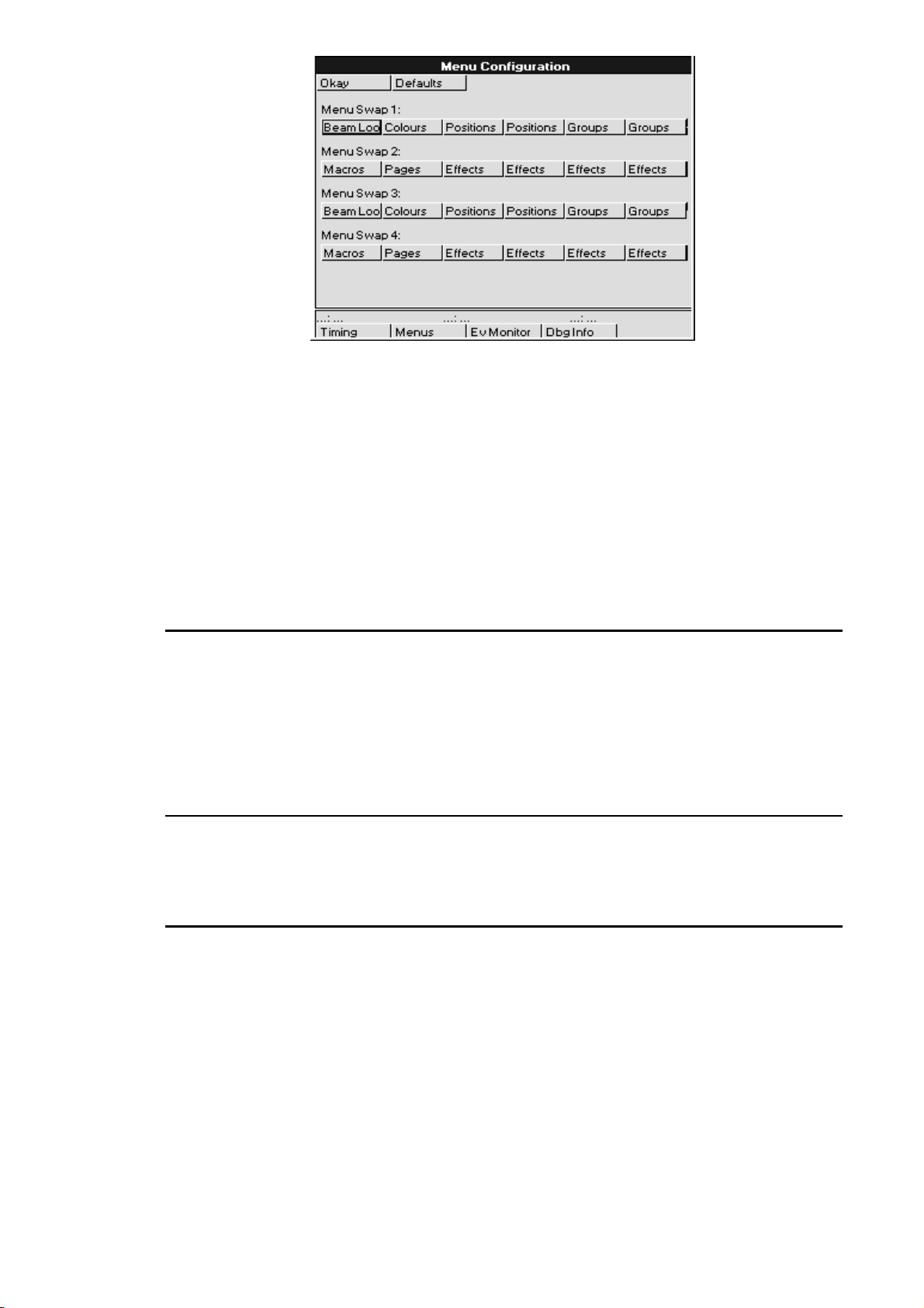
To change the default settings used for menu palettes:
1
From the Control Panel Window, press
bottom toolbar to open the Menu Configuration window.
2
Use the cursor keys and
change.
3
Use the cursor keys and
palette type from the drop down pick box.
4
Repeat steps 2 and 3 until menu s are set u p as desired.
5
Press
when finished.
Okay
to select the palettes to
Set
ENTER
to select the desired
Menus
on the
To reset the palette menus back to normal, pr ess
Defaults
in the Menu Configuration Window.
Event Monitor
The Event Monitor is used to troubleshoot the console. It is accessed from the Control Panel Window by
pressing
moving a fader, parameter wheel or the mou se trackball will display information o n the LCD. To exit you
hold down the
If you suspect that a fader or button is not working on the console, you can use the event monitor to
accurately determine what works and what doesn’t by looking at the information shown on the main LCD.
Ev Monitor
PIG
on the bottom toolbar. Pressing a button on the console or external keyboard,
key and press
ENTER
to exit the event monitor.
Debug Information
This function is for Software Development purposes and will not generally be used. It is accessed by
pressing Dbg Info in the Control Panel Window. The only time when you may need to use it is if instructed
to do so by a technician when trying to find and solve console problems over the phone.
Updating Software
Although future software versions will be loaded from the Control Panel, for the time being it must be done
differently.
The quickest way to upgrade your HOG is through the Internet; to access the Jands page on the World
Wide Web, use http://www.jands.com.au. Select the Download page, then choose HOG & Hog Software
and go to Operating System Software. Transfer the two new files to a pair of IBM-formatted floppy
diskettes (if you choose the zipped versions, you’ll need to unzip it first). The file JNT2.BIN goes on the
first disk, the file JNT2B.BIN goes on disk 2.
Loading these upgrades into the console is simple:
82 •••• HOG – Version 3.20
Page 89

Insert the first disk into the disk driv e.
1
Hold down the
2
Turn on the console power.
3
When the menu appears on the screen, press
4
SW
.
The first disk will load into the console. The co nsole will
5
then ask for the second disk. Change disks and press
ENTER
When the console is finished it will go to the main startu p
6
screen.
ENTER
to continue.
key on the keypad
2, Reload
It is inadvisable to load new software in the middle of a show’s run. In general, if you have
a show that works and don’t need any of the new software’s features, then leave things as
they are. Even though we go to great lengths to test new software, a bug might get
accidentally introduced.
Memory Control
Before performing an operation, the console checks to see if it has enough memory. If memory is running
low, it will give an alert saying
memory to save your show—in this situation, you will have to delete items until you have enough memory.
In low memory situations, playback may also get disabled. User alerts will tell you when this has happened.
Again, to restore playback, delete unessential programming.
Not enough memory
. In some instances, you may not have enough
To help prevent low memory situations, a memory counter in the control panel shows the total memory left.
Also shown is the corresponding number of full cues you can program. Note: a full cue is a cue with all
channels programmed—much larger than a typical cue—so the full cue number will always understate the
number of cues left.
Custom Options
An options text file called "\setup\moreopts.txt" is now saved as part of the show. Edit it to change the
more esoteric console options. Current options supported are:
version = 28 the format version of this file (don’t change this).
MIDI_step_back = 0 set to 1 to enable MIDI output from cue comments on
stepping back (default = 0).
ignore_same_page = 0 set to 1 to prevent a page reload if you change to the
page that you are already on (default = 0).
release_needs_choose = 0 Set to 1 only allows Release to work in combination with
Choose or Pig. Set to 0 allows Release to work as normal,
on its own or in conjunction with Choose or Pig (default
= 0).
delay_before_repeat = 20 Value in hundredth of a second. If you hold down the
cursor and scroll keys, the keys will now repeat after
the amount of time specified here (default = 20).
repeat_interval = 5 Value in hundredth of a second. The repeat interval
between automatic key repeats when holding down a cursor
or scroll key (default = 5).
Postpone_htp_assert = 0 Set to 1 to enable an incoming HTP master to only assert
itself on a page change if:
* The outgoing master was also an asserted HTP master,
* The slider is pulled to 0 and then moved up again,
* Go is pressed
For example, this would be used to stop a master
unexpectedly jumping to full, if the fader is up and you
change pages from an LTP cuelist to an HTP one.
If the option is off or not specified, an incoming HTP
master will automatically assert itself.
This option affects the behaviour of all masters, and
cannot be set on a master by master basis.
Customising the Console •••• 83
Page 90

This Page intentionally Left Blank
84 •••• HOG – Version 3.20
Page 91

Advanced Patch Functions
This chapter covers patch window functions – such as fixture renumbering, paths, etc – not covered in the
Getting Started Chapter.
Different Patch Views
In addition to the first DMX address for each fixture, there are two other views that show patch
information. Pressing View opens a window with 3 options:
default window shown above is the Outputs view. Select a type of view in the drop down menu to change
the display to another output view.
Fixtures, Outputs
, and
Channels
. The
The Fixtures view lists all of the fixtures selected on the console along with their alignment and patch
location(s). For example, the “
output 1. This information is useful when a fixture is patched to multiple locations.
The channels view shows the patch location for every parameter of every fixture.
[1] 400
” shown for VL6 #1 indicates that it is patched to address 400 on
Fixture Editing Spreadsheet
This allows you to edit a fixture’s user number, default and highlight value, colour and gobo names,
intensity profile and tilt offset directly from this window.
Opening the spreadsheet will display all fixtures belonging to the currently active type. You can use the
Group
intensity profile, tilt offset (if relevant) and all slotted pa rameters which have labels that m ay be edited (eg,
gobo and colour wheels). You may select a range of cells by holding
the endpoint of the range. Alternatively, selecting the All row selects all the fixtures of the current type.
button to move through each type in the schedule. Columns are displayed relating to user number,
and cursoring down or clicking
Pig
Advanced Patch Functions•••• 85
Page 92
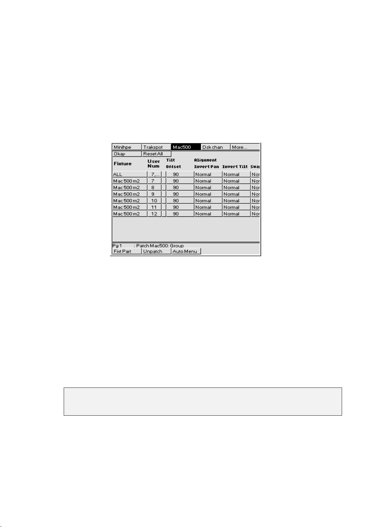
Renumbering Fixtures
It is possible to renumber fixtures in order to access them easier. By default fixture numbers start with 1 for
each type of fixture. Renumbering allows fixtures to be numbered continuously across types. For example,
Cyberlight unit numbers could start at 26. Renumbering eliminates the necessity of having to select fixture
types.
Custom numbers do not have to be continuous. For example Cyberlights could be numbered 1 through 4,
10 and 20. More about Fixture Editing will be explained in later Chapters.
To Renumber the fixtures:
From the patch window, press
1
change to the Edit Fixtures window.
Press the
2
fixture type that you wish to renumber. If the fixture type is not
visible, press
Use the cursor keys to select the User Num box corresponding to
3
the fixture you wish to renumber. To consecutively number all of
one type of fixture, select the box on the
Group
button and then use the toolbar to select the
More…
Edit Fix
on the toolbar to
line.
ALL
Press
4
changing all of the fixtures. Note: You cannot give the same
number to multiple fixtures of the sam e type.
Repeat steps 2 through 4 until you have renumberd all the fixtures
5
to suit your show.
Press
6
If a range is selected, subsequent cells are assigned consecutive values. Numbers are always shuffled so as
to be assigned to fixtures in numerical order. Two fixtures of the same type may not share the same user
number. An asterisk next to a number indicates it is shared by fixtures of another type.
Once you have set up your user numbering, you can use them to patch, but remember you
will still need to use Group and Fixt Part to access different patch parameters of a multiple
patching fixture such as a VL5.
Fixture Alignment
Occasionally it’s necessary to hang a moving light upside down or sideways. To have all of the fixtures
moving in the same direction regardless of how they’re hung, use the fixture alignment features in the
Fixture Editing Spreadsheet.
To change an alignment:
and enter the fixture number or the starting number if
Set
to return to the Patch Window.
Okay
86 •••• HOG – Version 3.20
Page 93
1
Open the Fixture Editing Spreadsheet. This is found in
the Patch Window. To open the Fixture Editing
Spreadsheet from the Main display, press
Patch, Edit Fix
2
Use the
of fixture for which you wish to change the alignment.
3
Use the cursor keys to move around the Fixture Editing
Spreadsheet. Select a group of fixtures by holding down
the
select all the fixtures of that type, use the ALL row.
4
Press the
and Invert/Swap.
5
Press
Invert Pan
normal, and should be used for fixtures hung in reverse orientation to the others.
pan and tilt parameters for sideways-hung fixtures.
Range Labels
Press
heading.
Note that auto menus incorporate any changes made in the fixture spreadsheet, so that if
range labels are swapped or changed, the palettes will reference the new ranges
(automenus must however be regenerated to take account of any subsequent
modifications).
and type in a label for the range. Ranges which do not appear in automenus have a ‘#’ next to the
Set
Group
key and using the up and down cursor keys. To
PIG
Set
when you’re done.
Okay
and
Invert Tilt
.
button and the toolbar to select the type
key to toggle the selection between Normal
make the pan and tilt parameters respond in a reverse manner to
Setup
,
Swap Axes
swaps the
Advanced Patch Functions•••• 87
Page 94

This Page intentionally Left Blank
88 •••• HOG – Version 3.20
Page 95
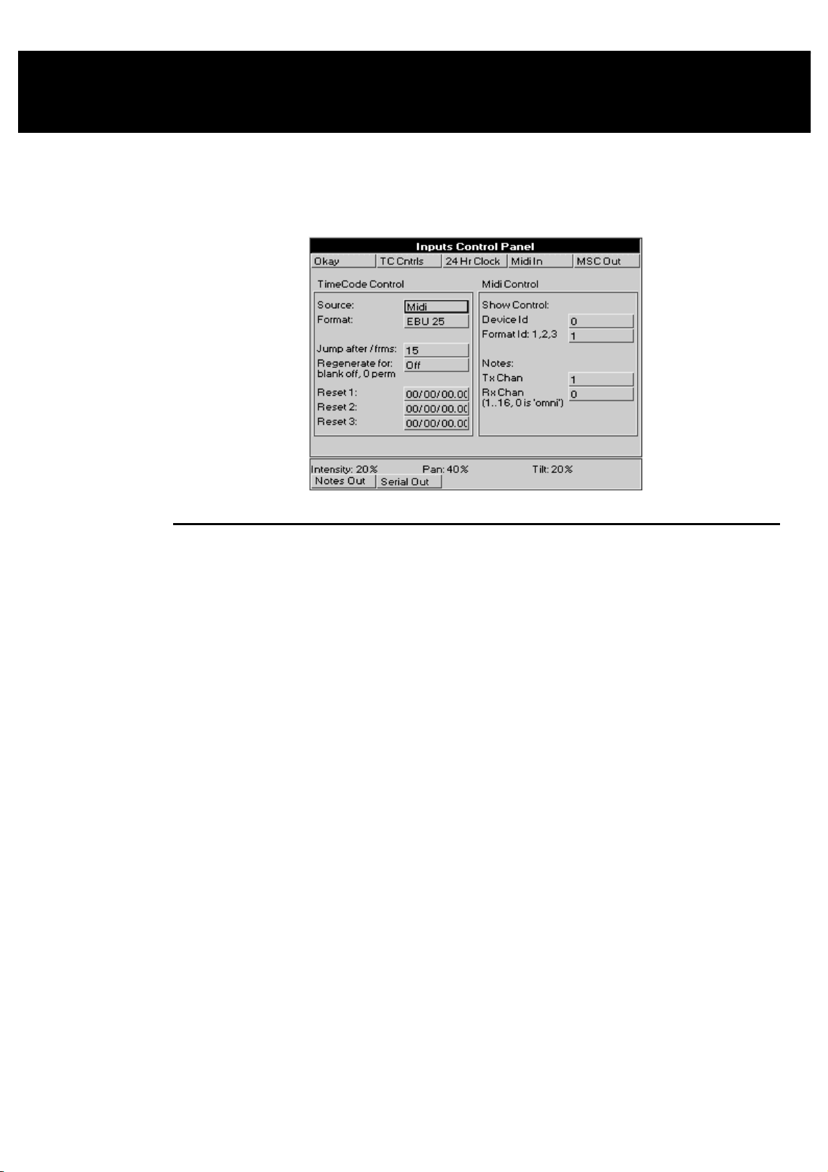
Console Inputs
This chapter covers the use of MIDI, and Timecode inputs. These features are accessed through the Inputs
Control Panel window
To open the Inputs Control Panel window, press
setup
and
Inputs
.
MIDI Timecode
The HOG can only receive MIDI Timecode. It has programmable error correcting features. The console
can also simulate Timecode to help with programming when the Timecode source is not ready.
Setting up the console to read Timecode
Before using Timecode, the console must be configured to accept Timecode:
Press
1
Press
2
input.
Connect the MIDI signal to the MIDI Input.
3
Move the selection box to
4
cursor keys and
within the drop down menu..
Move the selection box to
5
cursor keys and
EBU 25, NTSC 30
menu.
Press
6
control panel at the bottom of the screen (this panel will remain
open until you close it by pressing the
toolbar).
Press
7
timecode from the MIDI in port. Pressing
time will turn this off again.
Timecode Error Correction
Entering a time in the
signal drop out. This will continue for the amount of time selected in the
enter 0, regeneration will be continuous. To turn automatic timecode regeneration off, set the value in the
Regenerate for:
.
Setup
Inputs
TC Cntrls
Tcode On
to bring up the options window for Timecode
Source:
to choose either
Enter
Format:
to choose the type of input:
Enter
and
SMPTE 30
on the top toolbar to open up the timecode
to allow the console to simulate or read
Regenerate for:
box to a blank with the backspace button.
and press
Midi
and press
, from within the drop down
Okay
turns on automatic generation of Timecode should the
box
. Now use the
Set
or
Simulate
. Now use the
Set
button on the bottom
Tcode On
from
Film 24
a second
Regenerate For:
,
box. If you
Console Inputs •••• 89
Page 96

Bad Timecode tapes will have drop outs that look to the console like Timecode jumps. Increase the value in
Jump after /frms:
the
(the default value is 15 frames).
Programming Timecode into Cuelists
Timecode functionality is built into the norm al cue list timing structure (wait), making it very easy to run
programmed cues to Timecode. Any cue list active on a master on the console can receive Timecode.
To setup a cuelist to use Timecode, program the cuelist as normal, but instead of using normal cue wait
times, use Timecode frame numbers:
Select a cue wait box.
1
entry box to reduce the sensitivity of the console to jumps in Timecode signal
Press
2
Enter a Timecode number in the form hh/mm/ss.ff, eg, 1/0/10.02,
3
or 0/0.5 You need to use at least one slash / for the console to
interpret it as a Timecode value.
Press
4
Blank First Cue
the cuelist from wrapping around at the end.
You don’t have to use Timecode frames for the waits of all the cues. You can mix them with normal wait
times, follows and halts. This is useful to avoid having to synchronize every cue to frame times. Instead, the
first cue can be synchronized, and then subsequent cues set with normal wait times relative to the first.
Loops can be triggered with Timecode,
Instead of entering numbers by hand, it’s possible to use the
current cuelist window) to enter them automatically, editing manually later for fine tuning. Simply turn on
the function and press the Go button to signal when cues are meant to execute. Only cues set to Halt (Wait
is blank) will receive values.
Playing back with Timecode
To playback cuelists under Timecode control.
Select Timecode
1
Press
2
Press
3
toolbar) .
.
Set
ENTER
TC Cntrls
Tcode On
. The console automatically turns on the
Source
option when you use Timecode, to prevent
but do NOT put Timecode inside a loop
Learn Timing
as
.
on the Timecode control panel (bottom
Midi
.
Add
.
function (found in the
Start the tape running.
4
Press Go on the playback master. This is needed since the operator
5
still has overall manual control.
Cues will now be triggered by Timecode.
Rewinding
There is no need to do anything to the master when rewinding the tape. When you start playing Timecode
again, all active masters will reposition their cuelists to the correct position in the cuelist.
Simulating Timecode
If you don’t have a Timecode source available, you can simulate Timecode in order to test /run your show.
From within the Input Panel Window, select the Timecode Source as
Control panel by pressing
stop the Timecode, press
To reset the Timecode to one of three preset Reset values, press either
on the Timecode control panel (lower toolbar).
To change the Timecode start frame, use the cursor keys and the keypad to alter the respective
value. If Timecode was not running, start it by pressing
Cues will now be triggered by Timecode.
TC Cntrls
TCode On
, and press
again.
TCode On
TCode On
. This will start simulating Timecode. To
Simulate
Reset 1, Reset 2
.
. Open the Timecode
or
Reset 3
Reset
:
90 •••• HOG – Version 3.20
Page 97

MIDI
MIDI Receive
The console can receive:
MIDI note data, such as from a MIDI keyboard, another HOG or a Whole Hog II.
•
MIDI show control (MSC) messages, such as from a show control sequencer, or another console with
•
MSC support.
MIDI Timecode, such as from a Timecode converter box.
•
Any or all of these kinds of messages can be received simultaneously.
To turn on MIDI reception, press
MIDI Transmit
The HOG can transmit:
MIDI note data (to send to a slave backup console, for instance). Press
•
MIDI show control messages (to trigger other show control equipment). Press
•
MIDI Notes
To trigger the console from a piece of MIDI equipment
Select
MIDI In
which channel is being used under
that it responds to all channels).
To trigger other MIDI equipment using the console
Select
Notes Out
equipment under
To setup another console as a tracking backup
Slave together two consoles as follows:
1
from the Input Panel, and make sure that the console and the MIDI equipment agree on
from the Input Panel, and set the MIDI channel to the correct channel for the receiving
Tx chan
To make sure both start from the same point, reset both
consoles and load the
MIDI In
Rx chan
.
identical
(found in the Input Panel window).
(setting the console to channel 0 puts it in ‘omni’ mode, so
show onto both machines.
Notes Out
MSC Out
to turn on.
to turn on.
Open the Input Panel on both, and make sure that the two
2
consoles agree on which MIDI channel is being used.
Select
3
4
Changing the Note messages
If your MIDI equipment does not use the same messages as the standard HOG setup, you can rearrange
which note messages get sent on which button press, fader move or wheel move.
By default, all console actions are mimicked using low MIDI note numbers and MIDI controllers. The
MIDI mapping information is held in the file “setup\MIDImap.txt” on the show disk and you can edit this
file on a PC.
Notes Out
console.
Select
MIDI In
the master console fully.
from the Input Panel on the master
on the slave console. It will n ow track
Console Inputs •••• 91
Page 98

Here is the default MIDImap.txt file from an HOG show disk:
version = 40
; NB: MIDI Note & Controller numbers range from 1 to 128
group_menu = note:1
position_menu = note:2
colour_menu = note:3
beam_menu = note:4
macro_menu = note:5
page_menu = note:6
choose = note:7
go = note:8
halt = note:9
flash = note:10
fader = note:11
lh_tool = note:12
rh_tool = note:13
keypad = note:14
wheel = note:15
touchpanel = note:16
others = note:17
coord_x = controller:1
coord_y = controller:2
fader_val = controller:65
wheel_val = controller:66
flash:8 = note:47
ext_keys = note:18
func_keys = note:19
Example: “go = note:8”
This means that all go keys are transmitted as MIDI note # 8 .
The note velocity is used to indicate which of the go buttons are being transmitted; eg, if fader 3’s
go
button is pressed, a ‘note on’ event for note #8 with a velocity of 3 is transmitted. When th e key is released ,
a ‘note off’ event for note #8, velocity 3 is transmitted.
If you wanted to send a particular go button over a unique note (and not use velocity to differentiate
buttons) then you could add the line ‘go:3 = note:50’. In this case a ‘note on’ for note #50, velocity = 63
will be sent when the key is pressed, and a ‘note off’ for note #50, velocity = 0 will be sent when it is
released. All other go keys will use the prior mapping, ie. via note # 8 .
92 •••• HOG – Version 3.20
Page 99

MIDI Map File Format
The console events that can generate MIDI and their map file name are listed below:
Whole Hog II HOG JandsHog Map file name
Choose buttons Choose buttons Select Buttons choose
Go buttons Go buttons Go buttons go
Halt buttons Halt buttons Halt buttons halt
Flash buttons Flash buttons Flash buttons flash
Faders Faders Faders fader (preceded by
value sent by
fader_val)
Tool buttons above
right hand lcd
Numeric keypad Numeric keypad Numeric keypad keypad
Parameter wheels Parameter wheels Parameter wheels wheel (preceded by
Next page button next_page
DBO button dbo
Release button release
Step up skip_up
Step down skip_down
Main stop main_stop
Main go main_go
Tool buttons above
left hand lcd
Touchpanels pressed touchpanel (preceded
All other buttons All other buttons others
Tool buttons Tool buttons rh_tool
value sent by
wheel_val)
lh_tool
by X and Y coords
sent by coord_x,
coord_y)
Fourth Menu Palette Group menu buttons group_menu (for all
menus, index 21 & 22
are the scrollup &
down keys)
Third Menu Palette Position menu
buttons
Second Menu Palette Colour menu buttons colour_menu
First Menu Palette Beam menu buttons beam_menu
Macro menu buttons macro_menu
Page menu buttons page_menu
position_menu
The following are
used to encode
continuous values,
and precede other
messages as listed
above:
coord_x
coord_y
fader_val
wheel_val
The possible MIDI messages that you can map to are:
Map file name Index Console event s which can be mapped to
the MIDI event
note note number, eg, ‘note:34’ All button events
polyatouch note number, eg,
‘polyatouch:34’
controller controller number, ie, 1 > 32
[14 bit] & 65>128 [7 bit]
progchange program number All button events
pitchwheel none Value events
chanatouch none Value events
All button events
Value events
Console Inputs •••• 93
Page 100

Controllers 33 to 64 are the LSB parts of controllers 1 to 32, so are unavailable.
Console button events can only map to MIDI notes, polyphonic aftertouch and program change (note that
faders are also button events as they refer to which fader was used; the actual values are sent separately).
Continuous values (like a fader position) can only be sent via a controller, pitch wheel or channel
aftertouch. In addition, coord_x & coord_y must be mapped to a 14 bit controller, ie, controller 1 to 32 or
pitchwheel.
All console numbering starts at 1 rather than 0, eg, use fader 1, not fader 0.
When several buttons are mapped to one note (eg, choose = note:7) then the velocity data of the note is
used to index the actual choose button being pressed.
Some keys cause events to occur when they are released as well as when they’re pressed - if a single key is
mapped to a note then the console will respond to either a note off or a zero velocity to release the key. If a
key that needs a release message is mapped to a non-releasable MIDI event (like program change) then a
warning will occur when the show disk is load ed.
Others
Set others:1 Time others:35
Setup others:2 Blind others:36
Slash others:3 Try cue others:37
Dec others:4 Pig others:44
Minus others:5 Next page others:45
Plus others:6 DBO others:46
Thru others:7 Release others:47
At others:8 Skip up others:48
Full others:9 Skip down others:49
Backspace others:10 Cursor up others:53
Enter others:11 Cursor down others:54
Group others:12 Cursor left others:55
Position others:13 Cursor right others:56
Colour others:14 Begin others:57
Beam others:15 End others:58
Active others:17 Page up others:59
Next others:20 Page down others:60
Copy others:21 Page left others:61
Move others:22 Page right others:62
Delete others:23 Effect others:63
Undo others:24 Menus others:65
Clear others:25 Monitor others:66
Load others:26
Update others:27 Whole Hog II Specific
Record others:28 Main stop others:50
Macro others:29 Main go others:51
Page others:30 Activate others:52
Cue others:31
List others:32
Highlight others:33
Goto others:34
For example, to map the Record key to middle C then the midimap.txt entry would be
note:72
.
others:28 =
MIDI Serial Output
Custom MIDI messages can now be output using a cue’s comment box. You can use this to trigger
equipment that cannot receive MIDI Notes or MIDI Show Control.
To use MIDI Serial Output:
94 •••• HOG – Version 3.20
 Loading...