

Page 1
)3
Page 2

Contents ii
Revision 01 – 3 June 1999 FP12 DIMMER USER MANUAL
EMC COMPLIANCE
This product is approved for use in Europe and Australia/New Zealand and conforms to the following
standards:
European Norms Australian / New Zealand
Standards
EN 55014-1 AS/NZS 1044
EN 55014-2 AS/NZS 4251.1
EN 60335-1 AS/NZS 3350.1
To ensure continued compliance with EMC Directive 89/336 and the Australian
Radiocommunications Act 1992, use only high quality data cables with continuous shield, and
connectors wit h cond u ctive backshell s. Exa mples of such cables are:
DMX: Belden 8102 100% Aluminium foil screen, 65% Copper bra i d.
JANDS ELECTRONICS PTY LTD 1999
All rights reserved
DISCLAIMER
Information contained in this manual is subject to change without notice and does not
repre sent a c ommitment on the par t of th e vend or. JAND S EL EC TR ON IC S PTY LTD
shall not be liable for any loss or damage whatsoever arising from the use of
information or any error contained in this manual.
It is recommended that all service and repairs on this product be carried out by JANDS
ELECTRONICS PT Y LT D or its author ised service agents.
JANDS ELECTRONICS PTY LT D cannot accept any liability w ha ts oe v e r for a ny los s
or damage caused by service, maintenance or repair by unauthorised personnel, or by
use other t han that intended by the manufacturer.
JAN DS FP Ser ies dimme rs mus t o nly be u sed for the p ur pos e t hey we re int end ed b y
the manufacturer and in conjunction with this operating manual.
Disconnect mains power when not in use.
Manufactured in Australia by:
JANDS ELECTRONICS PTY LTD ACN 001 187 837
40 Kent Rd
Locked Bag 15
Mascot NSW 2020
Australia
PHONE: +61-2-9582-0909
FAX: +61-2-9582-0999
INTERNET: www.jands.com.au
Page 3

Contents ii
Revision 0.1 – 3 June 1999 FP12 DIMMER USER MANUAL
Table of Contents
1.0 Introduction
2.0 Equipment Description
2.1 Front panel layout ...............................................................................................2-1
3.0 Getting Started
3.1 Connecting power............................................................................................... 3-1
3.2 Setting the mains frequency................................................................................. 3-1
3.3 Powering up........................................................................................................3-2
3.4 Connecting loads.................................................................................................3-2
3.5 Connecting DMX-512 input................................................................................ 3-2
3.6 DMX Termination...............................................................................................3-2
3.7 Power-up sequence.............................................................................................3-2
4.0 Dimmer Operation
4.1 Operating modes................................................................................................. 4-1
4.1.1 DMX mode...........................................................................................4-1
4.1.2 Test mode............................................................................................. 4-1
4.2 Status LED......................................................................................................... 4-3
5.0 Fault Diagnosis
5.1 Output protection................................................................................................5-1
5.2 DMX faults ......................................................................................................... 5-1
5.3 Phase fault indication...........................................................................................5-2
5.4 Thermal protection.............................................................................................. 5-2
5.5 Over-voltage...................................................................................................... 5-2
5.6 Fault finding guide.............................................................................................. 5-3
6.0 Installation
6.1 Dimmer Vent ilation............................................................................................. 6-1
Page 4

Contents iii
Revision 0.1 – 3 June 1999 FP12 DIMMER USER MANUAL
7.0 Maintenance
8.0 Technical Data and Specifications
8.1 DMX connector pin-outs .................................................................................... 8-2
8.2 DMX bank allocations.........................................................................................8-2
8.3 Mains wiring colour codes...................................................................................8-3
8.4 Internal Mains Wiring..........................................................................................8-3
8.4.1 Normal Three Phase plus Neutral Operation..........................................8-3
8.4.2 Single Phase Operation ......................................................................... 8-3
8.4.3 Delta Supply Operation......................................................................... 8-3
Page 5

Introduction 1-1
Revision 0.1 – 3 June 1999 FP12 DIMMER USER MANUAL
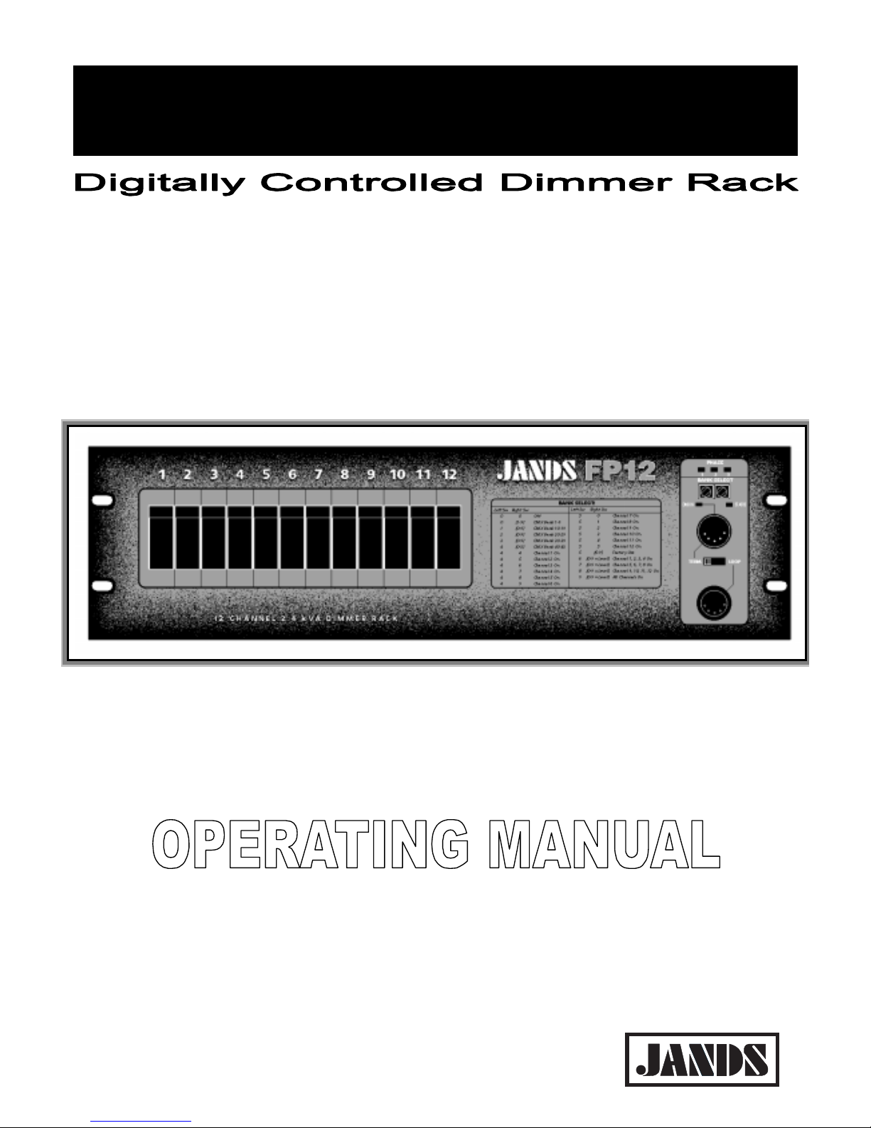
1.0 Introduction
The JANDS FP12 is a high quality, rugged, 12 channel, 2.4kVA per channel (10A/240V)
dimmer ra ck specifically de signed fo r demand ing tou ring and thea tre ap plications.
The FP12 can be powered from three-phase or single-phase mains supplies. The FP12
features opto-controlled Triacs and medium risetime chokes protected by
thermal/magnetic circuit breakers. The FP12 uses microprocessor-based digital control
for accurate dimming a nd in -built tes t funct ion s. Dig ital control is v ia stand ard DMX-51 2
protocol.
The FP12 features toroidal output chokes. These chokes provide excellent high
frequency noise suppression and, together with the temperature-controlled fan, low
acoustic noise.
Co n tr ol s ig n a l to the dimme r is v ia a s ta nd ar d D M X -512 socket at t he front panel, while
t h e d immed outlets an d three phase power entry are located on th e r ea r panel.
Feat u re s
• 12 x 2.4 KW dimming channels
• DMX-512 digital control protocol
• DMX terminating swit ch
• Su itable for both tourin g a nd permanen t in stallatio n s
• Soft turn o n characteristic
• Low acoustic/electrical noise
• Toroidal output chok es
• Circuit breaker protection of output devices
• Three mains phase indicator LEDs
• Built in test facilities
• Dimmer c urve set for linear r elationship between the con trol input and output power
• Compensates for fluctuations in the mains supply voltage, and filters superimposed
mains con trol tone s, ens uring a c on stan t light ou tpu t and inc re ased lamp life
• Rack mounted (3 rack units)
• Microprocesso r control
• Temperature-controlled cooling fan
• Temperature monitor and thermal cut-ou t
• Dimmer will hold last DMX value sh ould control data b e inte rrupted
• 50/60Hz operation
• CE and C-Tick approved
Page 6
Equipment Description 2-1
Revision 0.1 – 3 June 1999 FP12 DIMMER USER MANUAL
2.0 Equipment Description
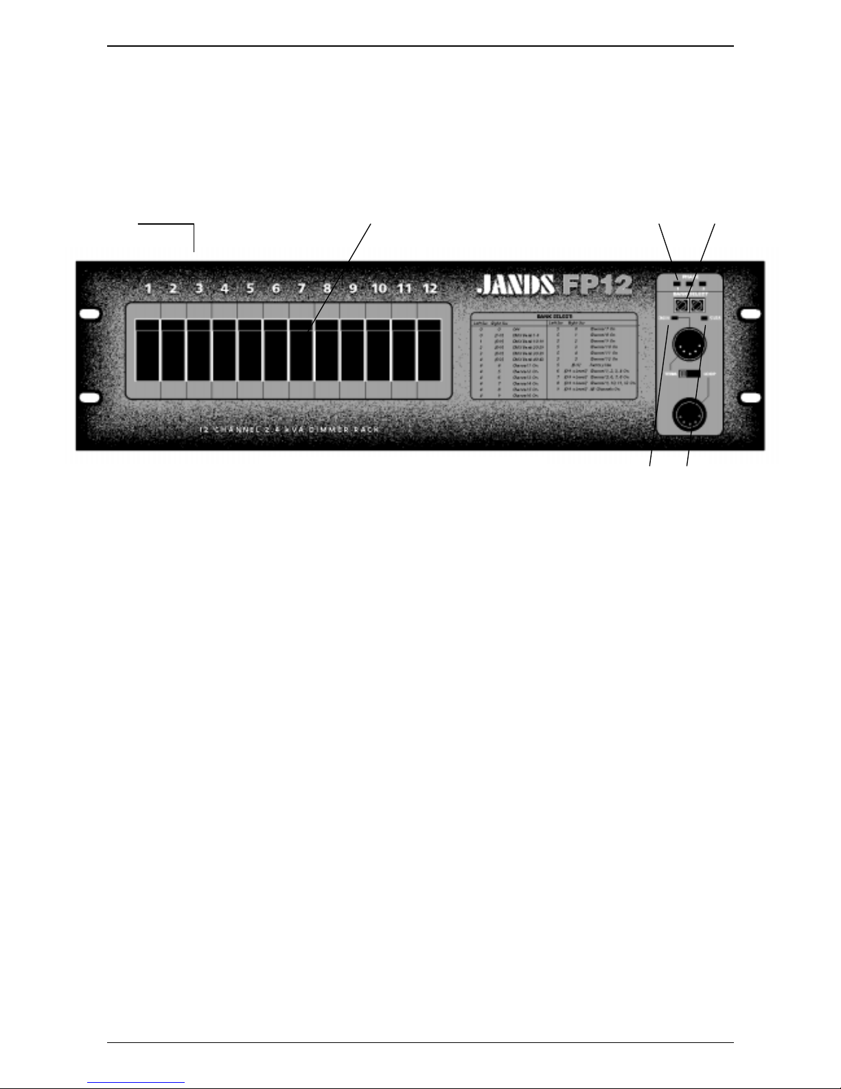
2.1 Front panel layout
Refer to Fig 2.1 (below) for a description of the front panel controls.
1. Channel output sockets (rear panel): The twelve output sockets are each rat ed at
10 amps.
2. Channel circuit breakers: If a breaker trips during use ensure the fault has been
cleared before resetting.
3. Bank select switches: These switches select the DMX start bank and the Test
functions.
4. DMX IN LED: A red LED indicates the presence of DMX signals. If there is no
DM X s ig na l, t he LE D w ill fla sh a t a r a t e of a p p r o xima t e ly 2 s e co n d s o n - 2 s ec o nd s
off.
5. STATUS LED: A red LED flashes in the presence of a fault. In normal operation
this L ED shou ld be o ff.
6. PHASE LEDs: Three blue LEDs (one for each phase) indicate that t he three phase
mains supply is available.
➀ ➁ ➂
➃ ➄
➅
Figure 2.1FP12 front panel layout
Page 7

Getting Started 3-1
Revision 0.1 – 3 June 1999 FP12 DIMMER USER MANUAL
3.0 Getting Started
The FP12 would normally be rack mounted before any wiring is terminated. Refer to
se ction 6 .0 Installatio n fo r installat ion de tails.
3.1 Connecting power
Th e FP 1 2 d immer is s up plie d w ith a fle xible cab le fit t ed wit h a mu lt ipin po w er plu g fo r
the connection of incoming mains power. The FP12 is ideally powered from a three
phase star (four wire plus earth) supply. If the dimmer pow e r ca b le is d ama g e d it mu s t b e
replaced with another cable available from JANDS or its service agents.
The upstream supply must be protect ed by fuses or circuit breakers at not more than the
rated max imum.
The power plug should be connected to an appropriately rated socket o utlet. The plug’s
retaining lock ring (if pres ent) must be screwe d home .
WARNING
DAMAGE TO THE PLUG MAY OCCUR IF THE RETAINING LOCK RING IS
NOT PROPERLY SECURED.
Ensure adequate mains plug access once the dimmer is insta lled .
3.2 Setting the mains frequency
The FP12 can be configured to run from either 50Hz or 60Hz mains power. As supplied
from the facto ry the dimmer is con figu re d for 50 Hz.
Th e dimmer o perat ing frequ ency may be c h anged as follo ws:
• Disconnect the mains supply to the dimmer
• Remov e the lid
• Change the three jumpers on the main circuit card as shown in Figure 3.4
• Replace the lid and reconnect power
Figure 3.4: 60Hz jumper locations
60
50
50
60
50
60
Page 8

Getting Started 3-2
Revision 0.1 – 3 June 1999 FP12 DIMMER USER MANUAL
3.3 Powering up
Turn on the power and check that the three PHASE indicator LEDs are on before
connecting any loads. If any of the PHASE LEDs are dim or off, power down and
remedy the fault before trying again. Refer to section 5.3 Phase fault indication.
If all is well, po we r do wn and connec t loads.
3.4 Connecting loads
The standard output connector s are twelve Clipsal 415P 10 amp sockets (export models
may differ from these configurations). Ensure any plugs are pushed firmly into their
sockets.
The FP12 will drive most incandescent loads as well as pinspot s, fans, and dimmable
fluorescent tub es. The load shou ld be within t he s pe cified limits.
3.5 Connecting DMX-512 input
The input signal to the dimmer should conform to the USITT DMX-512 1990
specification. The DMX input connects t o the frontpanel socket labelled “DMX IN”. T he
DMX signal may be daisy-chained to the next dimmer via the connector labelled
“LOOP”.
The red DMX IN LED indicates the presence of DMX signals.
The DMX receiver input is protected against extreme over-voltages across any input pins
and from any input to chassis. The “terminating” resistor is not pro tected against o vervoltages.
3.6 DMX Termination
In any DMX-512 system the signal should be terminated at the last d imme r or receiver in
the chain, and the FP12 can provide this function. To terminate the DMX signal, set the
frontpanel slide switch from “Loop” t o t he “Term” position. Not e that in this position no
signal is present at the “Loop” connecto r.
3.7 Power-up sequence
When powering up lighting systems, the following sequence should be used:
1. First the control desk;
2. Then any softpatches and/or DMX r eceivers;
3. Finally th e dimmers, prefera b ly on e a t a time starting fro m the first dimmer rack in th e
DMX loop.
This pro ced ure min imises t he ris k of la mps and fixt ures re spondin g to any fals e DMX
da ta p ro du c e d b y c ontrol d e s k s or a n c illa ry e qu ip me n t a t tu r n -o n ( p rod u c in g the lig h ting
equivalent of an audio “thump”) and prevents damage to lamps, dimmers, and other
contro lled devices.
Use the reverse procedure when powering down.
Disconnect mains power when not in use.
Page 9

Dimmer Operation 4-1
Revision 0.1 – 3 June 1999 FP12 DIMMER USER MANUAL
4.0 Dimmer Operation
Th is s e c tion a s s u mes th e d imme r ha s b e e n c or re c tly co n nec te d to thre e p h a s e po we r a n d
a source of DMX-512 control signal.
4.1 Operating modes
The FP12 has two operat ing modes:
1. DMX mode: the dimmer is controlled from an external DMX-512 control
console,
2. Test mode: the d immer is con trolle d by the intern al mic rop roc essor.
4.1.1 DMX mode
In this mode, the DMX Bank Select switches are used to select which bank of 12
channels from the 43 possible DMX-512 banks will con trol the FP12 .
See Table 4.1 (below) for a list of banks and their corresponding Channels.
Decide which bank of channels is required, and rotate the selector switches to the
desired setting. For example, if DMX Channels 25 to 36 are desired (ie. bank 3), set
selectors to “03”. FP12 Channel #1 is now DMX Channel #25. A FP12 with this
setting ignores DMX Channels 1 to 24 and 37 to 512, and only decodes Channels 25 to
36 as it ’s dimmer information.
Set tin g the Selectors to “ 00 ” p uts the d immer in a st andby state, w ith all channels o ff.
Bank Channels Bank Channels Bank Channels Bank Channels
00
Outputs Off
11 121 - 132 22 253 - 264 33 385 – 396
01 1 - 12 12 133 - 144 23 265 - 276 34 397 – 408
02 13 - 24 13 145 - 156 24 277 - 288 35 409 – 420
03 25 - 36 14 157 - 168 25 289 - 300 36 421 – 432
04 37 - 48 15 169 - 180 26 301 - 312 37 433 – 444
05 49 - 60 16 181 - 192 27 313 - 324 38 445 – 456
06 61 - 72 17 193 - 204 28 325 - 336 39 457 – 468
07 73 - 84 18 205 - 216 29 337 - 348 40 469 – 480
08 85 - 96 19 217 - 228 30 349 - 360 41 481 – 492
09 97 - 108 20 229 - 240 31 361 - 372 42 493 – 504
10 109 – 120 21 241 - 252 32 373 - 384 43 505 – 512
Table 4 .1 DMX ba nk / Cha nne l allocat ion
4.1.2 Test mode
In th is mo de , th e F P1 2’ s int e rna l co n tr o ller is u se d t o d riv e t he dimme r ch ann els . I t is
accessed by setting the Selector switches to banks between “44” and “99”. No DMX
contro l is necessary, but a control signal may be left connected if desired.
Page 10

Dimmer Operation 4-2
Revision 0.1 – 3 June 1999 FP12 DIMMER USER MANUAL
Th is mod e is s p lit into tw o s e c tions wit h in d ividu a l C h a nn e l te s ting fro m b a nks “ 4 4 ” to
“59” and group channel testing from banks “60” to “99”. The first section is not level
contro llable and each channel is driven to full.
Refer to Table 4.2.
Selector Channel Output
Switches Under Test Level
44 Channel 1 Full
45 Channel 2 Full
46 Channel 3 Full
47 Channel 4 Full
48 Channel 5 Full
49 Channel 6 Full
50 Channel 7 Full
51 Channel 8 Full
52 Channel 9 Full
53 Channel 10 Full
54 Channel 11 Full
55 Channel 12 Full
56 - 59 12 Step Chase Full
Table 4.2 TEST MODE – I ndividual Channel Select i on
The se cond section is level cont rollable, t he level being set by the right hand S elector
switch. The left-hand Selector switch changes the grouping. Refer to T able 4.3.
Selector Switches Channel Channel Left
Right Grouping Level
6 0-9 Channels 1-4 ON (Phase A) 0-9
7 0-9 Channels 5-8 ON (Phase B) 0- 9
8 0-9 Channels 9-12 ON (Phase C) 0-9
9 0-9 Channels 1-12 ON 0-9
Table 4.3 TEST MODE – Group Selection
Page 11

Dimmer Operation 4-3
Revision 0.1 – 3 June 1999 FP12 DIMMER USER MANUAL
4.2 Status LED
The Status LE D is used to indicate fault conditions. In normal operation this LED should
not illumin ate. Wh en activ e this LE D will either be flashing or on c on tinuously.
1. When the LED is flashing an over-temperature o r o ver-voltage condition is present,
and the dimmer outputs will be off until the over-voltage or over-temperature
condition is re moved.
2. When the status LED is on continuously, one or more of the following error
conditions have o ccurred :
• Over-voltage
• Over-temperature
• Serial data errors
• Software failure
Th e d immer outputs ar e a ctive while the Sta tus LED is on continuously.
If the Status LED is on it may be cleared by changing the setting of the bank select
sw itche s or by sw itching the dimmer off momentarily.
Page 12

Fault Diagnosis 5-1
Revision 0.1 – 3 June 1999 FP12 DIMMER USER MANUAL
5.0 Fault Diagnosis
NOTE
Contact your authorised JANDS Distributor for repairs or servicing.
In Australia refer all repairs to an authorised JANDS service agent or return the
faulty unit in suitable packaging to:
JANDS ELECTRONICS Service Dept,
40 Kent Rd
Mascot NSW 2020
Australia
5.1 Output protection
Each of the twelve output circuits is prot ected by a 10 amp fast-acting thermal/magnetic
circuit breaker. These break er s are de signed to pass the rated cu rren t, but will disconnect
the output circuit for any overload condition (the larger the overload, the quicker the
disconnect ion).
NOTE: 3-pin GPO outlet sockets are rated at 10 amps. Dimmer channels should
not be loaded beyond th e socket capaci t y.
The breakers protect the dimmer’s output devices from short-circuit loads and faulty
wiring lo oms, and save on expen sive dimmer repair s. A tripped cir cu it b reaker indicates a
load fault th at req uir es immediate attention .
If a short-circuit lamp or output cable is plugged into t he dimmer, th e b r e a ke r w ill trip to
dis c onn e c t the fa u lt fro m th e d imme r. In n e a r ly a ll c irc u ms ta nc es, this is q u ick e n ou g h to
prevent damage to the output devices.
In some circumstances however, a triac failure may be experienced, although these
devices are usually quite reliable and robust. If a triac does fail, it will either turn a
channel on to full (triac short-circuit), or turn it off (triac open-circuit). If a triac fault
should occur, that channel may be isolated by tripping that channel’s circuit breaker.
Th ese br eak ers have be en sp ecified for e lect ric al pr ot ect ion, re liabilit y and s afet y. T hey
will allow r e p ea ted t u rn-o n sur g e s to c old la mp s w ith ou t fa ilu re , w h ile s till p rot ectin g th e
triacs . The br eake rs will inte rrupt larg e sho rt-circuit fault cur re nt s with out damage.
5.2 DMX faults
Th e FP 12 dimme r fe at u re s a n “O ut p ut H o ld” fac ility t ha t “r eme mber s” t he last r eceived
DMX message. In the event of a cable being unplugged or severed, the FP12 dimmer
rack will continue to output the “Held” DMX levels until a new DMX message is
provided.
The DMX IN LED will “flash ” slowly if the DMX signal is remov ed .
Note that control consoles, when powered down, may transmit spurious DMX data
which can unint entionally cau se dimmer channels t o tur n on. Disco nnect mains po wer
when not in use.
The DMX receiver input is protected against extreme over-voltages across any input pins
and from any input to chassis. The “terminating” resistor is not pro tected against o vervoltages.
Page 13

Fault Diagnosis 5-2
Revision 0.1 – 3 June 1999 FP12 DIMMER USER MANUAL
5.3 Phase fault indication
The three blue PHASE LEDs will show when a ll th ree power input phases are present.
WARNING
IF ONE OR MORE PH AS E LEDS IS O FF, IMMEDIATELY DIS CO NNECT
POWER TO THE DIMMER AND CHECK THE M A INS SU PPLIES AND
WIRING BEFORE RE-CONNECTING POWER TO THE DIMMER.
Although t he dimmer will survive most power supply faults, indications of unusual or
po tentially danger ous power c onditions should ne ver be ignored.
5.4 Thermal protection
The FP12 dimmers feature temperature-controlled fan cooling. As the internal
temp er ature of th e d immer increases, the fan speed a lso incre ases.
Th e in t e rn al h e at s ink t e mp er a t u r e is c o ns t a nt ly mo n it o r e d by t he d imme r. I f t he h ea t s ink
temperature rises above the specified maximum, the dimmer will automatically shut
do w n th e o ut p ut dr ive . T he fa n will c o nt inue t o co o l t he h ea ts ink du rin g t he shu t do w n
period.
The electronic shutdown is backed up by a buried cutout , which shuts down power to all
electronics other than the cooling fan should the temperature continue to rise.
Even though the FP12 is a fan-cooled dimmer, it is very important that adequate
ventilation is provided when in use, particularly around the sides of the chassis. If air
circulation to t he air vents is blocked and/or the ambient air temperature is too high, the
dimmer will shut down and the status LED w ill flash un til th e temperat ure is red uced .
Refer to sect ion 6.1 Dimmer Ventilation regarding FP12 ventilation requirements.
5.5 Over-voltage
The FP12 incorporates an over-voltage cutout that constantly monitors the incoming
mains volt age . If t he main s volt ag e rise s abo ve t he s pec ified ma ximum t he dimme r will
shut down and th e status LED will flash until the o ver- vo ltag e con dition is re mov ed .
Page 14

Fault Diagnosis 5-3
Revision 0.1 – 3 June 1999 FP12 DIMMER USER MANUAL
5.6 Fault finding guide
FAULT SYMPTOM POSSIBLE CAUSE REMEDY
Breaker trips wh en desk channel
flashed to full or near full
Larg e inca ndescent load
Excessive load
Use console preheat facility
Reduce channel loading
Breaker trips after prolonged
operation
Excessive load
Lamp or wiring fault
Reduce channel loading
Check lamps and wiring
Breaker trips immediately when
channel is driven
Output short
Triac short
Check lamps and wiring
Factory service
One channel flickers when dimmed
Same load flickers on another
Channel
DMX source problem
Faulty dimmer channel
Insufficient or very inductive load
Softpatch another console fader
Service console
Factory service
Connect >100W incandescent
lamp in parallel
Radio interference Faulty EMC filtering Factory service
All Channels flicker when dimmed Incorrect DMX protocol / wiring
Untermi nated DMX l i ne
Mains cont rol tones exceed limits
Replace DMX source / wiring
Set Terminate switch on last
DMX receiver to TERM
Contact factory
Signa l LE D fli ckers Faulty DMX wiring/conn ecti ons
Faulty console
Faulty dimmer rack
Repair
Repair
Factory service
Status LED flashing Over-voltage
Over-temperature
Check mains connection/supply
Improve dimmer cooling
Status LED on continuously Recent over-voltage
Recent over - temperatu re
DMX control er rors
Software failure
Check mains connection/supply
Improve dimmer cooling
Check DMX wiri ng, console
Factory service
No signal a t DMX Loop output Termi nate switch set t o TE RM Set Termi nate switch to LOOP
Page 15

Installation 6-1
Revision 0.1 – 3 June 1999 FP12 DIMMER USER MANUAL
6.0 Installation
The FP12 dimmer is designed for use in 19 inch racks or a 19 inch bar frame, and
oc c u pie s 3 r a ck u nit s ( ex p o r t mo d els ma y diffe r ) . T he dimme r is s upplied with rear rack
mounting support brackets, which provide additional support for to ur ing applications.
The three phase power cable entry is located at the rear right side of the rack when
viewed from the front. Ensure adequate access to the power plug when mounting
dimmers in racks.
6.1 Dimmer Ventilation
Th e FP1 2 d imme r is fa n-c oo le d, w ith the a ir inta k e a t th e r ig h t a nd a ir e x ha ust a t th e left
when viewed from the front. All racks must have adequate ventilation for the side-to - side
airflow of th e dimmers. Fully en closed ra ck s will ca use ove rheating pr ob lems.
Ra c k s mu s t a llow at least 100 square centimetres of air venting per dimmer a t each side
of t h e r a c k , lev e l with the dimmer’ s inta k e a nd exh a u s t s lots. Add itiona l v e ntin g a re a w ill
serve to further reduce internal dimmer temperatures and will enhance the dimmer’s
ope rat ion al reliability.
Dimme rs may be sta cke d in r ack s wit hou t in ter venin g ra ck s paces as long as the racks
are adequately vented.
Ra c k s of d imme rs mu s t be p laced such that o ne rack do es not breat he the hot exhaust o f
the rack to its right. Allow at least 0.5m (18") between racks unless duty cycles are light.
Page 16

Maintenance 7-1
Revision 0.1 – 3 June 1999 FP12 DIMMER USER MANUAL
7.0 Maintenance
With c ar e, t he F P12 dimmer w ill requir e little or no ma intenance.
Periodic electrical safety checks may be required by law in some applications.
WARNING
DO NOT ALLOW THE ENTRY OF LIQUIDS OF ANY SORT INTO THE
DIMMER CHASSIS.
EXTERNAL CLEANING:
If th e fr on t pan el requires cleaning , w ipe with a mild d eterg ent on a damp soft cloth.
DO NOT spray liquids onto t he front panel.
DO NOT use solvents for cleaning the front panel.
INTERNAL CLEANING:
Th e FP1 2 dimme r w ill req uir e lit tle inte rn al main te nanc e o th er t ha n pe rio dic flush ing o f
dust build to pr event t he fan and air-path becoming clogged with dirt or fluff.
• ISOLATE POWER to the dimmer (by disconnecting the power cable or
locking off the mains supply isolator).
• Remov e the lid.
• Blow clean the fan and internals with compressed air from left to right.
• DO NOT "spin" the fan with compressed air - the blades may break off.
• When the fan and internals are clean, replace the lid and screws, and re-connect
the power cable.
ROUTINE MAINTENANCE:
In stalled dimme rs shou ld be routinely flushe d of d ust at six - to twelve-mon th pe riod s.
Touring dimmers may need a more rigo rou s maint enanc e r outine, which s h ould include:
• Inspection of chassis for evidence of impact damage and physical abuse
• Inspection of outlets for wear and damage
• Inspection of power cable for wear and damage
• Electrical checking of ground integrity from power cable to chassis
• Electrical checking of ground integrity from power cable to ou tlet grounds
• Flushing of dust buildup
• Testing the operation of all frontpanel switches and breakers
Page 17

Technical Data and Specifications 8-1
Revision 0.1 – 3 June 1999 FP12 DIMMER USER MANUAL
8.0 Technical Data and Specifications
PARAMETER FP12
No. of Channels: 12
Input Power Requirements:
3 phase Star only
415 VAC Phase-Phase @ 40A/phase
protected at 50A/phase
Full size neutral required
Ma ximum Power / C hannel 2.4 kW
Minimum P ower/Chann el 25W
Maximum Dissipation <24 W/channel (<300 W total)
Ma ximum A mb ient Temp 40ºC
Control Signal DMX-512 (1990) Prot ocol
DM X I nput 5 pin AXR male / female
Test Function Level Individual Channels @ 100%
Group Channels @ 10% steps
LED Indicators DMX IN, STATUS,
Phases A, B, and C
Output Protection 12 x 10 Amp thermal/magnetic circuit breakers
Over-temperature cutout Electronic: 83oC rising, 78oC fa llin g
Mechanical: 90oC
Over-voltage cutout Average 290VAC
Ingress protection IP20
Size (mm) 482 (w) x 133 (h) x 250 (d)
Weight 16 kg net
Rack mounting requirements 3 x 19” rack spaces / standard spacing for mounting holes
Ventilation required at sides of rack
No blank spaces required between units
Power inlet at rear right (looking from front of unit)
Rear access required for patching outputs
Page 18

Technical Data and Specifications 8-2
Revision 0.1 – 3 June 1999 FP12 DIMMER USER MANUAL
8.1 DMX connector pin-outs
PIN
No
CONNECTION
(DMX IN)
CONNECTION
(LOOP)
1 SHIELD SHIELD
2 IN- OUT3 IN+ OUT+
4nc nc
5nc nc
The DMX shield connection is tied to chassis by a 47K resistor and a RF bypass
capacitor.
8.2 DMX bank allocations
BANK CHANNELS BANK CHANNELS
00 Off 22 253 – 264
01 1 – 12 23 265 – 276
02 13 – 24 24 277 – 288
03 25 – 36 25 289 – 300
04 37 – 48 26 301 – 312
05 49 – 60 27 313 – 324
06 61 – 72 28 325 – 336
07 73 – 84 29 337 – 348
08 85 – 96 30 349 – 360
09 97 – 108 31 361 – 372
10 109 – 120 32 373 – 384
11 121 – 132 33 385 – 396
12 133 – 144 34 397 – 408
13 145 – 156 35 409 – 420
14 157 – 168 36 421 – 432
15 169 – 180 37 433 – 444
16 181 – 192 38 445 – 456
17 193 – 204 39 457 – 468
18 205 – 216 40 469 – 480
19 217 – 228 41 481 – 492
20 229 – 240 42 493 – 504
21 241 – 252 43 505 – 512
Page 19

Technical Data and Specifications 8-3
Revision 0.1 – 3 June 1999 FP12 DIMMER USER MANUAL
8.3 Mains wiring colour codes
FLEXIBLE TAILS I NS T ALLED WIRING
PHASE A BROWN RED
PHASE B WHITE WHITE
PHASE C BLACK BLUE
NEUTRAL BLUE BLACK
EARTH GREEN / YELLOW GREEN / YELLOW
8.4 Internal Mains Wiring
Th e FP1 2 d immer has be en design ed to run from most commonly use d p ower s ystems.
8.4.1 Normal Three Phase plus Neutral Operation
The FP12 is normally supplied with a three-phase power cable and plug att ached, suiting
the vast majority of available mains supplies (ie. three phase and neutral).
The incoming mains supply must be prot ected at not more than the specified maximum.
Mains supplies are generally protect ed at lower currents (32 amps or 40 amps at most
Aus tra lia n ve n u e s ). I t is the r e s p on s ibility o f the u s er to e ns u re that th e d imme r is u s e d in
a manner that do es not exceed the available supply capacity.
The power cable is terminated within t he dimmer at a six-way terminal block and an
earthing stud. The six-way terminal block has three poles for the t hree live mains phases
(labelled A1, A2, A3), and three poles for the mains neutral (N1, N2, N3). The three
neu t r a l po le s ar e brid g e d by a co p p e r lin k , wit h t he inc o min g ma ins ne u t r a l co n ne c t ed t o
t er minal N2.
8.4.2 Single Phase Operation
The dimmer may be configured for single phase operation where three phase mains
supply is unavailable.
The d immer should be supplied with three same-phase actives and three neutrals. The
three active lines must each be protected at no t more than the specified maximum. The
three neutral conducto rs must each be rated at t he same current as t he act ives. The eart h
conductor shou ld be similarly rat ed .
The bridge between the three neutral terminal poles (N1, N2, N3) must be removed
before the three incoming neutral lines are connected.
Although it is possible to supply the dimmer with one large single phase feed, the
dimme r’ s br ea ke rs may n ot be r at ed t o clea r fau lts if t he s upply is protected at cur rents
greater t han the specified maximum.
Th e overv oltage d etection w ill opera te as normal.
8.4.3 Delta Supply Operation
The available venue mains supply in some countries (eg. the Philippin e s ) is in the form o f
three phases (220 volts between phases) with no neutral connection. The dimmer ma y b e
configured for operation from 220V delta supplies.
Page 20

Technical Data and Specifications 8-4
Revision 0.1 – 3 June 1999 FP12 DIMMER USER MANUAL
The bridge between the three neutral terminal poles (N1, N2, N3) must be removed
before the three incoming active lines are connected.
• The first incoming active is connected to terminals A1 and N3.
• The second incoming active is connected to ter minals A2 and N1.
• The third incoming active is connected to t er minals A3 and N2.
WARNING
This connection is ILLEGAL in Australia, Europe and the U.K.
This connection renders the output socket’s neutral pins LIVE.
Note that a dimmer wired in this fashion will be subjected to CONTINUOUS
OVERVOLTAGE if connected to the 415V wye or star three-phase supply of most
countries.
The three active lines must each be prot ected at not more t han the specified maximum.
The earth conductor must be rated t he same as the active lines.
WWXXMANUAL ENDS
WWX
X
 Loading...