

Page 1
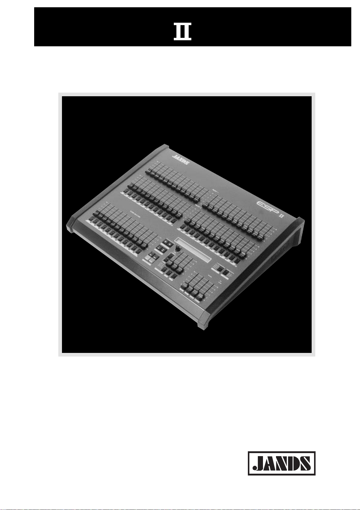
ESP II24/48/60
Lighting Control Consoles
Page 2

©1992 Jands Electronics
This instruction manual and the software described in it are copyrighted,
with all rights reserved. Under the copyright laws, this manual or the
software may not be copied, in whole or part, without the written consent
of Jands Electronics.
Technical Help and Support
If you have queries regarding the use of the ESP II or any other Jands
product, please contact us at:
Phone Australia (2) 9582 0909
9am and 5pm Australian Eastern Standard Time
Fax Australia (2) 667 4764
Email info@jands.com.au
Jands Electronics Pty Ltd
578 Princes Hwy
St Peters, NSW, AUSTRALIA
Phone +61 2 516 3622
Fax +61 2 517 1045
22
2
22
Page 3

Table of Contents
Getting Started.......................................................................................................... 4
Description of Major Parts ...................................................................................... 6
Using Presets........................................................................................................ 10
Using Flash Buttons............................................................................................. 11
Using theMaster Controls .................................................................................... 12
Using the Function Buttons ................................................................................. 14
The LCD Display Window .................................................................................. 15
Setup ........................................................................................................................ 16
Patch..................................................................................................................... 17
Desk ..................................................................................................................... 19
Linking Desks ...................................................................................................... 19
LCDs .................................................................................................................... 22
Utility ................................................................................................................... 23
Midi...................................................................................................................... 25
MCard .................................................................................................................. 27
Woring with Scenes ................................................................................................ 28
Editing Scenes...................................................................................................... 30
Woring with Chases ............................................................................................... 32
Editing Chases ..................................................................................................... 35
Woring with FX ...................................................................................................... 38
Editing FX............................................................................................................ 40
Woring with XF Cues............................................................................................. 42
Editing Xf Cues.................................................................................................... 44
Reset......................................................................................................................... 47
Appendix ................................................................................................................. 48
Index ........................................................................................................................ 52
3
Page 4

Getting Started
Connecting Power
Plug the socket end of the power cord into the IEC power receptacle
located on the rear face of the ESP II. The other end of the power cord
should be plugged into a 3 pin grounded outlet. It is important that the
ESP II is electrically grounded, if in doubt about whether or not an outlet
is grounded contact a licensed electrician.
Connecting the Output to a dimmer
ESP II provides two methods of connection to dimmer systems. The
DMX output is standard on all consoles. Optional Socapex output panels
can be simply fitted to the console to provide 0 - 10v wire-per-channel
outputs.
• DMX-512 Output
Connect from the consoles DMX output to the DMX input on the
dimmer rack, check the dimmer instruction manual for details on
selecting DMX Channels and looping the DMX line to other dimmer
racks.
Up to 512 dimmer channels can be controlled in this way.
• Analogue Outputs (Optional)
Connect from the consoles Socapex outputs to the dimmer rack input
Up to 8 Socapex connectors can be fitted to a console to provide up
to 240 dimmer channels
Connecting Desklights
Desklights are available as an optional accessory. Only Littlelite or
compatible desklights with 3 pin Cannon type connectors should be used.
4
Page 5

5
Page 6

0
0
0
Description of Major Parts
General Description of Major Parts
The front panel of the ESP II lighting control console is divided into 4
main areas. The top section consists of the Preset faders (A) and flash
buttons (B) which can be used both for direct control and recording. The
lower left section consists of the (C) Scene Master faders (D) and Scene
Flash buttons (E). The lower mid section consists of the LCD display (F),
the Function buttons (G) the Chase controls (H), the FX controls (I) and
the Xfade controls (J). The lower right section consists of the Master
controls for Preset 1, Preset 2, (K) Flash Buttons (L) and the Grand
Master (M).
The rear panel of the ESP II houses all the input and output connections
for power, control signals and desklights.
A The Preset Faders
Are used to set up channel levels both in operation and while recording. It’s possible to run a show entirely on the Presets but generally
these controls are used for programming or to make impromtu
changes to the stage lighting.
Event is available with 24
and 48 Channels. The
console can be set to wide
mode which doubles the
number of channels
E Flash Buttons
B The Flash Buttons (Channel)
Are used to momentarily flash on a channel. There is a flash button
for each channel when the desk is operating in the normal 2 preset
mode. However if the console is set to Wide mode, only the first half
has flash buttons.
PRESET 1
10
8
6
4
2
0
10
8
6
4
2
0
SCENE MASTERS
10
8
6
4
2
0
G Function buttonsD.E> Scene Masters
10
10
8
8
6
6
4
4
2
2
0
0
PRESET 2
10
10
8
8
6
6
4
4
2
2
0
0
CURSOR
10
8
6
4
2
0
0
10
-
+
8
RATE
VALUE
6
4
2
0
CHASE
CHASE FX
H Chase Controls
10
8
6
4
2
0
XF
FLASH
REVERSE
10
8
6
4
2
0
P1 P2
I, J FX and XF Controls
FLASH D.B.O.
MASTER
FLASH
1
8
6
4
2
0
1
8
6
4
2
0
ALL
SCENE
1
8
6
4
2
0
A. Preset Faders
BFlash Buttons
F . LCD
K. L. M
Master
Controls
6
Page 7

Description of Major Parts
D Scene Master Faders
E The Scene Flash Buttons
F The LCD Display
G The Function Buttons
The Scene Masters are used to fade Scenes up and down. They also
control Chases that have been Assigned to a Scene Master.
These buttons are used to momentarily flash on a Scene (or Chase).
The backlit LCD screens display the current Page, Chase, FX and
Xfade settings. It is also used to display various menus during editing
and console setup.
There are 8 buttons:
Left and Right Arrow - move the cursor in the LCD.
Plus (+) and Minus(-) - change values for Page, Chase, etc.
Edit - Press and hold Edit then press a Flash button to open the Edit
menu
Setup - Press to open the Setup menus.
Exit - Press to close a menu.
Record - Press and hold Record then press a Flash button to Record a
Scene, Chase, FX or Xf.
H The Chase Controls.
There are five controls in the Chase section:
A level fader
A Flash button which is used to run one cyle of the chase pattern and
to single step a stopped chase.
A rotary rate control
A direction button
An Assign button - Press the Assign switch then any Scene Flash
button to assign a Chase to the control of a Scene Master.
I The FX controls (Effects)
Intended for use in controlling color scrollers. The fader controls the
FX level while the Flash button is used to step through the FX. Up to
100 FX can be recorded.
J The Xfade controls (Crossfades)
These controls are used to run timed crossfades. The fader controls
the fade rate while the Flash button is used as the cue GO button. A
cue consists of an Xfade number (0-9) and a Q number (0-99).
7
Page 8

Description of Major Parts
K P1 and P2 Masters
L Flash Master Controls
M Grand Master
K Power Input
L Desklight Outlets
These 2 faders scale the level of the top (P1) and bottom (P2) presets.
The Flash Master fader scales the level of the flash buttons. The Add
/ Solo switch above this fader sets the method of operation for the
flash buttons.
Scales the level of all outputs (except the flash buttons).
Consists of an IEC power input complete with fuse and on/off switch.
Designed for use with Littelite or compatible desklamps
M DMX Output
Control output for connection to dimmer systems or interfaces using
DMX-512 protocol
N Midi
Control input allowing Midi signals to control various functions of
the console.
8
Page 9

9
Page 10

Using Presets
Preset Controls
The preset controls can be used to set up desired lighting levels both in
operation and while recording. It’s possible to run a show entirely on the
Presets but generally these controls are used for recording or to make
impromtu changes to the stage lighting.
Channel Preset Faders
There are 2 rows of presets faders on the ESP II, the top row of faders is
Preset 1 and the bottom row is Preset 2, these faders can be used to
smoothly fade a light to the desired level. The output level produced by
the preset faders is dependent on the level of the Grand Master and the
P1 (or P2) fader.
Example
Bring the Grand Master and P1 Master faders to 10 (100%).
Move the Channel 1 Preset fader to 100% and you should see the lights
connected to that channel fade up to full level.
Now fade up Channel 2 to 5 (50%), check that the lights connected to
channel 2 are at about 1/2 level.
Finally fade the P1 Master down and Up to see how it scales the Channel
Preset faders.
More Information.
Pg 20 Using all Preset faders as a single preset to obtain double the
number of channels
Pg 23 Reversing the P2 fader to provide 100% output when positioned
at 0
10
Page 11

Using Channel Flash Buttons
Channel Flash Buttons
These buttons correspond to the Channel faders and perform two functions:
1 Flash. The buttons are used to momentarily flash on a channel. The
type of operation (add, solo, latch) of the flash button depends on the
setting of the Add / Solo master switch
2 Inhibit. To prevent a channel from appearing in any output, hold the
Flash button down and press the DBO button. Repeat this procedure
to cancel inhibit.
11
Page 12

Using Masters Controls
P1 and P2 Faders
The P1 Master Fader scales the top row of preset faders, likewise the P2
Master Fader scales the overall level of the bottom row of preset faders.
By moving the P1 fader up while moving the P2 fader down it’s possible
to crossfade between the settings on the 2 rows of channel preset faders.
Add / Solo Master Switch
The Flash buttons can be set to operate in 3 different ways or turned off
completely. To change the operation of the flash buttons press the Add /
Solo switch. With each press of the button the 2 leds within the switch
change to indicate which mode has been selected.
• Add - Indicated by the Green Led being on. Pressing a FLASH button
causes that output to flash instantly to the level set by the Flash
Master fader.
• Add Latch - Indicated by the Green Led Flashing. The Flash buttons
push-on and push-off instead of flashing. When a Flash button is
latched on, the Channel LED will flash synchronously with the Add /
Solo switch LED. If Add Latch is disabled while some channels are
Latched, the channels will unlatch but will not become latched again
if Add Latch is subsequently enabled.
• Solo - Indicated by the Red Led being on. Pressing a Flash button
causes that output to flash instantly to the level set by the Flash
Master fader, while at the same turning off all other desk output.
• Disabled - Indicated by neither Led being on. Pressing a channel
Flash button has NO effect.
Add / Solo Fader
This fader scales the intensity of the flash buttons.
Grand Master Fader
Scales the intensity of all console outputs except the flash buttons.
D.B.O. Switch
This button performs two functions:
1 Blackout. Press to black out the output of the console. The button can
be set to momentary or latching operation.
12
2 Inhibit. To prevent a channel from appearing in any output, hold a
channel Flash button down and press the DBO button.
Page 13

Masters Controls
13
Page 14

The Function Buttons
➩
➩
O N
The Cursor Buttons
The left arrow and right arrow buttons are used to move the cursor to the
various fields in the LCD display window.
The Plus (+) On and Minus (-) Off Buttons
These buttons are used to change values. The plus button will either
increase a value or change a setting from off to on. Likewise the - button
will decrease values or change a setting from On to Off. These buttons
are also used in a few menus to toggle between several choices. These
buttons operate in three ways.
1 Press. The value increases by 1 with the + button or decreases by
1with the - button
2 Press and Hold. The value scrolls up with the + button or down with
the - button
3 Double Press. The value snap to the maximum for that field with the
+ button or to 0 with the the - button. It may take a couple of attempts
to double press at a fast enough speed to see this work.
EDIT
SETUP
X
D
The Edit Button
The EDIT button is used in conjuction with the Scene, Chase, FX and XF
flash buttons to open the Edit menu. Hold the button down for approxiametly 2 seconds to show a help message.
The Setup Button
The SETUP button is used to open the Setup Menus.
The Exit Button
The EXIT button is used to close the menu. Hold the button down for
approxiametly 2 seconds to show the ESP II software version number.
The Record Button
The RECORD button is in conjuction with the Scene, Chase, FX and XF
flash buttons to store levels.. Hold the button down for approxiametly 2
seconds to show a help message.
14
Page 15

LCD Window
The LCD display is used to perform two functions.
1 Normal Display.
In operation the LCD shows:
The current Page number.
The current Chase number and Step number.
The current FX number and the Next FX.
The current XF Q number and the Next XF Q.
• Changing a Setting
Use the arrow buttons to move the cursor to the required field. Use
the Plus (+) and Minus (-) buttons to set the field.
• Freeze Indication
When the Page or Chase field is flashing it indicates that the Page or
Chase number has been changed while the old Chase or a Scene was
set above zero. That fader will not change to the new Chase or Page
until it is faded to zero.
2 Menu Display.
A number of menus can be accessed to Setup the console and Edit
Scenes, Chases, FX and Xf Q.
Menu Fields
Page Number
Chase & Step
Number
Next FX
Current FX
Next XF:Q
Current
XF:Q
Page Chs:Step Next:FX Next X Q#
1 1 1 2 1 1: 2 1: 1
Settings
15
Page 16

Setup
Setup is used to perform various procedures which control the way the
console operates. The setup menu consists of 6 top level menus, some of
which have sub-menus. Some of the menus, such as PATCH and LCDs
are used to customise the desk while others such as MIDI are used to
extend the control cababilities of the ESP II.
When the SETUP button is pressed the Setup menu appears in the LCD
window. The Setup menu is illustrated below.
To open one of the Setup menus use the arrow buttons to select a menu
and then press the ON (+) buttons
The Setup Menu
16
Menu Fields
Set Ptch Desk Lcds Util Midi Mcrd
up +to◊ +to◊ +to◊ +to◊ +to◊ +to◊
Move the cursor & Press the Plus (+) button to open a submenu
Page 17

Setup Patch
The ESP II will control up to 512 dimmer channels. The Setup Patch
menu allows these dimmer channels to be patched in any combination
and at any level to the console channels.
Example:
A Patch is setup by first setting a console Channel number then setting
the Dimmer numbers to be connected to that channel. In the illustration
below Console Channel 1 is set to control Dimmer 1 at 100% (FF) and
Dimmer 10 at 100%. This means that when Channel 1 on the console is
faded up to 100% the lights connected to dimmers 1 and 10 will fade up.
The complete Patch consists of each Channel that is being used being set
to control one or more dimmer numbers. Since there are 3 different
Patchs available (1,2 & 3) its possible to set one Patch, which includes all
dimmers, for the main act and a different Patch which might not include
all dimmers for the support act. Similiarly if a light was knocked out of
focus during the show the Patch could be used to reduce the level of its
dimmer to 0 so that the light would not come on at any time.
The Setup Patch Menu
The Patch menu
Figure 13 illustrates the Patch menu. There are 4 fields:
Menu Fields
Patch Number
Channel
Dimmer
Level
Pch Ch Dim:At Dim:At Dim:At
1 1 1 FF 10 FF NC:FF
Settings
17
Page 18

Setup Patch
Pch (Patch Number)
Patch numbers range from 1 to 3. The Patch number shown is
active so care should be taken in changing the Patch number while
the console is in use.
Ch (Channel)
Sets the console Channel number to be patched. Only one channel
can be displayed at a time.
Dim (Dimmer)
Sets a dimmer number to patch to the Channel shown in CH.
At (At Level)
Sets the level of the dimmer set in the DIM field. At can be set
from 0 to FF (full).
The Default Patch
The default patch on the ESP II is Patch 1, it is a one-to-one patch. That
is Channel 1 connect to Dimmer 1, Channel 2 connect to Dimmer 2, and
so on. Dimmer numbers above the number of console channels are not
connected.
Patching Dimmers to Channels
A dimmer can only be patched to one channel at a time.
Storing Changes made in Patch
When all changes to a patch have been made, press the Record button to
save these changes and leave the Patch menu. If you press the Exit key
you are prompted to either save the changes by pressing the ON(+)
button or to abandon them by pressing the OFF (-) key.
18
Page 19

Setup Desk
The SETUP DESK menu is used to configure the ESP II to suit your
particular requirements and favored operating method. To open the Desk
menu, press the SETUP button, move the cursor to the DESK field and
press the PLUS (+) key.
Setup Desk
The menu consists of 5 fields (one being a submenu).
Mode
This feature is useful in protecting the ESP II against unauthorised use or
in restricting an inexperienced operator.
The Mode field can be toggled between PLAY and REC (Record). In the
PLAY mode it is not possible to Record, Edit or change Patch information.
Link
It’s possible to connect two ESP II consoles together by connecting a
special cable from the DMX output of the Slave console to the Midi input
of the Master console. For details on the wiring of this cable see the
appendix.
Once the two consoles are connected the LINK menu can be used - on
both consoles - to set one to Master operation and the other to Slave
operation.
To open the LINK menu, press the SETUP button, move the cursor to the
LINK field and press the PLUS (+) key, the Link menu consists of two
fields as follows:
TheSetup Desk Menu
Menu Fields
Link Submenu
Desk Mode
Desklight level
No of Presets
Wide
Setup Mode Link Lamp Wide Psets
Desk Rec +to◊ FF Off Dual
Settings
19
Page 20

Setup Desk
Master
When the MASTER field is set ON the MIDI IN socket can be used to
receive channel level information from the DMX output of a second ESP
II console. To use an ESP II as a Master console it must be set to WIDE
mode. If MASTER is turned on without WIDE being on a message will
be displayed offering the option of reseting the desk to WIDE but this
will clear the data already recorded.
When MASTER is turned ON the ESP II checks to see what extra channels are available (on the Slave console) and displays a message confirming the number of extra channels.
Slave
When the SLAVE field is set ON the DMX socket is used to send channel level information to the MIDI intput of a second ESP II console.
When a console is in Slave mode only the Preset faders and Flash buttons
are active.
Lamp (DeskLight)
The intensity of the Desklight(s) can be adjusted by setting the LAMP
field from 0 (0%) to FF (100%)
To set the Desklight level press SETUP move the cursor to the DESK
field; press the Plus (+) button move the cursor to the LAMP field and
enter a value between 0 and FF (Full) using the + and - buttons.
Wide
One of the most powerful features of the ESP II is its ability to work as a
single preset board outputing double the number of channels normally
available. In applications where Colour Scrollers or Moving Lights are
being controlled this feature greatly extends the usefullness of the console. An ESP II 24, for instance could control 48 colour scrollers.
WIDE should be turned on before recording. Once a console has been set
to WIDE the Preset 2 faders are used to control the higher numbered
channels. For example on an ESP 48 the Preset 2 faders would control
channels 49 to 96. The Preset 2 Master Fader is disabled.
Psets
The PSETS field is used to alter the operation of the bottom Preset faders
so that they can either be used as extra Preset 1 faders to control Wide
mode channels or as a regular second preset.
Setting the console to WIDE automatically switchs the Preset 2 faders to
20
Page 21

Setup Desk
SINGLE preset usage (i.e. the P2 faders control the extra channels.
However it is possible to switch the P2 faders to operate as a normal
second preset by changing the PSETS field to DUAL.
In this way it’s possible to Record Scenes, FX Cues and Chases using all
the faders as a single preset but having done so to switch back to having
two manual presets for the first half of the channels. This method is
particularly useful for controlling Colour changers and other moving
lights which once recorded do not need direct control.
To change the PSETS field to SINGLE (or back to DUAL) move the
cursor to the PSETS field and press the ON (+) button.
Figure7
The Setup Desk Link Menu
Menu Fields
Master Field
Slave Field
Link Master Slave
Off Off
Settings
21
Page 22

Setup LCDs
TheLCD located on the front panel of the ESP II can be configured to
suit different lighting conditions and viewing angles.
The LCD Menu
To open the LCD menu move the cursor to the LCD field and press the +
key. The menu contains 3 fields.
Cursor
This field can be toggled between Block and Line by pressing the
plus (+) or minus (-) button. Generally a block cursor is easier to
locate in a menu.
Contrast
This field can be set to any value between 0 and 15 using either
the numeric keypad or the + and - buttons. Higher contrast settings tend to make the LCDs more legible from lower viewing
angles.
Figure8
The Setup LCDs Menu
Bright
This field can be set to any value between 0 and 15 using either
the numeric keypad or the + and - buttons. At 0 there is no backlighting of the LCDs, at 15 maximum backlighting is provided.
Backlighting should always be used in low ambient light conditions but can be turned of if the console is in direct sunlight.
Menu Fields
Cursor type
LCD Contrast
LCD Brightness
SETUP Cursor Contrast Bright
LCDs Block 8 8
22
Settings
Page 23

Setup Util
The SETUP UTIL (Utility) menu is used to configure various ESP II
controls to suit your preffered operating method. To open the Util menu,
press the SETUP button, move the cursor to the UTIL field and press the
ON (+) key, the menu consists of four fields as follows:
P1/2
Many operators who use the Preset faders while running a show prefer to
move the 2 Preset Master faders together, with one hand, to crossfade
between Presets. To allow this on an ESP II the Preset 2 Master fader
can be reversed such that at the top of its travel output from Preset 2 is
zero (0) and at the bottom of its travel the output is 100%.
To change the P1/2 field to REV (Reverse) move the cursor to the P1/2
field and press the Plus (+) button. Pressing the Plus (+) button again will
toggle between NORM (Normal) and REV (Reverse)
D.B.O. (Dead Black Out)
The DBO button can be set to either momentary or latching operation. To
alter DBO operation move the cursor over the DBO field and press either
the On (+) or Off (-) key. The possible settings are:
Momt
Momentary operation, the console is Blacked Out only while the DBO
button is held depressed.
Ltch
Latching, the console is Blacked Out by pressing the DBO button.
Output is restored when the DBO button is pressed again.
The Setup Utilities Menu
Menu Fields
Preset 2 Master Fader Operation
DBO Type
VDU Type Master Type
Setup P1/2 dbo Video GMast
Util Normal Momt Mono Hold more
Settings
23
Page 24

Setup Util
Video
An optional panel is available which allows a Video monitor to be connected to the console. The Video field is used to configure the ESP II
output to suit a variety of different monitor types. To change the Video
field move the cursor over the VIDEO field and press either the On (+) or
Off (-) key. The possible settings are:
Mono To suit monochrome monitors
CGA To suit monitors designed for a Composite Graphic Adaptor
EGA To suit monitors designed for a Extended Graphic Adaptor
GMaster
This field is used to set the operation of the Grand Master fader. To
change setting move the cursor over the GMAST field and press either
the Plus (+) or Minus (-) key. The possible settings are:
Scn - The fader scales the level of the Scene Masters
All - The fader scales all console outputs except the Flash buttons.
The Setup Utilities Menu
Infade (move the cursor to the More field to open this field)
Sets the default Infade time. This time will be automatically applied to all
cues (XF:Q) as they are recorded.
Infade time can be set anwhere in the range 0 to 99 minutes 59 seconds.
The infade time determines how long it will take for the Q to fade from
zero to 100%
Outfde (move the cursor to the More field to open this field)
Sets the default Outfade time. This time will be automatically applied to
all cues (XF:Q) as they are recorded.
Outfade time can be set anwhere in the range 0 up to 99 minutes 59
seconds. The outfade time determines how long it will take for the Q to
fade from 100% to zero.
Menu Fields
Default Infade Time
Default Outfade Time
24
Setup Infade Outfade
Util 0M05S 0M05S
Settings
Page 25

Setup Midi
The Musical Instrument Digital Interface MIDI is a well established
standard which allows communication between suitably equipped devices. The ESP II is equipped with a MIDI input socket which is used to
allow Midi control of various console functions. To select the MIDI
menu move the cursor to the MIDI field and press the ON (+) key.
Midi
The Midi field must be turned ON for Midi to be used. The Midi interface can be configured (using the other menu fields) to suit your requirements and then turned On and Off as required.
Midi-Ch (Channel)
MIDI information can be broadcast on any of 16 channels, to set which
channel the ESP II will ‘listen’ to enter a value between 1 and 16
Prog (Midi Program Change Messages)
The ESP II responds to MIDI Program Change information, Program
change messages can be used to activate the XF section
For example if Midi Program Change message 25 is received, XF 1 Q 25
will play on the XF master.
Figure11
TheMidi Menu
Scene (Scene Fader Number)
Sets the Scene flash button to be triggered by the Note set in the Note
field. Each Scene Master can be set to respond to a different note, to do
this step through the Scene field setting each fader to the desired note.
The Scene / Note fields update immediately and there is no need to press
Record to save changes.
Menu Fields
Midi On/Off
Midi Channel
Midi Program Messages
Midi Note
Assign Fader
Midi Midi-Ch Program Scene Note
Off 1 Off 1 48
Settings
25
Page 26

Setup Midi
Note (Midi Note Message)
Midi allows for 128 Note messages to be broadcast. The NOTE field is
used to set which of the 128 Notes will be associated with each of the 12
Scene Masters. Whenever a note that has been specified in this menu is
received it will be equivalent to pressing the SCENE Flash button.
First set the Scene field from 1 to 12 and then set the NOTE field from 1
through 128 - corresponding to the 128 Midi Notes.
If you don’t want to use Midi NOTE messages on a particular Scene
master set the NOTE field to zero (displayed as OFF). To set the field to
off, enter a zero or double click on the minus (-) key.
26
Page 27

Setup MCard
The ESP II MCard is an optional accessory which allows all the information recorded in the console to be saved to a compact ramdisk. Anyone
who regularly runs the same show is strongly advised to fit an MCard. It
is not possible to access the MCard menu unless the console is fitted with
the MCard panel.
The MCard Menu
To open the MCard menu move the cursor to the MCard field and press
the + key. The menu contains 2 fields:
To MCard
To select this option and save the desk data To the Mcard move the
cursor to the TO MCARD field and press the Plus (+) key.
From MCard
To select this option and load data to the desk move the cursor to the
FROM MCARD field and press the Plus (+) key.
Saving to the MCard.
To save the information recorded in the ESP II follow these steps.
1. Insert a MCard in the rear panel slot, ensure that the MCard battery is
fitted and the write enable switch is on
2. Open the MCARD menu as detailed above.
3. Move the cursor to the TO MCARD field and press +
4. A record confirmation screen shows.
Loading from the MCard.
When information is loaded from a MCard all Scenes, Chases and
Patches are overwritten.
To retreive information recorded on a MCard to the ESP II , follow these
steps.
1. Insert the recorded MCard in the rear panel slot, ensure that the MCard
battery is fitted and the write enable switch is on
2. Open the MCARD menu as detailed above.
3. Move the cursor to the FROM MCARD field and press +
4. A loaded confirmation screen shows.
IMPORTANT
Insert the M-Card only when transferring data
The M-Card may be corrupted if the desk is turned on or off with the MCard in the console.
27
Page 28

Working with Scenes
The ESP II can record 10 Pages of 12 Scenes each for a total of 120
Scenes.
Note:
Scenes can only be recorded when the desk is
set to RECORD mode.
Setting the Page Number
• Use the arrow buttons to move the cursor to the Page field.
• Use the Plus (+) and Minus (-) buttons to set the required Page
number.
Freeze
When the Page field is flashing it indicates that the Page number has
been changed while a Scene Master was set above zero. That fader
will not change to the new Page until it is faded to zero.
The Scene Controls
There are 12 Scene Master faders and 12 Flash buttons
Fader
The fader controls the level of the level of a Scene ranging from 0 to
100%.
Flash Buttons
These buttons correspond to the Scene faders and perform two functions:
1 Flash. The buttons are used to momentarily flash on a Scene.
28
2 Record. To Record a Scene, set up the desired output, hold the
Record button down and press a Scene Flash button.
LCD Display
The display shows the current Page number
Recording a Scene - Record and Point
• Use the arrow buttons to move the cursor to the Page field.
• Use the Plus (+) and Minus (-) buttons to set the required Page
number.
• Use the Preset faders (and any other console controls) to set up the
lighting output required.
• Hold the Record button down and press the Flash button (beneath the
Scene fader)*.
• A message displays on the LCD showing the number of items recorded and how many are still available.
• Release both buttons.
Page 29

Working with Scenes
NB
* If the LED in the Flash button comes on when the Record button is
pressed that scene has already been recorded. Proceeding will record
over the old scene.
More Information
Pg 30 Editing an Scene
Pg 30 Blind Recording using the EDIT SCENE menu.
Menu Fields
Page Number
Page Chs:Step Next:FX Next X Q#
1 1 1 2 1 1: 2 1: 1
Settings
29
Page 30

Editing a Scene
Note:
The Edit Scene menu is
only available when the
desk is set to RECORD
mode.
Editing a Scene
A Scene can be edited to change the levels of chanels or groups of channels. Editing can be carried out ‘blind’, that is, without the changes being
seen on stage or ‘live’.
• Hold the EDIT button down and press the Scene Flash button.
• Either use the Preset 1 (top preset) faders to set new levels or enter
Channel numbers and levels directly into the Edit Scene menu. For
detailed explanations of this step refer to the Edit Scene Menu section
below.
• When all changes have been made press the RECORD button.
• A message displays on the LCD showing the number of items recorded and how many are still available for future recording.
N.B.
Whenever the EDIT SCENE menu is opened the Preset faders are disabled from outputing to the stage. However they can be used to set levels
for the item being edited.
Recording Changes made in Edit
To save the changes made using EDIT press the RECORD button. It is
not necessary to press record after each channel (or group of channels) is
set to a new level.
Live and Blind Editing
The ESP II allows edits to be carried out Live or Blind. An edit will be
Live if that Scene is currently being outputed to the Stage (by one of the
Scene Masters) otherwise it will be blind.
Editing a Scene not on the current Page
It’s possible to blind Edit a Scene which is not currently on the Scene
Masters.
• Hold the EDIT button down and press ANY Scene Flash button.
• Move the cursor to the PG field and set the required Page number.
• Move the cursor to theSC field and set the required Scene number.
• Use the procedure described above to perform a blind edit
The Edit Scene Menu
The illustration below shows the EDIT SCENE menu. There are 5 fields
in the Scene menu:
30
Page 31

Editing a Scene
PG: (Page Number)
Page number sets the Page of the Scene to be edited. To change
this number move the cursor to The PG: field and use the Plus (+)
and Minus (-) buttons to change the number.
SC: (Scene Number)
Sets the Scene to be edited. To change this number move the
cursor to The SC: field and use the Plus (+) and Minus (-) buttons
to change the number.
CH (Channel)
Can be set using the Plus (+) and Minus (-) buttons or by moving
any of the TOP preset faders. Moving a top preset (P1) fader sets
the channel (CH) field to that number.
TO Can only be changed by using the Plus (+) and Minus (-) buttons
(the slider method is not available). Changes to level will effect all
channels from the CH number to the TO number, inclusive.
TheEdit Scene Menu
AT Used to set a new level for the Channel or channels set by the CH
and TO fields. AT can be changed by using the Plus (+) and
Minus (-) buttons or by moving the TOP preset fader until its level
matches the previously recorded level. Once a match has been
acheived the slider takes control of the level and can be used to set
the AT field.
For the slider to ‘take control’ of a channel recorded at Zero level
(AT=0) it is necessary to move the slider above zero, to select the
channel, then back to zero to match the level, then to the new level
setting.
Menu Fields
Page Number
Scene Number
Channel to Edit
End of Channel Range
Level
Edit Pg:Sc Ch To At
Scene 1 12 1 12 FF
Settings
31
Page 32

Working with Chases
The ESP II can record 10 Chases numbered 0 - 9.
Setting the Chase Number
• Use the arrow buttons to move the cursor to the Chase field.
• Use the Plus (+) and Minus (-) buttons to set the required Chase
number.
Freeze
When the Chase field is flashing it indicates that the Chase number
has been changed while the old Chase was set above zero. That fader
will not change to the new Chase until it is faded to zero.
The Chase Controls
Are used to set the speed, direction and level of the Chase number displayed in the LCD window. Once a Chase is set it can be Assigned to a
Scene Master.
Fader
The fader controls the level of the chase ranging from 0 to 100%.
Flash Button
The Flash button, when pressed, resets the Chase to step 1 and runs the
Chase from the first to the last step. The Flash Master switch must be in
the ADD, ADD LATCH or SOLO position and the Chase level will be
dependent on the setting of the Flash master fader.
Rate
The Rate pot can be used to speed up or slow down a Chase. Turning it
fully counter clockwise will slow the chase to a STOP, turning it fully
clockwise will increase the speed to the maximum speed.
Chase Direction
The Direction button is used set the direction of the Chase. Push the
button to change the setting. With each press of the button the direction
changes to one of the following:
>> - Forward Green Led On
<> - Bounce Both Leds On
<< - Reverse Red Led On
Rn - Random Neither Led On
32
Page 33

Working with Chases
Single Stepping a Chase
To single step a Chase, first reduce the chase speed to zero (0) by turning
the rate override pot fully counter clockwise. Then use the Flash button
to step the Chase.
Assign
The Assign button is used to Assign (or transfer) a Chase to the control
of a Scene Master. Press the Assign button then press a Scene Master
Flash button, the Chase is assigned to that fader. The Chase speed and
direction should be set before assigning as the Scene controls only
provide control of level.
To Unassign a Chase from a Scene master press and hold the Exit button
while pressing that Scene master flash button.
Recording a Chase - Record and Point
• Use the arrow buttons to move the cursor to the Chase field.
• Use the Plus (+) and Minus (-) buttons to set the required Chase
number.
• Use the Preset faders (and any other console controls) to set up the
lighting output required for the first step of the Chase.
• Hold the Record button down and press the Flash button (beneath the
Chase fader).
• A message displays on the LCD showing the number of items recorded and how many are still available.
• Release both buttons.
• Set up the output required for the second step of the Chase.
• Hold the Record button down and press the Flash button (beneath the
Chase fader).
• A message displays on the LCD showing the number of items re-
Menu Fields
Chase Number
Step Number
Page Chs:Step Next:FX Next X Q#
1 1 1 2 1 1: 2 1: 1
Settings
33
Page 34

corded and how many are still available.
• Release both buttons.
• Repeat the last three steps for each subsequent step of the Chase.
NB
* When the Record button is pressed, the Chase STEP field stops count-
ing and automatically changes to allow a new step to be added.
Setting the Chase Step to Record
It is possible to record over an existing Chase step by stopping the Chase.
• Use the Rate control to stop the Chase. (Turn fully counter clockwise)
• Use the Chase flash button to Step the Chase to the required step
• Use the Preset faders (and any other console controls) to set up the
lighting output required for the first step of the Chase.*
• Use the Preset faders (and any other console controls) to set up the
lighting output required
• Hold the Record button down and press the Flash button (beneath the
Chase fader).
• A message displays on the LCD showing the number of items recorded and how many are still available.
• Release both buttons.
34
NB
* If the Chase fader is up any changes will be added to the old step. To
completely replace the step ensure the Chase fader is at zero when
recording.
More Information
Pg # Editing a Chase
Pg # Blind Recording using the EDIT CHASE menu.
Page 35

Editing a Chase
Editing a Chase
A Chase can be edited to change the levels of chanels or groups of channels. Editing can be carried out ‘blind’, that is, without the changes being
seen on stage or ‘live’.
• Stop the Chase on the Step to be edited.
• Hold the EDIT button down and press the Chase Flash button.
• Either use the Preset 1 (top preset) faders to set new levels or enter
Channel numbers and levels directly into the Edit Chase menu. For
detailed explanations of this step refer to the Edit Chase Menu section
below.
• When all changes have been made press the RECORD button.
• A message displays on the LCD showing the number of items recorded and how many are still available for future recording.
N.B.
Whenever the EDIT CHASE menu is opened the Preset faders are disabled from outputing to the stage. However they can be used to set levels
for the item being edited.
Recording Changes made in Edit
To save the changes made using EDIT press the RECORD button. It is
not necessary to press record after each channel (or group of channels) is
set to a new level.
Live and Blind Editing
The ESP II allows edits to be carried out Live or Blind. An edit will be
Live if that Chase is currently being outputed to the Stage otherwise it
will be blind.
Editing a Chase not on the Chase Master
It’s possible to blind Edit a Chase which is not currently on the Chase
Master.
• Hold the EDIT button down and press the Chase Flash button.
• Move the cursor to the CHS: field and set the required Chase number.
• Move the cursor to the ST field and set the required Chase Step
number.
• Use the procedure described above to perform a blind edit
Adding a Step
• Set the ST (step) field to the step number that you wish to add.
35
Page 36

Editing a Chase
Note:
The Edit Chase menu is
only available when the
desk is set to RECORD
mode.
When a step is added it pushes all the old steps which had an equal or
higher number one number higher. For example when adding a new
first step set ST to 1. The old step 1 will become step 2, the old step 2
will become 3 and so on.
• Move the cursor to the ADD field and press the ON (+) button.
• Press the ON (+) button again to confirm the Add.
Note - Adding the step does NOT record any levels.
• After adding the step either use the faders or the CH and AT fields to
set the required Channel levels
• Press RECORD.
Deleting a Step
• Set the ST (step) field to the step number that you wish to remove.
• Move the cursor to the DEL field and press the ON (+) button.
• Press the ON (+) button again to confirm the Delete.
• Press Exit to close the menu.
The Edit Chase Menu
The illustration over shows the EDIT CHASE menu. There are 5 fields in
the Chase menu:
CHS: (Chase Number)
Sets the Chase to be edited. To change this number move the
cursor to The CHS: field and use the Plus (+) and Minus (-) buttons to change the number.
ST (Step)
Sets the Step to be edited.
OF (Number of Steps)
Indicates how many steps recorded in this Chase
CH (Channel)
Can be set using the Plus (+) and Minus (-) buttons or by moving
any of the TOP preset faders. Moving a fader sets the channel
(CH) field to that number.
TO Can only be changed by using the Plus (+) and Minus (-) buttons
(the slider method is not available). Changes to level will effect all
channels from the CH number to the TO number, inclusive.
36
AT Used to set a new level for the Channel or channels set by the CH
Page 37

Editing a Chase
and TO fields. AT can be changed by using the Plus (+) and
Minus (-) buttons or by moving the TOP preset fader until its level
matches the previously recorded level. Once a match has been
acheived the slider takes control of the level and can be used to set
the AT field.
For the slider to ‘take control’ of a channel recorded at Zero level
(AT=0) it is necessary to move the slider above zero, to select the
channel, then back to zero to match the level, then to the new level
setting.
ADD (Add)
The ADD field is used to Add a step to a chase. Move the cursor
to the ADD field and press ON (+).
DEL (Delete)
The DEL field is used to delete a step to a chase. Move the cursor
to the DEL field and press ON (+).
Figure 21
The Edit Chase Menu
Menu Fields
Chase Number
Number of Steps Recorded
Channel
Step
Range
Delete
Edit Chs: St Of Ch To At Del
Add
Chs 6 1 6 12 12 50 Off
Off
Settings
Add
37
Page 38

Working with FX
Console output can be recorded to the FX section in the same way as
Scenes are recorded. Up to 100 FX, which are intended for controlling
colour scrollers or other effects, can be recorded and then played back in
any order.
The FX Controls
Fader
The fader controls the level of the FX output ranging from 0 to 100%.
Flash Button
This button corresponds to the FX fader and performs two functions:
1 GO. The button is used to step through the recorded FX numbers.
2 Record. To Record an FX, set up the desired output, hold the Record
button down and press the FX Flash button.
LCD Display
The display above the FX fader shows the current FX output number and
the Next FX Press the flash button to activate the Next FX.
Recording a FX - Record and Point
• Use the arrow buttons to move the cursor to the FX field.
• Use the Plus (+) and Minus (-) buttons to set the FX number.
• Use the Preset faders (and any other console controls) to set up the
lighting output required.
• Hold the Record button down and press the FX Flash button (beneath
the FX fader).
• A message displays on the LCD showing the number of items recorded and how many are still available.
• Release both buttons.
Changing the Playback Order
FX play back in numerical sequence, FX 2 follows FX 1 and so on. Any
unrecorded number is ignored, so if only FX 10, 20, 30, 40 are recorded,
presssing the flash button will step through 10, 20, 30, 40 and then loop
back to 10. To change the order:
38
• Use the arrow buttons to move the cursor to the NEXT FX field.
• Use the Plus (+) and Minus (-) buttons to set the required FX number.
Page 39

Working with FX
• Press the FX Flash button.
More Information
Pg 40 Blind Recording using the EDIT FX menu.
Menu Fields
Next FX
Current FX
Page Chs:Step Next:FX Next X Q#
1 1 1 2 1 1: 2 1: 1
Settings
39
Page 40

Editing FX
Editing a FX
A FX can be edited to change the levels of channels or groups of channels. Editing can be carried out ‘blind’, that is, without the changes being
seen on stage or ‘live’.
• Hold the EDIT button down and press the FX Flash button.
• Either use the Preset 1 (top preset) faders to set new levels or enter
Channel numbers and levels directly into the Edit FX menu. For
detailed explanations of this step refer to the Edit FX Menu section
below.
• When all changes have been made press the RECORD button.
• A message displays on the LCD showing the number of items recorded and how many are still available for future recording.
N.B.
Whenever the EDIT FX menu is opened the Preset faders are disabled
from outputing to the stage. However they can be used to set levels for
the item being edited.
Recording Changes made in Edit
To save the changes made using EDIT press the RECORD button. It is
not necessary to press record after each channel (or group of channels) is
set to a new level.
Live and Blind Editing
The ESP II allows edits to be carried out Live or Blind. An edit will be
Live if that FX is currently being outputed to the Stage (by the FX Master) otherwise it will be blind.
Changing the FX number to Edit
It’s possible to blind Edit a FX which is not currently on the FX Masters.
• Hold the EDIT button down and press the FX Flash button.
• Move the cursor to the FX field and set the required FX number.
• Use the procedure described above to perform a blind edit
The Edit FX Menu
The illustration below shows the EDIT FX menu, press the EDIT button
followed by the FX button to see this menu. There are 4 fields in the FX
menu:
40
FX: (FX Number)
Sets the FX to be edited. To change this number move the cursor
Page 41

to The FX: field and use the Plus (+) and Minus (-) buttons to
change the number.
CH (Channel)
Can be set using the Plus (+) and Minus (-) buttons or by moving
any of the TOP preset faders. Moving a fader sets the channel
(CH) field to that number.
TO Can only be changed by using the Plus (+) and Minus (-) buttons
(the slider method is not available). Changes to level will effect all
channels from the CH number to the TO number, inclusive.
AT Used to set a new level for the Channel or channels set by the CH
and TO fields. AT can be changed by using the Plus (+) and
Minus (-) buttons or by moving the TOP preset fader until its level
matches the previously recorded level. Once a match has been
acheived the slider takes control of the level and can be used to set
the AT field.
For the slider to ‘take control’ of a channel recorded at Zero level
(AT=0) it is necessary to move the slider above zero, to select the
channel, then back to zero to match the level, then to the new level
setting.
Figure 20
The Edit FX
Menu Fields
FX Number
Channel to Edit
Edit FX Ch To At
FX 1 1 11 FF
Settings
Level
41
Page 42

Working with XF Cues
Console output can be recorded to the crossfade (XF) section in the same
way as Scenes are recorded. There are 10 XF stacks each comprising 100
cue (Q) numbers.
Note:
The Chase menu is only
available when the desk is
set to RECORD mode.
The XF Controls
Fader
The fader is used to take manual control of a crossfade. The fader should
be fully up (at the 10 position) for the crossfade to run normally.
Flash Button
This button corresponds to the XF fader and performs two functions:
1 GO. The button is used to begin a crossfade.
2 Record. To Record a Q, set up the desired output, hold the Record
button down and press the XF Flash button.
LCD Display
The display above the XF fader shows the current XF stack / Q number
and the Next XF / Q number Press the flash button to begin a timed
dipless crossfade from one to the other. When a crossfade is running the
display shows the time to run in seconds and the elapsed fade percentage.
If the display shows 5 / 50% it indicates that there is 5 seconds to run and
the fade is 50% complete.
Recording a Q - Record and Point
• Use the arrow buttons to move the cursor to the XF field.
• Use the Plus (+) and Minus (-) buttons to set the XF number.
• Use the arrow buttons to move the cursor to the Q field.
• Use the Plus (+) and Minus (-) buttons to set the Q number.
• Use the Preset faders (and any other console controls) to set up the
lighting output required.
• Hold the Record button down and press the XF Flash button (beneath
the XF fader).
• A message displays on the LCD showing the number of items recorded and how many are still available.
• Release both buttons.
42
Changing the Playback Order
Qs play back in numerical sequence, XF/Q 1:2 follows XF/Q 1:1 and so
on. Any unrecorded number is ignored, so if only XF/Q 1:10, 1:20, 1:30,
1:40 are recorded, each press of the flash button will fade from 1:10 to
1:20 to 1:30 to 1:40 and then loop back to 1:10. To change the order:
• Use the arrow buttons to move the cursor to the NEXT XF/Q field.
Page 43

Working with XF Cues
• Use the Plus (+) and Minus (-) buttons to set the required XF/Q
number.
• Press the FX Flash button.
Taking Manual Control of a Fade
To take manual control of a crossfade move the fader to match the
elapsed fade percentage. The display changes to show MAN: / 20% (or
whatever fade percentage has elapsed)
The fader can now be moved up or down to control the progress of the
fade. If the level is taken to 100% the fade is completed and the fader
reverts to level control.
To take manual control from the beginning of the cue pull the fader down
to zero (0) before pressing the flash button
Leaving the fade under manual control means that all subsequent cues
will come under manual control when the fade percentage reaches the
fader setting. Thus if XF/Q 1:10 was taken under control after 50% of the
fade time had elapsed it would stay on at 50%. If the fader was left at this
level the next press of GO would cause the next Q to fade to 50% and
XF/Q 1:10 to fade from 50% to 25% (i.e. 50% of 50%.
Fade Times
The default fade time, normally 5 seconds, is set in the SETUP UTIL
menu, all Qs are recorded with this Infade and Outfade time. However
fade times can be changed for each Q by using the EDIT XF menu.
More Information
Pg 44 Blind Recording using the EDIT XF menu.
Pg 44 Setting fade times using the EDIT XF menu.
Pg 24 Setting the default fade times.
Menu Fields
Page Number
Chase & Step
Number
Next FX
Current FX
Next XF:Q
Current
XF:Q
Page Chs:Step Next:FX Next X Q#
1 1 1 2 1 1: 2 1: 1
Settings
43
Page 44

Editing a XF Cue
Editing a Crossfade Cue
A Crossfade (XF) Cue (Q) can be edited to change the levels of chanels
or groups of channels. Editing can be carried out ‘blind’, that is, without
the changes being seen on stage or ‘live’.
• Hold the EDIT button down and press the XF Flash button.
• Either use the Preset 1 (top preset) faders to set new levels or enter
• When all changes have been made press the RECORD button.
• A message displays on the LCD showing the number of items re-
N.B.
Whenever the EDIT XF Q menu is opened the Preset faders are disabled
from outputing to the stage. However they can be used to set levels for
the item being edited.
Channel numbers and levels directly into the Edit XF Q menu. For
detailed explanations of this step refer to the Edit XF Q Menu section
below.
corded and how many are still available for future recording.
Recording Changes made in Edit
To save the changes made using EDIT press the RECORD button. It is
not necessary to press record after each channel (or group of channels) is
set to a new level.
Live and Blind Editing
The ESP II allows edits to be carried out Live or Blind. An edit will be
Live if that XF Q is currently being outputed to the Stage (by one of the
XF Q Masters) otherwise it will be blind.
Editing a XF Q not on the current Page
It’s possible to blind Edit a XF Q which is not currently on the XF Q
Masters.
• Hold the EDIT button down and press the XF Q Flash button.
• Move the cursor to the XF field and set the required XF number.
• Move the cursor to theQ# field and set the required XF Q number.
• Use the procedure described above to perform a blind edit.
Changing Fade Times
Fade times can be changed at any time without re-recording the Scene.
44
• Open the Edit XF Q menu
• Use the arrow buttons to move the cursor to the Infade field.
Page 45

Editing a XF Cue
• Enter an Infade time of up to 99Minutes 59Seconds using the + and buttons to change the existing value.
• Use the arrow buttons to move the cursor to the Outfade field.
• Enter an Outfade time of up to 99Minutes 59Seconds using + and buttons to change the existing value.
• Press the EXIT button.
• Do NOT press the Record button, if only entering or changing the
fade times.
The Edit XF Q Menu
The illustration below shows the EDIT XF Q menu. There are 5 fields in
the XF Q menu:
XF: (Crossfade Stack Number)
Sets the Stack number of the Q to be edited. To change this
number move the cursor to The XF: field and use the Plus (+) and
Minus (-) buttons to change the number.
Figure 20
The Edit Xf Cue
Q: (XF Q Number)
Sets the Q to be edited. To change this number move the cursor to
The Q#: field and use the Plus (+) and Minus (-) buttons to change
the number.
CH (Channel)
Can be set using the Plus (+) and Minus (-) buttons or by moving
any of the TOP preset faders. Moving a fader sets the channel
(CH) field to that number.
TO Can only be changed by using the Plus (+) and Minus (-) buttons
(the slider method is not available). Changes to level will effect all
channels from the CH number to the TO number, inclusive.
Menu Fields
XF Number
Cue Number
Channel to Edit
Level
Fade Times
Edt XF:Q# Ch To At Infade Outfde
Cue 1: 1 1 1 FF 0M05S 0M05S
Settings
45
Page 46

Editing an Xf Cue
AT Used to set a new level for the Channel or channels set by the CH
and TO fields. AT can be changed by using the Plus (+) and
Minus (-) buttons or by moving the TOP preset fader until its level
matches the previously recorded level. Once a match has been
acheived the slider takes control of the level and can be used to set
the AT field.
For the slider to ‘take control’ of a channel recorded at Zero level
(AT=0) it is necessary to move the slider above zero, to select the
channel, then back to zero to match the level, then to the new level
setting.
Infade (Infade Time)
Infade time can be set anwhere in the range 0 to 99 minutes 59
seconds. The infade time determines how long it will take for the
Q to fade from zero to 100%
Outfde (Outfade Time)
Outfade time can be set anwhere in the range 0 up to 99 minutes
59 seconds. The outfade time determines how long it will take for
the Q to fade from 100% to zero.
46
Page 47

Reset
Reset is used to reset the console and optionally clear all data including
Scenes, Chases, FX, XF, and Patches. Reset can be used to quickly erase
all data that has been recorded in an ESP II.
To Reset the console
• Hold the DBO and FLASH Master buttons down while turning power
on to the console.
• Press the RECORD button to confirm the console Reset.
• All data is cleared from the console and all settings revert to the
factory set defaults.
Reset ALL Data will be lost!!
Console RECORD to confirm
47
Page 48

Appendix 1 - Pin Assignments
DMX Digital
Output Socket
Midi In Socket
PIN No Signal
1 SHIELD
2 SIGNAL 3 SIGNAL +
4 NOT USED
5 NOT USED
Connector type: Cannon 5 pin XL
RS-485 Standard USITT DMX-512 Protocol
PIN No Signal
1 NOT USED
2 NOT USED
3 NOT USED
4 MIDI +
5 MIDI SIGNAL
Desklight Socket
Connector type: Din 5 pin
PIN No Signal
1 No Connection
2 Ground
3 0 - 12 volts +
Connector type: Cannon 3 pin XL
48
Page 49

Desk Link Cable
To link two ESP II consoles together connect a cable, wired as detailed below between the
DMX output of the desk to be the slave to the MIDI input on the desk to be used as
Master.
Cannon 5 Pin Din 5 Pin
PIN No PIN No
2 390R 1/4w 5% 4
45
Power
Requirements90 volts to 265 volts AC, 50-60 Hz
Consumption 40 watts (85 watts with analog outputs)
Connector IEC 3-pin inc. fuse, switch and mains filter
Fuse 2 amp M205
Midi Note Messages
Midi Note messages run from 0 to 127.
Midi Note Midi Note Midi Note Midi Note Midi Note Midi Note
36 C1 48 C2 60 C3 72 C4 84 C5 96 C6
37 C#1 49 C#2 61 C#3 73 C#4 85 C#5 97 C#6
38 D1 50 D2 62 D3 74 D4 86 D5 98 D6
39 D#1 51 D#2 63 D#3 75 D#4 87 D#5 99 D#6
40 E1 52 E2 64 E3 76 E4 88 E5 100 E6
41 F1 53 F2 65 F3 77 F4 89 F5 101 F6
42 F#1 54 F#2 66 F#3 78 F#4 90 F#5 102 F#6
43 G1 55 G2 67 G3 79 G4 91 G5 103 G6
44 G#1 56 G#2 68 G#3 80 G#4 92 G#5 104 G#6
45 A1 57 A2 69 A3 81 A4 93 A5 105 A6
46 A#1 58 A#2 70 A#3 82 A#4 94 A#5 106 A#6
47 B1 59 B2 71 B3 83 B4 95 B5 107 B6
49
Page 50

Index
A
Add 12
Add / Solo Master Switch 12
Add Latch 12
Adding a Step 35
Analogue 4
Assign 33
B
Black Out) 23
Blind 35, 40
Blind Editing 30
Bright 22
C
Chase 32
Chase Controls 7, 32
Connecting Desklights 4
Connecting Power 4
Connecting the Output to a
dimmer 4
Contrast 22
Crossfade 42
Cues 42
Cursor 22
D
D.B.O. 12, 23
Deleting a Step 36
Desk Link Cable 49
DeskLight 20
Desklight 8
Display 15
DMX 48
DMX Output 8
DMX-512 4
E
Edit Button 14
Edit File 40
Edit FX 40
Editing a Chase 35, 36
Editing a Cue 44
Editing a FX 40
Editing a Scene 30
F
Fade Times 43, 44
Fader 42
Flash Buttons 6, 11
Flash Master Controls 8
Flashing LCD 15
Freeze 15, 28
FX 38
FX controls 7
FX Playback Order 38
G
Grand Master 8, 12
I
Inhibit 11
L
Latching 23
LCD Display 7
LCD Window 15
Left 7
Left arrow 14
Link 19
Ltch 23
M
Manual Control of a Fade 43
Master 20
MCard 27
Midi 8, 25
Mode 19
Momentary 23
Momt 23
N
Note 26
O
Off 14
On 14
P
P1 and P2 Faders 12
P1 and P2 Masters 8
P1/2 23
Page 28
Pin Assignments 48
Playback Order 38
Power Input 8
Preset Faders 6, 10
Prog 25
Psets 20
Q
Q number 42
R
Rate 32
Recording a Scene 28
Reset 47
Reverse 23
Right 7
Right arrow 14
S
Scene Flash Buttons 7
Scene Master Faders 7
Scenes 28
Setup 16
Setup Button 14
Setup Desk 19
Setup LCDs 22
Setup MCard 27
Setup Midi 25
Setup Patch 17
Setup Util 23
Single Stepping 33
Slave 20
Solo 12
W
Wide 20
X
XF Cues 42
Xfade controls 7
50
Page 51

51
Page 52

Ommissions & Additional Information
Making a Chase part of a Page
When a Chase is Assigned to a Scene Master that has not been recorded
it will become part of that page. Any time that Page is loaded the
Assigned Chase will also load.
If a Scene is subsequently recorded on the Scene master being used to
control the Assigned Chase the Chase will no longer form part of that
Page.
Deleting a Scene, FX, XF Cue.
To delete a Scene, FX or XF Cue.
• Set the desk output to zero by moving the Grand Master to zero
• Hold the Record button down and press the Flash button (beneath the
Scene, FX, XF or Chase fader) of the item to be deleted.
• A message displays on the LCD indicating that the desk output is
very low and offering the option of recording zero levels or deleting
the item.
• Release both buttons.
• Press the Minus (-) button.
• The item is deleted.
Deleting a Chase
To delete all steps of a Chase
1 Hold the EDIT button down and press the Chase Flash button.
2 Move the cursor to the STep field.
3 Set the Step number to 1
4 Move the cursor to the DELete field.
5 Press the Plus (+) button.
• A warning message is displayed on the LCD
6 Press the Plus (+) button again.
• Note that the Chase is shortened by one step.
• Repeat steps 5 & 6 until all steps have been deleted.
52
Page 53

53
 Loading...