

Page 1
•
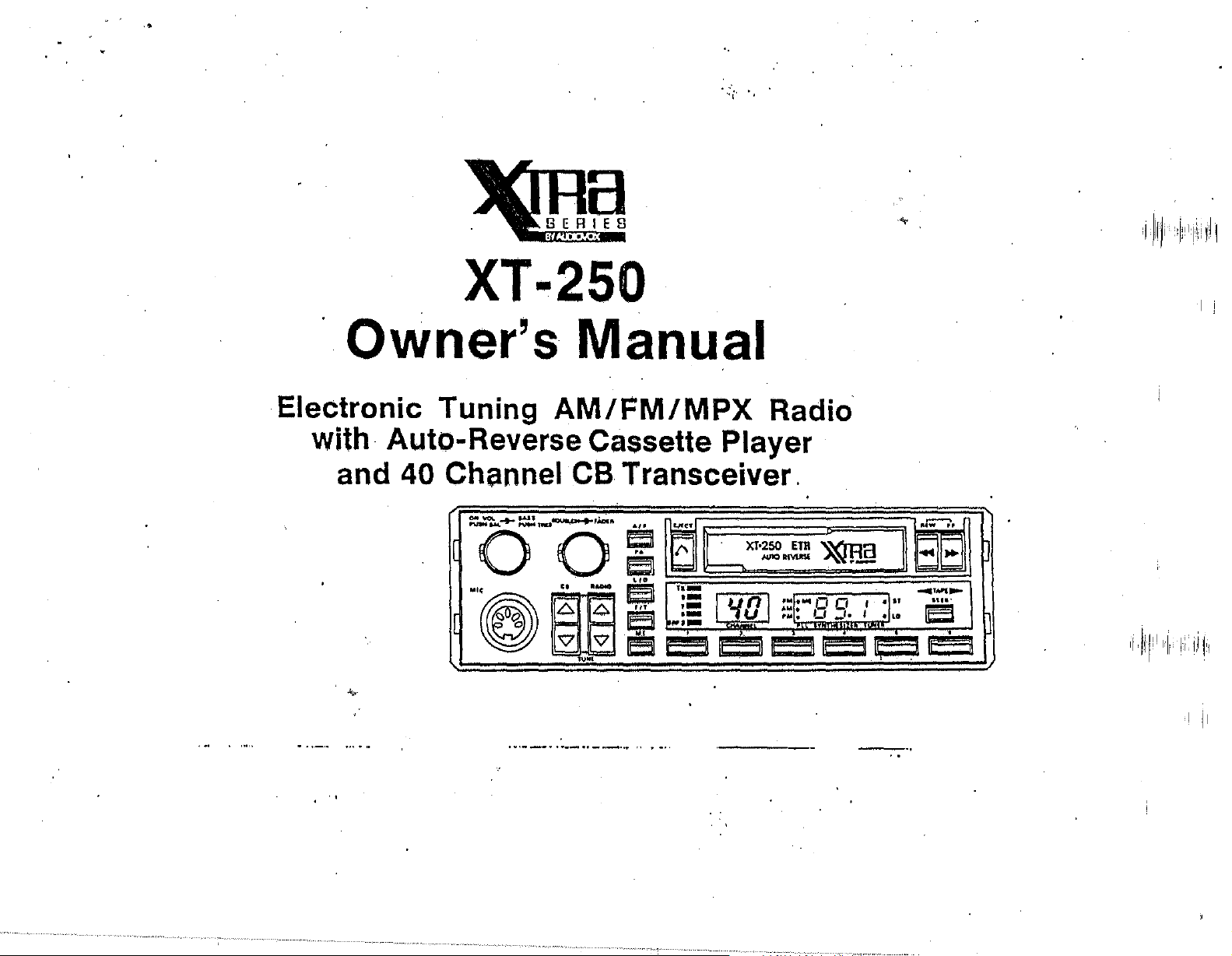
XT·250
Owner's Manual
Electronic Tuning
with· Auto-Reverse Cassette Player
and
40 Channel CB Transceiver.
~O-O'
.
"@g"·
~
AM/FM/MPX
~
'7",,"
g Z
" .
....
Ie'::1
~
e
Ii!!
CX1'~~
~l5
~
un
~ ~
~v
Radio
~jJ
'~I'''O
::1:
0 ,
LI
-" , .1..
1e1.~
~
~:
.•
,,,
-::::
Iel
15
I I
...
Page 2
)
1+.'
'AS
PUS
(2)
TRU
SO
ON
rUSH
VOl.
(1
.,A,
....
I[
()
--
MIC
§J
~I)
I~
Iwl
(
4)
UE\.C
+'1.0'"
.......
()
........
C.
TUN~
ftAOIO
L:::.
=
'\i7
(3) (5)
A ,
..
~
LID
e
Fr'
~
"
6
..
(6)
~
T
f\
=
,x_
,-
,-
.-
SRf3ijiiii
I
(7) (8)
XT·250
1"':01
c • L
,
AUTO
ETR
REVERSE
fM
.MI
AM
: O.D.
"M
il
~..§
If
•
,
:1,"
I
• LO
U\
TUNtR
I
il
If
II
..-L
.r;-
j;;;:
..
~
i== i==
......
TA.,.E·~
a.
II
,
,
,;;;
I!
(9)
(16)
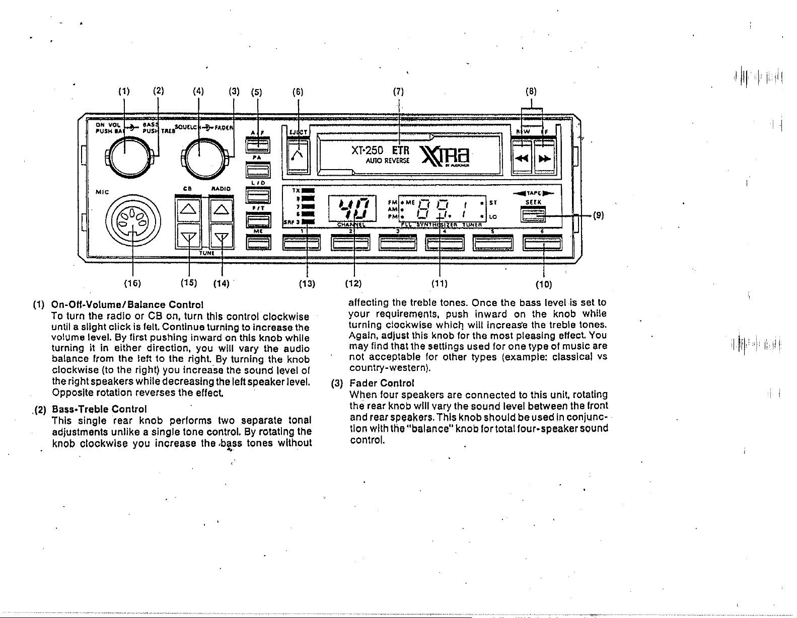
(1)
On-OH-Volume/Balance Control
To
turn the radio or CB on. turn this control clockwise
until a slight click is felt. Continue lurnlng
volume level. By firsl pushing Inward on Ihls knob while
II
In
turning
balance from the left to the right.
clockwise (to the right) you increase the sound level
the
right speakers while decreasing the left speaker level.
Opposite rotation reverses the effect.
(2)
Bass-Trllble Control
.
This single rear knob performs two separate tonal
adjustments unlike a single tone control. By rotating the
knob clockwise you increase the
eilher direction. you will vary the audio
(15) (14)
By
,b~ss
10
Increase Ihe
turning the knob
tones without
(13)
of
(12)
affecting the treble tones. Once the bass level is set to
your requirements. push inward on the knob while
turning clockwise
Again. adjust this knob for the most pleasing
may find that the setlings used for one type of music are
not acceptable for other types (example: classical
country-western).
(3)
Fader Control
When four speakers are connected to this unit. rotating
the rear knob will vary the sound level between the front
and rear speakers. This knob should be used
tion with the "balance" knob for total four-speaker sound
control.
(1
1)
which will increas'e the treble tones.
(10)
eHect.
In
conjunc-
You
vs
i I
Page 3

(4)
Squelch Control
This knob
incoming
"break-through"
listened
be
received (Including background carrier noise
Is
to
be
used
to
determine how strong
CB
transmission must
be
to
automatically
the radio or tape program being
to.
At
low squelch settings almost all signals will
occasions). Higher settings require a stronger Incoming
to
signal
necessary
control has
break through. Some experimentation will
to
find a suitable compromise. The squelch
no
effect on outgoing
CB
transmissions.
Rotating' the control lully counter-ckockwise
"click"
Is
felt will completely turn
011
the
CB
and
display.
(5)
'PA
Selector
The built-In
loudspeaker paging amplifier. First,
horn type speaker must
the rear of the unit.
releasing the
the
PA
CB
mode.
amplilier of this unit can also
be
connected
Once this
PA
button on the unit will set the amplifier
By
depressing the talk switch
Is
done, depressing and
an
to
the
be
external
"PA"
on
held microphone and speaking Into the microphone,
your voice will be amplified and broadcast out the
speaker. Whenever the unit is in the
ch,lnnel display will
depress and release the
AlF
(AM-FM) Selector .
The selection
band
Is
of
made by depressing this button then releasing
The selected band will
Illuminating a dot next
LI
D (Local-Distant·) Selector ,
be
blank. To end
PA
button.
either the AM radio band or the
be
displayed on the
to
the
AM
PA
mode, the
PA
operation, re-
LED
or FM markings.
This control functions In radio and"'CB operation. In
an
on
be
unlll a
the
CB
used
as
PA
or
jack on
to
the hand-
PA
CB
FM
radio
panel by
a
It.
essence,
and
can be received. When the bullon
It
will
next to the
.
"Distant"
achieved. The setting of this
automatic
ing the amount of radio stations the system will
It
reduces the reception capability of the radio
CB In the "Local" mode
be
indicated by Illuminating a dot on
"LO"
symbol. Whenever the
so
mode, maximum reception capability Is
bullon
"Seek" tuning operation by limiting
that only strong signals
Is In the
"local"
the
switch
will also
mode,
LED"panel
Is In
effect
or
Increas-
"seek"
in radio mode.
IT
(Frequency-Time) Selector
F
In
normal use, the
Should you want
LED
panel will display the time of day.
to
see the radio Irequency displayed
depress and release this button. The radio frequency will
appear
for
approximately eight seconds then return
time display, The bulton can also be used to change the
10
radio frequency display back
tq
not want
wall for the eight second delay.
time display should you
The radio frequency will also be displayed temporarily
using any of the radio function controls (Up-Down
while
Tuning;
Seek; Station Pre-Set; F I A SelecUon and LID
Selection). Approximatley eight seconds after the control
is last used, the frequency display will change
tim.e
display.
ME
(Memory Enable) Pushbutton
This button
Is
used for several functions. See "Setting the
back
Clock" and "Stallon Preset Selectors".
the
the
10
I I
10
! I
Page 4

·
(6)
C tt
asse e Eject
Once
II
cassette
elect the cassette
cassette' will
removed from the tape
unit with the power off.
unit automatically reverts
(7)
Auto-Reverse Casselle Opening
The casselle mechanism
automatically retracts when a casselle
"load"
the cassette, verify the open tape side of the
cartridge
Into the opening until resistance
is
facing
Is
playing, you can stop the playing and
by
firmly depressing this button. The
be
partly released and can
sial
Do
not leave a casselle In the
Once the casselle
to
radio operation.
is
protected by a door that
to
the right and slowly guide the tape
Is
feit, A firm push on the
Is
ejected, the
Is
Inserted. To
tape will activate the loading mechanlsin and the tape will
be
drawn into the unit and begin playing. Play will
continue until you eject the cassette.
Once the end of the
tape is reached, the system reverses automatically and
begins to play the other
keep repealing until the casselle
(8)
Cas$elle Rewind-Fast Forward and Program Selector
side of the tape. This cycle will
is
ejected.
The two indicated buttons perform three separate
tions. Depressing the "REW" button will rewind the tape
at rapid speed until the
Depressing the
"FF" button will advance the tape at rapid
speed until the
"REW"
"FF"
button
but~on
Is
lightly pressed.
is lightly pressed,
Depressing both buttons at the same time will change
tape sides (if side 1 is being played it will change
2).
Since this
mec;hanlsm, you will find the function's
"FF"
buttons are always the same no matter which side of
the cassette is being played.
unit
has a special !oglc controlied
ef the "REW" and
Addltion~IIY,
be
easily
func-
to
side
located just
above the
"Seek" button you will find two illuminated
arrows which show which direction the tape is moving in
at
a glance.
(9)
Electronic Seek Tuning
The
next available radio broadcast station can
located when listening
releasing this button. The
to
one stalion
"seek"
by
butlonwill
be
depressing and
matically seek the next higher station and stop. The
setting of the Local-Distant switch will greatly affect the
01
use
function
station
this bullon.
willskip
broadCast. In the "DISTANT" mode,
the very first station it comes
almost out of range. The seek mode
stopped when
manually
(10) Stalion Preset Selectors .
by
re-depressing the button.
In
the "LOCAL" mode, the seek
over weak stations until
to
even if it
It
finds a station or
It
finds a strong
It
will stop at
Is
is
automaticatlY
you
can cancel it
weak and
Six soft-touch pushbutton' selectors have been provided
to
enable you \0 memorize up
stations
these seiectors, refer
a.
b.
(6
AM
stalions and 6
to
the following:
Turn on radio, Select either
Select the first radio station
!lither the "Up-Down" tuning selectors or the
using
to
twelve different radio
FM
stations). To program
AM
or
FM
band,
to
be
programmed by
"Seek" tuning.
c.
Depress the
illuminate near the ME marking
"ME"
button and you will see
on
the displayfor
8 seconds.
d.
You must depress the first
within the 8 seconds, At this time the
of
the six memory pre-sels
LED
will go out
quiCkly
auto-
an
LED
I I
Page 5

· and the lirst radio station
pre-set button.
e.
Repeat
change
buttons for six additional stations on the other band.
b,
c and d for
to
the
other band and re-program
is
plOgrallll1led
the
remaining five pre-sets then
(11) Radio & Function Display Panel
This
LED
panel provides a visual display of all radio
functions. First it shows which radio frequency
selected
ly
by
you know which band is selected (the AM also functions
with
indicates a
Indicates
Selector). Other
Memory Enable button
panel will indicate
quency
(12)
CB
When
indicate which
selec.ted,
blank.
SRF
(13)
In
illuminate
LED's will Indicate relative modulation level,
by
displaying the numerical frequency. Second-
illuminating a small dot near the AM or FM marking
PM
for time display). Additionally, the
"Stereo" broadcast while
the
"Local" mode
indications Include
is
not displayed.
Channel DIsplay
In
CB
operation, this display will illuminate and
of
the
If
"PA" mode
is
selected (see Local-Dlstllnt
Is
selected. Finally, the display
the
Time whenever the radio fre-
40 available CB channels has been
Is
selected, the display will
"ST"
tti~
"LO" marking
"ME"
ITX Meter , '
the transmit mode of
to
verify signal transmission while the
CB
operatio'n, the "TX"
...
on
tile lirst
the
six
marking
to show the
.I
LED
will
SRF
In
the
Is
be'
receive mode, the LED's indicate sequentially the
strength
Electronic Radio
(14)
To select a radio station, depress either the upward or
downward pointing arrow after
display panel, A quick depress and release will
(or decrease) the frequency one step while holding the
button in will rapidly advance the digits. Nota: AM radio
stations advance
etc.)
lor radio broadcast stations.
in
same reason, Nole: For
advertise their call sign
WWDH
104,0
a problem
on an even digit frequency.
stations' call frequency, you
or 1 04,1. They have :'rounded Itout"
purposes only. This was not a problem
radios
h<ld
rock It back and forth
electronic tuners are
the exact true frequency. Fortunately, most radio stations
realize the confusion they are causing and have begun
broadcasting their
01
the
incoming signal.
Station Tuning Selectors
observing.. the radio
In
10
KHz
steps
(530
...
540
as
this
is
the mandatory spacing required
FM
radio stations advance
.2
MHz steps (103.5
104
FM)
FM.
Only 103,9 or 104.1 can be selected. This
of
the radio since no
only
had a radio dlat with a moving pOlnter,AII you
to
do was move the pointer near "104" on the dlat and
...
103,7
...
103.9
..
simplfcity, some
as
an
even number (example:
and you will find you cannol tune to
FM
If you listen for
wUJ.flnd
to
"find"
far
more precise and willloC<lte only
"true" frequency.
FM
station can broadcast
It will
be,
to
104 for advertising
In
the past when
the station. 'Today's
Increase
...
550
by
the
FCC
'.
etc.) for the
sta'tions will
Is
th,e
"true"
either 1 03,9
...
not
IIII
,
,I
!'
"
I
''''III
I"~"~!
,
i i
Page 6

•
1'1
,'(15) Electronic
Thetwosoll-touch
ct,annel selection.
channel
channel you want
CB
Channel Setectors
bullons allow quick and accurate
to
Is
displayed on the
Is
wllh the upward pointing arrow.
a lower number. depress
Each lime the selected bullon
released. the channels
bullon
Is
depressed and held In, Ihe channels will
advance rapidly
(16)
Microphone Jack
To connect the
socket using care
CB
to
Seltlng the Clock
The clock can be set
1.
Turn
unit
on and depress
lime.
(if lrequency
2.
Depress and hold In the
3.
Keeping the
"ME"
Radio Up tuning button
Down bullon
and
"PM"
4.
Advancing the minutes past "59"
10
Indicators:
advance the hours.
use
the
bullons first observe which
CB
Channel Display. If
a higher number; press the button
If the desired channel
the
downward pointing arrow.
Is
briefly depressed and
will advance one digit. If
microphone, Insert plug into this
align the keyway and lighten the
by
the following method;
FIT
Is
displayed).
"ME"
bullon
bullon.
to
display the
nut.
bullon depressed, depress the
to
adv,lOce minutes and
advance hours. Also note Ihe
to
"00" does not
"AM"
CS
the
is
the
the
Addllional Operation
1.
CS
Microphone
Notes
-To
talk Into the microphonll, hold It
about61nches from your mouth and speak clearly
you
to
normal voice level. For
depress
switch
on
the
the
while you speak. Release it
transmit, you must
side of the mic'Pphone
In
o,rder
to hear the're
sponse.
2.
CB
Anlenna -Never allemptto use the
proper
on lhe rear
connecled
CS
antenna connected
of
the
unit. A standard radio antenna
to
the radio's antenna
able. Consult wllh your deafer for
to
the CB antenna jack
the
jack
Is
best type
CB
withoul a
not accept-
of
Trl-Band antenna for your vehicle.
Cold &
3.
cold.
abla
Heal-
Never use the casselte mode In extreme
Allow unit and casselle to warm up to a comfort-
level lirst. Avoid exposing casselles to extreme
heat or direct sunlight.
4.
Casselles - Defective, broken, warped or otherwise
damaged
minute) tapes should nol
cass~\le
caSselles must never
be
be
used
player. Use 0-30, C-60'or
used.
0-120
In
any automotive
0-90
only. Also see
cold and heat warning. '
.
In
a
CB or
(120
II
Made
In
Korea
Audiovox Corp., Hauppauage.
N.Y.
11788
r !
 Loading...