

Page 1
1000W (4/8 ohm and 70V) DSP SUBWOOFER AMPLIFIER
USER MANUAL
V1.8
Page 2
IMPORTANT SAFETY INSTRUCTIONS
1. Read these instructions.
2. Keep these instructions.
3. Heed all warnings.
4. Follow all instructions.
5. Do not use this apparatus near water.
6. Clean only with a damp cloth.
7. Do not block any ventilation openings. Install in accordance with the manufacturer’s instructions.
8. Do not install near any heat sources such as radiators, heat registers, stoves, or other apparatus (including
amplifiers) that produce heat.
9. Do not defeat the safety purpose of the polarized or grounding-type plug. A polarized plug has two blades
with one wider than the other. A grounding-type plug has two blades and a third grounding prong. The wide
blade or the third prong are provided for your safety. If the provided plug does not fit into your outlet, consult
an electrician for replacement of the obsolete outlet.
10. Protect the power cord from being walked on or pinched particularly at plugs, convenience receptacles, and
the point where they exit from the apparatus.
11. Only use attachments/accessories specified by the manufacturer.
12. Use only with the cart, stand, tripod, bracket, or table specified by the manufacturer, or sold with the
apparatus. When a cart is used, use caution when moving the cart/apparatus combination to avoid injury from
tip-over.
13. Unplug this apparatus during lightning storms or when unused for long periods of time.
14. Refer all servicing to qualified service personnel. Servicing is required when the apparatus has been damaged
in any way, such as power-supply cord or plug is damaged, liquid has been spilled or objects have fallen into
the apparatus, the apparatus has been exposed to rain or moisture, does not operate normally, or has been
dropped.
15. The apparatus shall not be exposed to dripping or splashing and that no objects filled with liquids, such as
vases, shall be placed on the apparatus.
16. WARNING: To reduce the risk of fire or electric shock, do not expose this apparatus to rain or moisture.
17. Where the mains plug or an appliance coupler is used as the disconnect device, the disconnect device shall
remain readily operable.
18. WARNING: The Class I apparatus shall be connected to a mains socket outlet with a protective earthing
connection.
APPLICABLE FOR USA CANADA OR WHERE APPROVED FOR USAGE
CAUTION: TO PREVENT ELECTRIC SHOCK MATCH WIDE BLADE PLUG TO WIDE SLOT INSERT FULLY.
ATTENTION: POUR EVITER LES CHOCS ELECTRIQUES INTRODUIRE LA LAME LA PLUS LARGE DE LA
FICHE DANS LA BORNE CORRESPONDANTE DE LA PRISE ET POUSSER JUSQU AU FOND.
Page 2
Page 3
INTRODUCTION
The James M1000 is a high performance, class D, subwoofer amplifier capable of delivering a minimum of
1000W of clean power at 4 ohms. It uses advance DSP technology to allow sophisticated optimization of the
amplifier’s parameters to match the subwoofer being used and the environment in which the subwoofer is
installed. The M1000 features a large LCD display and 5 button controller to allow configuration of all DSP
settings. On the front panel there are black-out indicators for power, standby, clipping and signal presence.
Upon startup, the display will show the firmware revision number.
James subwoofer installation.
The M1000 is a natural choice for every
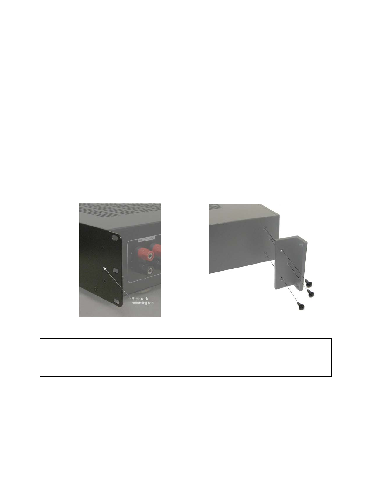
INSTALLING RACK MOUNT EARS
If you plan to install your M1000 into a standard 19-inch rack, you must install the supplied rack ears.
(1) Remove the 6 screws from the sides n ear the front of the M1000 (3 on each side).
(2) Using the same screws, attached the supplied rack ear s to the M1000. If required, the 4 feet can also be
removed at this time by unscrewing the feet mounting screws located in the center of each foot.
(3) Due to the weight of the M1000, it is recommended th at the rear flanges be secured to the rear rack rails.
Hardware to do this is not supplied with the amplifier and is specific to the type and depth of rack you are
using. You are responsible to source the proper hardware to secure the rear mounting points.
Rear Rack Mounting Tab Installing Front Rack Ears
CAUTION!
The M1000 amplifier is convection cooled and does not use a fan to eliminate noise and allow it to be
used in the listening environment. For this reason, ensure there is adequate ventilation above and below
the amplifier when rack mounted. Avoid placing heat generating equipment below it in the rack. If the
M1000 does not receive enough ventilation, if may overheat and switch to standby mode.
AC LINE VOLTAGE
The M1000 can be used on 110V-120V, 60Hz or 220v-240V, 50Hz AC lines. To change the operating line
voltage:
(1) Turn the power off using the rear power switch.
(2) If required, remove the IEC line cord and replace wi th an IEC AC cable that matches the AC wall socket.
NOTE: This should be a 10A rated cable.
Page 3
Page 4
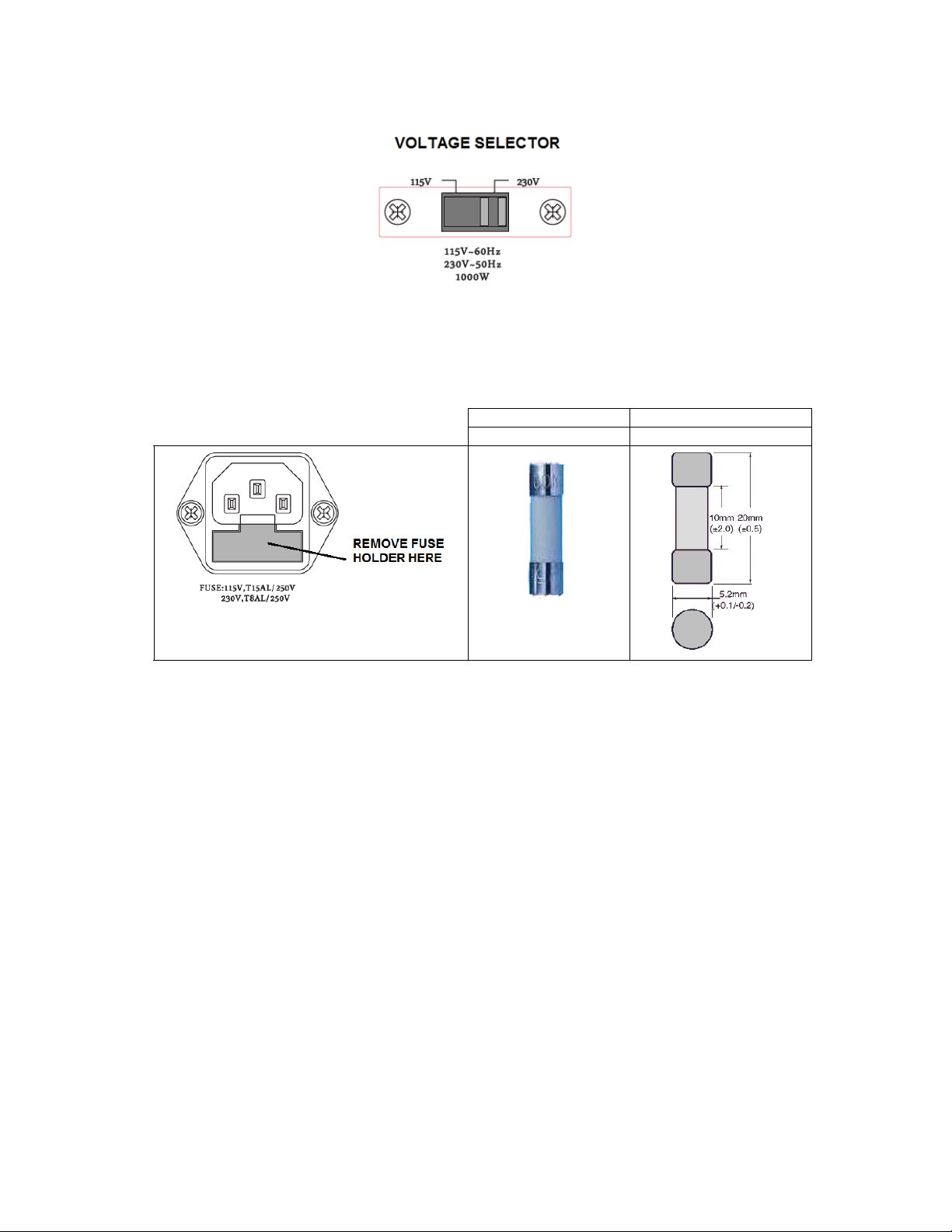
(3) Remove the plastic cover screws and the plastic cover over the 115/230V selector located on the rear of the
amp. Set the switch to the correct position for the line voltage in your country. Check the fuse and install
the correct value if needed.
(4) Replace the plastic cover and screws over the voltage selector switch.
(5) The M1000 is fuse protected and if you change the AC voltage settlings, you also need to change the fuse
to the correct value. Use only GDA type fuses. Values are listed below
115V OPERATION GDA TYPE 15A 250V
230V OPERATION GDA TYPE 8A 250V
NOTE: A spare fuses is also located in this
holder
INSTALLATION - CONNECTIONS
(1) Attach the audio input cable from your source to the proper input connector(s) on the M1000. Use the high
level binding posts if feeding a speaker level signal from the output of an audio amplifier. Use the XLR line
level inputs if you have a balanced audio signal coming from your receiver or processor. Use the RCA line
level input jacks if using an unbalanced line level source. If feeding the signal from the LFE output from a
home theater receiver or processor, you only need to use one cable and connect to either the left or right
input since the LFE signal is mono.
(2) Connect one end of the speaker wire to the speaker output binding posts observing the polarity and connect
the other end to the subwoofer terminals.
NOTE: All 5-way binding posts have an insulating plug inserted into the end of the post. If you wish to
insert a banana plug as your method of connection, you can insert the banana plug into the wire hole in the
binding post, or you can remove the insulators by popping them out with a small screwdriver.
Page 4
Page 5
Removing the binding post insulators Inserting banana plugs into wire holes
(3) If you haven’t done so, verify that the amplifier’s AC ma ins selector on the rear of the M1000 is set to your
AC line voltage and you have the correct fuse installed.
(4) Verify that the rear power switch is in the off posit ion. Plug the power cord into the rear IEC connector on
the rear of the amplifier. Connect the other end of the AC cord to an AC power wall socket.
(5) Once all the input, output and power cables are connected, turn the unit on and proceed with the DSP
setup.
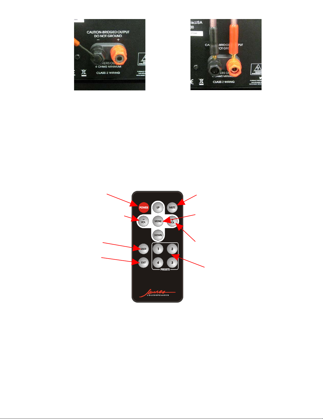
REMOTE CONTROL
Power on/off
Volume down
(DSP left-right when Menu button pressed)
Select “User” EQ setting
Exit navigation mode
The remote control duplicates the functions of the 5 button controller on the front of the M1000, plus adds some
additional functions such as power on/off, mute on/off, and 1 button selection of the 5 EQs. In a typical home
theater installation however, the remote will most likely NOT be used as the M1000 will be configured to a specific
subwoofer and room placement, and controlled by the main processor or receiver.
Mute button
Menu button - switches five button
cluster to act like the 5 button
navigation on the front of the
amplifier.
Volume up
(DSP left-right when Menu button pressed)
Select EQ Presets 1 through 4
IR CODES
For a complete set of codes, please go to our website at www.Jamesloudspeaker.com and download from the
M1000 page listed under Products > Electronics > Amplifiers > M1000 Sub-Amp.
Page 5
Page 6
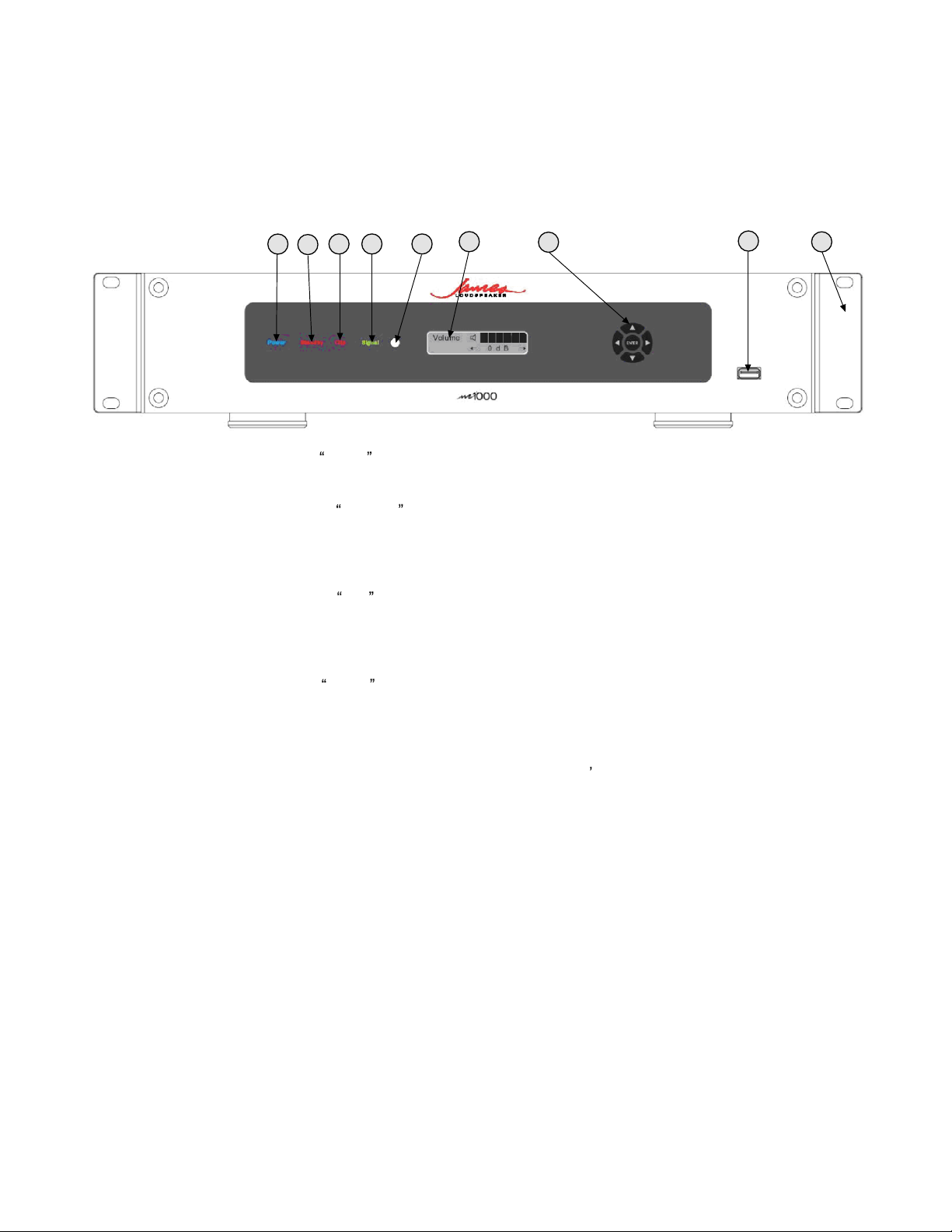
FRONT PANEL
1
364 5
2
7
8
9
1 Power Indicator - The word power will appear in blue when the unit is powered on and is out of standby
mode.
2 Standby Indicator - The word Standby will appear in red when the M1000 is in standby mode. The
M1000 is put into Standby Mode by turning the amplifier off through either the remote, the auto off mode or the
12V trigger. Also, if the amplifier overheats, the standby indicator will come on as the amplifier will go into
standby mode.
3 Clipping Indicator - The word Clip will flash in red when the power output exceeds the 1000W power
rating of the amplifier. Although running the M1000 into clipping is not recommend for sonic and woofer
reliability reasons, occasional clipping is generally acceptable on music and movie sources due to their very
dynamic nature. However, if any distortion is heard the amplifier level should be reduced.
4 Signal Indicator - The word Signal will flash in green when a signal is present on the inputs.
5 IR sensor/receiver - IR signals from the remote control are received here. If a IR sensor is plugged into the
rear IR input jack, this sensor will be turned off.
6 16 character x 2 row Liquid Crystal Display - Shows the amplifier s status, menus and settings and works
in conjunction with the 5 button navigation controls and the remote control.
7 5 button programming navigation controls - Used to scroll through the Display menus, change settings
and program the DSP controller.
8 USB Connector - For uploading new firmware/software.
9 Optional rack ears - Two rack mount ears for 19-inch rack mounting are provided for rack mounting. The
rear mounting holes should also be used for supporting the amplifier in a rack cabinet.
Page 6
Page 7

REAR PANEL
10
11
17
18
13
12
14 15 16
21
19
20
10 Left/right high level inputs - for connecting high level speaker outputs from another amplifier to drive the
subwoofer amplifier. Useful for zones where only stereo left/right high level speaker signals are available and a
subwoofer needs to be added.
11 Left/right RCA inputs - For feeding line-level stereo left/right signals. Also, either left or right RCA jack can
be used for a mono LFE input.
12 Left/right XLR balanced inputs - For feeding BALANCED line-level stereo left/right signals. Also, either left
or right XLR jack can be used for a mono LFE input.
13 Left/right RCA outputs - For looping the subwoofer input signal to additional amplifiers. The signal
received by the RCA or XLR inputs is passed out through these jacks and is not effected by the amplifier and
maintains left/right separation. XLR BALANCED inputs are converted to unbalanced RCA output.
14 12V trigger input (3.5mm) - For triggering the power on/off from other devices such as processors or
receivers that have a 12V trigger output. 6V minimum required for triggering.
NOTE: Once in trigger mode, the amplifier cannot be turned on without a 12V trigger signal. To disable the 12V
trigger, turn the unit off, then hold down the left and right navigation buttons while turning the amplifier on with
the rear power switch. The trigger mode will be turned off and the amplifier will power on.
15 External IR input (3.5mm) - For attaching an external IR receiver. Plugging in an IR receiver here will
disable the font panel IR receiver.
16 Speaker 5-way binding posts - Connect your loudspeaker here. Minimum impedance of the load is 4
ohms. Multiple woofers can be connected if the combined load impedance is 4 ohms or greater.
17 Power Switch - Turns the amplifier on or off. Amplifier must be on for the trigger or auto sense modes to
operate.
18 115V/230V AC mains voltage selector - For switching the operation for 110V-120V, 60Hz or 220V-240V,
50Hz AC line voltages. NOTE: when the AC line voltage is changed, the fuse must also be changed to
continue to provide protection to the amplifier.
19 IEC Power cable connector - Connect a IEC AC cable here rated for 15A service.
20 Fuse holder - The fuse holder is part of the IEC connector. Use a GDA type fuse as follows: 15A for 115V
operation and 8A for 230V operation.
21 Removable feet - The amplifier feet can be removed as required for rack mount installation.
Page 7
Page 8

LCD DISPLAY SCREENS/FUNCTIONS
Normally, the LCD display will show the status for a number of DSP settings as well as the volume level and a
flashing output level bar display. The “normal” display is show below.
Unmuted
EQ Setting
SUB or LFE mode
“Auto Off” Function ON
“Lock” Function ON
“External Trigger” ON
“Limiter” ON
Muted
Volume Level Setting
Output level meter
Navigation through the DSP menus and DSP settings are done via the 5 button controller on the front of the M1000
and the 5 button array on the remote control.
Once a limiter setting of anything but “0” is set, the red clip indicator on the front panel, which normally indicates full
power clipping, will now light when the limiter maximum power is reached. Also, an up arrow icon will appear on the
bottom row of the display to indicate the limiter is turned on.
M1000 Navigation Buttons
When in the Normal mode, pressing the left/right buttons will allow volume
Remote Navigation Buttons
adjustment and the display will change to
volume mode (see below).
Pressing the “enter” button will switch to the DSP setting mode and the first screen to appear will be the “Subsonic
Freq” display. From that point, the “up” and “down” buttons will scroll through the different setting screens as listed
below. The left and right buttons will allow you to set the options for any screen. If you acci
dently get to a screen you
wish to exit, do not press a button for 3 seconds and display will revert back to the “normal” mode. You can also
select the default setting again.
On each DSP display screen, the current DSP default setting will be displayed. If you use the left/right buttons to
select a new option for that setting, you must them press “menu” to select this option.
When scrolling left/right through
the options, the current default will have an asterisk next to it.
Once you have configured all the settings for your product, you can save them as 1 configuration by using the
“Memory Store” screen. In this way, if the settings are
invariantly changed, you can always recall your saved settings
in this way. NOTE: Avoid storing to the Memory 3 location as this is where James stores the configuration for your
subwoofer if it was programmed at the factory.
If James has configured your M1000 for a specific subwoofer, it will be saved in Memory 3 location. This can be
overwritten so avoid saving any settings to the memory 3 location unless advised by James personal.
You can always revert to the factory default settings by recalling “default” in the “Memory recall” function.
Following are further explanations of each DSP screen. Also, a flow chart follows this section with further details.
Page 8
Page 9

Normal Screen
This is the normal operating screen for the DSP and some of
the current settings are displayed along with a volume bar and
an output level bar meter. (see details above).
NOTE: Pressing the Menu button will take you to the first DSP
setting, “Subsonic Frequency”. Pressing the left/right buttons
1 2 3 4 5 6 7 8
will take you to the “Volume” Ssetting screen. The output display
can be used to estimate the approximate power output during
operation.
Segment Volts 8ohm Watts 4ohm Watts
Top of segment 8
63 500 1000
Top of segment 7 40 200 400
Top of segment 6 15.5 30 60
Top of segment 5 6.3 5 10
Top of segment 4 2.5 1.5 1.5
Top of segment 3 1.0 0.125 0.25
Top of segment 2 0.4 0.02 0.04
Top of segment 1 0.16 0.0035 0.007
Volume Control
The “Volume” control is available from the “Normal” screen
and is activated by pressing the left/right pushbuttons. This
feature allows you to adjust the output volume of your
subwoofer amplifier and ultimately, the output of your
subwoofer. The volume should be set to achieve the best
balance between the main speakers and the subwoofer. After 5
seconds, display will revert back to Normal.
Use “left” and “right” push buttons to set.
Subsonic Freq
Mode Select
Crossover Freq
The “Subsonic Freq” setting allows you to limit the low
frequency range of the sub and is generally used to protect
subwoofers from over-excursion and/or damage from operating
below the subwoofer’s tuning frequency. A “flat” setting is
provided to remove the fliter, or a filter frequency can be set
from 16Hz to 40Hz in 1 Hz steps.
Use “left” and “right” push buttons to set and “menu” to save.
The “Mode Select” allows switching the amplifier between
LFE or SUB mode. In LFE mode, the crossover slope and
frequency adjustments are disabled. The crossover frequency
should then be set by an external processor/receiver.
Use “left” and “right” push buttons to set and “menu” to save.
ONLY AVAILABLE WHEN IN SUB MODE.
The “Crossover Freq” setting allows the crossover frequency
to be set from 40 to 160 Hz in 1 Hz increments. For reference,
the crossover slope is displayed in the upper right hand corner.
Use “left” and “right” push buttons to set and “menu” to save.
Page 9
Page 10

Crossover Slope
EQ Mode
User EQ Setup
ONLY AVAILABLE WHEN IN SUB MODE.
This “Crossover Slope” setting allows the crossover slope to
be set from 6 dB/octave 36 dB/octave in 6 dB/octave
increments. The higher the slope, the less mid-band
information will get through to the subwoofer, but there will be
greater phase change which might effect the sound of the
system as a whole.
For reference, the crossover frequency is displayed in the
upper right hand corner.
Use “left” and “right” push buttons to set and “menu” to save.
The “EQ mode” setting allows six selections
- “Flat” removes any EQ and provides flat frequency response.
- “User” setting allows the user to adjust and program a
personal EQ curve.
- The 4 presets (EQ1 to EQ4) are factory presets and should
only be used when instructed by the factory.
NOTE: James may rename any Preset EQ to a specific James
Model of subwoofer.
Use “left” and “right” push buttons to set and “menu” to save.
ONLY AVAILABLE WHEN IN USER MODE.
In “User EQ” mode, the user can adjust and program nine 1/3
octave bands from 20 Hz to 125 Hz. (20, 25, 31, 40, 50, 63,
80,100,125 Hz) by using the left/right pushbuttons. At each
frequency, there is a +6 to -6 dB level adjustment in 0.5 dB
steps and can be adjusted by pressing the up/down
pushbuttons. This feature duplicates a typical third-octave
equalizer as show below.
Phase Setting Select
The “Phase” setting is used to adjust the phase/polarity of the
subwoofer to provide the best summing to the main speakers.
The physical placement and distance of the subwoofer in
relation to the main speakers may result in unwanted
cancelation of some of the bass and can be compensated for
by adjusting the phase setting.
The phase setting can be adjusted while listening for maximum
or best bass performance or by using a real time analyzer and
measuring the actual response of the system as a whole.
The phase adjustment is in 45 degree steps from 0 to 315
degrees.
Use “left” and “right” push buttons to set and “menu” to save.
Page 10
Page 11

Limiter
The limiter function allows setting the maximum power which will
be supplied by the M1000. This is useful for preventing overpowering smaller subwoofers. Like most audio amplifiers, the
M1000 is a voltage amplifier and delivers voltage to the load.
But the actual power depends on the impedance of the load, so
the limiter is set by -dB, which are independent of actual power
but indicate level reductions. The load on the M1000 can be 1 or
Limiter On
Limiter setting (dB) % of max 8ohm Watts 4ohm Watts
2 subwoofers, as long as the total impedance remains 4 ohms
or higher. The limiter is set in -dB, which is the dB from full power
which at 4 ohms, is 1000 watts, but only 500 watts at 8 ohms. A
-3dB reduction is half the power so 3dB changes are bolded in
the table since they are an easy reference point.
Once a limiter setting of anything but “0” is set, the limiter icon
appears on the display (see illustration) and the red clip indicator
on the front panel, which normally indicates full power clipping,
will now light when the limiter maximum power is reached.
0 100% 500 1000
-1dB 79% 397.2 794.3
-2dB 63% 315.5 631.0
-3dB 50% 205.6 501.2
-4dB 40% 199.1 398.1
-5dB 32% 158.1 316.2
-6dB 25% 125.6 251.2
-7dB 20% 99.8 199.5
-8dB 16% 79.2 158.5
-9dB 13% 62.9 125.9
-10dB 10% 50.0 100.0
-11dB 8% 39.7 79.4
-12dB 6% 31.5 63.1
Delay msec
D e l a
Delay Units
D e l a
Display Setting
y
y
u n i t s
*
1 0 .
*
m s e c .
m s e c .
0
The delay feature allows delaying the sub signal up to 30 msec
or approximately 30 ft. This is useful for aligning arrival times of
rear subwoofers with the front subwoofers. The “Delay msec”
feature displays the actual delay setting which will be in the
“units” as set in the previous menu item.
The delay feature allows delaying the sub signal up to 30 msec
or approximately 30 ft. This is useful for aligning arrival times of
rear subwoofers with the front subwoofers. The “Delay Units”
feature is set to msec, feet or meters, use whichever unit you
are most comfortable working in.
The “Display” setting has 2 options to control the LCD display
brightness, ON and 30 seconds. When set to “On”, the LCD
display is always illuminated. When set to 30 seconds, the
display back light will turn off after 30 seconds if no button is
pressed.
Use “left” and “right” push buttons to set and “menu” to save.
Page 11
Page 12

Auto Off Setting
External Trigger Select
The “Auto Off” setting allows the amplifier to turn on and off
based on the presence of an audio signal. When set to “off”,
the function is disabled and the amp stays on constantly. When
set to ON, the amplifier is controlled by the presence, or
absence, of audio signal on the input jacks. When an input
signal is present, the amplifier will turn on immediately. Once
the signal stops, the amplifier will turn off after the selected
time duration. There are duration settings from 5 minutes to 30
minutes in 5 minutes increments. Typically this is used with a
receiver which does not have a 12V trigger.
Use “left” and “right” push buttons to set and “menu” to save.
The “External Trigger” setting is used to allow an external
12V trigger source to turn the amplifier on and off with a 12V
trigger from another device, such as a processor or receiver.
NOTE: Once this feature is selected, the amp will stay in
standby mode until 12V is applied to the 12V trigger jack on the
rear of the amplifier. This means you cannot TURN OFF the
feature unless the amp is on and the amplifier can only be on
with a 12V trigger signal applied. However, it is possible to
bypass the need for the trigger signal and turn the amp on by
doing a special power-on sequence as follows:
(1) Turn the amp off,
(2) Push and hold the left and right pushbuttons on the
DSP navigation control,
(3) While holding the buttons turn the amplifier on with the
rear power switch.
The amp will power on with the external trigger turned off.
Use “left” and “right” push buttons to set and “menu” to save.
Lock Setting
Memory Store Function
Memory Recall Function
The lock setting allows the user to lock the DSP settings in
memory and prevent adjustment via the DSP pushbutton
controls. To lock, set to “Enable”. To turn off the lock, set to
“Disable”.
Use “left” and “right” push buttons to set and “menu” to save.
There are 3 independent memories which can be used to save
all the DSP settings as a single configuration. Once you have
finished programming all the features, select a memory location
(1, 2 or 3) and press Menu to save.
NOTE: memory 3 is used by James to store settings in some
cases so avoid using this location unless you are certain there
is no James setting saved there,
Use “left” and “right” push buttons to set and “menu” to save.
There are 4 memory locations that store 4 independent DSP
settings. Memories 1, 2 and 3 are programmed by the user
using the “Memory Store” function. A 4th setting, “Default”,
resets all the settings back to the factory default.
NOTE: Memory 3 is sometimes used by James to store
settings for a specific product.
Page 12
Page 13

MENU ITEM
Subsonic filter (Freq)
Subsonic filter (Slope)
EQ
Phase
Limiter
Delay Units
Delay
Display
Auto Off
Mode
Ext Trigger
Lock
Volume
DSP MENU TREE
START/NORMAL SCREEN
Default Settings
DEFAULT SETTING
20 Hz
24dB/octave
Flat
0 Degrees
0dB (off)
msec
0
On
15 Mins
SUB
Off
Off
-30dB
Navigation through the display menus is
Accomplished by the 5 button control pads on
Adjusts volume 0 to
-79 dB
the front panel of the M1000.
If LFE mode
If EQ-1 to EQ-4 or default
If SUB mode
If USER
Flat, User, EQ-1
EQ-2, EQ-3, EQ-4
Sets subsonic filter
from 16-40 Hz
Sets crossover
frequency
40-125 Hz
12 dB to 36 dB
Per octave
Select either Flat, USER EQ
which can be then adjusted by
the user, or 1 of 4 preset EQs
Set Freq
20 – 125 Hz
If no button is pressed for 3 seconds,
the display reverts back to “normal”.
Sets the crossover frequency
40-125 Hz (in SUB mode only)
Sets the slope of the crossover
(in SUB mode only)
Set Level
+/- 6 dB
Select the third octave band
and then adjust the boost/cut
0 to 315 Degrees
Set the Phase or best
summing to main speakers
Page 13
Page 14

L i m i t e r
0
. 0 d B
*
0dB to -12dB,
1 dB steps
D e l ayu n i t s
D e l a
*
y
*
m s e c .
m s e c .
1 0 .
Feet, meters,
msec
0
0-30ft (or meters or msec)
0.1 msec steps
Set the display to be
ON or 30 Sec
permanently on, or to turn off
after 30 secs of inactivity
Disable to 30 min
Turns signal sense auto off,
or on from 5 to 30 mins
To cancel “12V trigger mode” ‐ power the unit off
Sets mode to LFE (no
SUB or LFE
crossover) or SUB (turns on
crossover adjustment menus)
On or OFF
Sets 12V trigger mode on or
off. To cancel trigger mode
push and hold the left and right buttons while
On or OFF
Mem 1, Mem 2
Mem 3
Set lock mode on or off – on
prevents adjusts
Save all settings to 1 of 3
memory locations
turning the power on.
Mem 1, Mem 2
Mem 3, Default
Recalls saved settings from 1
of 4 memory locations
Page 14
Page 15

M1000: 1000W DSP SUBWOOFER 4/8 OHM and 70V AMPLIFIER SPECIFICATIONS
GENERAL FEATURES
- High Efficiency, Class D, 1000W RMS (4 ohms) output stage
- DSP signal control for precise adjustment and configuration of the audio signal
- 16x2 character LCD display
- 5 button user interface
- left/right XLR Balanced inputs, RCA unbalanced inputs, and high level binding post inputs for integration
into all systems
- 1 set 5-way binding posts for speaker output connection.
- left/right RCA unbalanced “loop-though” outputs for connecting additional amplifiers and electronics
- 12V trigger input
- 115/230V switchable power supply
- Lock-out mode to prevent accidental changes to settings
- Ability to save 3 separate set-up configurations to memory
DSP FEATURES
Volume: Adjustable, 0 to -79dB in 44 steps
Subsonic Filter: Adjustable 24dB/Octave 16-40 Hz, 1 Hz increments
Crossover Frequency: Adjustable 40-160Hz, 1 Hz increments
Crossover Slopes: Adjustable 12dB-36dB/octave, 6 dB increments
User EQ: 9 independent third-octave frequencies (20 Hz -125 Hz)
with +/-6dB range in 0.5 dB increments
4 factory Preset EQ settings: Application dependent
Limiter: Up to 12dB of power reduction in 1dB steps
Delay: Up to 30 msecs of delay (in selectable msecs, feet or meter units)
Phase: Adjustable 0-315 degrees, 45 degree increments
Mode: Sub (crossover) or LFE
Display Mode: display on, or off after 30 sends of inactivity
Memories: 3 configuration memories for settings.
SPECIFICATIONS
Nominal Power output (4 ohms): 1000WRMS <1% THD
Typical Power Output (4 ohms): 1080WRMS <1% THD
THD @1000W (4 ohms) 0.07%
THD @1W (4 ohms) 0.08%
Frequency Response
Sub mode: 10-160 Hz (subsonic and crossover adjustable)
LFE mode: 10- 2 kHz (Subsonic adjustable)
S/N ratio: 100dB Sub/ 90dB LFE
Output Noise: 1.5mV Sub/ 2mV LFE
Input Sensitivity (for 1000W out)
RCA In: 220 mV
XLR In: 220 mV
High Level In: 2.6V
Line out: 200mV (approx 0 dB gain)
Auto-on Sensitivity: 3.2 mV
Auto-off time: Adjustable 5 - 30 mins, 5 mins steps
12V trigger: 6V DC @ 2ma minimum required to trigger
Power Requirements: 115V/15A max or 230V/7.5V max
Standby Power: <0.5W
Dimensions (Height): 4” (101.5mm) with feet, 3.5” (89 mm) without feet
(Width): 19” (483 mm) with rack ears, 16.75” (425.5 mm) without rack rears
Net Weight: 26.5 lbs (12 kg)
Shipping Weight: 34 lbs (15.5 kg)
(Depth): 14.25” (368.5 mm)
Page 15
Page 16

APPENDIX A – PRESET EQ CURVES
To reprogram any Preset EQ, use the following settings
20 Hz 25 Hz 31 Hz 40 Hz 50 Hz 63 Hz 80 Hz 100 Hz 125 Hz
Preset 1 0 dB 1 dB 1 dB 1 dB 0 dB 0 dB 0 dB 0 dB 0 dB
Preset 2 0 dB 2 dB 2 dB 2 dB 0 dB 0 dB 0 dB 0 dB 0 dB
Preset 3 0 dB 2 dB 2 dB 1 dB 1 dB 0 dB 0 dB 0 dB 0 dB
Preset 4 0 dB 3 dB 3 dB 2 dB 2 dB 0 dB 0 dB 0 dB 0 dB
Page 16
Page 17

APPENDIX B – Thermal and Power Input Data
Voltage Watts Amps VA BTU'S Calories
WATT = 3.41 BTU
108 21 0.277 29.92 71.61 18060 WATT = 860 Calories
115 23 0.291 33.47 78.43 19780
120 24 0.297 35.64 81.84 20640
132 28 0.315 41.58 95.48 24080
Standby W 10.7 W
Serials BEFORE 1206xxxx
Standby W 0.5W
Serials starting with 1206xxxx and AFTER
Idle W 24 W
Line V 120 V
Line Freq 60 Hz
HEAT OUTPUT LEVELS
SINE WAVE LOAD W
@120V
AMPS
@240V
AMPS
VA BTU'S CAL
85 W (1/8 power) 8 ohm
115 1.47 0.735 176 VA 102.3 25800
225 W (1/3 power) 8 ohm
273 3.23 1.615 388 VA 163.7 41280
675 W (full power) 8 ohm
847 9.05 4.525 1086 VA 586.5 147920
128 W (1/8 power) 4 ohm
170 2.08 1.04 250 VA 143.2 36120
342 W (1/3 power) 4 ohm
432 4.87 2.435 584 VA 306.9 77400
1024 W (full power) 4 ohm
1406 14.92 7.46 1790 VA 1302.6 328520
THERMAL AND POWER INPUT DATA
INPUT POWER
Generally accepted power levels for thermal and power consumption calculations are 1/8W power input into the
expected subwoofer impedance. 1/8 power approximates usage with little or no clipping of the amplifier and
distortion free operation. 1/3 power equates to severe amp clipping and audible distortion.
WATTS OUT
IDLE POWER, NO SIGNAL INPUT
Page 17
Page 18

APPENDIX C – TROUBLESHOOTING
1) THE AMPLIFIER APPEARS TO HAVE NO POWER (NO LEDs COME ON)
There are a few obvious things to check. Make sure the amp is plugged in to an active AC power receptacle
and if it is a switched outlet, make sure the power is turned on. Make sure the rear power switch is turned on.
Once you have confirmed the AC power is turned on, make sure the voltage selector on the rear of the amp is
set correctly. Having the selector at 230V while plugged into an 115V outlet will keep the amp from turning
on.
Check the fuse located in the IEC power receptacle.
2) THE AMPLIFIER WILL NOT COME OUT OF STANDBY MODE
If the amp was configured to use the 12V trigger, if will only turn on when a 12V trigger signal is applied to the
12V trigger input. If you are not using a 12V trigger, then you can reset the 12V trigger to “off” by turning the
amplifier off, and then turning the amplifier on while holding down the left and right front panel navigation
buttons.
The amp could have overheated. Let the amp cool down.
The amp might have suffered an internal component failure. The amplifier will need to be serviced.
3) THE AMPLIFIER IS ON BUT THERE IS NO SOUND FROM THE SUBWOOFER
Check the front panel to see if the green “Signal” indicator is on or flashing. If so, this indicates a signal is
going into the amp. So the problem will be between the speaker output from the amp and the subwoofer,
most likely an open or shorted speaker wire, or a poor connection at either location, or a bad subwoofer.
Make sure the volume is turned up on the amplifier.
If the green signal indicator does not come on or flash, then there is no signal entering the amp and you
should check the cables running into the amp inputs and the source feeding the signal to the amplifier.
If the amplifier is on, but the red standby indicator is on, check the issues listed in item 2.
4) THE AMPLIFIER PRODUCES A BUZZ/HUM IN THE LOUDSPEAKER
Any buzzing or hum that does NOT change level with the volume control is generally caused by a ground loop
condition. This is especially common when the M1000 is located on a different AC line from the other
equipment or when all the electronics are rack mounted so the chassis’s are all grounded via the metal rack.
Though using a ground lift adapter on the amplifier’s AC plug may cure the buzz/hum issue, removing the
ground may result in an unsafe condition if the amp was to experience a power supply failure. We suggest
the use of a ground input isolator such as the Radio Shack “Ground Loop Isolator”, part number 270-054. An
input isolation transformer can also be used.
If the buzz/hum changes with the volume level, it can still be caused by a ground loop and this should be
checked. But also, the buzz/hum could be caused by a bad input cable, so a cable swap is recommended.
5) NO OUTPUT ON THE RCA LOOP THROUGH RCA JACKS
If you are feeding your signal into the XLR inputs, the initial production run of M1000’s did not feed the XLR
outputs to the RCA loop out jacks. So you will need to use the RCA inputs for these models. This applies to
any serial number starting with 0910.
6) AMP DOES NOT APPEAR TO GET LOUD ENOUGH YET THE CLIP LIGHT IS ON
Check to see if the limiter has been set to a low power level.
Page 18
Page 19

LIMITED WARRANTY
James Loudspeaker (“James”) warrants to the original retail purchaser (“Purchaser”) only that this James Product (the “Product”) is to be
free from defects in materials and workmanship for a period as listed below for each product category:
Indoor loudspeaker systems (excluding electronics) - (10) years
Outdoor loudspeaker systems (excluding electronics) - (3) years
Marine loudspeaker systems (excluding electronics) - (3) years
Subwoofers (excluding electronic components) – (5) years
All electronic components (amplifiers, DSP, remotes etc) – (2) years
Though James does not require a Proof of Purc hase be supplied with the returned Produc t, it is the Purchaser’s responsibility to have
available and, if requested by James, to provide a Proof of Pu rchase before warranty status is determined. If no Proof of Purc hase is
available when requested, James has the option of rejecting any and all warranty repair claims and/or requests for the Product.
If the Product model is no longer available and cannot be repaired e ffectively or replaced with an identical model, James, at its sole
discretion may replace the unit with a current model of equal or greater performance. In some cases, modification to the mounting surface
may be required where a new model is substituted. James assumes no responsibility or liability for such modification. James’s maximum
liability is limited to the repair or replacement of the Product only.
Any Product being returned to James for warra nty service must have a RMA# clearly mark ed on the outside of the shipping container.
Please call James prior to shipping the product to obtain an RMA#.
Freight collect shipments will be refused. The Product must be shipped in the original shipping container or its equivalent; in any case the
risk of loss or damage in transit is to be borne by the Purchaser - James recommends all shipments be properly insured. Product(s) replaced
or repaired under this Warranty will be returned, within a reas onable time, freight collect. However, for any Product that is deemed to be
under warranty and to have failed within 60 days from the date of purchase, James will pay nominal ground shipping charges both from
and to the Purchaser for locations within the contiguous United States.
Limitations:
• This limited warranty does not include service or parts to repa ir damage caused by improper installation, accident, misuse, abu se, neglect,
mishandling, commercial use, wear from ordinary use or environmental deterioration, inadequate packing or shipping procedures, voltage in
excess of the rated maximum of the unit, cosm etic appearance of cabinetry not directly attributable to defects in materials or workmanship, or
service, or repair or modification of the Product which has not been authorized by James.
• This limited warranty does not cover cosmetic damage, including paint damage, or consequential damage to other components or premises which
may result for any reason from the failure of the product.
• This limited warranty is null and void for products not used in accordance with James Loudspeaker’s instructions.
• This limited warranty is null and void for products not purchased from an authorized James dealer as appointed by James.
• This limited warranty terminates if you sell or otherwise transfer this product to another party.
• Determination of warranty status will be at the sole discretion and determination of James.
This Warranty is in lieu of all other expressed Warranties. If this Product is defective in material or workmanship as warrante d above, your sole remedy
shall be repair or replacement as provided above. In no event will James be liable to the Purchaser for any incidental or conse quential damages arising out
of the use or inability to use the Product, even if James has been advised of the possibility of such damages, or for any claim by any other party. Some states
do not allow the exclusion or limitation of consequential damages, so the above limitation may not apply.
All implied warranties on the Product are limited to the duration of this expressed Warranty. Some states do not allow limitati on on how long an implied
Warranty lasts, so the above limitations may not apply. This Wa rranty gives the purchaser specific legal rights, and the purcha ser also may have other
rights which vary from state to state.
JAMES LOUDSPEAKER LLC
535 Airpark Road
Napa, CA 94558
Phone: +1.707.265.6343 Fax: +1.707.265.6334
www.JamesLoudspeaker.com
V1.8
 Loading...