

Page 1
V-E-400
Emodumeter
Operator’s Manual
Original Instructions: Revision February 2017
Page 2

Page 3

Notice
The James Instruments Emodumeter ™ has been tested in accordance
with the EU regulations governing Electro-Magnetic compliance and it
meets required directives.
Emodumeter™ is a registered trademark of James Instruments Inc. and is
property of its respective owner.
© 2017 James Instruments Inc. All rights reserved.
No part of this publication may be reproduced, stored in a retrieval system,
or transmitted, in any form, or by any means, mechanical, electronic,
photocopying, recording, or otherwise, without prior written permission of
James Instruments.
No patent liability is assumed with respect to the use of the information
contained herein. Moreover, because James Instruments is constantly
striving to improve its high-quality products, the information contained in
this manual is subject to change without notice. Every precaution has been
taken in the preparation of this manual. Nevertheless, James Instruments
assumes no responsibility for errors or omissions. Neither is any liability
assumed for damages resulting from the use of the information contained
in this publication.
Page 4

Contents
Table of Contents
Introduction ....................................................................................... 1
Instrument Contents List .................................................................. 2
Contents List ............................................................................ 3
Testing Bench Contents List ............................................................ 4
Contents List ............................................................................ 4
Emodumeter Overview ..................................................................... 6
Control Panel Buttons.............................................................. 7
Menu Layout..................................................................................... 8
Emodumeter Run Mode ................................................................... 9
Emodumeter Setup Menus ............................................................ 10
Emodumeter Selections ................................................................. 11
Gain ....................................................................................... 11
Sampling rate and number of data points ............................. 11
Trigger Level .......................................................................... 12
Review Menu.................................................................................. 13
System Setup ................................................................................. 14
Changing Date ....................................................................... 14
Erase Memory ....................................................................... 16
Display Cursor ....................................................................... 17
Battery Operation .................................................................. 18
Battery Charge ...................................................................... 19
Simple Guidelines for Battery Maintenance .......................... 20
Upload Menu .................................................................................. 21
Test Bench ..................................................................................... 22
Accelerometer ................................................................................ 23
Testing Procedure .......................................................................... 25
Longitudinal Frequency Mode ............................................... 25
Transverse Frequency Mode ................................................ 29
Torsional Frequency Mode .................................................... 32
Emodulinx Introduction ................................................................... 35
Features ................................................................................ 35
Minimum System Requirements ........................................... 35
Emodulinx Overview ...................................................................... 36
Menu Descriptions ................................................................. 37
Software Installation ....................................................................... 38
iv www.ndtjames.com
Page 5

Contents
Connecting the Emodumeter ......................................................... 43
Overview of Menus ........................................................................ 44
Setup Menu ........................................................................... 44
Selection Menu ...................................................................... 46
Review Menu ......................................................................... 47
Upload Menu ......................................................................... 48
FFT Menu .............................................................................. 50
Tips and Troubleshooting ............................................................... 51
Sampling Frequency and frequency resolution ..................... 51
Contact accelerometer .......................................................... 51
Trigger level ........................................................................... 51
Gain ....................................................................................... 51
Missing Drivers (Emodulinx) .................................................. 52
Safety ............................................................................................. 54
Specifications ................................................................................. 55
Sales Numbers ............................................................................... 55
Warranty Information ...................................................................... 56
Repair Policy .................................................................................. 61
www.ndtjames.com v
Page 6

We: James Instruments Inc.
Of: Chicago, IL
In accordance with the following Directive(s):
2006/95/EC Low Voltage Directive
hereby declare that:
Equipment Emodumeter
Model Number V-E-400
is in conformity with the applicable requirements of the following
documents
Ref. No. Title Edition/date
ASTM C 215 Standard Test Method for Fundamental 2008
Transverse, Longitudinal, and Torsional
Frequencies of Concrete Specimens.
ASTM C 666 Standard Test Method for Resistance of 2008
Concrete to Rapid Freezing and Thawing.
EN 61000-6-3 Electromagnetic compatibility (EMC). Generic 2007
EN 61000-6-2 Electromagnetic Compatibility (EMC) 1999
I hereby declare that the equipment named above has been designed to
comply with the relevant sections of the above referenced specifications.
The unit complies with all applicable Essential Requirements of the
Directives.
Signed:
standards. Emission standard for residential,
commercial and light-industrial environments.
Part 6-2: Generic Standards—Immunity
for Industrial Environments.
Name: Michael Hoag
Position: President, James Instruments Inc.
Location: Chicago, IL
On: 2/23/2017
Page 7

Introduction
Introduction
The Resonant Frequency Tester may be used in the laboratory for
research purposes or in the field to assess quality control and
concrete stiffness evolution or the damage induced by freezing and
thawing of concrete. It is a non-destructive method to determine
the longitudinal, torsional, and flexural or transverse resonant
frequencies of a variety of materials. The specification complies
with ASTM C-215, ASTM C- 666, BS 1991, and JISA 1127
standard for testing concrete specimens by the resonant frequency
method. It also meets standards to measure modulus of Elasticity
of rocks and other materials.
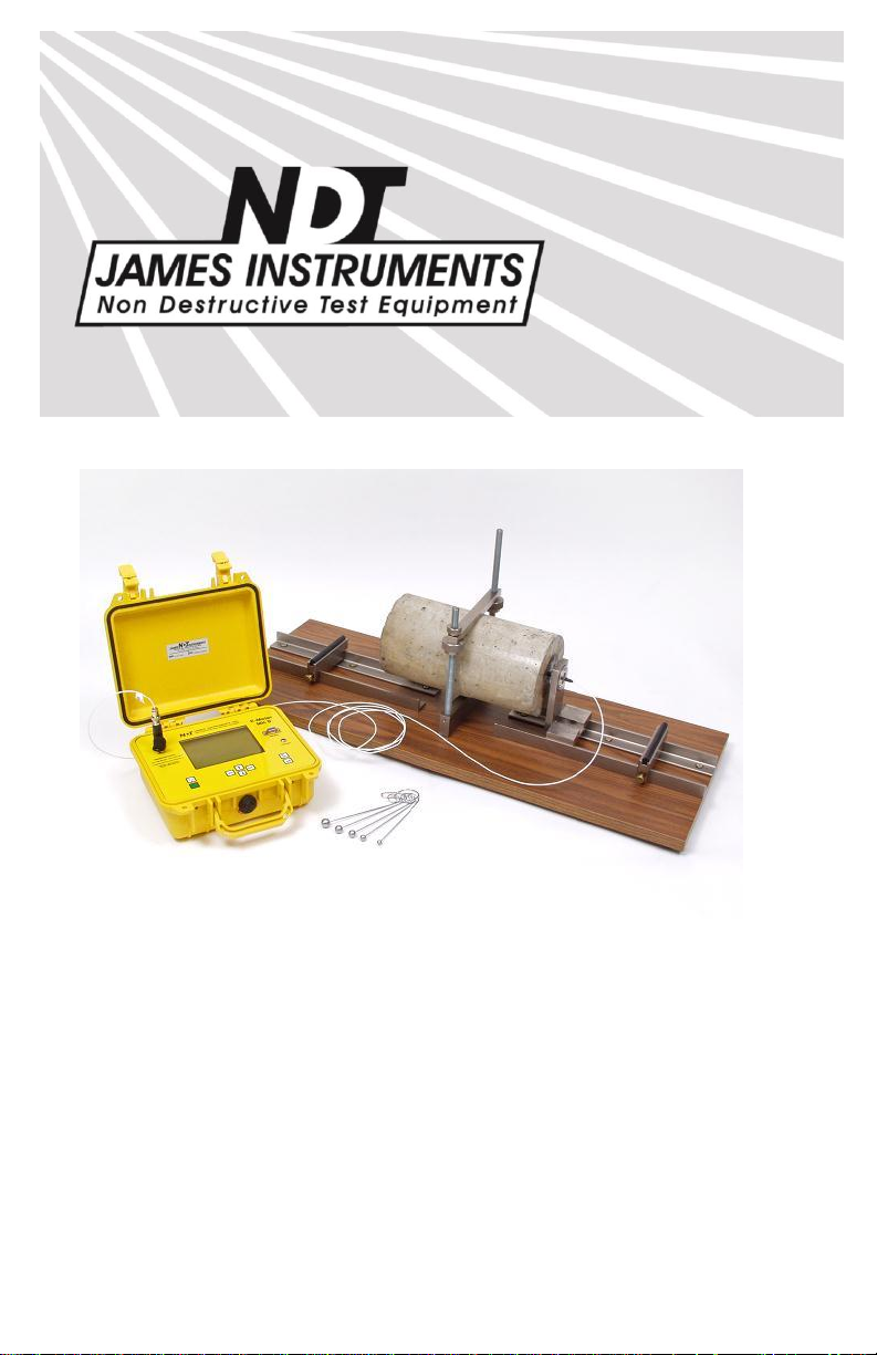
The instrument consists of the Resonant Frequency Tester, a test
bench for longitudinal, flexural and torsional resonance
measurements to take specimens up to 28” x 6” x 6”, a miniature
accelerometer is used as a receiver and a set of 6 hardened steel
balls are used to generate the vibrations on the sample by a
mechanical impact. In order to obtain the resonance frequency of
the sample, the received signal is analyzed in the time domain and
the frequency spectrum is displayed on the instrument’s screen.
The Emodumeter system comes with 6 different (steel) ball sizes:
6mm, 8mm, 10mm, 12mm, 14mm and 16mm. The maximum
frequency that can be generated by each size can be found in the
chart below.
Steel ball diameter = Maximum Resonant Frequency possible
6mm = 48.5 kHz max freq.
8mm = 36.4 kHz max freq.
10mm = 29.1 kHz max freq.
12mm = 24.3 kHz max freq.
14mm = 20.8 kHz max freq.
16mm = 18.2 kHz max freq.
(Note: All impactors sold and manufactured at James Instruments,
Inc. are made of steel.)
www.ndtjames.com 1
Page 8

Instrument Contents List
Instrument Contents List
Each Emodumeter comes with the following items included in the
carrying case.
Figure 1: Emodumeter Contents
2 www.ndtjames.com
Page 9

Item #
Description
1
Case – Used for carrying the Emodumeter and
accessories.
2
Emodumeter Instrument – Resonant Frequency
Tester encased in a durable protective case.
3
Instruction Manual – Operating instructions for
Emodumeter.
4
AC Power Adapter – Used to power the Emodumeter
and recharge the unit.
5
240 VAC Adapter Plug –
6
USB Cable – Serial cord used to connect the
Emodumeter to a PC to upload data.
7
Accelerometer Pickup Cable – Connected to
Sensor/Accelerometer.
Contents List
Testing Bench Contents List
www.ndtjames.com 3
Page 10

Testing Bench Contents List
Testing Bench Contents List
Each Emodumeter comes with a testing bench which has the
following items included.
Figure 2: Testing Bench Contents
Contents List
4 www.ndtjames.com
Page 11

Testing Bench Contents List
Item #
Description
1
Emodumeter Test Bench – Base for performing tests.
2
Flexural Spacer Assembly – Base, #2 and #3.
3
Torsion Block (#3) – Used with Items 9 and/or 12.
4
Rubber Cushions – 4”.
5
Mounting Bolts – Slide on Mounting Rod.
6
Sensor Mounting Rod – Assembly
7
Knurled Clamp Nuts – Used to Hold Sample and Item
11.
8
Pick-Up Mount Bracket Assembly – Used to Hold
Sensor (Accelerometer).
9
Torsion Block (#2) – Used with Item 12.
10
Impactor Set – 6, 8, 10, 12, 14, and 16mm.
11
Clamp/Bar – Used to Hold the Sample in Place.
12
Torsion Block (#1) Base – For Sensor Placement
along Concrete Sample. Used with Item #8.
www.ndtjames.com 5
Page 12
Emodumeter Overview
Emodumeter Overview
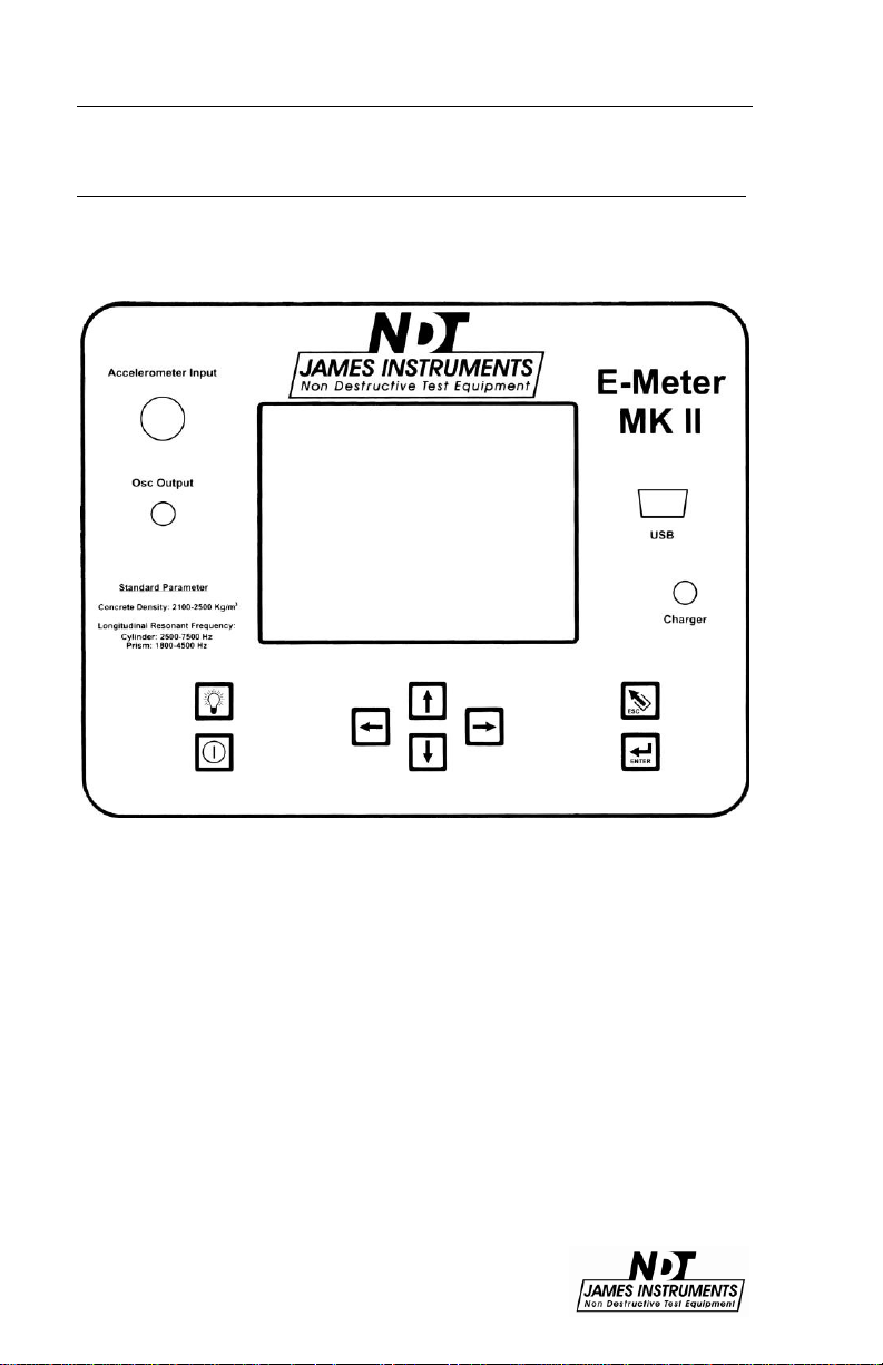
The following is an overview of all of the external features of the
Emodumeter.
Figure 3: Emodumeter Overview
6 www.ndtjames.com
Page 13

Emodumeter Overview
Key
Definition
The power button. Momentarily push this key to turn on
the unit. Pressing it again turns off the unit. The unit will
power up displaying the main menu screen.
The up arrow. This key is used to scroll through various
settings, wave frames and allows to increase input
values needed for calculations.
The down arrow. This key is used to scroll through
various settings, wave frames and allows to decrease
input values needed for calculations.
The left arrow. This key allows you to scroll through
various settings.
The right arrow. This key allows you to scroll through
various settings.
The Enter key. Pressing this key allows you to choose
main menu selections. The enter key also allows you to
prepare the Vu-Con for testing mode. Pressing the
enter key once will give you a message “Emodumeter
is Ready”. Pressing the key one more time a message
“Emodumeter is not Ready” will be displayed.
The Esc key. Pressing this key allows you to return to
the main menu screen from any sub screen.
The light button. Pressing this key the backlight of the
display comes on. Pressing the key again turns the
backlight off.
Control Panel Buttons
www.ndtjames.com 7
Page 14
Menu Layout
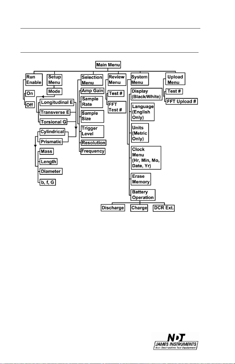
Menu Layout
Figure 4: Emodumeter Function Flow Chart
8 www.ndtjames.com
Page 15

Emodumeter Run Mode
Emodumeter Run Mode
In order to run the Emodumeter, you need to press the right or left
arrow key. The message will change from “Run enable is OFF” to
“Run enable is On”. After the system is in the “Run enable is On”
mode, the unit will trigger with the impact of the hardened steel ball
on the surface of the sample.
Caution: the system can be triggered with another event, different
than the impact of the steel ball on the sample. Once the unit is in
the mode “Run enable is On,” any contact with the specimen, cable
or accelerometer can trigger the instrument with a meaningless
signal.
Figure 5: Emodumeter screen showing the “Run Enable Mode”
www.ndtjames.com 9
Page 16

Emodumeter Setup Menus
Emodumeter Setup Menus
By pressing the “Enter” key, the user will be able to change the
testing parameters. The first option is the testing Mode. The user
can select Longitudinal (E), Transverse (E) or Torsional (G) by
using the left and right arrow keys. By pressing “Enter” in one of
these modes, the user can manually input the value of G or E,
needed to compute Poisson’s ratio. The unit will obtain one of
these values according to the testing Mode selected (the output of
the test) and will use the user input value for the other variable.
The other option that the user can control in the Setup Menu is the
shape of the specimen. According to the user selection, different
parameters related to the dimensions of the specimen will appear in
the same screen. The user can change the values using the left
and right arrow keys by pressing “Enter.” This action opens another
screen, allowing the user to control and change parameters before
running a test. The dimensions needed are the same that are
required by the ASTM C-215.
10 www.ndtjames.com
Page 17

Emodumeter Selections
Emodumeter Selections
The Emodumeter selection menu allows the user to select the
parameters for testing according to their needs. The Amplifier Gain
and Sample Rate can be adjusted to the user needs. The Sample
Size or number of data points recorded can be selected from 1024
to 2048 points. The trigger level can also be adjusted by the user
according to specimen characteristics.
Gain
On the main screen, scroll the cursor down using the up or down
arrow keys until you get to the Emodumeter selections menu option
and press enter. The Emodumeter enters a sub-screen; title of the
sub-screen should read Current Selections. Scroll the cursor to the
option to be changed. Use the right and left arrow keys to change
the values of the selected option. The gain shall be adjusted when
testing different specimens. The smaller the sample, the lower the
gain shall be. The gain can be adjusted from 1 to 500. The gain is
the ratio of an output quantity to an input quantity. The gain options
are as follows: 1, 5, 10, 25, 50, 100, 250, and 500.
Sampling rate and number of data points
The user can select the sampling rate and the number of points to
sample the signal according to the specific applications or
standards requirements. The selection of these parameters affects
the frequency resolution and the maximum frequency in the
spectrum.
Sampling frequency can be 10 kHz, 20 kHz, 40 kHz or 80 kHz. The
number of data points sampled can be 1024 or 2048 points. Figure
6 and 7 show the frequency resolution and the maximum frequency
for each combination of selections. In order to achieve the
minimum frequency resolution (4.9 Hz), the settings shall be a
sampling frequency of 10 kHz and signal length of 2048 data
points. Using these settings, a maximum frequency of 5 kHz can
be identified, and frequencies higher than 5 kHz are not detected
with these sampling parameters.
www.ndtjames.com 11
Page 18

Emodumeter Selections
1024 points
2048 points
80 kHz
78.1 Hz
39.1 Hz
40 kHz
39.1 Hz
19.5 Hz
20 kHz
19.5 Hz
9.8 Hz
10 kHz
9.8 Hz
4.9 Hz
Maximum
Frequency (kHz)
80 kHz
40
40 kHz
20
20 kHz
10
10 kHz
5
Figure 6: Frequency resolution for each combination of sampling frequency and
number of points
Figure 7: Maximum frequency (kHz) for different sampling frequency selections
The selection of sampling frequency and number of points shall
allow the user to identify frequencies with the needed accuracy and
in the required range of frequencies.
Trigger Level
The Trigger level is adjusted in percentages: 10%, 20%, 30%, 40%,
50%, 60%, 70%, 80%, and 90%. Pressing the escape keys the
system returns to the main menu, so test can be started. Lower
trigger level should be used when testing small samples. The
Trigger Level should be set to a level that the system records the
signal just after the impact and not before. When using low trigger
levels, environmental noise could trigger the system. Trigger level
should be increased because the system should only be activated
by the actual impact of the steel ball.
12 www.ndtjames.com
Page 19

Review Menu
Review Menu
The review menu allows the user to review previously recorded test
results. All the results and parameters used in the test are
presented in this menu. The user can review the FFT or the time
domain signal as well.
www.ndtjames.com 13
Page 20
System Setup
System Setup
The System Menu option on the main menu screen allows the user
to make modifications of the system configuration. The user can
change the date on the instrument, erase data or change the
display colors. It also, allows monitoring the battery operation. The
Emodumeter can only be set to use the English language.
Changing Date
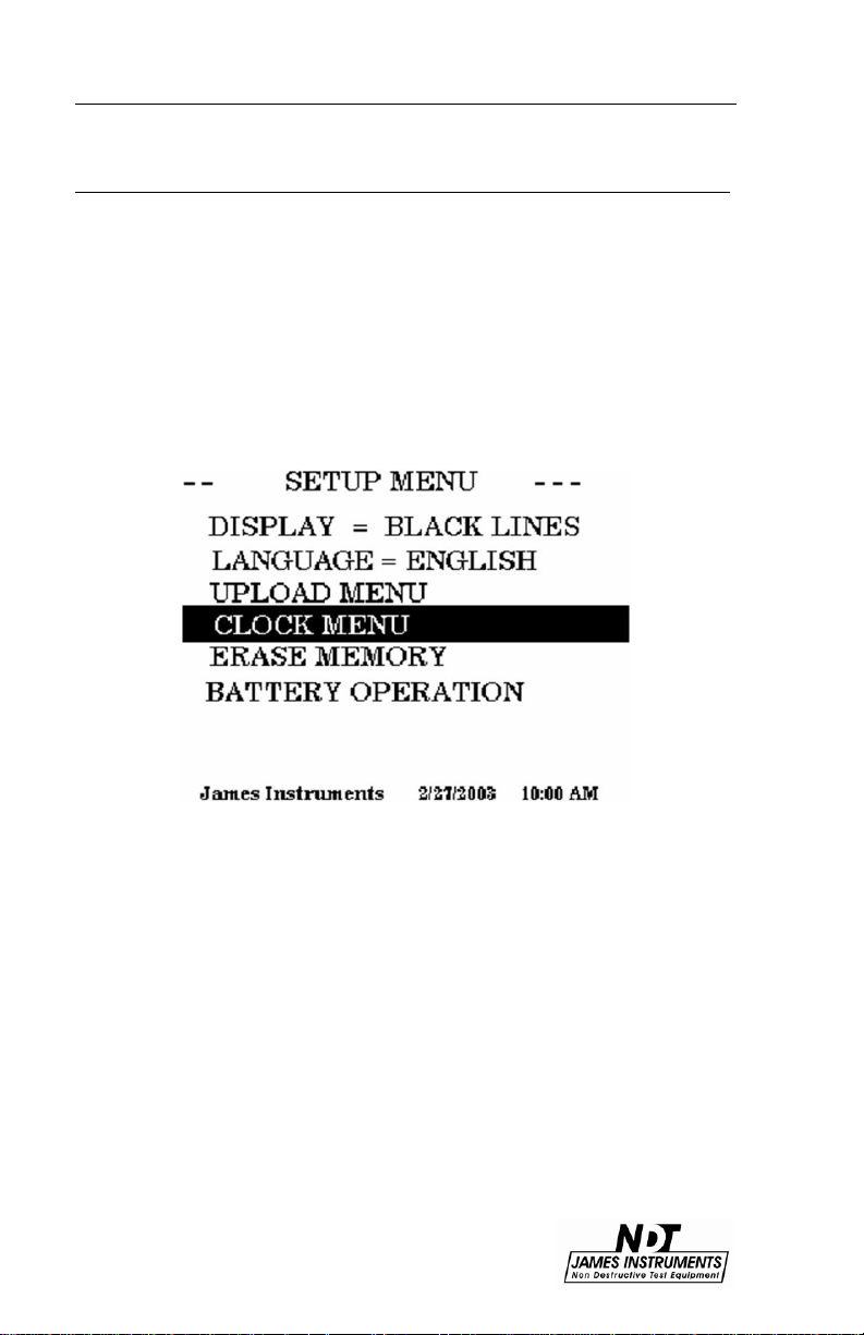
Press the up or down key until you get to the system setup menu
option.
Figure 8:
Press “Enter”, the setup Menu sub screen should appear.
14 www.ndtjames.com
Page 21

System Setup
Figure 9:
Hour= [1 PM ]
• Press the right or left arrow keys to set the proper hour, press the
down arrow key when hour has been set.
Minute= [ 0 ]
• Press the right or left arrow keys to set the proper minute, press
the down arrow key when minute has been set.
Month = [ 10 ]
• Press the right or left arrow keys to set the proper month, press
the down arrow key when month has been set.
Date = [ 12 ]
• Press the right or left arrow keys to set the proper date, press the
down arrow key when date has been set.
Year = [ 2003 ]
• Press the right or left arrow keys to set the proper year. You have
properly set the correct date and time of 10 / 12 / 2003, 1:00 PM,
press the down arrow key when date and time are ready to be
saved.
www.ndtjames.com 15
Page 22

System Setup
Figure 10:
Press “Enter” to save date and time. Then press enter to return you
to the main menu screen.
Erase Memory
• Press the up or down key until you get to the system setup menu
option. Press Enter. The Setup Menu sub screen should appear.
• Scroll through the Setup menu using the up or down arrow key.
Select the Erase Memory option by pressing “Enter”. The display
should read the following.
Figure 11:
16 www.ndtjames.com
Page 23

System Setup
• Press enter once and a message telling you to press enter again
should appear.
Figure 12:
• Pressing enter again will erase all stored memory in the
Emodumeter. Pressing the “Escape” key will return you to the Main
Menu Screen.
Display Cursor
• Press the up or down key until you get to the system setup menu
option. Press Enter. The Setup Menu sub screen should appear.
• Scroll through the Setup menu using the up or down arrow key.
Select the Display option by pressing enter.
• Pressing the left or right arrow keys will give the option to choose
Black Lines or White Lines.
www.ndtjames.com 17
Page 24

Battery Operation
Figure 13:
• Pressing the “Escape” key will return you to the Main Menu
Screen.
Battery Operation
The Rebarscope® uses a 14.4V Lithium-Ion battery with a built-in
thermo-sensing circuit. This circuit allows for a suitable charge,
and maintains the voltage to the cells (< 4.1V). Additionally, this
circuit provides the proper charge current to lengthen the
battery’s life.
At full charge, the bottom of the display will show
BATTERY=100%. (Note: This value may be inaccurate, if the
battery counters were reset without properly charging the unit.)
-
The battery status can be viewed in the “System
Menu”, under the “Battery Operation” mode. (Fig.14 &
15)
-
When the charger is supplying power to the unit, the battery
is charging, and the charge counter (“Charge CTR”) will
increase.
-
When the unit is ON, and the charger is disconnected from
the unit, the discharge counter (“Discharge CTR”) will
increase.
-
The battery will continue to charge even after the
18 www.ndtjames.com
Page 25

-- BATTERY STATUS-DISCHARGE CTR = xxxx
CHARGE CTR = xxxx
DCR EXT = 0
CCR EXT = 0
Hit ENT to Clear Reg
BATTERY = 100%
microcontroller times out - display and unit turn OFF
automatically.
Battery Operation
Figure 14: Battery Operation Menu is Highlighted
Figure 15: Clearing Charger Register
Battery Charge
1.
Connect the charger to a working outlet, and then to the
charger input on the unit’s front panel. Although, it is
recommended for the unit to be OFF during a charge, the user
can monitor the charging process in the screen above.
2.
If the Charge counter slows to a stop (and does not
increase), this is an indication the charge is complete. The
battery now has a full charge, and needs to be reset. To do
www.ndtjames.com 19
Page 26

Battery Operation
this, go to: Main Menu / System Menu / Battery Operation press “Enter” to zero the counters. This action also resets the
battery circuit mentioned above, and will correct any
miscounts. (If charging is still an issue, review the Repair Policy
on p.61.)
Resetting the battery counters should be done both
before and after (at least) a 4hr charge.
When done so, the battery status % on the display will be
accurate.
3.
When the Battery percentage reaches ~ 40-50%, be
sure to charge the unit again. (Go to step 1)
4.
A charged battery allows for 4-6 hours of continuous field
testing.
5.
To extend the battery’s run time in the field, to turn “OFF”
the background light.
Simple Guidelines for Battery Maintenance.
1.
When allowed to discharge and charge regularly, the end
user will experience a better Battery life span (or cycle).
2.
Lithium-ion batteries do not need to be fully charged; as
the charger can aid its performance.
3.
Shallow discharges provide more cycles than deep discharges.
4.
It is recommended to fully charge the unit (4-6hrs)
before a lengthy field test is performed.
5.
As a general rule, it is best to charge the battery both before
and after each use. There is no memory effect, so it is a good
practice to recharge the unit after each use, or at the end of the
day - if used daily.
20 www.ndtjames.com
Page 27

Upload Menu
6.
Charge the battery at a moderate temperature. Do not
charge below 0deg C (or < 32deg F).
7.
Lithium-Ion batteries suffer from stress when exposed to
heat. Therefore, to lengthen the life of the battery, avoid
elevated temperatures > 30deg C (or > 86deg F).
8.
Lithium-Ion batteries may fail when stored for long periods of
time in a discharged state. Thus, before a prolonged storage
period, be sure to apply a charge to the battery. It's
recommended once every 2 months to recharge the battery to
keep it fresh. You should store the Unit (and battery) during
this period at room temperature.
9.
Replacing or repair of the battery should be done by a
trained James Instruments technician. Please follow the repair
procedure found in the manual…. check the “Table of Contents”
in your manual.
Upload Menu
Connect the unit to the correct serial port of the P.C. using the
supplied serial cable. Press the up or down key until you get to the
system Upload menu option. Press “Enter”. The Upload Menu sub
screen should appear.
Figure 16:
Select the upload menu option by pressing “Enter”. The display
should read the following:
Use the up or down arrow key to select a TEST data or a FFT data.
Pressing the left or right arrow key you can select which TEST or
FFT data number you want uploaded. Open the Emodumeter
software on your PC. Press the Upload key on the tool bar or press
www.ndtjames.com 21
Page 28

Test Bench
Ctrl + U, the message “Please start Upload” will appear on your PC
screen. Then on the Emodumeter unit, press enter on the selected
Test and the upload process will begin. You can choose to upload
all of the tests stored in memory to the PC, or upload each test one
by one.
Note: During the FFT Upload, the Emodumeter will upload the last
FFT values to a PC in a few seconds. In order to upload another
record, the system will first calculate the Frequency Spectrum, and
after that the data will be ready to be transmitted to the PC.
Test Bench
Center support: the basic support has been arranged for the
accelerometer to be on the axial center line of a 6” x 12” cylinder or
6” x 6” square section specimen. For 4” dia. or 4” x 4” section a
spacer, marked 4, is placed on the basic support and for 3” dia. or
3” x 3” specimens a second spacer, marked 3, is added to the 100
spacer. Torsion spacer blocks, spacer blocks marked 1, 2, and 3
on which the accelerometer supports may be mounted are provided
for torsion testing. For 3” dia. and 3” x 3” square section
specimens, the accelerometer is mounted on blocks 1 plus 2, for 4”
dia. and 4” x 4” specimens use blocks 1 plus 3 and for 6” dia. and
6” x 6” specimens use blocks 1 plus 2 plus 3.
22 www.ndtjames.com
Page 29

Accelerometer
Accelerometer
The accelerometer is used to sense the vibrations of the specimen
caused by the impact of a hardened steel ball. In order for the
accelerometer to receive the vibrations, it should be in intimate
contact with the surface of the specimen. The sensing front of the
accelerometer should be touching the specimen. The use of the
accelerometer support allows placing the accelerometer at the
required location. The accelerometer should be inserted through
the rubber ring and then the cable should be connected to the
accelerometer microdot connector. The accelerometer does not
need to be screwed to the mounting stud base when using it with
the accelerometer support. The testing setup using the
accelerometer support is shown in Fig.18.
Figure 17: Accelerometer
Figure 18: Testing setup using the accelerometer support
www.ndtjames.com 23
Page 30

Testing Procedure
Another option is to attach the accelerometer to the surface of the
specimen without using the accelerometer support. It can be
attached to the specimen using an adhesive mounting base. Wax
is usually provided with the system to attach the accelerometer on
the surface of the specimen (as shown in Fig. 19).
Figure 19: Testing setup using the accelerometer support
24 www.ndtjames.com
Page 31

Testing Procedure
Testing Procedure
From the Main menu you can choose among 3 different test modes
(or methods):
• Longitudinal frequency (E)
• Transverse frequency (E)
• Torsional (G)
Longitudinal Frequency Mode
The Longitudinal Frequency mode is selected by placing the cursor
on the first line, and pressing ‘Enter’. For this mode the user can
input the desired value of the Modulus of Rigidity (G) that will be
used for the Poisson’s Ratio calculations.
The user should input the required parameters below using the
arrow keys:
Specimen’s shape – Cylindrical or Prismatic
M: mass of the specimen (kg)
L: length of the specimen (m)
d: diameter of cylinder (m)
t, b: dimensions of cross section of prism (m), t being the driver (or
impact) direction in which it is driven (Note: It is important to
distinguish between t and b for transverse frequency).
G: assumed Modulus of Rigidity value in order to compute (μ)
Usually, the user has to input the value of G in G Pa obtained in a
previously run Torsional test.
E: assumed Modulus of Elasticity value in order to compute μ.
Usually, the user has to input the value of E in G Pa obtained in a
previously run Longitudinal or Flexural test.
The system provides the fundamental longitudinal frequency (n’)
from the FFT, frequency value of the maximum Amplitude on the
FFT, which is applied to a time domain signal obtained by slightly
tapping the cylinder with a small hardened steel ball.
www.ndtjames.com 25
Page 32

Testing Procedure
The system will calculate the dynamic Young’s Modulus of elasticity
according to eq. (i), using obtained and computed parameters:
M= mass of the specimen (kg)
n’= fundamental longitudinal frequency (Hz.)
D= 5.093 (L/d²) for a cylinder (N s ² /(kg m² )) or
D= 4 (L/bt) for a prism (N s ² /(kg m² ))
E = D M (n’)² (i)
With these parameters the system will compute the elastic
constants of the specimen. If only frequency values are required,
the system will assume default values and the elastic constants are
not going to have any meaning.
When testing for the fundamental longitudinal resonant frequency,
there is one nodal point at the center on the longitudinal direction of
a prism or cylinder and the specimen should be placed on the test
bed center support at the nodal point (see Fig. 20). The specimen
may be simply supported or clamped by the clamping bar provided.
Figure 20: Longitudinal resonance frequency setup
26 www.ndtjames.com
Page 33

Testing Procedure
Figure 21: Testing for longitudinal resonance frequency
Place the accelerometer on the required location (contact point at
the center of the face), intimate contact between accelerometer and
specimen is required. For the ends of the specimens to be free to
vibrate in a longitudinal direction, it is essential that minimum
restraint is imposed on the ends. The accelerometer is free to
move in compliant mountings and it is necessary only to move the
accelerometer support along the rails until the contact tip of the
accelerometer just make contact with the center of the ends of the
specimen. A coupling agent may be used to assure good contact
between them (a coupling agent may be required to assure intimate
contact). The support may now be locked by using the knurled
clamping screws. The accelerometer may also be placed on the
surface of the specimen without using its support. It could be
attached on the surface of the specimen by using wax and pressing
it against the surface (as described in the “Review Menu” chapter).
By pressing the right arrow key, the message “Run enable is On”
will appear on the screen. Then tap the specimen using a
hardened steel ball, causing the instrument to trigger and a signal
will appear in the screen. Caution should be taken to apply just one
solid impact; otherwise the test should be performed again because
the results are not going to be consistent. It is recommended to
repeat the test three times to check the consistency of the results.
www.ndtjames.com 27
Page 34

Testing Procedure
Specimen dimensions (inches)
Approximate range
of Frequency (Hz.)
6” x 6” x 30”
1700 – 3000
6” x 6” x 28”
2000 – 3200
4” x 4” x 30”
1700 – 3000
4” x 4” x 20”
3000 – 4500
4” x 4” x 12”
5000 – 7000
6” x 12” cylinder
5000 – 7000
In order to obtain the spectrum of the signal and the resonance
frequency, the Enter key should be pressed. On the screen will
appear the message “calculating spectrum please wait”. It will take
approximately 45 seconds.
The system will show the fundamental frequency from the FFT,
frequency value of the maximum amplitude on the FFT.
The system will obtain the fundamental frequency from the FFT.
The fundamental frequency will appear on the first screen with the
corresponding value. In order to view the complete frequency
spectrum, you can use the left and right arrow key to change from
different screens. The frequency spectrum is presented in 2 to 4
different screens.
For concrete specimens the resonance frequency will generally be
in the range 1 kHz to 10 kHz depending on the dimensions of the
specimen (see Figure 22).
Figure 22: Range of longitudinal fundamental resonant frequencies of concrete prism
and cylinder specimens
The system will calculate the dynamic Poisson’s ratio according to
eq. (ii), using the obtained value of (E) from the Longitudinal test
and assuming a value of (G) that shall be input before to run the
Longitudinal test.
In order to obtain a meaningful result of µ, it is recommended to run
a Torsional test beforehand to obtain a value of (G) and then input
this value as a parameter to compute the Poisson’s ratio.
28 www.ndtjames.com
Page 35

Testing Procedure
Mu= E/(2G) – 1 (ii)
(E): Dynamic Young’s Modulus of elasticity (obtained according eq.
(i))
(G): Dynamic modulus of rigidity (input by the user, the
recommended value of (G) is the obtained in a previous Torsional
test).
Transverse Frequency Mode
In order to obtain the elastic constant of the specimen in the
transverse or flexural mode, the user should input some data. By
placing the cursor on the first line and pressing the enter key the
user can input the desire value of Dynamic Modulus of Rigidity (G)
that is going to be used for the computations. The user should also
input a Dynamic Poisson’s ratio (µ) value, otherwise the default
value would be (µ= 0.17).
The system will calculate the dynamic Young’s Modulus of elasticity
according to e.q. (iii), using obtained and computed parameters:
M= mass of the specimen (kg)
n= fundamental transverse frequency (Hz.)
t, b= dimensions of cross section of prism (m), t being in the
direction in which it is driven (distinguish between t and b is
important for transverse frequency).
C= 1.6067 (L³T/d^4), Ns² /(kg m²) for a cylinder or
C= 0.9464 (L³T/bt³), Ns² /(kg m²) for a prism
K= d/4 (m) for cylinder or
K= t/3.464 (m) for prism
T is obtained according to Table 4, using (K/L) and (µ).
E = D M n² (iii)
At the fundamental transverse resonant frequency there are two
nodal points, at distances from each end of 0.224 times the length.
Position the supports for transverse vibration 0.224 times the
specimen length from the ends as shown in Fig. 23. Place the hard
rubber circular rods in the grooves of the supports.
www.ndtjames.com 29
Page 36

Testing Procedure
Figure 23: Transverse resonance frequency testing setup
The accelerometer can be placed using the accelerometer support
or by placing a spot of wax on the underside of the surface
mounting accelerometer onto the top surface at the middle of the
specimen. The accelerometer can be placed without the
rectangular support or with it as shown in the picture. Connect
surface mounting accelerometer to the instrument.
By press the right arrow key, the message “Run enable is On” will
appear on the screen. Then tap the specimen using a hardened
steel ball, the instrument will trigger and a signal will appear in the
screen. In order to obtain the spectrum of the signal and the
resonance frequency, the down arrow key should be pressed. On
the screen will appear the message “calculating spectrum please
wait”. It will take a few seconds. The system will obtain the
fundamental transverse frequency (n) from the FFT, frequency
value of the maximum amplitude on the FFT (frequency spectrum)
will be presented on the top of the screen.
The frequency spectrum is presented in 2 to 4 different screens;
you may use the left and right arrow key to change from different
screens.
30 www.ndtjames.com
Page 37

Testing Procedure
Values of correction factor, T
K/L
Mu=017
Mu=0.20
Mu=0.23
Mu=0.26
0 1 1 1 1
0.01
1.01
1.01
1.01
1.01
0.02
1.03
1.03
1.03
1.03
0.03
1.07
1.07
1.07
1.07
0.04
1.13
1.13
1.13
1.14
0.05
1.2
1.2
1.21
1.21
0.06
1.28
1.28
1.29
1.29
0.07
1.38
1.38
1.39
1.39
0.08
1.48
1.49
1.49
1.5
0.09
1.6
1.61
1.61
1.62
0.1
1.73
1.74
1.75
1.76
0.12
2.03
2.04
2.05
2.07
0.14
2.36
2.38
2.39
2.41
0.16
2.73
2.75
2.77
2.8
0.18
3.14
3.17
3.19
3.22
0.2
3.58
3.61
3.65
3.69
0.25
4.78
4.84
4.89
4.96
0.3
6.07
6.15
6.24
6.34
Note: Values for Poisson’s ratio for concrete normally vary
between about 0.10 dry specimens and 0.25 for saturated
specimens.
Figure 24: Values of Correction Factor, T
www.ndtjames.com 31
Page 38

Testing Procedure
Size of the specimen
(inches)
Approximate range
of Frequency (Hz.)
6” x 6” x 30”
550 – 1050
6” x 6” x 28”
600 – 1150
4” x 4” x 36”
400 – 750
4” x 4” x 20”
900 – 1500
4” x 4” x 12”
2500 – 4500
6” x 12” cylinder
2500 – 4500
Figure 25: Range of flexural fundamental resonant frequencies of concrete prism
and cylinder specimens
The system will calculate the dynamic Poisson’s ratio according to
eq. (ii), using the obtained value of (E) from the Transverse test and
assuming a value of (G) that shall be input before to run the
Transverse test. In order to obtain a meaningful result of Mu, it is
recommended to run a Torsional test before to obtain a value of (G)
and then input this value as a parameter to compute the Poisson’s
ratio.
Mu= E/(2G) – 1 (ii)
(E): Dynamic Young’s Modulus of elasticity (obtained according eq.
(iii))
(G): Dynamic modulus of rigidity (input by the user, the
recommended value of (G) is the obtained in a previous Torsional
test).
Torsional Frequency Mode
The system will obtain the fundamental torsional frequency (n’’)
32 www.ndtjames.com
Page 39

Testing Procedure
Size of the specimen
(inches)
Approximate range
of Frequency (Hz.)
6” x 6” x 30”
1150 – 1800
6” x 6” x 28”
1200 – 1920
4” x 4” x 30”
1150 – 1800
4” x 4” x 20”
1800 – 2700
4” x 4” x 12”
3000 – 4200
6” x 12” cylinder
3000 – 4200
from the FFT (frequency value of the maximum Amplitude on the
FFT), which is applied to a time domain signal obtained by slightly
tapping the cylinder with a small hardened steel ball.
The configuration of the test varies according to the shape of the
specimen. Different standards have specifications about sensor
location and impact location.
The system should calculate the dynamic modulus of rigidity
according to eq. (iv), using obtained and computed parameters:
G= B M (n’’)2 (iv)
n’’ = fundamental torsional frequency (Hz)
B= 4LR/A, (N s2 /(kg m2))
R = 1 for a circular cylinder
R = 1.183 for a square cross section prism,
R = (a/b+b/a) /(4a/b-2.52(a/b)2+0.21(a/b)6) for a rectangular prism
whose cross-sectional dimensions are a and b (m) with a less than
b
A= cross-sectional area of test specimen (m2)
Figure 26: Range of torsional fundamental resonant frequencies of concrete prism
The system will calculate the dynamic Poisson’s ratio according to
eq. (ii), using the obtained value of (G) from the test and assuming
a value of (E) that shall be input before to run the Torsional test. In
and cylinder specimens
www.ndtjames.com 33
Page 40

Testing Procedure
order to obtain meaningful results, it is recommended to run before
a Longitudinal or Flexural test to obtain a value of (E) and then
input this value as a parameter to compute the Poisson’s ratio.
Mu= E/(2G) – 1 (ii)
(G): Dynamic modulus of rigidity (obtained according eq. (iv))
(E): Dynamic Young’s Modulus of elasticity (input by the user, the
recommended value of (E) is the obtained in previous Longitudinal
or Flexural tests).
Figure 27: Torsional resonance frequency testing setup (rectangular, side view)
Figure 28: Torsional resonance frequency testing setup (circular, front view)
34 www.ndtjames.com
Page 41

Emodulinx Introduction
Operating System
Windows Vista or Windows 7
Memory
1 GB RAM
Processor
1 GHz Pentium class processor
Capacity
1 MB hard drive space
Emodulinx Introduction
The Emodumeter’s Emodulinx software enables the user to upload
data from the Emodumeter device to a PC. The saved data can be
read in and graphed. Emodulinx also can be used to control the
Emodumeter remotely. Configuration settings can be adjusted, and
new data sets can be collected, all remotely. When commanded
remotely to take a new set of data measurements, the Emodumeter
will upload the new data to the PC, and Emodulinx will
automatically save the data to a file. Existing individual data sets
can also be uploaded and graphed to further analyze the
Emodumeter data. The addition of the remote control functionality
makes the Emodumeter a very powerful tool.
Features
The ability to execute a test remotely and graph FFT.
The ability to review previous test parameters.
The ability to adjust Test menu, Setup menu, and E/Mu
menu parameters. These items include: the amplifier
gain, the picture rate, the pulser voltage, the E or Mu
calculation method, the material density, the
measurement mode, the materials travel distance or
time, the cycle time, and the number of pulses per
sequence.
Minimum System Requirements
Emodulinx V-E-420
www.ndtjames.com 35
Page 42

Emodulinx Overview
The following is an overview of all of the features of the Emodulinx
software. Notice that mostly all menus and settings are the same as
the ones found in the Emodumeters menus and settings.
Consequently, the same basic operation and testing procedure
mentioned earlier in this manual will be used for Emodulinx.
Additionally, any settings that are changed in Emodulinx will
automatically save in the Emodumeter.
Figure 29: Emodulinx Overview
36 www.ndtjames.com
Page 43

Name
Description
Setup
Use this menu to specify the type of test to be
performed and shape of the concrete sample (see
page 10).
Selection
Use this menu to select the testing parameters (see
page 11-12).
Review
Use this menu to review previously recorded test
results (see page 13).
Upload
Use this menu to upload data from the Emodumeter
to a PC (see page 20).
FFT
Use this menu to graph FFT (see page 13).
Menu Descriptions
www.ndtjames.com 37
Page 44

Software Installation
The PC software that has been developed for the Emodumeter is
for data upload purposes. To install the software on your PC follow
these instructions.
To install the software:
1. Insert the Emodumeter PC Software CD into the CD-ROM
drive.
2. If the CD does not load the setup automatically, go to My
Computer, double click on the CD under devices and double
click on setup.exe.
Figure 30: Installation File Location
38 www.ndtjames.com
Page 45

3. The InstallShield Wizard checks for the operating system you
are using.
Figure 31: InstallShield Wizard
4. The InstallShield Wizard dialog appears. Click Next to proceed.
Figure 32: InstallShield Wizard
www.ndtjames.com 39
Page 46

5. Accept the terms in the license agreement and click Next.
Figure 33: License Agreement Screen
6. Complete the customer information fields and click Next.
Figure 34: Customer Information Screen
40 www.ndtjames.com
Page 47

7. The InstallShield Wizard confirms your installation. Click Install
to continue.
Figure 35: InstallShield Wizard Confirmation
8. The installation progress screen appears.
Figure 36: Installation Progress Screen
www.ndtjames.com 41
Page 48

9. When the installation has completed the following message will
appear. Click Finish to close the dialog.
Figure 37: InstallShield Wizard Completed
10. The Emodulinx shortcut appears on the desktop as well as the
Start Menu.
Figure 38: Emodulinx Shortcut
42 www.ndtjames.com
Page 49

Connecting the Emodumeter
To run Emodulinx, it is required for the Emodumeter to be
connected to the PC via the USB cable. Before running Emodulinx,
connect one end of the USB cable to the PC and the other end to
the Emodumeter. When connecting to the Emodumeter, push the
connector down firmly until it clicks. This will ensure that the
Emodumeter is properly connected.
After connecting the Emodumeter, you may run and use Emodulinx.
If you are experiencing difficulties, refer to the “Tips and
Troubleshooting” section of this manual (page 51).
www.ndtjames.com 43
Page 50

Overview of Menus
Setup Menu
Figure 39: Emodulinx Setup
Mode
Select the radio button of the type of test you wish to perform.
Shape
Select the radio button that best describes the shape of the
concrete sample that you wish to test.
Mass
Specify the mass of the specimen here.
44 www.ndtjames.com
Page 51

Length
Specify the length of the specimen here.
Diameter (Cylindrical Only)
Specify the diameter of the specimen here.
Mu (Transverse E Only)
Specify the Dynamic Poisson’s Ratio here (default is .17).
b>a, a<b (Prismatic Torsional G Only)
Specify the cross-sectional dimensions of the prism, where “a” is
less than “b”.
b, t (Prismatic Longitudinal E and Prismatic Transverse E Only)
Dimensions of the prismatic cross-section, with the “t” dimension
being the direction of impact.
www.ndtjames.com 45
Page 52

Selection Menu
Figure 40: Selection Menu
Amplifier Gain
Use this setting to amplify the received signal. See Tips and
Troubleshooting for more information (page 51).
Sample Rate
Use this setting to adjust the sampling frequency.
Sample Size
Use this setting to specify the number of data points sampled.
Trigger Level
Use this setting to adjust the vibration sensitivity of the
accelerometer.
46 www.ndtjames.com
Page 53

Review Menu
Figure 41: Review Menu
Review Number
Adjust this number to upload a summary of a given test, 1 being the
first test that is stored on the Emodumeter.
Upload Review
Click this button after changing the review number to refresh the
display window with a review of that particular test.
www.ndtjames.com 47
Page 54

Upload Menu
Figure 42: Upload Menu
Test Number
Adjust this number to upload all data of a given test, 1 being the
first test that is stored on the Emodumeter.
Upload Test
Click this button after changing the test number to upload the stored
data of that particular test. The upload takes a few minutes. A bar
will display underneath that shows that the upload is in progress
and it will disappear when the upload is complete.
Save Test
Click this button to save the uploaded test to your PC.
48 www.ndtjames.com
Page 55

Upload All Tests
Click this to upload all stored tests on the Emodumeter.
Save All Tests
Click this to save all tests from the “Upload All Tests” operation to
your PC.
www.ndtjames.com 49
Page 56

FFT Menu
Figure 43: FFT Menu
Run Enable
Check this box right before you are ready to test so the device can
begin gathering data. After performing the test, the FFT graph
eventually displays in Emodulinx.
Save FFT
Click here to save the current FFT data to your PC.
50 www.ndtjames.com
Page 57

Tips and Troubleshooting
In this section, some of the problems that could arise with the use
of the instrument are mentioned as well as recommendations for
solving each of them are described.
Sampling Frequency and frequency resolution
The sampling frequency and the number of collected points will
affect the accuracy and precision of your results.
The sampling frequency will determine the maximum frequency that
will be useful in the frequency spectrum, which is known as the
Nyquist frequency. This value is one half of the sampling frequency
and data from the frequency spectrum higher than that are useless.
In order to be able to obtain the resonance of the specimen, you
need to select a higher sampling frequency than the expected
resonance frequency (for concrete usually less than 10 kHz, so
sampling frequencies of 20 kHz or higher are recommended).
Contact accelerometer
It is important to place the accelerometer in contact with the
specimen. Checking accelerometer contact before impact the
specimen with the hardened steel ball is recommended. Coupling
between accelerometer and specimen assures proper testing
results. For more information, please refer to the recommendations
presented in the Operating Instructions chapter.
Trigger level
The trigger level should be adjusted to the particular testing
conditions. The level should allow you start recording the vibration
of the specimen right after the specimen is hit with the hardened
steel ball. A very low trigger level would trigger the system with a
different event than the impact of the steel ball. On the other hand,
a very high trigger level will not trigger the system even after it is
impacted with the steel ball. So, the user shall decide which trigger
level is more convenient for the particular testing conditions.
Gain
The gain allows you to control the amplitude of the received signal.
www.ndtjames.com 51
Page 58

If you select a high gain, the amplitude will get cut-off at higher
amplitude values (as presented in Fig. 44) and the obtained
frequency result will be different than the actual value. The gain
should be selected in order to obtain the best view in the screen of
the entire amplitude of the waveform (as presented in Fig. 45).
When the beginning of the signal seems to be cut off by the frame
of the plot, the gain should be reduced. On the other hand, when
the signal on the screen is very small in relationship to the plot
frame, the gain should be increased. The ideal gain is the one
where the waveform should be horizontally center in the graph and
the features of the waveform can be easily seen on the screen.
Figure 44: Time domain signal obtained using a high Gain
Figure 45: Time domain signal obtained with the proper Gain value
Missing Drivers (Emodulinx)
This is a known issue on some PCs that prevents Emodulinx from
52 www.ndtjames.com
Page 59

recognizing the Emodumeter while plugged in. If your Emodulinx
software brings up a “Emodumeter Not Found” dialog box upon
launch, first make sure the USB cable is firmly plugged in (you will
hear a click) and make sure the Emodumeter is turned on. If the
dialog box still appears, follow these steps:
1. Right click “Computer” in your Start Menu or Desktop and
click “Properties”. Select “Device Manager” from the left
hand side. The Device Manager will open.
2. With the Emodumeter on, unplug the USB cable and plug it
back in. If you see an item on the Device Manager appear
with a small yellow exclamation point, this means that the
device was detected but there are no supported drivers
available on the PC.
3. Make sure the Emodulinx install CD is inserted. Right click
the device icon with the exclamation point and select
“Update Driver Software”. Select “Browse my computer for
driver software”. Click the “Browse” button and navigate to
your CD drive. Double click the “USB Drivers” folder and
select either the folder called “32-bit” or “64-bit” depending
on what operating system you have installed. Click “Next”
and your computer will extract the drivers from the CD and
install them to the appropriate location on your PC.
The Emodumeter should now be displayed in the Device Manager
as “USB Serial Port (COM#)”, as shown in Figure 46.
www.ndtjames.com 53
Page 60

Safety
Figure 46: Device Manager
Do not submerge unit in water. This can cause electrical
shock.
54 www.ndtjames.com
Page 61

Part #
Description
V-E-400
Emodumeter Standard Test System
V-E-410
Emodumeter Instrument only
V-E-1020
Accelerometer
V-E-1030
Standard Bench
V-E-1040
Accelerometer and Standard Bench
Specifications
Emodumeter V-E-400
Frequency Range from 10 Hz to 40 kHz
Sampling Frequency 10, 20, 40 or 80 kHz
Frequency Resolution from 4.9 to 78.1 Hz
Record Length 1024 or 2048 points
Output Bias Level 9.2 V
Accelerometer Sensitivity 9.60 mV/g (0.979 mV/m/s2)
Battery 14.4 Volt. 4-8 hours - continuous
use
Display 320 by 240; backlit for daylight use
Storage 200 plus readings
Software Requirements Windows compatible 9x/me 32MB
RAM
Impactors Set of 6 hardened steel balls
Operating Temp. Range 0°C to 40°C
Sales Numbers
www.ndtjames.com 55
Page 62

Warranty Information
1. Contract
Unless otherwise stated all sales transactions are expressly subject to these
terms and conditions. Modification or additions will be recognized only if
accepted in writing by an authorized Officer of James Instruments Inc.
(hereinafter referred to as “James” or the “Company”), or an officially
designated representative. PROVISIONS OF BUYER'S PURCHASE ORDER
OR OTHER DOCUMENTS THAT ADD TO OR DIFFER FROM THESE TERMS
AND CONDITIONS ARE EXPRESSLY REJECTED. NO WAIVER OF THESE
TERMS AND CONDITIONS OR ACCEPTANCE OF OTHERS SHALL BE
CONSTRUED AS FAILURE OF THE COMPANY TO RAISE OBJECTIONS.
2. Warranties
The Company only warrants the equipment manufactured or supplied by the
Company as set forth herein. James makes no other warranties, either
expressed or implied (including without limitation, warranties as to
merchantability or fitness for a particular purpose). In no event shall James be
liable for any type of special, consequential, incidental, or penal damages,
whether such damages arise out of or are a result of breach of contract,
warranty, negligence, strict liability or otherwise. Warranty shall not apply where
the equipment manufactured or supplied has been subject to accident,
alteration, misuse, abuse, improper storage, packing, force majeure, improper
operation, installation, or servicing. In addition, the following shall constitute the
sole and exclusive remedies of Buyer for any breach by James of its warranty
hereunder.
a. New Products
James warrants the equipment manufactured or supplied by James
as set forth herein. This limited warranty can only be exercised by the
original purchaser of the equipment from James or authorized James
Agent and is not transferable to any subsequent owner or party. This
limited warranty gives you specific legal rights, and you may also have
other rights which vary from case to case.
i. For James Equipment
James warrants that James's equipment will be free from
defects in materials and workmanship for a period of twentyfour (24) months on the electronic portion and six (6) months
on the mechanical portion from the date of shipment of
equipment from James to Buyer. Should any defects be
found and reported by the Buyer during the applicable
limited warranty period, the defect will be corrected upon
return of the item to James. James will, during the applicable
new equipment warranty period, provide the necessary
replacement parts and labor to correct the defect.
56 www.ndtjames.com
Page 63

Excluded from the new equipment warranty are all
consumable and wear and tear items such as impact bodies,
penetrators, connection cables, etc. These items are subject
to usual wear and tear during usage. Refer to the
Consumable, Wear and Tear Items section of this warranty
document.
Option For Extended Limited Warranty Coverage
The original purchaser of any new equipment of James
which have been identified or labeled by James from time to
time in James's sole discretion as being eligible for extended
warranty coverage shall have the option to purchase certain
extensions of the applicable limited warranty provided
hereunder to the electronic portion of any such items for
either a twelve (12), twenty-four (24) or thirty-six (36) month
period (up to a possible maximum limited warranty coverage
period for the electronic portions of such new James
equipment of sixty (60) months) by purchasing any such
twelve (12), twenty-four (24) or thirty-six (36) month limited
warranty extension period either all the time of the purchase
of any such item(s) or within ninety (90) days from the date
of delivery of the subject item(s) of the original purchaser of
such item(s). The price for each such extended limited
warranty coverage period shall be as determined by the
Company from time to time and all such purchases of any
extended warranty coverage periods shall only be effective
upon a completed purchase order and payment directly
between James and the original purchaser of any such
item(s). The extended warranty coverage periods are only
valid with respect to the original purchaser of such item(s)
from the Company and such extended warranty coverage is
not transferable to subsequent owners of the subject item(s)
or any other parties. Upon the purchase of any extended
limited warranty coverage period, the Company will issue a
certificate to Buyer evidencing the details of the applicable
extended warranty coverage period purchased by the Buyer.
ii. For Other Manufacturer's Products Supplied by
James
Products of other manufacturers supplied as such by James
are warranted by James only to the extent of any warranty
provided by the original manufacturer, if any.
iii. For Parts and Sub-Assemblies
Parts or sub-assemblies purchased by the Buyer to perform
its own repair work etc. are warranted as provided
hereunder by James for six (6) months from date of
shipment of material from James to Buyer.
www.ndtjames.com 57
Page 64

iv. For Consumables, Wear and Tear Items
James supplies consumable items and items subject to wear
and tear during normal usage of James supplied products.
These items are not covered under warranty. Buyer is to
check for proper fit, form and function of such items upon
receipt of such items. In case of a defect condition, Buyer
can return the item to James for evaluation within thirty (30)
days of the date of shipment to the Buyer. James reserves
the exclusive right to issue full, partial, or no credit to the
Buyer based on the condition of the returned item and
circumstances related to the return. Examples of items in
this category: connection cables, test blocks, impact bodies,
penetrators, probes, extraction liquids, calibration liquids,
pins, recording paper, test plugs, etc.
b. Calibration and Repair
i. For Calibration Services
James does not warrant the calibration of any equipment.
James does however warrant the equipment manufactured
by it, in proper working condition, to be capable of being
adjusted to meet James printed specifications, if any, for
accuracy and performance as to the particular model type
during the period of warranty applicable as stated above.
ii. For Repair Services
James warrants repair work performed under the direct
control and supervision of James personnel for a period of
three (3) months from the date repairs are completed either
at James or at the customer site. Should the defect for which
the repair work was performed reoccur within this period,
James will supply the necessary parts and labor (repair at
James facility) or parts (repair at Buyer facility) required to
repair the original equipment defect for which the repair
parts and labor were required. Additional repair charges that
may be incurred in conjunction with any repair service
warranty event will be invoiced at the James customer
service rates and policies in effect at the time of the event.
Excluded are all consumable and wear and tear items such
as impact bodies, probes, connection cables, etc. These
items are subject to usual wear and tear during usage. Refer
to the Consumable Wear and Tear Item section of this
warranty document.
58 www.ndtjames.com
Page 65

c. Warranty Claims
i. For Warranty Claim Processing
James has established James organizations in the
Americas, and Europe. Please visit the James web site
www.ndtjames.com for latest address and contact
information for the James organization nearest you.
3. Regulatory Laws and/or Standards
The performance of the parties hereto is subject to the applicable laws of the
United States. The Company takes reasonable steps to keep its products in
conformity with various nationally recognized standards and such regulations,
which may affect its products. However, the Company recognizes that its
products are utilized in many regulated applications and that from time to time
standards and regulations are in conflict with each other. The Company makes
no promise or representation that its product will conform to any federal,
provincial, state or local laws, ordinances, regulations, codes or standards
except as particularly specified and agreed upon for compliance in writing as a
part of the contract between Buyer and the Company. The Company prices can
not include the cost of any related inspections or permits or inspection fees.
4. Notices
Notice by either the Company or Buyer will be made only by facsimile or similar
electronic transmission, effective on the first business day after confirmed
receipt, or by letter addressed to the) other party at its address as provided in
this Agreement, effective three (3) business days after deposit with the U.S.
Postal Services, postage prepaid, or one (1) business day after deposit with a
recognized overnight express service.
5. Interpretation
Should any term or provision contained In the contract contravene or be invalid
under applicable law, the contract shall not fail by reason thereof but shall be
construed in the same manner as if such term or provision had not appeared
therein.
6. Assignability
Neither this contract nor any claim arising directly or indirectly out of or in
connection herewith shall be assignable by Buyer or by operation of law,
without the prior written consent of Company. This document shall be binding
upon and inure to the benefit of each party hereto and their respective
permitted successors and assigns.
www.ndtjames.com 59
Page 66

7. Governing Law
This Agreement shall be governed by and construed in accordance with the
internal laws of the State of Illinois, without regard to its conflict of laws
provisions. Buyer and the Company expressly agree to submit to the personal
jurisdiction of the federal and/or stale courts silting in Chicago, Illinois, U.S.A.
and agree that such courts may be utilized if necessary to obtain injunctive or
any other relief. The Hague Convention and the United Nations Convention on
Contracts for the International Sale of Goods shall not apply to the construction
or interpretation of these Standard Terms and Conditions or affect any of its
provisions.
END.
60 www.ndtjames.com
Page 67

Attn: Repair Department
James Instruments, Inc. - USA
3727 North Kedzie Avenue
Chicago, IL 60618-4503
USA
Attn: Repair Department
James Instruments, Inc. – Europe
Windmolen 22
7609 NN Almelo
The Netherlands
Repair Policy
United States | Canada | International
Ship the instrument in a box that meets UPS, Fed Ex, and standard
shipping regulations. Enclose a note describing the problem(s) you
are having. Include the name and phone number of the contact
person in your organization.
The instrument will be evaluated within one week of receipt. The
contact person will be notified with an estimate of the cost of the
repair.
Upon receipt of your authorization of repair and payment terms,
delivery time will be 2 weeks from that day.
If you need the repair back sooner than this, you have the option of
paying an express service fee of 10 percent of the purchase price
of said instrument, plus the repair cost. With this service, you can
receive the instrument back within 3 working days in the USA (5
working days for Europe).
International repair shipments must contain a commercial invoice
listing the instrument being returned and must contain the words:
Country of manufacture: USA
Instrument being returned to manufacturer for repair – no value for
customs, value for carriage only.
Ship the complete system to:
Home page: www.ndtjames.com
E-mail: info@ndtjames.com
europe@ndtjames.eu
www.ndtjames.com 61
Page 68

James Instruments Inc.
3727 N.Kedzie
Chicago, IL 60618-4503
USA
Tel: (773) 463-6565
Fax: (773) 463-0009
James Instruments Inc. - Europe
Windmolen 22
7609 NN Almelo
The Netherlands
Tel: +31 (0)548 659032
Fax: +31 (0)548 659010
62 www.ndtjames.com
 Loading...