

Page 1
R-C-400, R-C-450, R-C-410
Rebarscope®
Operator’s Manual
Original Instructions: Revision July 2018
Page 2

Notice
The Rebarscope® System has been tested in accordance with the EU
regulations governing Electro-Magnetic compliance and it meets required
directives.
Rebarscope® System is a registered trademark of James® Instruments
Inc. and is property of its respective owner.
© 2018 James® Instruments Inc. All rights reserved.
No part of this publication may be reproduced, stored in a retrieval system,
or transmitted, in any form, or by any means, mechanical, electronic,
photocopying, recording, or otherwise, without prior written permission of
James® Instruments.
No patent liability is assumed with respect to the use of the information
contained herein. Moreover, because James® Instruments is constantly
striving to improve its high-quality products, the information contained in
this manual is subject to change without notice. Every precaution has been
taken in the preparation of this manual. Nevertheless, James® Instruments
assumes no responsibility for errors or omissions. Neither is any liability
assumed for damages resulting from the use of the information contained
in this publication.
Page 3

ACI 318
Building Code Requirements for Structural
2008
Concrete and Commentary.
We: James® Instruments Inc.
Of: Chicago, IL
In accordance with the following Directive(s):
2006/95/EC
Low Voltage Directive
hereby declare that:
Equipment
Rebarscope® System
Model Number R-C-400, R-C-450, R-C-410
is in conformity with the applicable requirements of the following
documents
Ref. No.
Title
Edition/date
DIN 1045 Concrete, reinforced and prestressed concrete
Structures.
EN 61000-6-3 Electromagnetic compatibility (EMC). Generic
standards. Emission standard for residential,
commercial and light-industrial environments.
EN 61000-6-2 Electromagnetic Compatibility (EMC)
Part 6-2: Generic Standards—Immunity
for Industrial Environments.
BS 1881-204 Testing concrete. Recommendations on the
use of electromagnetic covermeters.
2008
2007
1999
1988
I hereby declare that the equipment named above has been designed to
comply with the relevant sections of the above referenced specifications.
The unit complies with all applicable Essential Requirements of the
Directives.
Signed:
Name: Michael Hoag
Position: President, James® Instruments Inc.
Location: Chicago, IL
On: 7/2/2018
Page 4

Table of Contents
Introduction ....................................................................................... 1
Data Logger Unit .............................................................................. 2
Instrument Contents List .................................................................. 3
Contents List ............................................................................ 4
Control Panel .................................................................................... 5
Control Panel Buttons .............................................................. 6
Menu Layout ..................................................................................... 7
Using the Rebarscope® on Location .............................................. 8
Removing the Lid ..................................................................... 8
Attaching the Shoulder Support Straps ................................... 8
Sensor Probe ................................................................................. 10
Short / Deep Mode ......................................................................... 11
Locating Ferrous and Non-Ferrous Metals .................................... 13
Option 1 – Graphic Bar Display ............................................. 13
Option 2 – Number Display ................................................... 13
Determining Cover ......................................................................... 14
Determining Bar Size ..................................................................... 17
Rebar Sizing Guidelines ........................................................ 23
Pitch & Resolution ................................................................. 24
Utilizing Cover Map Function .........................................................
System Menu ................................................................................. 30
Display Cursor ....................................................................... 30
Language Options ................................................................. 31
Measuring Units ..................................................................... 32
Clock Menu ............................................................................ 32
Erase Memory ....................................................................... 34
Battery Operation .................................................................. 35
Scan Cart (R-C-410 Only) .............................................................. 38
Data Handler Introduction .............................................................. 42
Features ................................................................................. 42
Minimum System Requirements ............................................ 42
Data Handler Overview .................................................................. 45
Software Functions ................................................................ 45
Software Installation ....................................................................... 46
Uploading Cover Map (R-C-450 and R-C-410 only) ...................... 50
25
www.ndtJames.com iii
Page 5

Contents
Uploading Scan Map (R-C-410 only) ............................................. 54
Graphic representation of the Scan Map data................................ 55
Troubleshooting ............................................................................. 58
Maintenance ................................................................................... 61
Safety ............................................................................................. 61
Available Rebarscope® Accessories ............................................ 62
Specifications ................................................................................. 63
Warranty Information ...................................................................... 65
Repair Policy .................................................................................. 70
iv www.ndtJames.com
Page 6

Introduction
Introduction
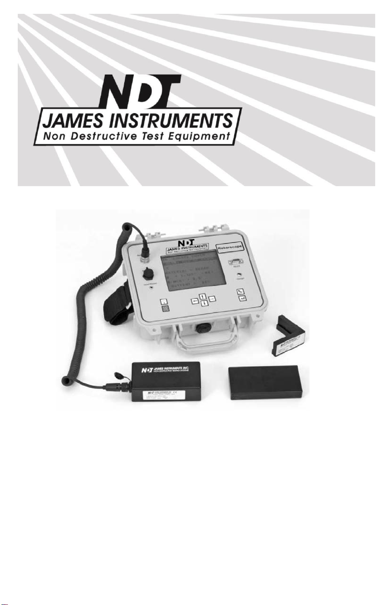
The James® Instruments Rebarscope® utilizes the latest in eddy
current sensing and micro-processor technology to accurately
locate, determine the depth of, and estimate the size of metal
objects in concrete. The eddy current sensor is specifically
designed to react to the outer surface of the metal object only. It is
uninfluenced by small particles in the concrete, whether the
concrete is fresh or hardened, wet or dry.
The Rebarscope® has built-in test modes for rebar/post tension
cable, conduit and copper pipe. The sensor allows the unit to locate
both ferrous and nonferrous metals in concrete.
With an easy to view display, the Rebarscope® provides the user
with an instantaneous structural analysis. The user is aided by
using a graphic bar in the display, and an audio tone to quickly and
accurately locate metal objects. Large numbers in the display show
the estimate of cover. This information can then be used to display
a map of the cover throughout the structure. Further options allow a
2-dimensional cross-section of the concrete under test.
The Rebarscope® was developed for real world application and
everyday durability in mind. It’s rugged and splash resistant case
allows the user to use the Rebarscope® in the field. It’s small but
sturdy sensing probe can withstand test after test with little wear on
the probe face. Additionally, the Rebarscope® is able to
compensate the sensor signal for a wide temperature range; as
may be seen during in-situ field testing.
The Rebarscope® enables the user to store field test data, and later
upload it to a Personal Computer. Once downloaded, the software
allows the user to analyze the data, while a graphing tool function
allows the creation of a contour map.
www.ndtJames.com
1
Page 7

Data Logger Unit
The data logger unit is a standard with the James® Instruments
Rebarscope®. It is a sophisticated, rugged field proven unit. The
embedded microprocessor technology enables the user to easily
locate, determine the amount of cover, record, and analyze ferrous
and non- ferrous metals.
The large easy to read numbers on the data logger display make
the Rebarscope® user friendly when estimating cover or bar
size.
Plus, with a memory capacity of 8000 data points, the data
logger
allows for a large sum of data to be stored for later
analysis.
The front panel of the data logger unit allows the user to interface
with the sensor probe, scan cart, headphones, charger and a
personal computer via a USB port. The large viewing window
protects the LCD display from possible damages that may occur
during operation. Additionally, large control buttons on the front
panel enable the user to easily scroll through menu options.
www.ndtJames.com
2
Page 8
e
Instrument Contents List
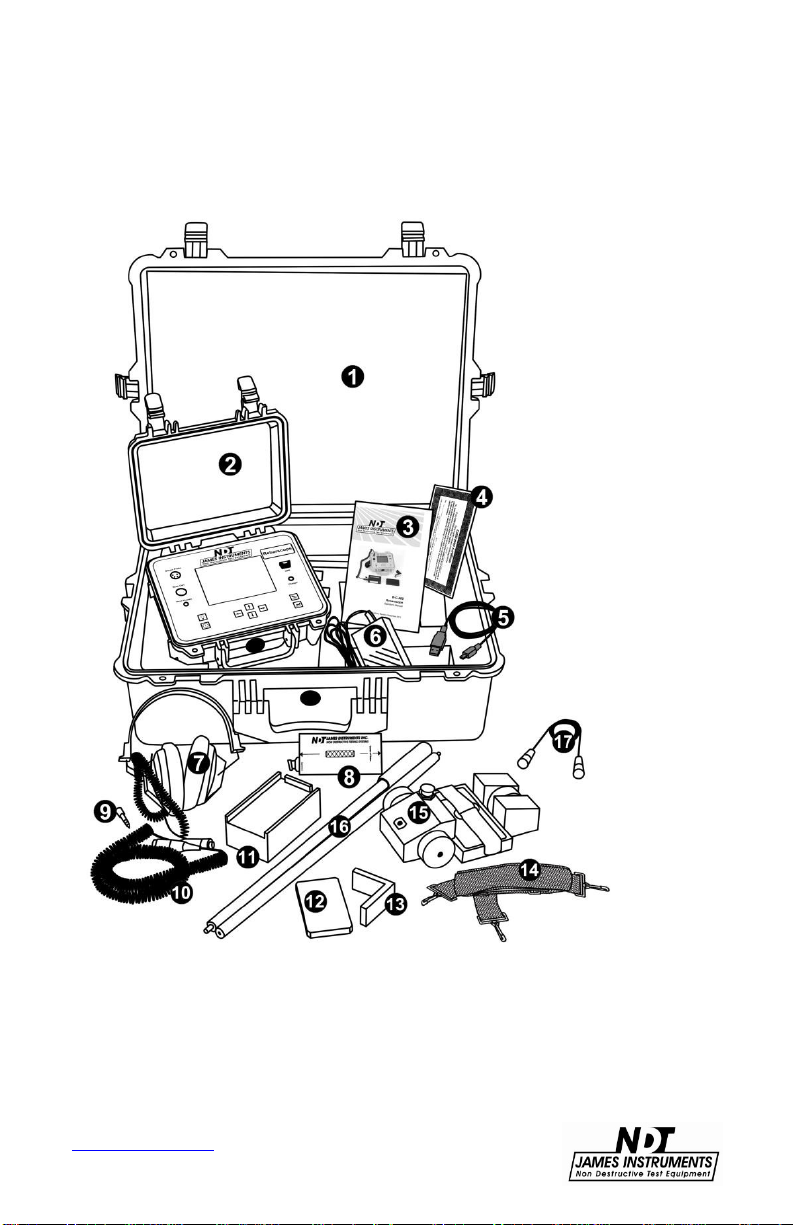
Each Rebarscope® comes with the following items included in the
carrying case.
Figure 1: Rebarscop
®
System Contents
3
www.ndtJames.com
Page 9

Contents List
Item # Description
Case – Used for carrying the Rebarscope®
1
and
Rebarscope® Instrument – Rebar locator encased
2
a durable protective case.
in
accessories.
3
Instruction Manual – Operating instructions for
Rebarscope®.
4
Calibration Certificate – Certificate to confirm that the
instrument has been calibrated to meet or exceed
published specifications.
5
USB Cable – Serial cord used to connect the
Rebarscope® to a PC to upload data.
AC Power Adapter – Used to power the Rebarscope®
6
and recharge the unit.
7 Headphones – Used in noisy environments.
8 Sensor Probe – Shows direction of rebar.
9 Phone Jack – For headset.
10 8’ Coiled Cable – Used with the Sensor Probe.
11 1 5/8” Spacer Block – Used to add space in lower
cover situations.
12 3/8” Spacer Block – Used for sizing feature.
13 Locating Template – Used for sizing feature.
14
Support Strap – Used to secure the Rebarscope®
the user during testing.
to
15 Scan Cart – (opt.) Comes with Complete system only.
16 Scan Cart Extension Poles – (opt.) Used to guide
Scan Cart
17 Scan Cart Cable – (opt.) Yellow cable used to connect
Scan Cart to main unit.
4
www.ndtJames.com
Page 10
Control Panel
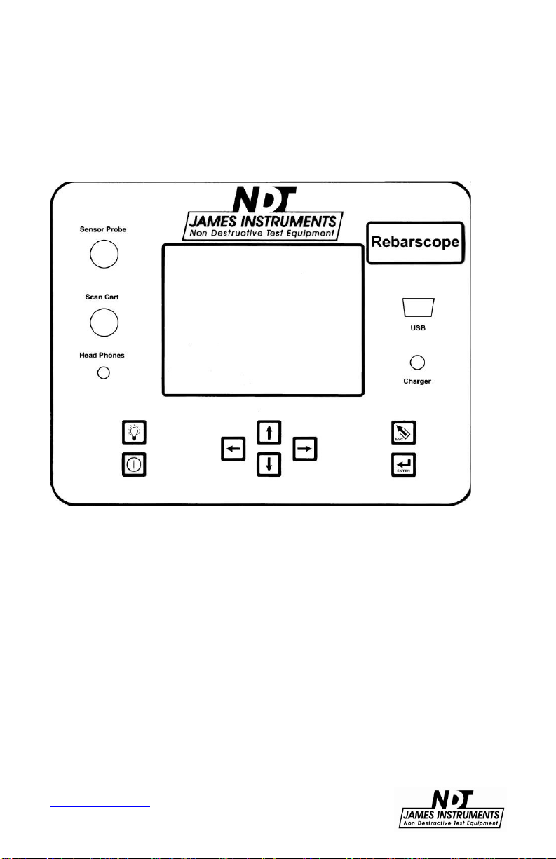
The following buttons appear on the James® Instruments
Rebarscope® System.
www.ndtJames.com
Figure 2: Rebarscope® System Buttons
5
Page 11
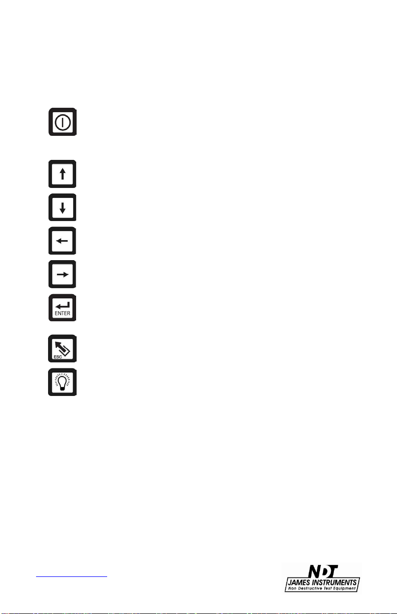
Control Panel Buttons
Key Definition
The power button. Momentarily push this key to turn
“on” the unit. Pressing it again turns off the unit. Upon
power up, the unit will display the locate screen. Press
the escape key to get to the Main Menu.
The up arrow button. This key is used to scroll through
various settings and wave frames.
The down arrow button. This key is used to scroll
through various settings.
The left arrow button. This key allows you to scroll
through various settings.
The right arrow button. This key allows you to scroll
through various settings.
The enter button. Pressing this key allows you to
choose main menu selections. The enter key also
allows you to prepare the Rebarscope® for operation.
The escape button. Pressing this key allows you to
return to the main menu screen from any sub screen.
The back light button. Depressing this key the backlight
of the display comes on. Depressing the key again
turns the backlight off.
www.ndtJames.com
6
Page 12
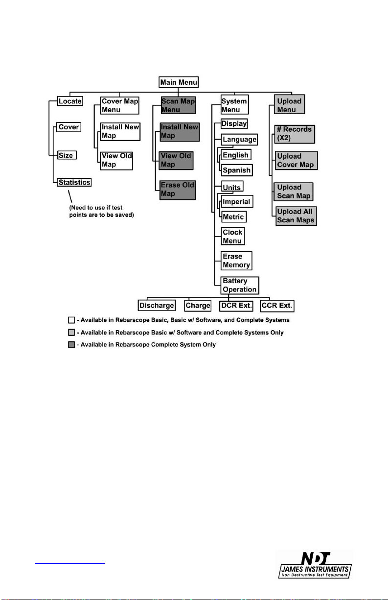
Menu Layout
www.ndtJames.com
Figure 3: Rebarscope
7
®
Function Flow Chart
Page 13

For Quick Reference, in “LOCATE COVER” screen:
1.
For Automatic (RS), Short or Deep mode, go to line
and press the Left arrow button to change
between settings.
2.
For Audio Feature – go to and press the
Right arrow button once for beeps, twice for continuous
tone, and three times for audio off.
3.
Material Options – Rebar (Post Tension Cable) / Conduit /
Copper.
System Menu
Using the Rebarscope® on Location
Removing the Lid
For ease of use in the field, the Rebarscope® lid can be
removed
the lid and
and the shoulder straps installed. To do so, fully open
the cover can be carefully pushed off of the case
hinge pins.
Attaching the Shoulder Support Straps
The Rebarscope® support straps can be used to hold the
Rebarscope® once the Rebarscope® lid has been removed.
When
using the Rebarscope® support straps, make sure that an
eyelet
hook is connected to each corner of the Rebarscope® .
Two of the
around the hinge
hooks clip to the O-rings, while the other two clip
pins.
Follow the step below:
1.
Attach the straight portion of the support strap to the
front metal O-rings of the Rebarscope®.
two
2.
Attach the other two straps (which are stitched to the
straight portion of the harness) to the new exposed
hinges
3.
Pull the supplied support strap over your head so that
rubber guard is resting on the back of the user’s
the
neck.
www.ndtJames.com
of the case.
8
Page 14

4.
Now adjust the strap accordingly so that the
Rebarscope® is within easy reach and readable. (see
Figure 4)
Figure 4: Rebarscope® Support Strap
www.ndtJames.com
9
Page 15

Sensor Probe
The James® Instruments Rebarscope® utilizes the latest in eddy
current sensing technology. The heart of this technology can be
found in the sensor probe which has been specifically designed to
react to the outer surface of metal objects. With this ability, the unit
is able to accurately locate, determine the depth of, and estimate
the size of metal objects within reinforced concrete structures. This
makes the Rebarscope® sensor probe far superior to other
commercially available rebar location systems.
The Rebarscope® sensing probe is compact, weighing only 1 lb
dimensioned at 5”x 2.4”x1.6” and still very tough and durable
and
field application. The sensing probe has been calibrated in our
for
facility for operation with only the data logger unit it was purchased
with. If a new sensor probe is needed it is recommended to send
the complete unit in for proper calibration. Not calibrating the
sensor
unacceptable
information
office.
probe and the data logger unit together can cause
location, cover and bar size readings. For further
regarding repair and calibration please contact our
www.ndtJames.com
10
Page 16
Short / Deep Mode
The Rebarscope® facilitates the analysis of rebar location, cover
and bar sizing; allowing the user to do measurements in short mode
or deep mode. The Rebarscope® also provides the user the ability
to automatically switch between deep and/or short mode.
Note: The single sensing probe operates efficiently in both modes.
When the system is initially turned “on”, the Automatic (RS) mode is
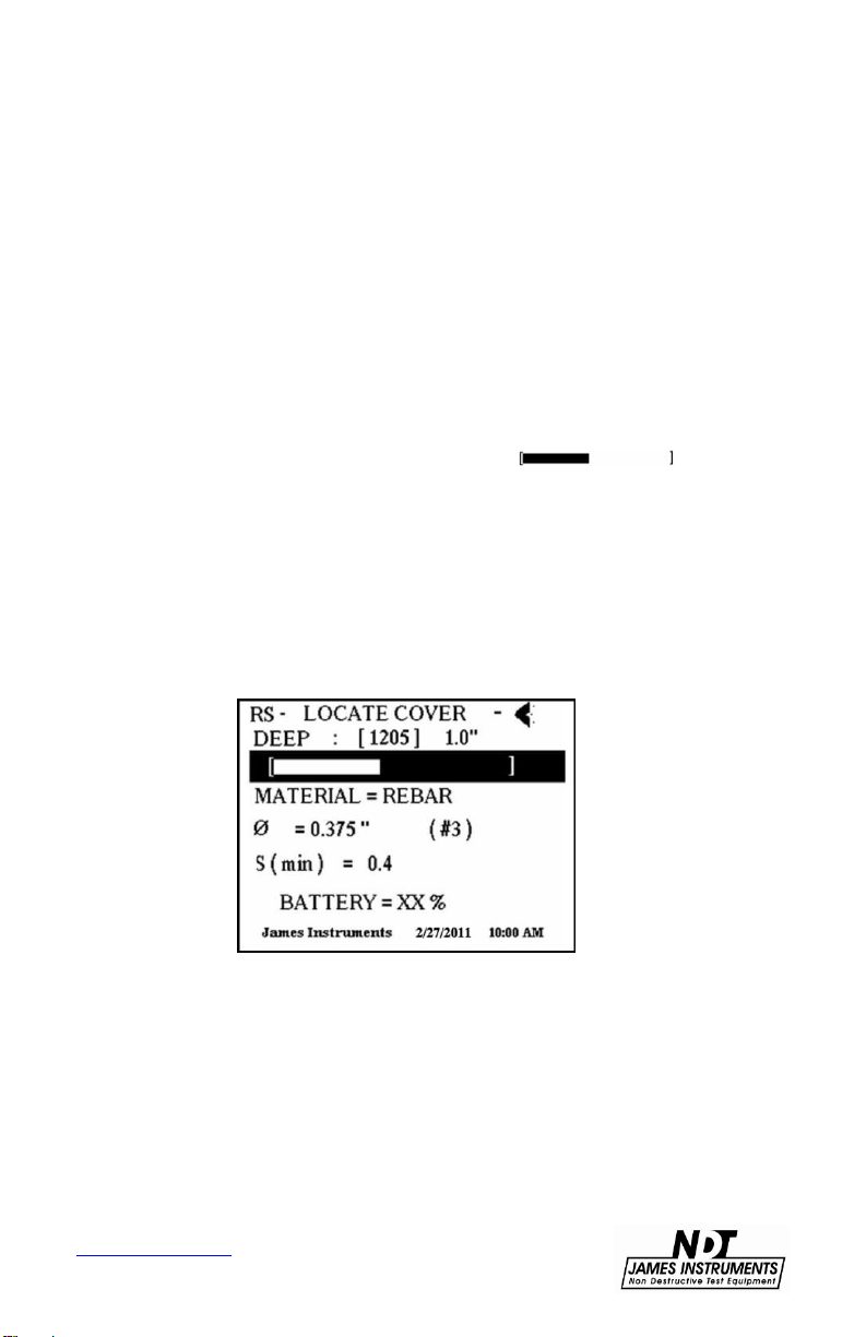
the default setting. To change this, go to the Locate Cover screen.
•
Once in the Locate Cover screen, use the up or down arrow keys
on the front panel to highlight the graphic bar .
•
When the highlight is on the bar, press the left arrow key to
change between modes. (Note: The letters RS in the upper left
hand corner of the screen indicate auto ranging is “on”.)
•
Follow the procedure above to turn off Auto ranging, and to
manually switch between Deep and Short modes as seen on line 1
of this screen.
www.ndtJames.com
Figure 5: Locate Cover Screen
11
Page 17
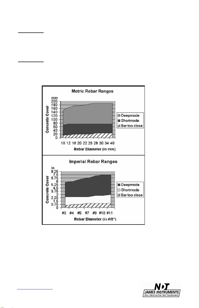
Short mode: Ideal when reinforcement cover ranges from .5” to
3.0”. Locating, determining cover and bar size can all be measured
while in this mode. An error of ± .125” must be accounted for during
measurement of metal bar or pipe location.
Deep mode: Ideal when reinforcement cover ranges from 2.75” to
8”. Locating, determining cover and bar size can all be measured
while in this mode. An error of ± .125” must be accounted for during
measurement of metal bar or pipe location.
Figure 6: Metric and Imperial Graphs for Rebar Ranges
www.ndtJames.com
12
Page 18

Locating Ferrous and Non-Ferrous Metals
The Rebarscope® uses eddy current sensing and micro-processing
technology, and is ideal for locating ferrous and non-ferrous metals.
Metals located with ease are the following:
•
Imperial and Metric reinforcement bars
•
Standard copper pipe
•
Standard conduit pipe
•
Post tension cable (use Rebar mode)
The Rebarscope® allows the user to locate metals by using two
options on the LCD display.
Option 1 – Graphic Bar Display
The action bar displayed on the second line of the location screen
enables the user to determine when the center of the metal bar/pipe
has been detected. When the sensor probe is directly over the
center of the metal bar/pipe, this bar display will have reached its
highest point. When the sensor probe has passed the center of the
metal bar/pipe, the bar display will decrease in size.
Option 2 – Number Display
This option consists of a numerical output value in brackets
displayed on line 1 of the locate cover screen. The range of this
number is 0 to 4095. As the probe moves toward the rebar/pipe the
number will increase. Then when the probe is over the center of the
rebar/pipe you will see the largest number displayed. As you move
the probe away from the center of the rebar/pipe the number will
begin to decrease.
This technique can also be useful in determining whether short or
deep mode is necessary for proper location, cover, and sizing
analysis.
www.ndtJames.com
13
Page 19
Determining Cover
The Rebarscope® allows the operator to easily determine the
concrete cover of rebar. Since the Rebarscope® utilizes eddy
current technology, cover is determined with even more accuracy
than its predecessor. With this, only the bar/pipe is located and no
small particles of metals (such as fly ash) in the concrete can
influence the measurement. The following steps allow for proper
cover measurements:
Step 1: Choose either Imperial or Metric units on the system menu
screen.
Step 2: Decide whether short or deep mode is necessary for your
testing. If needing to adjust this setting, go to the Locate Cover
screen and follow the steps.
Figure 7: Locate Cover Screen
www.ndtJames.com
14
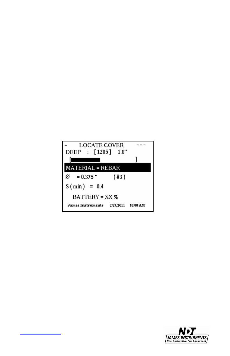
Page 20
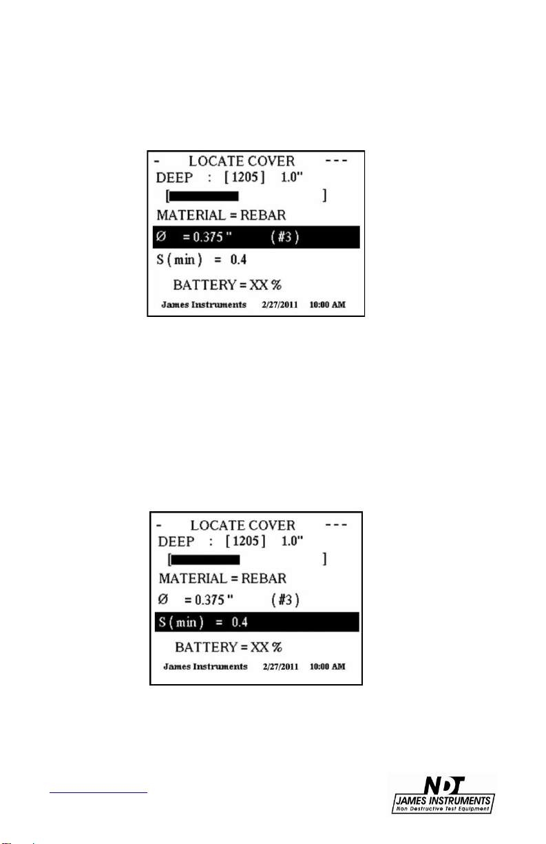
Step 3: Using the down arrow key, scroll the highlighted section
down to the bar diameter category. Once this line is highlighted,
use the right or left arrow keys to choose the proper bar diameter.
Figure 8: Choosing Bar Diameter
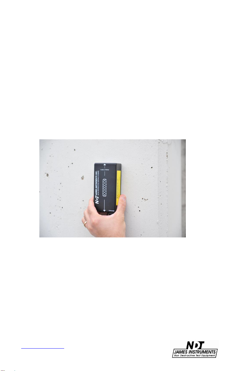
Step 4: Now, pass the sensing probe on the surface of the test
structure until the smallest cover is displayed on the right hand
corner of the screen.
Step 5: The Rebarscope® allows the user to choose the minimum
cover to analyze with. This feature is referred to as the S min. Using
the up or down arrow key, scroll the highlighter down to the S min
category and use the left or right arrow keys to choose an S min that
ranges from 0.4 - 5.0.
www.ndtJames.com
Figure 9: Setting Minimum Cover
15
Page 21

Step 6: Now pass the sensing probe on the surface of the test
structure until the smallest cover is displayed on the right hand
corner of the screen. The audio/ headphone feature also allows
user to precisely locate the center of the rebar using the audio
the
signal. This audio feature helps give even more cover precision.
The steps below show how to properly choose the audio signal for
your application.
Figure 10: Dynamic Bar Display
Step 6A: In the Locate Cover screen, use the up / down arrow
to scroll the cursor down to the action bar in the display.
keys
Step 6B: Use the right arrow key to choose either a beeping type
audio signal, or a continuous tone audio signal. A small speaker
icon will appear on the upper right hand corner of the display when
the audio feature has been enabled. Headphones have also been
supplied with the Rebarscope® to help the user hear a clearer
audio
signal in noisy environments.
Step 6C: Pressing the right arrow key one more time after the
continuous tone will turn off the audio feature, and the speaker
on the upper right hand corner will no longer appear on the
icon
display
screen.
16
www.ndtJames.com
Page 22
Determining Bar Size
The bar diameter can be easily determined with the Rebarscope®
without the prior knowledge of cover. This is possible by taking two
readings, one at surface of the structure and another at the same
location but 3/8 inches away. A 3/8 inch spacer block is provided
with the system along with a locating template. This L shaped
template helps keep the exact location of the first reading when
taking the second reading with the 3/8 inch spacer block (see
pictures below).
(Note: Bar sizing is done in Deep mode only, and at a maximum
depth of approximately 4.5 inches.)
www.ndtJames.com
Figure 11: Locating Rebar
17
Page 23
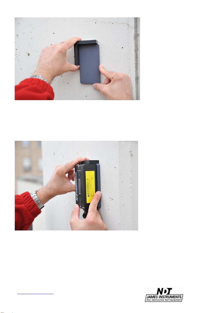
Figure 12: 3/8” Spacer with L Shaped Template
Figure 13: Locating Rebar with Spacer
www.ndtJames.com
18
Page 24

www.ndtJames.com
Figure 14: Analyzing Data
19
Page 25

If the unit shows out of range in the BAR SIZE screen, and the
display reading is 3000 or larger, this means the rebar is too close
to the surface. The first reading should then be taken with the
supplementary 1 5/8” spacer block, and the second with a 3/8”
spacer block. See pictures below. (The supplement spacer block is
used only to add space between the surface and the sensor probe.
It’s size is not critical when performing the sizing function.)
www.ndtJames.com
Figure 15: 1 5/8” Block
Figure 16: 3/8” Block
20
Page 26

The following steps allow for proper bar sizing measurements:
Step 1: Press ESC to exit the Locate Cover screen.
Step 2: In the Main menu screen use the up or down arrow keys to
navigate the highlight to the Locate category.
Figure 17: Bar Size Function
Step 3: Press the right arrow key on the front panel to choose
Locate: Size and press Enter.
Step 4: In the BAR SIZE screen, use the sensor probe to locate the
center of the rebar either by using the bar display or the numerical
output value in brackets [ ].
Figure 18: Bar Size Screen
www.ndtJames.com
21
Page 27

Step 5: Place the sensor on top of the surface where the rebar
diameter is to be measured. If the reading on the first line is larger
than 3000, use the 1 5/8 inches spacer block between the concrete
surface and the sensor. If reading is still above 3000 it may be
necessary to add an additional non-metallic block underneath the 1
5/8 block. (Note: The optimal cover range for sizing is between 1.7”
and 4.2”. Also, the most accurate sizing of rebar occurs when the
first measurement is about 1200.)
Step 6: Once the center has been determined, press Enter for a
few seconds to store the result.
Step 7: The Rebarscope® will now read ADD BLOCK PRESS ENT
on the top line.
Figure 19: Add Block is displayed
At this point the locating template needs to be placed alongside of
the sensor probe; so the exact location of the first reading can be
kept. Note: Taking the second reading at the exact location as the
first is critical for precision. While holding the locating template,
remove the sensor probe and place the 3/8 inch spacer block along
the locating template.
Step 8: Now place the sensing probe over the 3/8 inch spacer block
and press Enter. The Rebarscope® will now display the estimated
diameter of the measured rebar. The Rebarscope® can accurately
determine bar size up to a cover of 4.5" (115mm) in Deep mode.
22
www.ndtJames.com
Page 28

Figure 20: Estimated Diameter is Displayed
Rebar Sizing Guidelines
1. Sizing is done in Deep Mode only, and to a maximum depth of 4.5
inches (~114mm).
2. If the Rebar is too close to the surface (< 2.5 inches), use the 1_5/8”
plastic spacer block (or some wood) to raise the sensor off the surface.
(Rebar Size is best determined when the cover is between 2.5 - 4.5
inches.)
3. Sizing is also best determined when the rebar is isolated - no metal
objects are near the sensor - including the main unit. This may require the
user to move the main unit away from the sensor when testing for rebar
size.
4. Sizing can be done when the rebar “on-center” spacing is equal to, or
greater than 6 inches (~150mm) from any adjacent rebar, conduit pipe,
copper pipe, post tension cable and wire mesh.
5. Sizing accuracy is +/- 1 Bar size for Imperial rebar, and ~ 3mm for
Metric rebar sizes. This variance is due to the physical appearance of
rebar, which has ribs (or ridges) along the length of the reinforcement
bars. It is also due to the program settings of the unit itself. (Imperial
sizes: 3, 4, 5, 6, 7, 9 & 11. Metric sizes: 6, 10, 13, 16, 19, 22, 25, 29, 32,
35, 38, 41 & 51mm.)
6. Due to the high concentration (and/or close proximity) of rebar within a
Column, sizing (and location) is nearly impossible for a Column. It
is not recommended to use the rebar locator for testing Columns.
www.ndtJames.com
23
Page 29

Pitch & Resolution
Measurements can often be influenced by neighboring parallel
bar(s). The graph below shows the minimum spacing to a
corresponding bar.
www.ndtJames.com
Figure 21: Minimum Bar Spacing
24
Page 30

Utilizing Cover Map Function
The James® Instruments Rebarscope® has incorporated a user
friendly cover map to further assist in field analysis. The cover map
mode allows the user to mark the cover and location of a rebar on a
grid. The grid lines are numerically numbered with the Y axis
starting at 1 from left to right. The X axis is also numerically
numbered with number 1 starting at the top of the grid.
The Three symbols below have been selected to allow the user to
distinguish the status of the current reading. A full shaded box
represents that the cover is less than the selected S min. The S min
is the selected minimum cover you have told the Rebarscope® to
detect. A box with 3 thick shaded lines means that the cover is
within range of the selected S min. A box with 3 thin inner lines
means that the Rebarscope® has not detected a bar/tube.
Figure 22: Cover Map Symbols
Please follow this procedure to correctly prepare the Rebarscope®
for Cover Map operations:
25
www.ndtJames.com
Page 31

Step 1: Press the escape key on the front panel to get to the Main
Menu screen.
Figure 23: Cover Function
Step 2: Navigate the highlighted cursor using the up or down arrow
keys to COVER MAP MENU option and press Enter.
Figure 24: Cover Map Menu
www.ndtJames.com
26
Page 32

Step 3: Choose whether you would like to INSTALL NEW MAP or
VIEW OLD MAP by highlighting one and pressing Enter.
Figure 25: Install New Map or View Old Map
Step 4: If View Old Map is chosen please proceed to step 4B, if not
please follow the instruction directly below for installation of a new
map.
Figure 26: Map Display
Step 4A:
1
The Rebarscope® automatically generates a map number.
2
Under the Material category line, choose the material under
investigation. (rebar, conduit, copper)
3.
Choose the diameter of the material under investigation.
4.
Choose the S min (minimum cover)
27
www.ndtJames.com
Page 33

5.
Choose the detection range DEEP or SHORT, that the cover
analysis will be done in.
6.
Press Enter.
7.
The screen now displays the cover map grid.
Step 4B:
1.
After choosing to view old map a REVIEW COVER MAP menu
screen will appear.
2.
The system does not allow adjustment of previous set
Figure 27: Review Cover Map Screen
parameters.
3.
The only function that can be changed is that of which map to
view.
4.
Choose the map number to view and press Enter.
5.
The screen now displays the cover map grid with previously
saved data. New data can be saved into the gridded map along
with the older data.
28
www.ndtJames.com
Page 34

Step 5: Utilizing the Up or Down arrow keys on the front panel
chose the location for your first mark.
Step 6: Pass the sensor probe over the area being investigated; the
blinking cursor will turn into one of the three cover symbols.
Step 7: Pressing the Enter key will save that symbol onto the
screen and store into memory the location information seen on the
bottom of the screen. This information will also appear for this
particular point on the upload screen of the PC software.
www.ndtJames.com
29
Page 35

System Menu
The system setup option on the main menu screen allows you to
make modifications to system configurations. Once in the system
setup sub menu modification can be made to the following
•
Display
•
Language
•
Units
•
Clock menu
•
Erase Memory
•
Battery operation
•
Pressing the escape key takes you back to the main menu screen
Display Cursor
To change the visibility of the display cursor, follow these steps:
•
Press the up or down key until you get to the system setup menu
option. Press Enter. The Setup Menu sub screen should appear.
•
Scroll through the Setup menu using the up or down arrow key.
Select the Display option by pressing Enter. The display should
read the following.
DISPLAY= Black Lines
•
Pressing the left or right arrow keys will give the user the option to
choose Black (highlighted) Lines or White (highlighted) Lines, as
well as the background color.
www.ndtJames.com
30
Page 36

•
Pressing the Escape key will return you to the Main Menu Screen.
Figure 28: Display with Black or White Lines
Language Options
To choose which Language the Rebarscope® will be operating in,
follow these steps:
•
Press the up or down key until you get to the system setup menu
option. Press Enter. The Setup Menu sub screen should appear.
•
Scroll through the Setup menu using the up or down arrow key.
Select the Language menu option by pressing Enter. The display
should read the following.
LANGUAGE=
•
Use the left or right arrow keys to choose English or Spanish as
the language that your Rebarscope® operates in.
Figure 29: Setting the Language
•
Pressing the Escape key will return you to the Main Menu Screen.
31
www.ndtJames.com
Page 37

Measuring Units
English and Metric units are available for the user to choose from.
The following steps allow the user to choose the measuring units
viewed:
Step 1: In the main menu screen use the up or down arrow keys on
the front panel to navigate down to the system set up category.
Step 2: Press Enter.
Step 3: In the system setup screen use the up or down arrow keys
on the front panel to navigate down to the UNITS category.
Step 4: Use the right arrow key to choose either Imperial (English)
or metric measuring units.
Figure 30: Setting the Units
Step 5: Press the ESC key to go back to the main menu screen
and continue measurements.
Clock Menu
To change date and time, please follow these steps:
•
Press the up or down key until you get to the setup menu option.
Press Enter. The Setup Menu sub screen should appear.
32
www.ndtJames.com
Page 38

Figure 31: Clock Menu is Highlighted
•
Scroll through the Setup menu using the up or down arrow keys.
Select the Clock Menu option by pressing Enter. The display should
be similar to the following.
•
Pressing the left or right arrow key will increment the digits on the
Figure 32: Setting the Date and Time
display.
•
Use the up and down key to select each hour and date options.
•
Scroll to the save changes option using the up or down arrow key.
www.ndtJames.com
33
Page 39

•
Pressing the Enter key will store the date and time and return you
Figure 33: Save Changes When Finished
to the Main menu screen.
Erase Memory
To erase stored memory from the Rebarscope®, follow these steps:
•
Press the up or down keys until you get to the system setup menu
option. Press Enter. The Setup Menu sub screen should appear.
SETUP MENU
•
Scroll through the Setup menu using the up or down arrow key.
Select the Erase Memory option by pressing Enter. The display
should read the following.
ERASE MEMORY
•
Press Enter once and a message telling you to press Enter again
to verify this action should appear.
PRESS ENTER AGAIN
•
Pressing Enter a second time will erase ALL stored memory in
the Rebarscope® system. When complete, the phrase “Ø errors”
should be seen on the display screen.
•
Pressing the Escape key will return you to the Main Menu Screen.
www.ndtJames.com
34
Page 40

Battery Operation
The Rebarscope® uses a 14.4V Lithium-Ion battery with a built-in
thermo-sensing circuit. This circuit allows for a suitable charge, and
maintains the voltage to the cells (< 4.1V). Additionally, this circuit
provides the proper charge current to lengthen the battery’s life.
At full charge, the bottom of the display will show BATTERY=100%.
(Note: This value may be inaccurate, if the battery counters were
reset without properly charging the unit.)
-
The battery status can be viewed in the “System Menu”,
under the “Battery Operation” mode. (Fig.34 & 35)
-
When the charger is supplying power to the unit, the battery is
charging, and the charge counter (“Charge CTR”) will increase.
-
When the unit is ON, and the charger is disconnected from the
unit, the discharge counter (“Discharge CTR”) will increase.
-
The battery will continue to charge even after the microcontroller
times out - display and unit turn OFF automatically.
-
When the mode is set to any of the following settings: LocateCover, Size, Statistic, or Cover Map (or Scan Cart for R-C-410)
the charge operation is disabled.
www.ndtJames.com
Figure 34: Battery Operation Menu is Highlighted
35
Page 41

-- BATTERY STATUS-DISCHARGE CTR = xxxx
CHARGE CTR = xxxx
DCR EXT = 0
CCR EXT = 0
Hit ENT to Clear Reg
BATTERY = 100%
Figure 35: Clearing Charger Register
Battery Charge:
1.
Connect the charger to a working outlet, and then to the charger
input on the unit’s front panel. Although, it is recommended for the
unit to be OFF during a charge, the user can monitor the charging
process in the screen above.
2.
If the Charge counter slows to a stop (and does not increase),
this is an indication the charge is complete. The battery now has a
full charge, and needs to be reset. To do this, go to: Main Menu /
System Menu / Battery Operation - press “Enter” to zero the
counters. This action also resets the battery circuit mentioned
above, and will correct any miscounts. (If charging is still an issue,
review the Troubleshooting section on p.57.)
Resetting the battery counters should be done both before and after (at least) a 4hr charge.
When done so, the battery status % on the display will be accurate.
3.
When the Battery percentage reaches ~ 40-50%, be sure to
charge the unit again. (Go to step 1)
4.
A charged battery allows for 4-6 hours of continuous field testing.
5.
To extend the battery’s run time in the field, to turn “OFF” the
background light.
www.ndtJames.com
36
Page 42

Simple Guidelines for Battery Maintenance.
1.
When allowed to discharge and charge regularly, the end user
will experience a better Battery life span (or cycle).
2.
Lithium-ion batteries do not need to be fully charged; as the
charger can aid its performance.
3.
Shallow discharges provide more cycles than deep discharges.
4.
It is recommended to fully charge the unit (4-6hrs) before a
lengthy field test is performed.
5.
As a general rule, it is best to charge the battery both before and
after each use. There is no memory effect, so it is a good practice to
recharge the unit after each use, or at the end of the day - if used
daily.
6.
Charge the battery at a moderate temperature. Do not charge
below 0deg C (or < 32deg F).
7.
Lithium-Ion batteries suffer from stress when exposed to heat.
Therefore, to lengthen the life of the battery, avoid elevated
temperatures > 30deg C (or > 86deg F).
8.
Lithium-Ion batteries may fail when stored for long periods of
time in a discharged state. Thus, before a prolonged storage
period, be sure to apply a charge to the battery. It's recommended
once every 2 months to recharge the battery to keep it fresh. You
should store the Unit (and battery) during this period at room
temperature.
9.
Replacing or repair of the battery should be done by a trained
James® Instruments technician. Please follow the repair
procedure
found on page 68.
www.ndtJames.com
37
Page 43

Scan Cart (R-C-410 Only)
The Rebarscope® Scan cart feature allows the end user to quickly
and easily determine the location and cover of reinforcement in a
concrete structure. The scan cart can be used in a vertical or
horizontal position. The B-Scan diagram generated by the
Rebarscope® facilitates cover readings of a specified rebar.
The following steps allow for proper scan cart application:
Step 1: Insert Rebarscope® probe in scan cart unit with company
logo facing up.
Step 2: Connect scan cart cable (yellow) to front panel of
Rebarscope® unit and scan cart back cover.
Step 3: Turn Rebarscope® and allow unit to initialize.
Step 4: Upon initialization unit defaults to Locate cover screen.
Step 5: Press Esc key.
Step 6: Rebarscope® will now go to the main menu screen. Using
the up or down arrow to highlight the Scan Map Menu.
Step 7: Press Enter
www.ndtJames.com
Figure 36: Highlighted Scan Map Menu
38
Page 44

Step 8: The Scan Map Menu screen will now appear
Figure 37: Scan Map Menu
Step 9: Using the up or down arrow keys navigate the highlighted
line to one of the three sections on the scan map menu screen.
Step 10: Press Enter.
Step 11: The next screen allows you to enter your parameters.
After choosing desired parameters press Enter.
Figure 38: Scan Map Parameters
Step 12: The Rebarscope® now displays the scan cart diagram
screen.
www.ndtJames.com
39
Page 45

Figure 39: Scan Cart Diagram
Step 13: Position scan cart at beginning of area to be analyzed.
Step 14: Press Enter on Rebarscope® Front Panel. The display will
read “Scanner is ON”, and the user is ready to start testing.
now
Step 15: Measuring from the front of the scan cart, begin pushing
the cart at a very slow pace from the starting point; using the
extended handle. (See picture below.)
Step 16: Remain at this same pace until Rebarscope® notifies the
end of scan by producing an end beep noise.
Step 17: The Rebarscope® does not present real time data of a
scan, it is necessary to back the cursor toward the start point to
view data. The results will be displayed in a B-Scan diagram.
www.ndtJames.com
40
Page 46

Figure 40: Scan Map Graph
The scan cart B-Scan diagram can be translated as follows:
•
Cover is represented on the left axis.
•
Distance measured is represented on the top axis.
•
The two dotted lines represent the predetermined setting for Smin.
•
The waveform will start at distance zero and it will be at its lowest
cover reading.
•
As the electro- magnetic decay of the reinforcement bar is
detected by the probe, the built in B-scan analyzer starts to graph
every point of detected cover by its built correlation.
•
Once the scan cart with inserted probe is above the center of a
section of rebar the wave form will be displayed at its top peak.
•
After the scan cart has moved past the center of the rebar a very
noticeable downward decay will begin to display. The wave form
will remain at its lowest possible cover until another rebar’s
electromagnetic decay can be detected by the scan cart.
41
www.ndtJames.com
Page 47

Operating System
Data Handler Introduction
The Data Handler allows you to accept uploaded data from
Rebarscope® to the PC
the
Features
•
Easy to Use
•
Quick
•
Convenient
•
Traceability
•
Data Backup
Minimum System Requirements Rebarscope® Data Handler
Windows Vista or Windows 7
Memory
Processor
Capacity
www.ndtJames.com
1 GB RAM
1 GHz Pentium class processor
1 MB hard drive space
42
Page 48

Upload Data (R-C-450 and R-C-410 only)
•
Connect the unit to the appropriate port of the P.C. using the
supplied serial cable.
•
Press the up or down key to advance to the upload menu option.
Figure 41: Upload Menu is Highlighted
Press Enter. The following upload sub screen should appear.
Figure 42: Upload Sub Screen
Scroll through the upload sub menu using the up or down arrow
key. Select which upload menu function you would like to perform
by pressing Enter. The display should read the following:
UPLOAD SCAN MAP (R-C-410 only) UPLOAD ALL SCAN MAPS (R-C-410 only)
www.ndtJames.com
43
Page 49

•
Pressing the left or right arrow key allows the user to select which
number of test data they want uploaded.
•
Open the Rebarscope® software (“Rebarscope” will appear on the
upper left corner) on the P.C.
•
Press the Lightning Bolt (Upload) icon. The P.C. software will
display “waiting for data”.
•
Go to the Rebarscope® and press the Enter key. Rebarscope®
software waits 50 seconds for the upload information. If no data is
received after 50 seconds a “No data received“ sub screen will
appear.
•
During Test upload the displays reads “Upload In Progress”
•
Once the upload has been completed the display will read
“Upload complete” and data will appear on the screen. Save the
data in a desired folder.
•
Pressing the Escape key will return you to the Main Menu screen.
•
After upload, graphing of data should be done with PC software.
•
Press the graph icon to graph the B-Scan diagram on the PC.
www.ndtJames.com
44
Page 50

Data Handler Overview
The following is an overview of all of the features of the Data
Handler software.
Figure 43: Data Handler Overview
Software Functions
Key Definition
The “Open” command (Ctrl+O) – Opens a previously
uploaded text file.
The “Save” command (Ctrl+S) – Saves uploaded data
to a text file.
The “Upload” command (Ctrl+U) – Uploads data from
the Rebarscope to the Data Handler program.
The “Graph Time” command (Ctrl+T) – Graphs the
stored data.
The “3D” command (Ctrl+D) – Graphs the stored data
as 3D.
www.ndtJames.com
45
Page 51

Software Installation
The PC software that has been developed for the Rebarscope is for
data upload purposes. To install the software on your PC follow
these instructions.
To install the software:
1.
Insert the Rebarscope PC Software CD into the CD-ROM
drive.
2.
If the CD does not load the setup automatically, go to My
Computer, double click on the CD under devices and
double click on setup.exe.
3.
The Install Shield Wizard checks for the operating system
Figure 44: Installation File Location
you are using.
www.ndtJames.com
Figure 45: Install Shield Wizard
46
Page 52

4.
The Install Shield Wizard dialog appears. Click Next to
proceed.
5.
Accept the terms in the license agreement and click Next.
Figure 46: Install Shield Wizard
Figure 47: License Agreement Screen
www.ndtJames.com
47
Page 53

6.
Complete the customer information fields and click Next.
Figure 48: Customer Information Screen
www.ndtJames.com
48
Page 54

7.
The Install Shield Wizard confirms your installation. Click
Install to continue.
8.
The installation progress screen appears.
Figure 49: Install Shield Wizard Confirmation
9.
When the installation has completed the following message
will appear. Click Finish to close the dialog.
www.ndtJames.com
Figure 50: Installation Progress Screen
49
Page 55

Figure 51: Install Shield Wizard Completed
The Data Handler shortcut appears on the desktop as well
10.
as the Start Menu.
www.ndtJames.com
Figure 52: Data Handler Shortcut
50
Page 56

Uploading Cover Map (R-C-450 and R-C-410 only)
Uploading a single Cover Map.
a.
On the Rebarscope® display, go to “Upload Menu”.
i.
Figure 53: Main Menu Screen
On the Data Handler Software press the Upload
ii.
Button.
iii.
iv.
On the Rebarscope® display, choose “Upload
Cover
Map”.
Now save the results into the PC.
www.ndtJames.com
51
Page 57

Fig. 54: Rebarscope Data Handler Screen
The display should show the Cover Map as a text.
Fig.55: Data Handler Screen with Text Data
www.ndtJames.com
52
Page 58

b.
Uploading multiple Cover Maps.
On the Rebarscope® display, go to “Upload Menu”.
i.
Fig. 56: Main Menu Screen
ii. On the Data Handler Software press the Upload
Button.
iii.
On the Rebarscope® display, choose “Upload
Cover
Maps”.
iv.
Now save the results into the PC.
Note: The Data Handler Software doesn’t provide graphical
presentation of the Cover Map, as this only done inside the
Rebarscope® software.
To view the cover map data:
-
From open menu or simply press the open button
or press “Ctrl + O”
Then open the required file in the Data
Handle Software.
-
Also it is possible to open the Cover Map
file as text file
it.
simple by double clicking
Fig. 56
www.ndtJames.com
53
Page 59

Uploading Scan Map (R-C-410 only)
c.
Uploading a single Scan Map.
On the Rebarscope® display, go to “Upload Menu”.
i.
Fig. 58: Main Menu Screen
On the Data Handler Software press the Upload
ii.
Button.
On the Rebarscope® display, choose
iii.
“Upload Scan
Now save the results into the PC.
iv.
d.
Uploading multiple Scan Maps.
On the Rebarscope® display, go to “Upload Menu”.
i.
On the Data Handler Software
ii.
press the Upload
On the Rebarscope® display, choose “Upload Scan
iii.
Maps”.
Now save the results into the PC.
iv.
Note: It is essential to move the scan cart at
a slow rate:
bad readings.
(1 inch/sec maximum) to avoid
Map”.
Button.
www.ndtJames.com
54
Page 60

Graphic representation of the Scan Map data
1.
2D representation:
a.
Open a saved Scan Map data.
b.
Press the Graph Time command symbol.
c.
The software will show a 2D representation of
Cover vs. Distance in inches, and it represents
cross section of the location that was crossed
a
the scan cart.
by
www.ndtJames.com
Fig. 59: Graph Window Screen
As shown in the example above (3 foot map), it
shows the existence of a rebar at a distance of 11”
(1.7”cover), 22.7” (1.7” cover) and 36” (0.9” cover).
55
Page 61

2.
3D representation:
The 3D representation helps to show multiple Scan Maps
one graph, to use this feature; first it requires storing
in
several Scan Maps (minimum two).
As shown in the figure to the
by taking several scan
left,
readings,
Scan Maps to
the 3D option will
these maps to generate a
graph showing the peaks that
represents the existence of a
rebar and valleys that
correspond
rebar, also a color
implemented that shows a
rebar in the dark blue area of
the
are in
and upload all the
the computer,
arrange
3D
to absence of
code is
graph and the empty areas
green or orange color.
Fig.60
www.ndtJames.com
56
Page 62

Using the 3D graph option:
a.
Press the 3D command symbol.
b.
Set the Slice number to 1
c.
Browse for the first Scan Map, select it and click
open,
graph space.
d.
Set the Slice number to 2.
e.
Browse for the second Scan Map (usually all Scan
Maps are save in the same location), select it and
open.
click
f.
The graph starts to form, and by adding more slices
graph will expand in the Z-direction.
the
g.
To export the graph, click “Export”.
h.
Choose s suitable format and click Save.
Fig. 61: Graph Window
at this stage nothing will appear on the
www.ndtJames.com
Fig. 62: Graph Window with Export Dialog Screen
57
Page 63

Troubleshooting
The James® Instruments Rebarscope® built in troubleshooting
diagnostics helps the user identify problems with the system. This is
a beneficial tool for the user which may help to resolve the problem
without the need of sending the system “in” for repair. The
troubleshooting diagnostics are the following: (a) Sensor Cable
Problem, (b) Sensor board Problem, (c) White Display, (d)
Battery Charging problems, (e) Uploading Data issues. Follow
the steps below to properly diagnose the 5 problems listed:
(a)
Sensor Cable Problem
Step 1: Check cable connections between sensor and front panel.
Step 2: Check cable connectors for bent or pushed “in” pins. If yes,
the sensor cable problem will appear.
Step 3: Check sensor and front panel connectors. If a pin(s) has
been bent or pushed “in”, the sensor connector cable problem will
appear.
If steps 1 thru 3 do not correct the problem please contact our office
for assistance and possible repair options.
(b)
Sensor Board Problem
Please Contact our Office for repair options.
(c)
White (or blank) Display
This error condition may occur when using the White Line setting of
the Display mode (under System Menu).
In this condition, the Black background becomes White, along with
the letters; thus making the entire screen White. To correct this
issue, try the following steps… (Note: This is a blind operation; until
the end.)
1.
Press the Escape button (x1)
2.
Press the Down button (x2) for Basic systems, and (x3) for
www.ndtJames.com
58
Page 64

Complete systems.
3.
Press the Enter button (x1)
4.
Press the Right (or Left) Arrow button (x1)
When completed, the display should become visible – with Black
letters and a White background. If this does not reset the display
condition, the user should Power cycle the unit “OFF”, and then
back “ON”.
In the event this White Out condition remains, contact James®
Instruments for further repair instructions. (or see Page 70)
(d)
Battery Charging Problems
This condition can happen when the Charge Counters have not
been reset for some time, or… if there is a problem with the battery
itself. (Note: The main battery usually lasts ~ 3-5 years.)
Before sending the unit to James®, try to Reset (or zero) the
battery
System
Charge and
be reset
properly. Also,
status value to
counters in the Battery Status screen. Go to: Main Menu /
Menu / Battery Operations - press “Enter” to reset the
Discharge counters to zero. These counters need to
periodically for the battery monitoring circuit to work
Zeroing these counters will change the battery
100%. This will happen whether or not the unit was
charged.
Therefore, after resetting the counters, charge the unit for at least
4 hours, and reset the counters again. Doing so will provide the
most accurate % status of the battery.
If this does not correct the charging problem, the system will need
to be evaluated further at James® Instruments. (See Repair
Services
in the Calibration & Repair section.)
(e)
Uploading Data Problems
This condition can happen when first attempting to use the
James®
not being
Instruments software on a PC. It is due to the Comports
set to the same setting within the software.
www.ndtJames.com
59
Page 65

To find the correct Comport to use, follow the steps below…
1.
Go to the PC’s Device Manager… Start button / Control Panel /
Device Manager / Ports.
2.
Connect the USB cable to the unit. Then, while viewing the
‘Ports’ directory, connect the USB cable to one of the PC’s USB
ports. The correct Comport setting will become visible in the ‘Ports”
directory.
3.
When the correct Comport is found, go to the James®
software,
the correct
and click on ‘Tools’ in the task bar (at the top). Select
Comport (1-20) from the drop down list.
4.
Go back to the unit and select the Test Data to upload.
5.
Go back again to the software, and click on the Lightning Bolt
icon in the task bar…
6.
Now press ‘Enter’ on the unit to start the upload process. The PC
should say the computer is “Receiving Data”.
If these steps do not work, it is possible the correct Drivers need to
be installed on the PC. Go to the following website for more help…
http://www.ftdichip.com/Drivers/D2XX.htm
(Note: Although James® does not support Windows XP (any
longer),
the data handler should still work with XP.)
60
www.ndtJames.com
Page 66

Maintenance
• If the Main 14.4V Battery does not hold a charge, the
system should come back to James® Instruments for
battery
before
replacement. (Review Troubleshooting section (d)
sending the unit back to James® Instruments.)
• Calibration is recommended to be done annually, or
when
display readings are suspected to be inaccurate.
• Keep the unit clean. If dust builds up in the unit, clean it
out
with compressed air.
Safety
•
Do not submerge unit in water. This can cause
electrical
•
The sensor generates a magnetic field. Do not point
the
fields.
shock.
sensor on products that are sensitive to magnetic
www.ndtJames.com
61
Page 67

Available Rebarscope Accessories
Part # Description
R-C-3015
R-C-3020
R-C-3030
R-C-3031
R-C-3035
R-C-3040
R-C-3051
R-C-3052
R-C-3056
R-C-475
S-31800
Probe
Scan Cart
Coiled Cable
Scan Cart Cable
Headphones
Locating Template
Basic Software
Scanning Software
USB Cable
Scan Cart Upgrade
Charger
www.ndtJames.com
62
Page 68

Specifications
Rebarscope® System R-C-400, R-C-450, R-C-410
Sensor Dimensions 5”L x 2.4” W x 1.6” H
Sensor Weight 1lb
Instrument Dimensions 10.625” L x 9.68” W x 4.875” H
Instrument Weight 5.4
lbs
Complete System Weight 10 lbs
Basic System Weight 8 lbs
LCD Dimension 3.5”L x 4.65“H
LCD Size 320 x 240 pixels
Operating Temperature -10 - 50 C
Covered Rebar Sizes (#) 3, 4, 5, 6, 7, 9, 11
Standard Copper Pipe Sizes .375, .500, .750, 1.00, .1.250
Standard Conduit Sizes .750, 1.00, 1.250
(mm) 6, 10, 13, 16, 19, 25, 29, 32,
35, 38, 41, 51
Power Source 14.4V, 4hr continuous use
63
www.ndtJames.com
Page 69

Warranty Information
1. Contract
Unless otherwise stated all sales transactions are expressly subject to these
terms and conditions. Modification or additions will be recognized only if
accepted in writing by an authorized Officer of James® Instruments Inc.
(hereinafter referred to as “James®” or the “Company”), or an officially
designated representative. PROVISIONS OF BUYER'S PURCHASE ORDER
OR OTHER DOCUMENTS THAT ADD TO OR DIFFER FROM THESE TERMS
AND CONDITIONS ARE EXPRESSLY REJECTED. NO WAIVER OF THESE
TERMS AND CONDITIONS OR ACCEPTANCE OF OTHERS SHALL BE
CONSTRUED AS FAILURE OF THE COMPANY TO RAISE OBJECTIONS.
2. Warranties
The Company only warrants the equipment manufactured or supplied by the
Company as set forth herein. James® makes no other warranties, either
expressed or implied (including without limitation, warranties as to
merchantability or fitness for a particular purpose). In no event shall James®
be liable for any type of special, consequential, incidental, or penal
damages, whether such damages arise out of or are a result of breach of
contract, warranty, negligence, strict liability or otherwise. Warranty shall not
apply where the equipment manufactured or supplied has been subject to
accident, alteration, misuse, abuse, improper storage, packing, force majeure,
improper operation, installation, or servicing. In addition, the following shall
constitute the sole and exclusive remedies of Buyer for any breach by James®
of its warranty hereunder.
a. New Products
James® warrants the equipment manufactured or supplied by
James® as set forth herein. This limited warranty can only be
exercised by the original purchaser of the equipment from James® or
authorized James® Agent and is not transferable to any subsequent
owner or party. This l imited warranty gives you specific legal rights,
and you may also have other rights which vary from case to case.
i. For James® Equipment
James® warrants that James's equipment will be free
from defects in materials and workmanship for a period of
twenty- four (24) months on the electronic portion and six (6)
months on the mechanical portion from the date of shipment
of equipment from James® to Buyer. Should any defects
be found and reported by the Buyer during the applicable
limited warranty period, the defect will be corrected upon
return of the item to James®. James® will, during the
applicable new equipment warranty period, provide the
necessary replacement parts and labor to correct the defect.
Excluded from the new equipment warranty are all
www.ndtJames.com
64
Page 70

www.ndtJames.com
consumable and wear and tear items suc h as impact bodies,
penetrators, connection cables, etc. These items are subject
to usual wear and tear during usage. Refer to the
Consumable, Wear and Tear Items section of this warranty
document.
Option For Extended Limited Warranty Coverage
The original purchaser of any new equipment of James®
which have been identified or labeled by James® from time
to time in James's sole discretion as being eligible for
extended warranty coverage shall have the option to
purchase certain extensions of the applicable limited
warranty provided hereunder to the electronic portion of
any such items for either a twelve (12), twenty-four (24)
or thirty-six (36) month period (up to a possible maximum
limited warranty coverage period for the electronic
portions of such new James® equipment of sixty (60)
months) by purchasing any such twelve (12), twenty-four
(24) or thirty-six (36) month limited warranty extension
period either all the time of the purchase of any such
item(s) or within ninety (90) days from the date of delivery
of the subject item(s) of the original purchaser of such
item(s). The price for each such extended limited warranty
coverage period shall be as determined by the
Company from time to time and all such purchases of
any extended warranty coverage periods shall only be
effective upon a completed purchase order and payment
directly between James® and the original purchaser of any
such item(s). The extended warranty coverage periods
only valid with respect to the original purchaser of
are
such item(s) from the Company and such extended
warranty coverage is not transferable to subsequent
owners of the subject item(s) or any other parties. Upon
the purchase of any extended limited warranty coverage
period, the Company will issue a certificate to Buyer
evidencing the details of the applicable extended warranty
coverage period purchased by the Buyer.
ii. For Other Manufacturer's Products Supplied by
James®
Products of other manufacturers supplied as such by
James® are warranted by James® only to the extent of
any warranty provided by the original manufacturer, if any.
iii. For Parts and Sub-Assemblies
Parts or sub-assemblies purchased by the Buyer to
perform its own repair work etc. are warranted as provided
hereunder by James® for six (6) months from date of
shipment of material from James® to Buyer.
65
Page 71

iv. For Consumables, Wear and Tear Items
James® supplies consumable items and items subject to
wear and tear during normal usage of James® supplied
products. These items are not covered under warranty.
Buyer is to check for proper fit, form and function of such
items upon receipt of such items. In case of a defect
condition, Buyer can return the item to James® for
evaluation within thirty (30) days of the date of shipment to
the Buyer. James® reserves the exclusive right to issue
full, partial, or no credit to the Buyer based on the
condition of the returned item and circumstances related to
the return. Examples of items in this category: connection
cables, test blocks, impact bodies, penetrators, probes,
extraction liquids, calibration liquids, pins, recording paper,
b. Calibration and Repair
test plugs, etc.
i. For Calibration Services
James® does not warrant the calibration of any
equipment. James® does however warrant the equipment
manufactured by it, in proper working condition, to be
capable of being adjusted to meet James® printed
specifications, if any, for accuracy and performance as to
the particular model type during the period of warranty
applicable as stated above.
ii. For Repair Services
James® warrants repair work performed under the direct
control and supervision of James® personnel for a period
of three (3) months from the date repairs are completed
either at James® or at the customer site. Should the def ect
for which the repair work was performed reoccur within
this period, James® will supply the necessary parts and
labor (repair at James® facility) or parts (repair at Buyer
facility) required to repair the original equipment defect for
which the repair parts and labor were required. Additional
repair charges that may be incurred in conjunction with any
repair service warranty event will be invoiced at the
James® customer s ervice rates and policies in effect at the
time of the event.
Excluded are all consumable and wear and tear items such
as impact bodies, probes, connection cables, etc. These
www.ndtJames.com
66
Page 72

items are subject to usual wear and tear during usage. Refer
to the Consumable Wear and Tear Item section of this
warranty document.
www.ndtJames.com
67
Page 73

c. Warranty Claims
i. For Warranty Claim Processing
James® has established James® organizations in the
Americas, and Europe. Please visit the James® web site
www.ndtJames.com for latest address and contact
3. Regulatory Laws a nd/or Standards
The performance of the parties hereto is subject to the applicable laws of
the United States. The Company takes reasonable steps to keep its
products in conformity with various nationally recognized standards and such
regulations, which may affect its products. However, the Company recognizes
that its products are utilized in many regulated applications and that from
time to time standards and regulations are in conflict with each other. The
Company makes no promise or representation that its product will conform to
any federal, provincial, state or local laws, ordinances, regulations, codes or
standards except as particularly specified and agreed upon for compliance in
writing as a part of the contract between Buyer and the Company. The
Company prices can not i nclude the cost of any related inspections or permits
or inspection fees.
information for the James® organization nearest you.
4. Notices
Notice by either the Company or Buyer will be made only by facsimile or
similar electronic transmission, effective on the first business day after
confirmed receipt, or by letter addressed to the) other party at its address as
provided in this Agreement, effective three (3) business days after deposit
with the U.S. Postal Services, postage prepaid, or one (1) business day after
deposit with a recognized overnight express service.
5. Interpretation
Should any term or provision contained In the contract contravene or be
invalid under applicable law, the contract shall not fail by reason thereof but
shall be construed in the same manner as if such term or provision had not
appeared therein.
6. Assignability
Neither this contract nor any claim arising directly or indirectly out of or in
connection herewith shall be assignable by Buyer or by operation of law,
without the prior written consent of Company. This document shall be binding
upon and inure to the benefit of each party hereto and their respective
permitted successors and assigns.
68
www.ndtJames.com
Page 74

7. Governing Law
This Agreement shall be governed by and construed in accordance with the
internal laws of the State of Illinois, without regard to its conflict of laws
provisions. Buyer and the Company expressly agree to submit to the personal
jurisdiction of the federal and/or stale courts silting in Chicago, Illinois, U.S.A.
and agree that such courts may be utilized if necessary to obtain injunctive or
any other relief. The Hague Convention and the United Nations Convention on
Contracts for the International Sale of Goods shall not apply to the construction
or interpretation of these Standard Terms and Conditions or affect any of its
provisions.
END.
www.ndtJames.com
69
Page 75

Repair Policy
United States | Canada | International
Ship the instrument in a box that meets UPS, Fed Ex, and standard
shipping regulations. Enclose a note describing the problem(s) you
are having. Include the name and phone number of the contact
person in your organization.
The instrument will be evaluated within one week of receipt. The
contact person will be notified with an estimate of the cost of the
repair.
Upon receipt of your authorization of repair and payment terms,
delivery time will be 2 weeks from that day.
If you need the repair back sooner than this, you have the option of
paying an express service fee of 10 percent of the purchase price
of said instrument, plus the repair cost. With this service, you can
receive the instrument back within 3 working days in the USA (5
working days for Europe).
International repair shipments must contain a commercial invoice
listing the instrument being returned and must contain the words:
Country of manufacture: USA
Instrument being returned to manufacturer for repair – no value for
customs, value for carriage only.
Ship the complete system to:
Attn: Repair Department
Attn: Repair Department
James Instruments, Inc. - USA
3727 North Kedzie Avenue
Chicago, IL 60618-4503
USA
Home page: www.ndtJames.com
E-mail: info@ndtJames.com
europe@ndtJames.eu
www.ndtJames.com
James Instruments, Inc.
Windmolen 22
7609 NN Almelo
The Netherlands
70
– Europe
Page 76

James Instruments Inc. 3727 N. Kedzie Ave. Chicago, IL 60618-4503 USA Tel: (773) 463-6565 Fax: (773) 463-0009
James Instruments Inc. - Europe Windmolen 22 7609 NN Almelo The Netherlands Tel: +31 (0)548 659032 Fax: +31 (0)548 659010
Purchase Date: ___________________
Serial Number: ___________________
www.ndtJames.com
71
 Loading...