

Page 1
VISCAM 1000 System
Vehicle Imaging Subsystem
Document P/N: 10873
Document Version: C
Page 2

Page 3

Disclaimer iii
VISCAM 1000 Systems
Notice
The material contained in this manual consists of information that is proprietary to JAI Inc., and may only
be used by the purchasers of the product. JAI Inc. makes no warranty for the use of its product and
assumes no responsibility for any errors which may appear or for damages resulting from the use of the
information contained herein. JAI Inc. reserves the right to make changes without notice.
Microsoft Windows 8, Windows 7, Windows XP, Windows 2000, Windows 98, Windows NT, and Windows
Explorer are either registered trademarks or trademarks of Microsoft Corporation in the United States
and/or other countries.
Warranty
Each JAI product is warranted to be free from defects in material and workmanship under normal intended
use and service if installed in accordance with this manual. The standard warranty period for the VISCAM
1000 is 1 year (12 months) and begins on the date of shipment from JAI stock.
This warranty shall not apply to repairs or replacements necessitated by any cause beyond the control of
JAI, including but not limited to, 1) improper installation, 2) acts of nature, 3) accidents, 4) misuse, 5)
lack of proper maintenance, 6) unauthorized repairs or modifications.
Be advised, that you need to obtain an RMA number from JAI before returning units for warranty repair.
Page 4

VISCAM 1000 Systems
iv
Disclaimer
Certifications
CE Compliance
The VISCAM 1000 has been certified to conform to the requirements of Council Directive 89/336/EC for
electromagnetic compatibility and to comply with the following European Standards:
Emissions: EN 55022A: 2010/AC:2011
Immunity: EN 61000-4
All JAI products bearing the CE mark have been declared to be in conformance with the applicable EEC
Council Directives. However, certain factory-installed options or customer-requested modifications may
compromise electromagnetic compatibility and affect CE compliance. Please note that the use of
interconnect cables that are not properly grounded and shielded may affect CE compliance.
Contact JAI Applications Engineering Department for further information regarding CE compliance.
FCC
This equipment has been tested and found to comply with the limits for a Class A digital device, pursuant
to Part 15 of the FCC Rules. These limits are designed to provide reasonable protection against harmful
interference when the equipment is operated in a commercial environment. This equipment generates,
uses and can radiate radio frequency energy and, if not installed and used in accordance with the
instruction manual, may cause harmful interference to radio communications. Operation of this equipment
in a residential area may cause harmful interference, in which case the user will be required to correct the
interference at his own expense.
IP66
This equipment has been tested and found to comply with IP66. This proves that the equipment is resistant
to rain and dust in severe outdoor environments.
WARNING
Changes or modifications to this unit not expressly approved by the party responsible for FCC compliance
could void the user’s authority to operate the equipment.
January 30, 2015
Page 5

Tables of Contents v
VISCAM 1000 Systems
Table of Contents
Disclaimer Notice ..................................................................................................... iii
Table of Contents ...................................................................................................... v
1
Introduction ............................................................................................... 1
1.1
Document Overview ..................................................................................... 1
1.2
Product Overview and System Hardware Components ............................................ 1
1.2.1 VISCAM 1000 System ..................................................................................... 2
1.2.2 External Traffic Light Sensor – TLS-301 (optional) ................................................. 2
1.2.3 External Light Sources .................................................................................. 2
1.2.4 Embedded Light Sources (LED-1000 IR, white or blue) ............................................ 2
1.2.5 VJP-300 Junction Panel ................................................................................. 2
1.2.6 Optional 24V DC Power Supply ........................................................................ 2
1.2.7 Optional gigabit Ethernet switch ..................................................................... 2
1.2.8 System interconnection cables ........................................................................ 2
1.3
VISCAM 1000 Product Line .............................................................................. 3
2
Preparing for installation ............................................................................... 4
2.1
Installation Preparation................................................................................. 4
2.2
Overhead Positioning .................................................................................... 4
2.3
Side of Road Installation ................................................................................ 6
3
Installing the VIS - Vehicle Imaging System ......................................................... 7
3.1
VIS Power Requirements ................................................................................ 7
3.1.1 Installing the VISCAM 1000 System.................................................................... 7
3.2
Installing the VJP-300 Junction Panel ................................................................ 9
3.2.1 Connection to VISCAM 1000 (X1 AND X2) ............................................................ 9
3.2.2 X6 Power Input Connector ........................................................................... 11
3.2.3 Trigger Input Connector (X14) ....................................................................... 11
3.3
Installing the TNL-50 .................................................................................. 12
4
System Set-Up .......................................................................................... 14
4.1
Pre-Alignment Checklist .............................................................................. 14
4.2
Select a Suitable Vehicle, License Plate, and Plate Stand for the Setup .................... 14
4.3
Connect the Setup Computer to the Camera ..................................................... 15
4.4
Drive and Park the Setup Vehicle Correctly ....................................................... 15
4.5
Perform Initial Lens Adjustment and Camera Aiming ........................................... 16
4.6
Perform Final Camera Mount and Lens Adjustments ............................................ 19
4.7
TNL-50 Flash Alignment and settings ............................................................... 21
4.7.1 TNL-50 Flash Settings ................................................................................. 22
4.8
LED-1000 Embedded Illuminator Setup ............................................................ 24
4.9
Trigger Mode Selection ............................................................................... 26
4.9.1 Trigger Synchronization Mode Selection ........................................................... 26
4.10
Automatic Triggering and Light Sensing Configuration .......................................... 27
4.10.1 Vehicle Detector Trigger Settings ................................................................... 27
4.10.2 Visualization helper for Vehicle Detector and ALC setup ....................................... 28
4.10.3 ADR settings in ALC mode ............................................................................ 29
4.11
High Dynamic Range Settings ........................................................................ 30
4.12
Time Synchronization Settings ...................................................................... 32
4.13
Solar Position Control for assisting the ALC ....................................................... 33
4.14
Video Streaming and Recording ..................................................................... 34
5
Appendix A: VISCAM 1000 Wiring Diagram ......................................................... 37
6
Appendix B: TLS-301 Light Sensor .................................................................. 38
Page 6

VISCAM 1000 Systems
vi
Table of Contents
6.1
VIS Power Requirements, including TLS-301 ...................................................... 38
6.2
Positioning and installing the TLS-301 ............................................................. 38
6.3
Connection to TLS-301 Traffic Light Sensor (X3 and X7) ........................................ 40
6.4
Moxa MiiNePort Configuration (used for TLS-301) ............................................... 41
7
Appendix C: Installing the TNF-35 .................................................................. 46
8
Appendix D: Ethernet Requirements ............................................................... 49
9
Appendix E: Application Note – Avoiding Conflicts Between ENSetup and Lane Controller
During Debugging ...................................................................................... 50
10
Appendix F: Troubleshooting and Maintenance .................................................. 52
Page 7
Introduction 1
VISCAM 1000 Systems
VISCAM 1000 System Installation Manual
1 Introduction
1.1 Document Overview
This document describes the steps necessary to deploy an installation of the JAI Vehicle Imaging
Subsystem, described as VIS from this point forward. The core of this subsystem is a traffic optimized
series of camera systems. This manual will discuss specifically the VISCAM 1000 system. The system
combines an industry leading vehicle imaging camera with high performance triggering/light sensing and
LED illumination, all in a sleek, weatherproof housing.
This manual also contains information about maintenance and troubleshooting.
JAI strongly recommends that the installer reads this manual thoroughly, in order to obtain sufficient
knowledge about the VIS equipment, before initiating the actual installation.
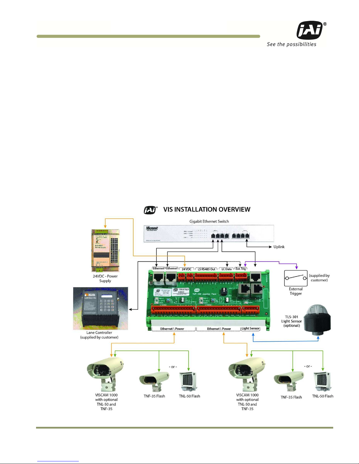
1.2 Product Overview and System Hardware Components
Figure 1. VISCAM 1000 Installation Overview
Page 8

VISCAM 1000 Systems
2
Introduction
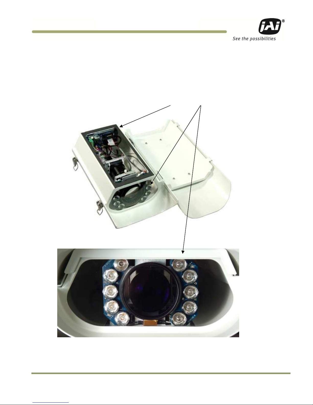
1.2.1 VISCAM 1000 System
The VISCAM 1000 uses a state-of-the-art camera system that freezes the motion of a rapidly moving vehicle
at high resolution, a zoom-lens or fixed focal length lens, and an on-axis illuminator, a weatherproof
housing with sun shield, heater resistors, I/O board, and a pan-tilt-roll mounting bracket. See Figure 2.
The VISCAM 1000 (All-In-One) features an optional embedded JAI trigger/light sensor for image triggering
and image contrast control. It also features an optional embedded LED-1000 illuminator (infrared, white or
blue) for independent 24/7 operation and excellent license plate contrast.
1.2.2 External Traffic Light Sensor – TLS-301 (optional)
The JAI Traffic Light Sensor TLS-301 provides an option to using VISCAM 1000’s built-in light sensing
capabilities described in Section 4.10.3. The TLS-301 estimates vehicles’ license plate lighting conditions
and controls the exposure and gain parameters of each camera to ensure high contrast images of vehicles
traveling through the field of view and their license plates, regardless of vehicle speed, weather or
ambient light conditions. For more information about the TLS-301, see Appendix B at the end of this
document.
1.2.3 External Light Sources
JAI offers a full lineup of lighting solutions optimized for a large number of applications.
The TNF-35 Traffic Night Flash unit is a 17W, long-life flash with an effective life span of up to 4 million
flashes. It comes in various application specific configurations for emission spectrum. With the standard
filter it generates light in wavelengths that are invisible to the human eye, but visible to the camera. For
more information about the TNF-35, see Appendix C at the end of this document.
The TNL-50 is a newer, high-performance LED Flash intended for traffic applications, including automated
number plate reading systems. The TNL-50 is field proven to produce high-contrast images of passing
vehicles and their number plates. With its very high light output, versatility, ease of installation and its
compact size, it makes it easy to see why it is an industry leading illumination solution. It also comes in
three configurations, broadband white, NIR, and blue to support various applications. Additional
information about installing and configuring the TNL-50 can be found in Sections 3.3 and 4.7 of this
document.
Both the TNL-50 and TNF-35 are automatically enabled whenever the camera or the optional TLS-301 Light
Sensor determines that ambient light is insufficient to produce a picture of usable quality.
1.2.4 Embedded Light Sources (LED-1000 IR, white or blue)
Various applications require the use of an embedded illuminator. JAI offers the LED-1000 illuminator with
infrared, white, or blue LEDs. See Figure 2.
1.2.5 VJP-300 Junction Panel
The J-Panel is the central connection point for the VIS components. The J-Panel is a DIN-Rail mounted PCB
(printed circuit board) equipped with various interface terminals for interconnection. Each J-panel can
support up to two VISCAM systems.
1.2.6 Optional 24V DC Power Supply
JAI provides a robust industrial rated power supply.
1.2.7 Optional gigabit Ethernet switch
JAI recommends using a field-proven industrial rated gigabit Ethernet switch.
1.2.8 System interconnection cables
JAI supplies a cabling solution that has proven its reliability on a large number of installation sites.
Page 9
Introduction 3
VISCAM 1000 Systems
1.3 VISCAM 1000 Product Line
The VISCAM 1000 houses a JAI TS(C)-5000EN camera. The EN camera series are Ethernet based with a built
in processor using an embedded Linux O/S for various operations, such as handling communication with
lane controller and back office, frame storage, JPEG compression, and so on. An optional external TLS-301
Traffic Light Sensor is available, as well as optional embedded LED-1000 illuminator.
Figure 2. VIS-CAM 1000 System With EIO 302 I/O board and LED-1000
Page 10
VISCAM 1000 Systems
4
Installing the VIS
2 Preparing for installation
2.1 Installation Preparation
To prepare for installation, consider the fundamental requirements for an effective deployment of the
Vehicle Imaging Subsystem. There are two basic configurations: overhead (over the lane) or side fire
(beside the lane). Figure 3 depicts a typical overhead configuration. Figure 4 depicts a typical side fire
configuration.
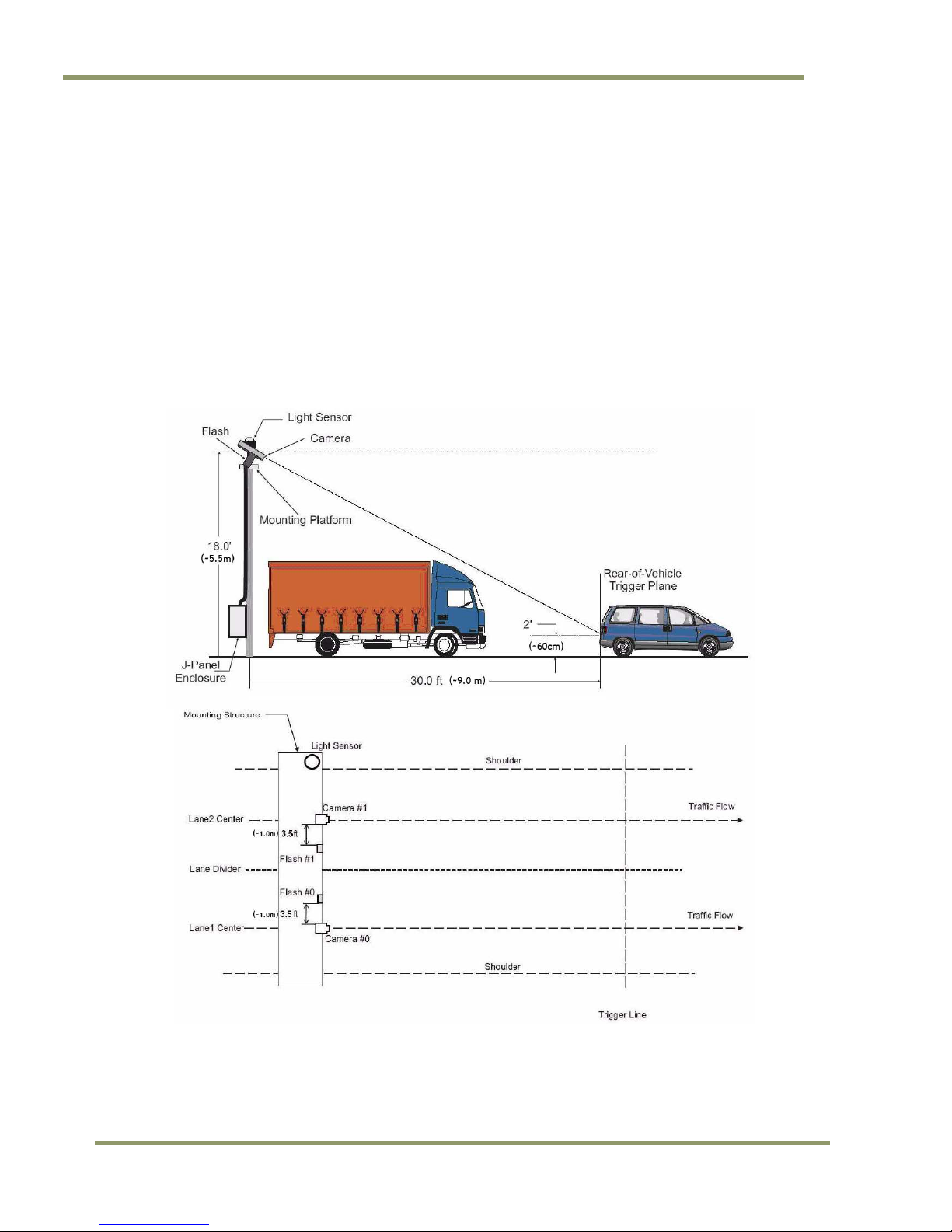
2.2 Overhead Positioning
Over lane camera mounting is always employed when the road width being monitored contains three or
more lanes of traffic, when a convenient overhead structure is already in place, or when preventing
vandalism is a paramount concern.
Figure 3. Typical Overhead Site Layout for a single lane
Page 11

Installing the VIS 5
VISCAM 1000 Systems
(a) Single Lane or Dual lane considerations
Figure 3 shows a typical single lane configuration. However, with the VISCAM 1000’s higher 5Mpixel
resolution, it can now cover up to two lanes of traffic.
The VISCAM 1000’s varifocal (zoom) lens is adjusted during installation to create the following conditions:
Standard for US style of plates: 135 pixels across a 1 foot wide license plate placed 2 feet above the ground
level at the nominal trigger position (ground loop, etc.). With typical US lane coverage (14’), the VISCAM
1000 will yield ~180 pixels/plate. If maintaining the 135 pixels per plate, the lane coverage is now 18’.
Standard for European style of plates: 140 pixels across a 50 cm wide license plate placed 60 cm above the
ground level at the nominal trigger position (ground loop, etc.). The coverage is now up to 9 meters, which
can definitely cover two lanes.
(Note: this can differ for other regions or plate styles.) See Section 4 for set up instructions. This resolution
maximizes license plate reader, vehicle matcher, or other image processing techniques performance. The
highest performance from the subsystem is achieved when the variation in plate size is kept to within ±5%,
which typically means that the vehicle trigger accuracy should be within ±1 foot/30 cm (@ trigger plane
defined by client.) at all speeds. Low latency vehicle triggering is very important and should not be
overlooked. Please contact JAI for support on this issue if needed.
(b) Camera tilt considerations
The requirement to freeze the motion of high-speed vehicles limits how steep or shallow the tilt angle of
the camera may be. For example, it is important to prevent the horizon from appearing in the image, and
thereby allowing the sun to blind the camera. For over lane installations, a camera tilt between 20° to 30°
is recommended, with 25° being considered the optimal angle. This angle of tilt is the best compromise
between minimizing visibility blockages caused by closely spaced vehicles and maximizing plate visibility
for plate mounts that are slightly recessed or tilted downwards.
(b) Asynchronous triggering considerations
An embedded vehicle detector is employed to cause the camera to capture an image at the precise
moment the vehicle is in the best position to image both the vehicle and its license plate. If an external
triggering device is used (i.e. ground loop) the delay between the time the vehicle passes the trigger
position on the road and when the trigger signal actually reaches the VISCAM 1000 must be kept to a
minimum to prevent high-speed vehicles from moving out of the area viewed by the camera before the
image is snapped.
(c) Camera height versus trigger distance considerations
It is critically important to select the correct distance between the camera and the location on the road
where the camera is triggered to capture an image. Minimizing the cost of installation is usually also an
important concern. This means that whenever possible, it is best to use existing structures or previously
installed elements. Contact JAI for support on setting/validating site geometry.
Page 12

6
Installing the VIS
2.3 Side of Road Installation
Figure 4. Typical side fire road installation for a single lane
Table 1 below shows the typical distance from VISCAM 1000 to flash/light unit (distance normal from
camera-license plate axis):
Table 1 Typical spacing distance between VISCAM 1000 and flash/light unit
VISCAM
1000
Approx. Distance
in Feet
3.5
Approx. Distance
in Meters
1.0
If the flash is positioned closer to the camera, reflections from retro-reflective license plates will likely
cause overexposure. If it is positioned farther the license plates will be relatively less bright and the image
quality might be deteriorated since more gain will have to be applied by the camera in order to make the
license plates bright enough for ALPR. A solution to this would be to increase the light intensity of the flash
unit.
If the distance from the camera to the trigger line is further than 50 ft then the spacing between flash and
camera will have to be increased to avoid increasing the retro-reflectivity effect, and the flash light
intensity will have to be increased or else the background will not be visible in the image even when retroreflective license plates are close to saturation.
Page 13
Installing the VIS 7
VISCAM 1000 Systems
3 Installing the VIS - Vehicle Imaging System
The individual components of the system are electrically linked together as shown in Figure 1, “VISCAM
1000 Installation Overview”.
3.1 VIS Power Requirements
The maximum power to a VJP-300 J-Panel is:
SYSTEM COMPONENTS
CURRENT
(STEADY STATE)
CURRENT
(INRUSH)
VISCAM 1000 System #0 (with heater on) 2.0A 3.5A
VISCAM 1000 System #1 (with heater on) 2.0A 3.5A
VJP-300 J-Panel 0.2A 1.5A
Total 4.2A 6.5A*
* Since all devices are connected to VJP-300 J-Panel, it limits total inrush current to 6.5A.
3.1.1 Installing the VISCAM 1000 System
The VISCAM 1000 has connections to the J-Panel and an optional Flash Night Light. In general, the
camera(s) should be aimed at the most likely cross-lane position of the vehicle license plates. See
“Installation Preparation” in Section 2 for general site layout guidelines. To install the camera(s):
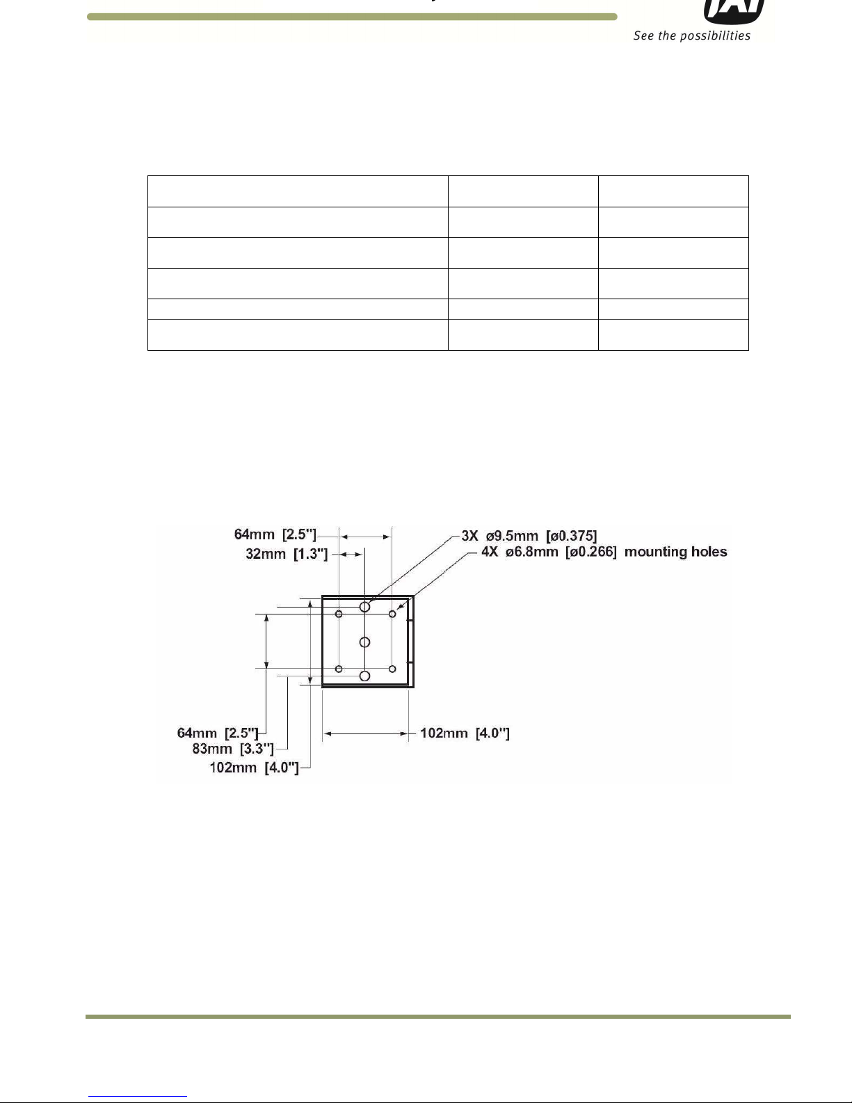
1. Attach VISCAM 1000, with mount, to the mounting structure. The hole pattern is shown in Figure 5 below:
Figure 5. VISCAM 1000 Mount Dimensions.
Page 14

8
Installing the VIS
2. Route the VISCAM 1000 end of the camera cable in accordance with local electrical code requirements.
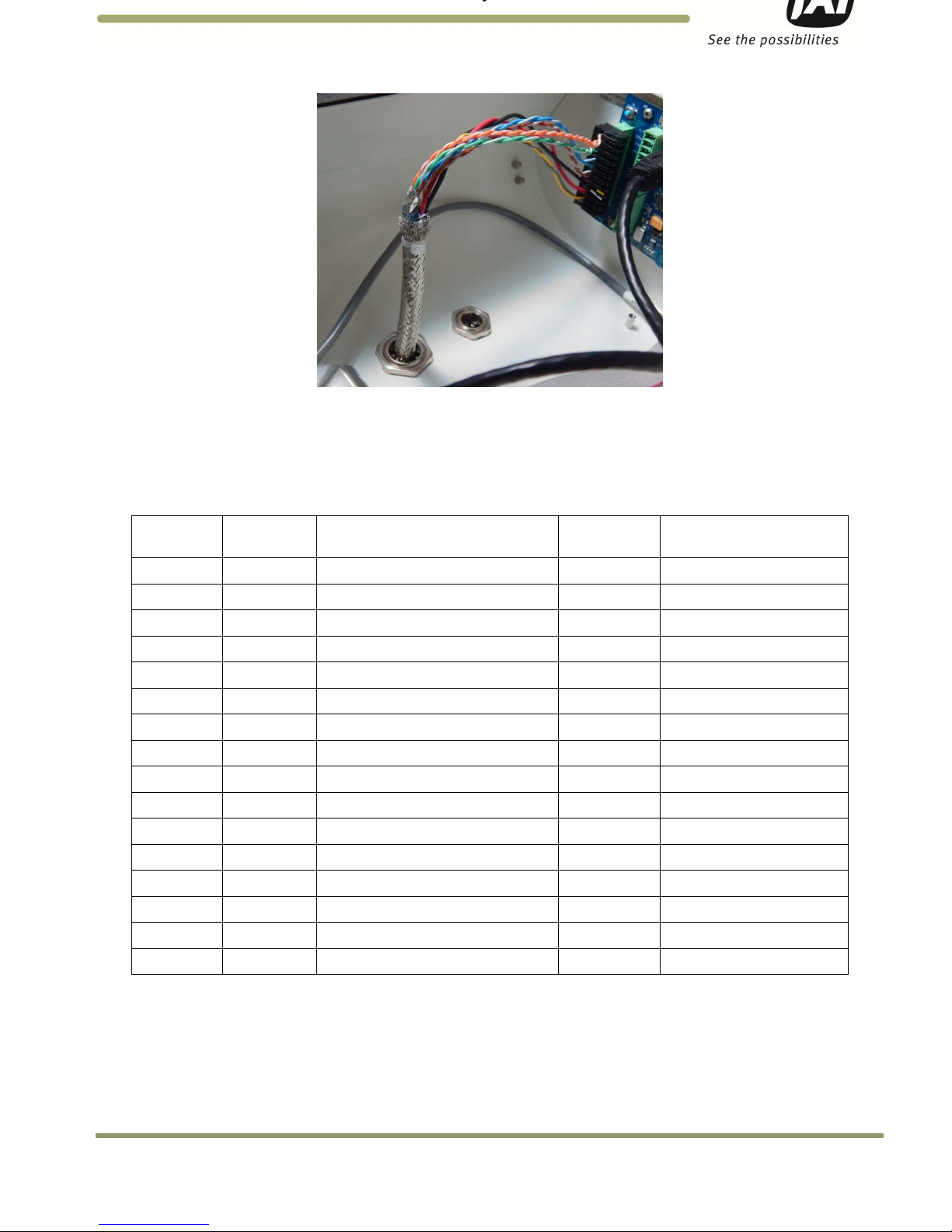
3. The jacket is removed from the cable on the camera end a distance of 7” (~18cm) (1). A thin wire is attached
around the end of the cable to keep the braid in place (1). The cord grip sealing nut is mounted on the cable
(3). See Figure 6.
Figure 6. VISCAM 1000 cabling as it appears after jacket is removed
4. Route cable through enclosure cord grip. Braid/foil shield should be aligned with the cord grip nut inside
enclosure to ensure proper shield connection with EMI cord grip. See Figure 7.
Figure 7. Cable is routed properly to ensure proper shield connection
5. Hand-tighten the sealing nut as far as possible. Hold the body hex stationary with a wrench (24mm). Using a
second wrench (24mm), tighten the sealing nut until the cable is securely held in place. Torque to
approximately 35 in. lbs. (3.9 Nm)
6. Move the thin wire 5 cm away from the cable end and fold the braid back over the thin wire. Use a cable strip
to keep the braid in place. Remove foils and fillers from the cable end. Separate and strip the wires. The 2
pairs of multicore wire can be fitted with bootlace ferrules to keep the cores in place. Connect wires to
terminal block X4 on the VISCAM 1000 I/O Board in accordance with wiring diagram on enclosures inner lid (see
Appendix A). Plug terminal block back to X4 position on VISCAM 1000 I/O Board. Close and secure enclosure lid
with 2 latches. See Figures 8 and 9.
Figure 8. VISCAM 1000 Cabling.
Outer
Braid
Grou
n
ding
Tongues
Grounding
Tongues
Braid is
folded back
Page 15
Installing the VIS 9
VISCAM 1000 Systems
Figure 9. Wires are inserted in VISCAM 1000 I/O board X4 connector
3.2 Installing the VJP-300 Junction Panel
3.2.1 Connection to VISCAM 1000 (X1 AND X2)
The VISCAM 1000 connections to the J-Panel (junction panel) are shown in Table 2 and Figure 10.
Table 2 VISCAM 1000 connections to the J-Panel.
VJP-300
X1, X2 Pin #
VISCAM AIO
X4 Pin #
Wire Color Signal Remarks
1 1 White/orange in Cat5e cable
Ethernet A+
2 2 Orange in Cat5e cable
Ethernet A
-
3 3 White/green in Cat5e cable
Ethernet B+
4 4 Green in Cat5e cable
Ethernet B
-
5 5 White/blue in Cat5e cable
Ethernet C+
6 6 Blue in Cat5e cable
Ethernet C
-
7 7 White/brown in Cat5e cable
Ethernet D+
8 8 Brown in Cat5e cable
Ethernet D
-
9 9 Black wire
Gnd 18 AWG
10 10 Red wire
+24V dc
18 AWG
11 11 Yellow
Vinit+
Trigger
signal, 24 AWG
12 12 Grey Vinit-
Trigger signal, 24 AWG
13 nc
14 nc
15 nc
16 nc
Page 16
10
Installing the VIS
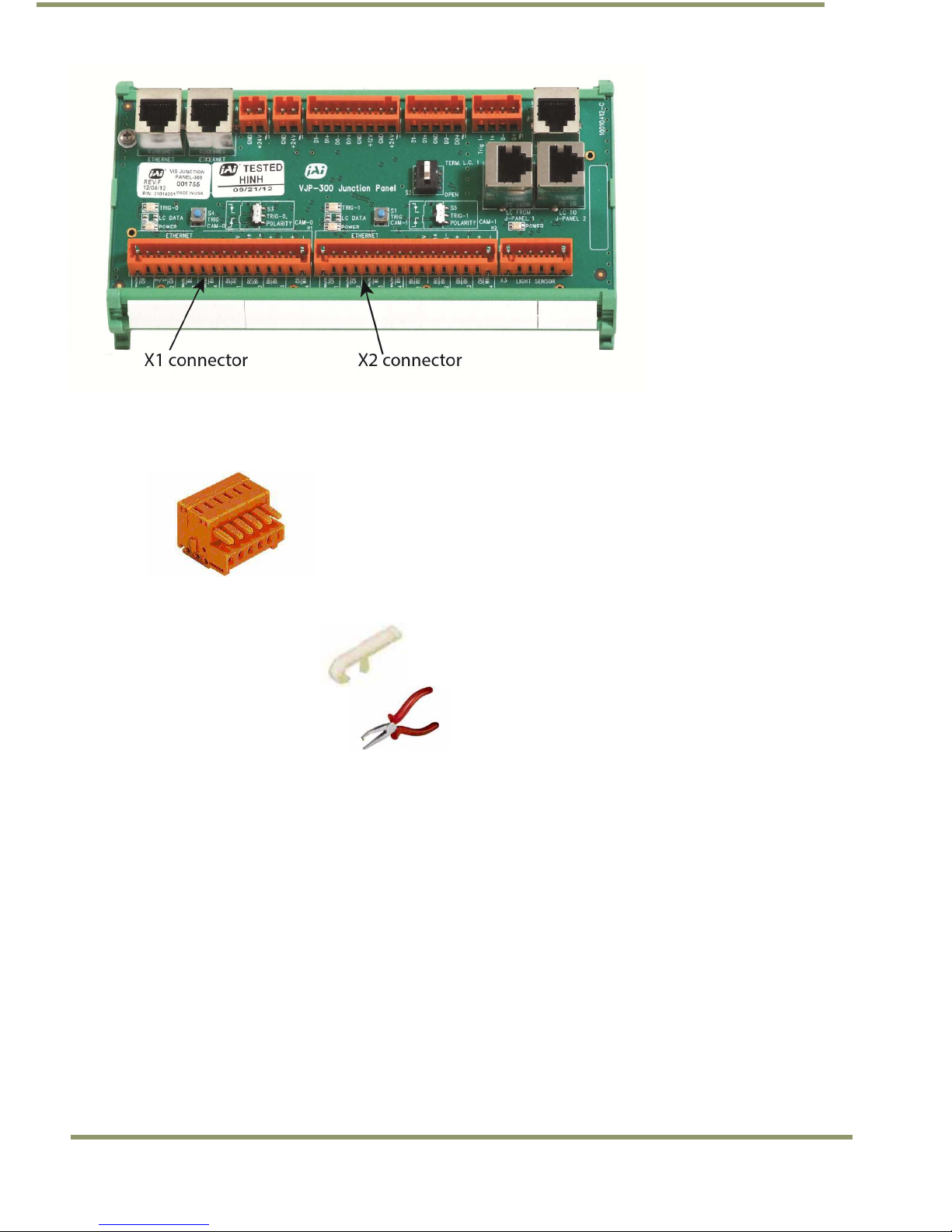
Figure 10. VJP-300 J-Panel X1 and X2 connectors
The connectors on the VJP-300 J-Panel are pluggable terminal blocks with pin spacing of 3.81 mm/ 0.15
inch from WAGO. The contacts are spring loaded. See Figure 11.
Figure 11. Terminal block
When mounting the wire into the connector the wire is stripped 7mm. The connector spring is released by
using one of two tools:
WAGO 734-230
JAI part number 10010134
WAGO 210-250
JAI part number 10014057
The wire is inserted and the spring is activated.
Page 17
Installing the VIS 11
VISCAM 1000 Systems
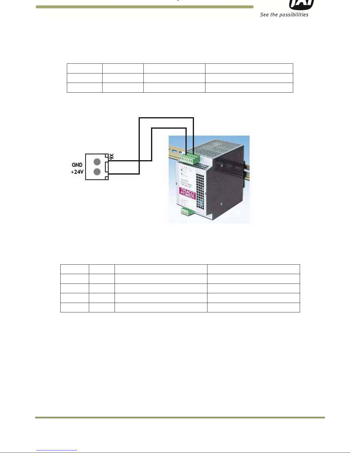
3.2.2 X6 Power Input Connector
The Power Input connection to the J-Panel is shown in Table 3 and Figure 12. Note: X7 is in parallel to X6.
Table 3 Power input to the J-Panel
X6 Pin #
Signal
Description
Connection to
1 +24V +24V dc
24V DC power supply + output
2 GND +24V return
24V DC power supply return
Figure 12. X-6 Power input connection
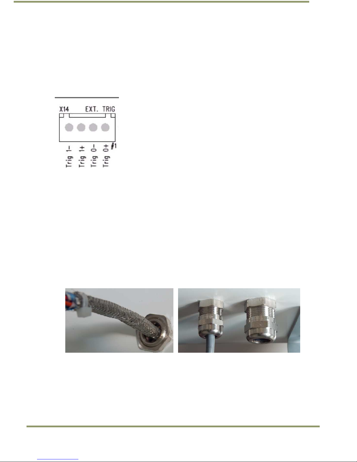
3.2.3 Trigger Input Connector (X14)
The Trigger input connection to the J-Panel is connector X14. The connections are listed in Table 4 and
Figure 13.
Table 4 Trigger input connector.
X14 Pin #
Signal
Description
Connection to
1 Trig0+
Positive Trigger input to
camera 0
Trigger device positive terminal
2 Trig0
- Negative Trigger input to camera 0
Trigger device negative terminal
3 Trig1+
Positive Trigger input to camera 1
Trigger device positive terminal
4 Trig1
- Negative Trigger input to camera 1
Trigger
device negative terminal
3.2.5 (a) Trigger polarity
The switches S3 and S5 set the trigger polarity:
If the trigger signal is normally low (no voltage at trigger input) the switch shall be in position:
Arrow up - positive going
If the trigger signal is normally high (voltage at trigger input) the switch shall be in position:
Arrow down – negative going
As a guideline the two LEDs marked TRIG-0 and TRIG-1 on the VJP-300 J-Panel shall be off when no trigger
pulse is present.
Page 18
12
Installing the VIS
3.2.5 (b) Test Trigger
Activating switches (push buttons) S1 and S4 generates a trigger pulse for test purposes. Only one trigger
pulse is generated each time the switch is activated (only works in arrow up position).
The duration of the trigger pulse is approximately 4 ms.
The trigger indicator LEDs flash when the test trigger switch is activated.
Figure 13. X14 Wiring
3.3 Installing the TNL-50
Securely install night light/flash unit on mounting structure. Roughly aim flash at trigger line (precision
aiming will occur when the system is up and running). See night light datasheet for mounting hole pattern
dimensions.
1. Disconnect wires from interconnection cable’s end connector in order to run cable through VISCAM
1000 enclosure’s cordgrip.
2. Route cable through enclosure cord grip. Braid/foil shield should be aligned with the cord grip nut
inside enclosure to ensure proper shield connection with EMI cord grip. See Figure 14 (left).
3. Hand-tighten the cord grip sealing nut as far as possible. Hold the body hex stationary with a wrench.
Using a second wrench, tighten the sealing nut until the cable is securely held in place. Torque to
approximately 35 in-lbs. (3.9 Nm). See Figure 14 (right).
Figure 14. Insert cable in enclosure and secure cordgrip
4. Connect wires to terminal blocks X5 & X12 on the VISCAM 1000 I/O Board in accordance with wiring diagram
on enclosure’s inner lid (see appendix A). Make sure settings are set per I/O Board Settings Diagram:
a. For TNL-50 Refer to Figure 15 and Table 5.
Page 19

Installing the VIS 13
VISCAM 1000 Systems
Figure 15. Connect TNL-50 wires to terminal blocks X5 and X12 on I/O Board
Table 5 TNL-50 flash unit connection in VISCAM AIO.
Pin X5
Signal
Wire Color
Description
Connection to
1 I/O Gnd
Black
I/O Board
Gnd Pin 2 (see Figure
15)
2 Gnd Black Flash Gnd
Flash ground (negative power terminal)
(GROUND)
3 Out White
Strobe out
Strobe input on flash unit (STROBE OUT)
4 Stat Blue Strobe status
Status output from flash unit (STROBE
STATUS)
5 FPWR Red Flash power
Power from
I/O Board
to output circuit on
I/O Board (pin 6)
6 24V Red
IO board 24V (Fused
0.5A)
Pin 5 (see Figure 15)
Pin X12
Signal
Wire Color
Description
Connection to
7 RS-485+ Green
RS-
485+ For controlling TNL
-
50 Parameters
8 RS-485-
Orange
RS-
485-
For controlling TNL
-
50 Parameters
Page 20

VISCAM 1000 Systems
14
System Set-Up
4 System Set-Up
This section provides a generic procedure for aligning one or more VISCAM 1000 system and associated
equipment at a site.
The example installation process described in this section assumes that:
• The cameras are being mounted on an overhead structure directly over the lane(s) being observed. The process
for aligning a camera mounted at the side of a lane is essentially the same as aligning a single camera mounted
directly overhead.
• The unit employs vehicle detection that will automatically trigger the camera. To determine where the vehicle
will trigger, the ENSetup program displays a trigger area region. This region shows the area where the camera
will detect a moving vehicle. This will give the approximate trigger line. Since the unit is using motion
detection technology, the trigger line will vary a little depending on the speed of the vehicle.
• If the installation utilizes other modes for triggering, the unit can also accept a discrete TTL or Ethernet signal
to the VISCAM 1000 system whenever the back (or front) of a vehicle crosses a fixed line across the road. This
line is referred to as the “trigger line” in this document.
• The installer should be familiar with using the ENSetup program supplied by JAI. Make sure you are using the
latest version by checking at www.jai.com. Please refer to the ENSetup Program User’s Guide if you are
unfamiliar with this software. JAI offers engineering support and software tools to help select the optimum
camera and trigger locations to meet your specific project needs.
• System settings are set to factory default value. This can be done by pressing the Load Factory Defaults button
on the tool bar in the Properties window.
4.1 Pre-Alignment Checklist
• Validate targeted lane coverage and lane overlap (if any)
• Make sure you have an appropriate laptop computer with the JAI ENSetup program installed.
• The setup computer needs to have an Ethernet network adapter installed (preferably 1 Gigabit Ethernet
Adapter) and the TCP/IP network configured with the correct IP-address, subnet-mask and default-gateway.
• The setup computer and the cameras need to be on the same subnet. The cameras are shipped with the
standard IP-address “10.0.0.65” and subnet-address “255.255.255.0”, and the setup computer needs to be
assigned an IP-address “10.0.0.xx” in order to automatically discover the cameras using the ENSetup program
(NB! “xx” must not be “65”).
• All cameras have to be given unique IP-addresses before the alignment begins. This is done using the ENSetup
application.
• Confirm all VIS components and cables are properly connected.
• Ensure network meets minimal system requirements (see Appendix D)
4.2 Select a Suitable Vehicle, License Plate, and Plate Stand for the Setup
To accurately set up the Vehicle Imaging Subsystem, the system installers need access to:
1. A vehicle that can be temporarily parked on the road
2. A plate that is:
a. typical in size and color for the site
b. clean, flat and in “like new” condition
Page 21

System Set-Up 15
VISCAM 1000 Systems
4.3 Connect the Setup Computer to the Camera
• Position the setup computer next to the camera being aligned. Make sure that no portion of the computer or
cables interfere with the camera’s view of the road.
• Connect the setup computer’s network adapter to the camera network. If the installation does not involve a
TLS-301 external light sensor, a direct connection between the setup computer and the camera can be used.
For installations that include a TLS-301, it is preferable to use a local Ethernet switch instead of a local direct
connection to the I/O board. (A direct connection between the setup computer and the camera will disconnect
the camera from the site LAN and thereby disconnect the light sensor as well.) See Figure 16 and follow the
instructions below if you are using a local Ethernet switch.
Disconnect camera’s Ethernet patch cord from the VISCAM 1000 I/O board and connect it to the
switch.
Then connect a new Ethernet patch cord from switch to VISCAM 1000 I/O board’s Ethernet port.
The Setup computer is then also connected to one of the free ports on the switch.
Note: If the switch is running on 24V dc, the I/O board is capable of supplying up to 0.5A on
connector X15 located next to X1 and X3. The pin marked with #1 on X15 is +24V dc.
Figure 16. Example of a network connection using a local switch
4.4 Drive and Park the Setup Vehicle Correctly
• Park the vehicle on the trigger line. Make sure that the vehicle is parked aimed in the same direction as the
average driver would point their car if they were driving through this section of roadway.
Page 22

VISCAM 1000 Systems
16
System Set-Up
4.5 Perform Initial Lens Adjustment and Camera Aiming
1. Back away all of the thumbscrews on the lens holder until they do not touch the knurled adjustment rings on
the lens.
2. Loosen the roll, pan, and tilt bolts on the JAI camera mounting head until each axis can be easily adjusted by
hand but any particular setting will stay in place after you let go.
3. Power on the setup computer and then start the ENSetup program. Press the “Video Window” button to open
the Video Window and then select the camera for adjustment from the tree-view on the left side of the
window. Press the “Live” button in the toolbar to start the video streaming. Press the “Tilt Line” button to
show the alignment guidelines.
The “Tilt Line” can be moved using the mouse, or if the “Tilt Line” is selected, using the arrow-keys. Keep in mind
the image in the video window by default is the center of the camera field of view. You may have to scroll the
image up or down to place the Tilt Line tool where you want the vehicle plate to be in the image.
4. Open EN Setup Video Window Settings. Configure Plate Width to the targeted number of pixels per plate. A
typical value is 135 – 150 pixels which provides high ALPR performance.
5. Interactively adjust the roll, pan, and tilt of the camera mount and the lens zoom and focus rings:
5.1 Adjust the lens focus ring (and camera pan and tilt as necessary) to obtain a focused image of the plate.
5.2 Adjust the lens zoom ring to obtain a plate width approximately equal to the distance between the short
vertical sizing marks that appear above the tilt line. Scroll the image horizontally to check edge to edge
coverage of the field of view as desired.
6. Repeat step 5 iteratively until no further adjustments are needed between each steps.
Note: For viewing full image right click in Video Window and select Preview Image. The adjustments still have
to be done from Video Window but the Preview shows how the full image looks.
Page 23

System Set-Up 17
VISCAM 1000 Systems
Figure 17. Initial Camera Alignment Display example
7. Turn on the “Roll Bar” display on the Setup computer and then roll the camera mount until the
horizontal bumper and trunk seams on the vehicle appear perfectly level with the horizontal line of the
display. Secure mount roll bolts. See Figure 18 for an example.
Figure 18. Roll Bar Display example
Page 24

VISCAM 1000 Systems
18
System Set-Up
Pan the camera mount until the plate is centered under the default position of the vertical line in the middle
of the “Roll Bar” display. The vertical line in the Roll Bar is in the center of the camera field of view. You can
use this feature to ensure the camera is properly aimed at the center of the lane. Securely tighten the pan
adjustment bolt.
Switch back to the “Tilt Line” display. Tilt the camera mount until the plate is positioned just above the tilt
line. Re-adjust the zoom and focus as necessary until the plate just fits in between the vertical markers on the
“Tilt Line”. Changing zoom usually requires that the tilt adjustment be modified also. Do not tighten the Tilt
bolts until after the final lens adjustment. See Figure 19.
Figure 19. Readjustment of camera tilt and zoom display
The camera mount and lens are now ready for final adjustment.
Page 25

System Set-Up 19
VISCAM 1000 Systems
4.6 Perform Final Camera Mount and Lens Adjustments
The final focus adjustment is facilitated using the “Focus Bar” display on the Video Window. Press the “Focus
Bar” button on the toolbar. This displays a “Focus Bar” marker on the Video Window that will open a separate
“Focus Bar” window where the pixel-values taken from the focus bar marker are displayed. The “Focus Bar”
marker can be moved with the mouse pointer, or if the “Focus Bar” marker is selected, using the arrow-keys.
1. Position the “Focus Bar” marker directly over the license plate. See Figure 20.
Figure 20. Focus Bar marker display
2. Adjust the lens zoom ring until the plate width just barely fits in between the short vertical markers on the tilt
line in the display.
3. Carefully adjust the lens focus ring until the focus bar waveform display is maximized in amplitude spread. The
“Focus percentage” display shown on the left side of the “Focus Bar Waveform” window should then be
maximized when the picture has got the best focus. If necessary, readjust the zoom and focus until the width
of the plate is just inside the vertical markers and the waveform spread of the bars is maximized. See Figure
21.
Page 26

VISCAM 1000 Systems
20
System Set-Up
Figure 21. Focus Bar Waveform display
4. Gently snug the zoom and focus lens holder thumbscrews against the lens without changing any of the lens
settings.
5. Use the mouse to move the red waveform cursors to the top and bottom of the waveform amplitude variation.
The “Black Cursor” is located at the bottom of the waveform display, and the “White Cursor” is located on the
top of the waveform display. See Figure 22.
6. Verify that the waveform amplitude variation (for characters in both direct light and shadow, if possible) is at
least 25 and that no portion of the waveform fully saturates either black or white.
Page 27

System Set-Up 21
VISCAM 1000 Systems
Figure 22. Focus Bar Waveform Display with waveform cursors
7. Use one hand to carefully hold the focus ring of the lens in place while you rotate the polarizer filter ring on
the very front of the lens with your other hand. Turn the filter ring until the white mark on the ring is oriented
straight up (or down). Secure the filter ring in place using the thumbscrew or with a small dab of RTV glue.
8. Print out the image of the screen using the “File -> Print…” menus on both the “Video Window” and the “Focus
Bar Waveform” windows to document the settings. If no printers are connected, the “PDFCreator” printer
driver can be used to save the windows as .pdf files.
9. Park the vehicle at the location where it is in a “crossover” position (i.e. between lanes) to check horizontal
coverage between adjacent cameras. Make adjustments as necessary to ensure adjacent cameras both have the
full plate in their respective fields of view.
10. If “Live” mode was used in EN Setup Video window make sure you click on “Freeze” before going to another
camera. “Live” mode stops images from being sent out over TCP and FTP.
4.7 TNL-50 Flash Alignment and settings
The following section provides a general procedure to align the TNL-50 flash head. Be sure to follow any
specific alignment procedure provided with your system.
Align the flash head at night and after aligning the cameras. Park a light colored vehicle at the trigger line
before proceeding with the alignment and flash intensity adjustments.
• Press the “Repetitive Trigger” button on the ENSetup toolbar. This will trigger the camera every second. Make
sure that the “Ethernet” trigger is enabled in the “Camera Properties” section “2 – Trigger”, property “External
Trigger Source”.
• Adjust the flash head tilt and pan control until the entire back of the vehicle is well and evenly illuminated. If
necessary, adjust the flash-head pan control to center the flash beam over the vehicle.
Page 28

VISCAM 1000 Systems
22
System Set-Up
• If the license plates are over-exposed by the TNL-50 Flash then there are multiple possible solutions to correct
this problem. Some of these solutions involve changing some of the VISCAM 1000 system parameters to reduce
sensitivity to nighttime illumination. Other solutions involve changing the brightness of the TNL-50 Flash by
adjusting some of the internal Flash unit settings. Please see next chapter for a detailed description of the
possible solutions.
• Repeat pressing the “Repetitive Trigger” button on the ENSetup toolbar to stop flash firing. Repeat the above
steps for each camera/flash.
4.7.1 TNL-50 Flash Settings
TNL-50 Flash unit come in three different versions: a white light, blue light and NIR light version. All of these
versions primarily work as flash (strobe) unit that illuminate vehicles and license plates when the cameras are
being triggered during low-light conditions.
Both the white and the blue light versions are visible to the human eye so they have an additional “Traffic
Safety Mode” feature built-in which provides a constant light output from the flash units between the bright
strobe flashes. This will make the bright strobe flashes seem less disturbing to the passing vehicles.
The strobe brightness and the Traffic Safety Mode brightness settings are adjusted individually depending on
the customer requirements.
It is possible to adjust the TNL-50 Flash settings directly from ENSetup.
The TNL-50 Continuous Light and Flash Light intensities are set up directly from the EN Setup Properties
window (Category “4 – Light”) by adjusting the “Flash Intensity”, “Flash Traffic Safety Night Intensity” and
“Flash Traffic Safety Day Intensity” settings seen below.
Figure 23. TNL-50 Flash Intensity settings in ENSetup
The light intensities are all specified in percent of maximum intensity output.
Furthermore a dedicated “TNL-50 Light Settings” dialog can be opened using the context menu for the selected
TS(C)-5000EN camera by selecting the “->Advanced Settings->Configure TNL-50 Light Settings”.
Note: as of firmware version later than Jan 2015 the Flash Intensity and Traffic Safety Intensity settings will
override TNL-50 settings. If you send commands directly to the TNL-50 to change intensity the camera will
change it back when it needs to adjust lighting.
Page 29

System Set-Up 23
VISCAM 1000 Systems
Note: Older version of EN Setup has incorrect Alarm Status options for TNL-50. The correct setting should be
“Normally High, Low -> Alarm …” Also the Flash Status Type setting of IO Board needs to be set to TNF DC;
please see Appendix A.
Figure 24. TNL-50 Flash settings context menu in ENSetup
This opens the settings dialog shown below:
Figure 25. TNL-50 Flash settings dialog
Page 30

VISCAM 1000 Systems
24
System Set-Up
Continuous Light Intensity (Traffic Safety Mode): Continuous light setting is only applicable for the white and
blue light versions of the TNL-50. The purpose of this light is to make the flash pulse less disturbing for
oncoming traffic. It has no influence on the image illumination.
Flash Intensity: These settings control the brightness of the TNL-50 when the camera is triggered. This is
typically only used during night when the ambient light level gets below a certain threshold. It makes it
possible to identify the vehicles at night as well as make the license plates readable.
The TNL-50 Flash intensity is very high compared to older flash units so the license plates can easily be
overexposed at night if the Flash Intensity is set too high. Both the distance between the TNL-50 and the
optical axis of the camera - as well as the overall distance from the flash unit to the vehicle will strongly
influence the brightness of the license plate at night. If the license plate gets completely washed out
(completely saturated so the letters and numbers become unreadable) then there are two basic options to
solve this via the flash unit itself: either lower the intensity of the TNL-50 or to move the TNL-50 further away
from the camera (this however only applies if the license plates are retro-reflective!)
Another option is to change the exposure settings inside the camera and thereby lower the cameras gain so the
license plates are less bright in the image. This will also improve the overall image quality since the noise level
in the images will be reduced when the gain is lowered. But typically this also makes the overall brightness of
the images darker so the vehicles become less visible in the images at night.
4.8 LED-1000 Embedded Illuminator Setup
The LED-1000 Embedded Illuminator is primarily used by the VISCAM 1000 to provide sufficient light for the
built-in Vehicle Detector trigger system, so the camera will be able to trigger during night time when the
ambient light is insufficient to light up the vehicles. The LED-1000 is also utilized during the daytime to make
the retro-reflective license plates stand out when they are in shadow condition. The brighter license plates
will enhance the contrast and the readability leading to higher ALPR performance.
The LED-1000 illuminator has two usage models similar to the TNL-50 flash unit: Traffic Safety (Continuous
Light) and Triggered Flash Mode.
Traffic Safety (Continuous Light):
The flash is constantly on at a specified brightness configurable in the LED-300/1000 Light Settings window.
Right click on the camera symbol and select Advanced Settings –> Configure LED-1000 Light Settings.
A dialog box will open and the settings for the LED-1000 light can be controlled from here:
Figure 26. LED-1000 Light Settings dialog box
When selecting light intensity settings, those settings are automatically saved in the I/O Board and become the
default settings next time the system is powered on. When selecting a “custom” setting, the SET button must
be selected for the value to take effect.
Page 31

System Set-Up 25
VISCAM 1000 Systems
Triggered Flash:
When the camera captures an image, the Internal Flash can flash at a different light level. The Internal Flash
Mode and Internal Flash Intensity settings affect this usage.
Internal Flash Mode:
There are three options available as of EN APP firmware version January 2015 (see Figure 27):
Figure 27. LED-1000 Mode selections in ENSetup
- Off: the internal LED light (LED-1000) is always off
- On Always: internal LED light is always flashed when triggered. The light is needed for Vehicle Detector to
work properly therefore this is the recommended setting.
- Auto Light Level: light level can be controlled automatically with the help of ALC or ADR. The “Internal Flash
Auto Intensity …” settings let you fine tune the light level (see Figure 28).
Figure 28. LED-1000 Flash Mode and Intensity settings in ENSetup
When Auto Light Level is selected the following settings take effect:
Page 32

VISCAM 1000 Systems
26
System Set-Up
- Internal Flash Auto Intensity Minimum: the lowest light level the ALC/ADR will set the Internal Flash
Intensity.
- Internal Flash Auto Intensity Maximum: the highest light level the ALC/ADR will set the Internal Flash
Intensity.
- Internal Flash Auto Intensity Knee Point 1 and Knee Point 2: have units in Light Sensor (LS A-Side from ALC
or ADR). Intensity is equal to
o If LS value < Knee Point 1 then intensity equals Intensity Minimum
o If LS value > Knee Point 2 then intensity equals Intensity Maximum
o Otherwise intensity equals
()(
)
+
4.9 Trigger Mode Selection
The VISCAM 1000 system offers several trigger sources. They can all work independently, but can all be
selected in parallel:
• TTL Trigger
• Serial Trigger (NOT USED – CANNOT BE SELECTED)
• Ethernet Trigger
• Vehicle Detector
The selection is in the Trigger control panel in the Properties window for the camera:
4.9.1 Trigger Synchronization Mode Selection
In addition to the selection of External Trigger Source, there is also the selection of Trigger Sync Mode where
the capture rate (frames per second) of the sensor can be controlled. The maximum allowed shutter time
varies, depending on the rate selected as shown in the list below:
1. Internal 50 fps – 3 ms maximum shutter length
2. Internal 60 fps – 3.5 ms maximum shutter length
3. Internal 72 fps (default selection) – 1 ms maximum shutter length
4. External 50 fps – 3 ms maximum shutter length
5. External 60 fps – 3.5 ms maximum shutter length
6. External 72 fps – 3 ms maximum shutter length
As seen in the above list, the camera’s continuous frame rate can either be set to 50, 60 or 72 frames per
second and the camera will actually be capturing images continuously in order for the built-in Vehicle
Detector, as well as the ALC (Automatic Level Control) to work – even if no vehicles are present and no triggers
are sent to the camera.
Page 33

System Set-Up 27
VISCAM 1000 Systems
This is different from the older generations of EN-cameras where the image sensors were using “asynchronous
triggers”. This meant that the imaging sensor was waiting for the next vehicle to pass before an image would
be taken!
The selection of External allows the camera to be externally synchronized with a 50, 60, or 72Hz Sync input.
This feature is necessary if one or more cameras needs to be synchronized to an external synchronization
source – for instance to the A/C power frequency in red-light systems, where the traffic light signals use LED’s
which are “pulsed” from the A/C power source. The 50 Hz and 60 Hz should in this case be selected based on
the A/C frequency where the cameras are installed.
4.10 Automatic Triggering and Light Sensing Configuration
This section describes the parameters to configure when setting up for automatic triggering (Vehicle Detector
Trigger) and light sensing (ALC).
4.10.1 Vehicle Detector Trigger Settings
Select “Vehicle Detector” within “External Trigger Source” to enable Vehicle Detector Trigger. The system will
automatically detect moving vehicles in up to two separate lanes. Note that the traffic in both lanes must be
moving in the same direction.
The Vehicle Detector uses a 200-line high detection area that covers the full width of the image. This detection
area is internally split into 9 horizontal detection grids. Each grid can be individually enabled or disabled. When
used in single lane mode, all 9 are used. When in dual lane mode, four grids are used per lane and the center
grid is normally disabled.
The Vehicle Detector properties are located in the Properties window of the camera in section 12: Vehicle
Detector
Figure 29. Vehicle Detector settings
Below is a short description of the Vehicle Detector parameters:
Shadow Suppression Mode – Disable/Enable shadow suppression. Enabling this feature helps reduce false
triggers caused by shadow. During certain times of day when the shadow is sufficiently dark compared to the
road surface, it could be mistaken as a vehicle by the VD. The shadow can be from a car in the adjacent lane,
or a long shadow cast in front of or behind the vehicle.
Sensitivity - This determines Trigger sensitivity of the system. The range is from .5000 to .9999 – or “Auto”. In
Auto mode the camera automatically adjusts the Vehicle Detector sensitivity based on the current exposure
settings.
The higher the value, the more sensitive the trigger will be. The selection of the setting should be determined
during the initial setup. Default setting is “Auto” and this is the recommended setting for the system, unless
the user application will actively control the sensitivity (no fixed sensitivity value will work correctly for all
light conditions – so active control will be necessary!)
Trigger Line - This determines the location of a “virtual trigger line” which in fact is the center line of a 200
lines high “Vehicle Detection Area” inside the image. It is specified as the line number of the center line
measured from the top of the image and down to the center line of the “Vehicle Detection Area”. The range is
from 350 to 1702 (default).
Page 34

VISCAM 1000 Systems
28
System Set-Up
Retrigger Delay - This setting determines the minimum number of frames between two consecutive triggers.
The actual time can be calculated as the number of frames multiplied by the frame-rate selected in the Trigger
Sync mode setting. If multiple triggers occur within this time then only the first trigger will be accepted. The
purpose for this setting is to minimize the number of “multi triggers” where the same vehicle generates
multiple triggers but only a single image is needed to identify the vehicle.
Lane Empty – This setting is essential to the “Rear Shot” Lane Direction mode (explained below). This specifies
the maximum number of “empty” frames the triggering system is allowed to wait in order to make sure that
the vehicle has left the detection area. If this value is too low then a lot of multi-triggers will be generated. If
it is too high then it limits the ability to detect tail-gating vehicles (in case the tail-gating vehicle is closer to
the vehicle in front than the number of frames specified). Default value is 11 and it is recommended to keep
this maximum value whenever possible.
Lane Configuration - This selection has the choice of Single Lane and Dual Lane. In Single Lane, the Vehicle
Detector algorithm uses the whole Vehicle Detection Area to detect a vehicle. In Dual lane, the image is
divided in half and each half is used to detect vehicles. Thus, if a vehicle happens to be crossing between
lanes, there may be an instance, where the same vehicle may be triggered in both lanes.
Lane Direction – This selects the way the Vehicle Detector triggers are generated. In “Rear Shot” mode the
vehicles will be travelling away from the camera and the triggers are generated when the vehicle leaves the
detection area. In “Front Shot” mode the vehicles will be travelling towards the camera and the triggers are
then generated when vehicles enter the detection area.
Detection Grid – It is possible to enable/disable the Vehicle Detection in each of the 9 grids of the detection
area. It is recommended to disable the middle (Grid 5) in dual-lane configuration. This will minimize the
number of multi-triggers that might occur if the passing vehicles get too close to the middle detection zone
(which is shared between both left and right lane).
4.10.2 Visualization helper for Vehicle Detector and ALC setup
The camera can superimpose the Vehicle Detection Area and ALC Area onto the image to help during trigger
line setup. To enable visualization enable them in “Debug Output Mask”:
1. On Image Graphics (Vehicle Detector): to show Vehicle Detection Area
2. On Image ALC Area: to show ALC Area.
Figure 30. VD and ALC visualization settings
*Be sure to disable the graphics when finished. They appear in the final image!
Figure 31. The visualization as displayed in image
Vehicle Detection Area (green boxes):
1. Each box represents 1 detection grid. There are 2 groups: left lane and right lane.
Page 35

System Set-Up 29
VISCAM 1000 Systems
2. Trigger Line: when in “Live” view mode, aim the camera so that the plates for each lane are at this Trigger
Line and in their respective side.
3. A trigger happens as a vehicle drives past the Trigger Line and comes out of the detection area.
3. The middle blue vertical line should be on top of and line up with the lane divider.
ALC Area (red & purple box):
The ALC area should be configured as close to the license plate area as possible to ensure accurate reading of
the current lighting conditions. Shadows cast onto the plate may not be cast on different parts of the field of
view making plate seems darker in the resulting image.
4.10.3 ADR settings in ALC mode
The VISCAM-1000 supports light sensing using an external (TLS-301) light sensor or using the internal ALC light
sensing functionality for exposure control of the camera. All light sensing settings are set up using ENSetup in
section 5 – ADR Control and the ones that are used by the ALC mode will be explained below.
Some of the settings are used in both external and internal light sensing mode - for example, ADR Shutter Max
specifies the longest (slowest) allowable shutter speed for auto exposure purposes, with values ranging from 0
(30 µs) to 855 (1000 µs).
Other settings are specific to the ALC mode of operation and these settings are marked in the figure below.
Figure 32. ADR Settings specific to ALC
1) Camera ADR Control – The ADR mode has to be set to ALC in order to enable the internal light sensing.
2) ALC Target Value – This is the “set-point” for the closed-loop control of the camera exposure. This value
represents the target average value for the ALC Region Of Interest (ROI). It is a 10-bit value which is then
four times higher than the average value measured in the output images from the VISCAM-1000 (which are
all in 8-bit resolution). So if the Target Value is set to 200 for instance, then the average intensity of the
ALC ROI in the output images will be around (200/4)=50. This value should be kept between 150 - 250 in
order to insure a proper brightness and contrast of the resulting images from the camera. By keeping the
value low there will be a larger “margin” so that over-exposed license plates can be avoided.
3) ALC Damping Factor – This setting controls the speed of the closed-loop control of the camera exposure. It
represents the percentage of change allowed by the control loop for each individual frame. A low value
(10-25) makes the ALC more stable and will give less fluctuation in the exposure. A high value (75-90) will
make the ALC very responsive but at the same time the brightness of the output images will vary a lot
depending on the brightness of the passing vehicles. It is recommended to keep the ALC Damping Factor as
low as 25% or even lower in order to prioritize stability over responsiveness of the ALC.
Page 36

VISCAM 1000 Systems
30
System Set-Up
4) ALC ADR Index Minimum/Maximum – These settings limit the exposure control range utilized by the ALC.
The minimum index will set the lowest ambient light level where the ADR will select the longest exposure
time and highest gain in the camera. By increasing this value the maximum gain will indirectly be limited
for the camera and hence result in images with less noise. This, however, also limits the total exposure of
the system and the resulting images will be darker in general. The maximum index sets the maximum
ambient light level where the ADR will select the shortest exposure time. When the maximum is set to
1500 then the minimum exposure time of the sensor will be used (approx. 30µs). It is recommended to
keep the maximum index at the default value (1500) and to set the minimum index to as low a value as
possible – but where the noise level is still acceptable and the license plates at night are not over-exposed!
A typical minimum index would be around 10-15 which yields a good balance between system sensitivity
and noise level.
5) ALC ROI top/bottom/left/right – these four settings specify the area from which the ALC calculates the
average measurements for the control loop. This area should be selected so it covers the background
(asphalt or concrete road tarmac) area where the vehicles will be located when the images are captured.
This will in most cases be close to the Vehicle Detection area. If the Vehicle Detector is in Rear Shot mode
then the ALC area should be put a bit higher than the detection area (since the vehicles are captured when
they are leaving the detection area). If the VD trigger line is being moved up or down then the ALC ROI
should be moved the same amount in the same direction.
4.11 High Dynamic Range Settings
The imaging sensor used in the VISCAM-1000 supports multi-slope integration. This makes it possible to increase
the dynamic range of the sensor, and helps avoid over-exposed license plates in challenging light scenarios
where the ALC control is unable to correctly assess the brightness of the license plate and the vehicles when
the images are captured. The challenging light scenarios are often caused by shadows being cast onto the scene
in a way where the ALC measures the average of the road surface in shadow – but where the vehicle will be in
the direct sun and thereby inadvertently cause the vehicle to become over-exposed!
The HDR settings are adjusted directly in ENSetup using section “10 – High Dynamic Range Control”.
Figure 33. HDR settings in ENSetup
1) HDR Enable: Selects if the multi-slope integration is enabled or disabled
2) HDR Slope 1/2 Reset percentage: Select the multi-slope reset time for the second and third slope of the
multi-slope integration of the sensor. The reset time is set as a percentage of the total exposure time so it
will automatically be adjusted when the exposure time is changed by the ADR. The higher the value – the
later the reset which in turn increase the dynamic range.
The multi-slope integration will change the sensors response to the light like shown in the example below:
Page 37

System Set-Up 31
VISCAM 1000 Systems
Figure 34. Example of different multi-slope integration settings
If the HDR functionality is switched off then the sensor will have a linear response to the light. If HDR is
enabled then the slope of the response curve will get a “knee-point”. When the light level gets above this level
then the sensor gets less sensitive to the light, (less steep curve) and will be able to image what would
otherwise result in an over saturated/clipped image.
Multi-slope integration will also result in a “compression” of response of the sensor above the knee-point, and
the “contrast” of the bright part of the image will be lower when the HDR level is increased. Another sideeffect is also that the images will get a “pinkish tint”, so that the color fidelity of the brighter areas of the
image will be lower.
The figure above shows two settings:
- Reset time at 70%/85% of the exposure time: This settings makes the sensor capable of coping with
approximately twice the amount of light compared to the linear response (HDR OFF)
- Reset time at 80%/90% of the exposure time: This settings makes the sensor capable of coping with
approximately four times the amount of light compared to the linear response (HDR OFF)
0 200 400 600 800 1000 1200 1400 1600 1800
0
50
100
150
200
250
300
Light level (fL)
Mean
OFF
ON, Level 6, Reset 70%/85%
ON, Level 6, Reset 80%/90%
0 200 400 600 800 1000 1200 1400 1600 1800
0
50
100
150
200
250
300
Light level (fL)
Mean
OFF
ON, Level 6, Reset 70%/85%
ON, Level 6, Reset 80%/90%
Page 38

VISCAM 1000 Systems
32
System Set-Up
It is recommended to use as little HDR as possible so that the compression and lower contrast in the images is
minimized.
4.12 Time Synchronization Settings
Most ITS systems require that all cameras are time synchronized – both with the back-office as well as with
each other. The VISCAM-1000 supports time synchronization using the standard Network Time Protocol (NTP)
where one or more designated NTP Servers provide the time for the whole system.
The NTP Time Synchronization is configured directly using ENSetup in section “14 – Time Synchronization”.
Figure 35. Time Synchronization settings in ENSetup
Before enabling the NTP Client all configuration parameters have to be set up, or else it will require a restart
of the NTP Client in order to make the parameters effective.
The following parameters need to be configured:
1) NTP Client Control – Enable or Disable the NTP client in the camera.
2) NTP-Server 1/2/3 IP-address: these parameters specify which NTP Server(s) on the network that the NTP-
Client will use for the time synchronization. The first IP-address in the list will be considered the preferred
server.
3) NTP Max estimated Error: Specifies the maximum estimated error allowed (in microseconds) before a
ERROR_NTP_TIME error telegram will be generated when an image is captured. This is typically used in
systems where there is a strict requirement to the synchronization accuracy of all cameras (like for
instance Section Control systems).
4) NTP Mode: This controls the NTP-Client mode of operation. Three modes are available: a) “Default”, b)
“Burst” and c) “Burst + Min/Max Poll intervals”. “Default” mode will use default configuration parameters
when the NTP Client daemon is started. “Burst” mode will speed up the initial communication to/from the
NTP Server and thereby help the NTP Client start/restart faster. “Burst + Min/Max Poll intervals” mode will
both speed up initial communication as well as set the minimum and maximum poll interval for
communication between the NTP Server and the NTP Client. This typically means that the minimum and
maximum poll intervals are changed to a lower value than that of the “Default” mode, thereby making the
NTP Client more responsive and more accurate – especially in cases where the NTP Server is not a high-end
dedicated time server, but instead is a service running on a standard PC on the network.
5) NTP Minimum/Maximum Poll interval: These two settings specify the poll interval range used by the NTP
Client. The values are defined in seconds as a power of two so a minimum value of 4 translates to 24
seconds = 16 seconds. A value of 6 translates into 26 seconds = 64 seconds. The minimum value is the poll
interval being used whenever the NTP Client starts up. It will then gradually increase the poll interval to
the maximum value and this maximum value will be used when the time synchronization is in a steady
state.
It is recommended to use the “Burst + Min/Max Poll Interval” mode when a standard PC is being utilized as the
NTP Server on the network.
Page 39

System Set-Up 33
VISCAM 1000 Systems
4.13 Solar Position Control for assisting the ALC
The ALC mode works well for in-image auto determination of gain and exposure time. There are situations
though in which the sun’s position makes it difficult to adjust the image properly.
Examples:
- The Sun is in front of the vehicle so that the plate is in the vehicle’s shadow but the road is bright. The
exposure and gain setting will make the plate dark.
- The Sun is directly behind the vehicle, and the plate’s retro-reflectivity will make it extremely bright.
The camera will be able to compensate for this if it can calculate the sun’s position. You can enable and
configure these controls in the Solar Position Control section.
For more details please see the Solar Position Control Application Note.
Solar Position Control: Enable or disable the Solar Position Control assistance for the ALC.
Camera Location Latitude and Longitude: The camera location is specified as a combination of the Latitude and
Longitude. The Latitude value is in “decimal degrees” where a positive value is degrees above equator (north)
and a negative value is degrees below equator (south). The Longitude is also specified in decimal degrees
where a positive number is degrees east of the “Prime Meridian - Greenwich” and a negative number is degrees
west of Greenwich. A good source for the location coordinates could be either from a GPS – or from reading the
location from various map sources.
1. Camera and vehicle directions:
a. Cameras Direction (Azimuth) is specified as the compass direction that the camera is facing,
where 0 degrees is “true north” and 180 degrees is when the camera is facing directly south.
b. Camera Tilt is the angle the camera is “tilted” down from the horizon. This angle is typically
between 25 degrees to 30 degrees.
c. Vehicle direction (or road direction) is the direction that vehicles will be travelling away from
the camera. This value is typically the same value as the camera azimuth (in gantry mounted
Page 40

VISCAM 1000 Systems
34
System Set-Up
camera systems where the cameras are mounted straight above the road). If on the other
hand the cameras are mounted on the side of the road then the vehicle direction and the
camera direction values will be different! It is however important to note that this angle is
always in the same “general direction” as the cameras – no matter if the vehicles are moving
towards the camera or away from the camera! The direction will always need to be specified
as the angle away from the camera.
2. Shadow Boost Factor settings:
The Shadow Boost Factor is the maximum multiplication factor applied to the ALC set-point value when the
back of the vehicle is in “self-shadow” and the license plates are in shadow as well. The Shadow Boost Factor
Angle specifies the range of sun azimuth angles where the Shadow Boost Factor will gradually be increasingly
applied. It starts out with no boost factor when the sun angle is perpendicular to the vehicle direction, then
gradually increases to the maximum boost factor within the Boost Factor Angle degrees.
3. Road Reflection Boost Factor settings:
The Road Reflection Boost Factor is the maximum multiplication factor applied to the ALC set-point value. This
happens when the sun is right in front of the camera and the sunlight bounces off the road surface. The Road
Reflection Boost Factor Angle specifies the range of sun azimuth and elevation angles where the Road
Reflection Boost Factor will gradually be increasingly applied. It starts out with no boost factor when the sun
angle is less than or equal to this angle from the camera direction and elevation - and is then gradually
increased to the maximum boost factor when the sun is straight in front of the camera and the sun elevation is
the same as the camera tilt angle.
It is important to note that the Shadow Boost Factor and the Road Reflection Boost Factor can be applied at
the same time! This means that when the Road Reflection Factor is at its maximum, then the Shadow Boost
Factor will also be at its maximum – hence applying the combined boost factor to the ALC set-point!
4. Direct Sun Reduction Factor settings:
The Direct Sun Reduction factor is the maximum reduction in the ALC set-point value when the sun is right
behind the camera. The Direct Sun Reduction Factor Angle specifies the range of sun azimuth and elevation
angles where the Direct Sun Reduction Factor will be increasingly applied. It starts out with no reduction factor
when the sun angle is less than or equal to this angle from the camera direction and elevation. It is then
gradually increased to the maximum reduction factor when the sun is straight behind the camera and the sun
elevation is the same as the camera tilt angle.
5. Min/Max Shadow Suppression Elevation settings:
The sun position can also be used for automatically enabling the “Shadow Suppression” in the VISCAM-1000
Vehicle Detector. The camera automatically calculates the sun elevation. If this value is within the Min and
Max Shadow Suppression Elevation then Shadow Suppression is turned on when the Vehicle Detector trigger is
enabled.
4.14 Video Streaming and Recording
In addition to capturing triggered “still” images of passing vehicles and plates, the VISCAM 1000 system offers
two types of video capture functions: live streaming and video clip recording. Live streaming outputs a
continuous compressed video stream for real-time remote viewing. Video clip recording captures a short, user
configured sequence of video frames (AVI) covering the period immediately before and after each triggered
image.
Please refer to the Streaming and AVI video application note for more details.
Page 41

System Set-Up 35
VISCAM 1000 Systems
1. AVI and Streaming Video Format: select output format between 720p or 1080p. You must then “Save
to Flash” and reboot the camera before this setting takes effect.
2. Video OSD Date Format: specify how the date will be displayed in the upper left corner of the AVI clip
or video stream. There are several options:
a. None: the date will not be displayed.
b. YYYY/MM/DD: date will be displayed as “Year/Month/Day”
c. MM/DD/YYYY: date will be displayed as “Month/Day/ Year”
d. DD/MM/YYYY: date will be displayed as “Day/Month/Year”
3. Video OSD Time Format: specify how the current frame time will be displayed in the upper left corner
of the AVI clip or video stream; right below the date. There are several options:
a. None: time is not displayed.
b. 12-hour: time is displayed as “Hour:Minute:Second[AM/PM]”. Hour is from 01 to 12.
c. 24-hour: time is displayed as “Hour:Minute:Second”. Hour is from 00 to 23.
d. 12-hour (ms): time is displayed as “Hour:Minute:Second.Miliseconds[AM/PM]”.
e. 24-hour (ms): time is displayed as “Hour:Minute:Second.Miliseconds”.
4. Streaming Enable: enable/disable streaming. Streaming is required when AVI output is selected and
will automatically be enabled. To enable streaming only, unselect AVI in “Image Acquisition Image 1”
first, then set “Streaming Enable” to “Enable”.
a. NOTE: use this link in VLC or other software to see the video streaming:
i. rtsp://[Camera IP]:8557/PSIA/Streaming/channels/0?videoCodecType=H.264
5. Target FPS: specify the target frames per second for AVI and streaming output. The camera will try its
best to produce video close to this target. If the camera is busy then the frame rate may dip. Range
is from 1 to 20.
6. Target Bit-rate: specify the data rate for the AVI and stream video in term of bits. Higher values
increase final AVI size and bandwidth needed to stream data, but results in better video quality.
Example values:
a. 2000000: 2Mbps.
b. 1800000: 1.8Mbps.
7. Inter-frame Interval: specifies the number of P-frames between I-frames. I-frames (key frames)
contain complete video data. P-frames (predicted frames) are generated by the previous I-frame and
Page 42

VISCAM 1000 Systems
36
System Set-Up
are smaller than the I-frame. Example: value of 10 means the video starts with an I-frame, then 10 Pframes, then another I-frame, and repeats until end of video.
8. Pre-trigger Recording Time: the number of seconds before trigger to be included in the AVI output.
9. Post-trigger Recording Time: the number of seconds after trigger to be included in the AVI output.
10. Source Width:
a. 720p range: 1280 - 2560
b. 1080p range: 1920 – 2560
11. Source Height:
a. 720p range: 720 – 2048
b. 1080p range: 1080-2048
c. The camera’s sensor has higher resolution than the AVI or Stream output. Source Width and
Height together specifies the ROI window for the AVI and Stream output. The ROI will be
interpolated into the selected Video Format size and ratio so the resulting view may look
stretched or squeezed. Set Width and Height to 1280x720 for 720p, and 1920x1080 for 1080p
to get a 1 to 1 pixel ratio.
12. Source Offset X:
a. Range: 0 to (2560 – Source Width)
13. Source Offset Y:
a. Range: 0 to (2048 – Source Height)
b. Offset X and Y specify the upper left corner of the ROI within the sensor region. By default
Offset X and Y are 0 so the resulting view is of the upper left corner of sensor with dimensions
specified in Source Width and Height. By changing Offset X and Y you could move the ROI.
One use is to move the ROI to the center or to where the plate region is.
Page 43

Appendix A 37
VISCAM 1000 Systems
5 Appendix A: VISCAM 1000 Wiring Diagram
Figure 36. IO Board Settings
Source
: Select
between TNL
-
50 or
TLS-400. Default is TNL-50
Type:
Communication to various
external devices. For TLS-400/
TNL-50, use RS-485. For Laser,
use RS-232. Default is RS-485.
Response:
Select between
Normal and Interrupt.
Interrupt is only for factory
use. Default is Normal.
Pulse Trigger Source:
This
can
come from two sources J-panel
or TLS-400. Default is J-panel.
Light:
Night time lighting can
come from different external
light units, TNC-100 (select
Night Light) or TNF-35/TNL-50
(select Flash).
Flash Strobe:
Enable or Disable
function. Default is Enabled.
Flash Status Type:
TNF DC or
TNF AC. For TNL-50 use DC
option.
Page 44

VISCAM 1000 Systems
38
Appendix B
6 Appendix B: TLS-301 Light Sensor
Some applications may require the optional TLS-301 Traffic Light Sensor for optimal performance. The TLS301 is a separate device that estimates vehicles’ license plate lighting conditions and controls the exposure
and gain parameters on one or more cameras to ensure high contrast images of vehicles traveling through
the field of view and their license plates, regardless of vehicle speed, weather or ambient light conditions.
As shown in Figure 1 (Section 1.2), the TLS-301 can be integrated into a VIS (Vehicle Imaging System) via a
VJP-300 Junction Panel. See Section 3.2 for more information about installing the VJP-300.
6.1 VIS Power Requirements, including TLS-301
The maximum power to a VJP-300 J-Panel is:
SYSTEM COMPONENTS
CURRENT
(STEADY STATE)
CURRENT
(INRUSH)
VISCAM 1000 System #0 (with heater on) 2.0A 3.5A
VISCAM 1000 System #1 (with heater on) 2.0A 3.5A
TLS-301 Traffic Light Sensor 1.8A 2.5A
VJP-300 J-Panel 0.2A 1.5A
Total 6.0A 6.5A*
* Since all devices are connected to VJP-300 J-Panel, it limits total inrush current to 6.5A.
6.2 Positioning and installing the TLS-301
When used, it is extremely important that the TLS-301 is properly positioned at the site. The light sensor
must be placed so that no shadows from surrounding structures are cast on side A when the license plates
being imaged by the VISCAM 1000 are in direct sunlight. A useful tip: install Traffic Light Sensor higher than
either the camera or the flash unit so the A-side is in direct sun whenever the targeted vehicles license
plates are.
Because sun angles at any given site can change according to time of day and time of year, it is important
to verify that the proposed setup will function under all conditions. To install TLS-301:
1. Disconnect Power
2. Loosen the four hex screws and remove the flange from the mounting base. See Figure 37.
Page 45

Appendix B 39
VISCAM 1000 Systems
Figure 37. Installing the Traffic Light Sensor.
Figure 38. TLS-301 signal and power cable
3. Route the Traffic Light Sensor end of the TLS-301 signal and power cable (see Figure 38) through the
mounting pipe and the flange (see Figure 39)
Table 6 Light Sensor Connector Pins
PIN# Wire color
Signal
PIN# Wire color
Signal
1 - nc 9 - nc
2 - nc 10 Black
Gnd
3 - nc 11 - nc
4 - nc 12 - nc
5 - nc 13 Orange
ENET TX
-
6 Red +24V dc
14
White/orange
ENET TX
+
7 - nc 15 White/green
ENET RX+
8 - nc 16 Green
ENET RX
-
4. Screw the flange onto the pipe, finger-tight, to allow subsequent minor adjustment
5. Attach the cable connector to the Traffic Light Sensor
Page 46

VISCAM 1000 Systems
40
Appendix B
6. Attach the Traffic Light Sensor body to the flange and secure it with
the four screws
7. Orient the Traffic Light Sensor such that the white reflectors are
parallel to the trigger plane with side B facing (visible from) the
trigger plane
8. Route the free end of the cable to the VJP-300 J-Panel in accordance
with the local code requirements
9. Connect the color-coded wires to J-Panel connector X3 as described in
Table 7. Make sure that no power is applied when performing any
wiring operation.
Figure 39. Installing the TLS-301 through the mounting pipe and flange.
6.3 Connection to TLS-301 Traffic Light Sensor (X3 and X7)
The TLS-301 Traffic Light Sensor connection to the J-Panel is shown in Table 4 and Figure 15.
Note: Connection X15 is no longer used.
Table 7 TLS 301 to J-Panel connections.
X3 Pin #
Signal
Description
Connection to Light Sensor Cable wire color
1 +24V dc
Power output
Red
2 Gnd Power return
Black
3 D0+
ENET TX
+ White/orange
4 D0-
ENET TX
- Orange
5 D1+
ENET RX
+ White/
Green
6 D1-
ENET RX
- Green
Note: TLS-301 cable also includes a drain wire connected internally to the cable shield. The loose
end of this wire should be connected to chassis ground.
Figure 40. TLS-301 to J-Panel wiring
Page 47

Appendix B 41
VISCAM 1000 Systems
6.4 Moxa MiiNePort Configuration (used for TLS-301)
Configuration of the Moxa MiiNePort server is done through a standard web-browser or using Telnet.
If you are unfamiliar with the configuration terms, please consult the Moxa MiiNePort manual.
To carry out the configuration using Internet Explorer, type the IP-address of the unit in the address field:
The default IP address as shipped from JAI is 10.0.0.90.
http:// 10.0.0.90<CR>
You should now be able to configure the unit through the embedded web-server.
Use the navigation pane on the left (see Figure 44) to access the different configuration sections
Figure 41. Navigation Pane:
General Note: During the configuration set-up, make sure “Submit” is selected for each step. Once all the
settings have been configured select “Save and Restart” to save the configurations.
Page 48

VISCAM 1000 Systems
42
Appendix B
Basic SettingsNetwork Settings:
Device Name: Enter the name of the unit.
IP Configuration: Specify whether the unit uses static or dynamic IP address.
IP address: Enter the desired IP address of the unit. The default address from the factory is 10.0.0.90.
Netmask: Enter the subnet mask of the unit. The default subnet mask from the factory is 255.255.255.0.
Gateway: Enter the default gateway of the unit.
DNS Server 1: Specify primary DNS server to be used by the unit.
DNS Server 2: Specify secondary DNS server to be used by the unit.
Figure 42. Standard configuration of Network Settings:
Page 49

Appendix B 43
VISCAM 1000 Systems
Basic Settings Serial Port Settings:
Port alias: D0 – enter desired name of this specific serial port.
Baud rate: 9600 – specify the desired baud rate of the serial port – the TLS-301 light sensor requires 9600
as standard.
Data bits: 8 – specify the desired size of the data bits used - the TLS-301 light sensor requires 8 as
standard.
Stop bits: 1 – Specify the desired size of the stop bits used - the TLS-301 light sensor requires 1 as
standard.
Parity: None – feature not used in communication with the light sensor.
Flow control: None - feature not used in communication with the light sensor.
FIFO: Enable - the TLS-301 light sensor requires FIFO enabled as standard.
Interface: RS-422/RS-485 – the communication with the TLS-301 light sensor is standard 2-wire RS-485.
(This is internal to the light sensor.)
Figure 43. Standard configuration of Serial settings:
Page 50

VISCAM 1000 Systems
44
Appendix B
Basic Settings Operation Modes:
Operation mode: UDP – specify the operation mode of the serial channel.
Destination IP address 1: Enter IP addresses into the Begin and End fields to cover the range of camera
addresses serviced by this TLS-301 or enter the broadcast address into the Begin field (example:
10.0.0.255) to cover the entire subnet.
Local Listen Port: 4001
Data Packing:
Packing length: 0
Delimiter 1: 0D –check Enable
Delimiter 2: 00
Delimiter Process: Do Nothing
Force transmit: 30
Figure 44. Operation configuration of Serial port:
Page 51

Appendix B 45
VISCAM 1000 Systems
Maintenance Console Settings:
Web Console: Check Enable
Web server Port: 80
Telnet console: Check Enable
Telnet server port: 23
NECI: Check Enable
Figure 45. Configuration overview of Console Settings.
Click on Submit, then Save and Restart when finished.
Page 52

VISCAM 1000 Systems
46
Appendix C
7 Appendix C: Installing the TNF-35
The TNF-35 Traffic Night Flash unit is a 17W, long-life flash with an effective life span of up to 4 million
flashes. It comes in various application specific configurations for emission spectrum. With the standard
filter it generates light in wavelengths that are invisible to the human eye, but visible to the camera.
Securely install flash unit on mounting structure. Roughly aim flash at trigger line (precision aiming will
occur when system is up and running). See flash datasheet for mounting hole pattern dimensions.
1. Disconnect wires from interconnection cable’s end connector in order to run cable through VISCAM
1000 enclosure’s cordgrip.
2. Route cable through enclosure cord grip. Braid/foil shield should be aligned with the cord grip nut inside
enclosure to ensure proper shield connection with EMI cord grip. See Figure 46 (left).
3. Hand-tighten the cord grip sealing nut as far as possible. Hold the body hex stationary with a wrench.
Using a second wrench, tighten the sealing nut until the cable is securely held in place. Torque to
approximately 35 in-lbs. (3.9 Nm). See Figure 46 (right).
Figure 46. Insert cable in enclosure and secure cordgrip
4. Connect wires to terminal block X5 on the VISCAM AIO I/O Board in accordance with wiring diagram (see
Appendix A). Make sure settings are set per I/O Board Settings Diagram (setting depends on flash unit
model: Refer to Flash Status Type. Select appropriate radio button):
a. For TNF-35 AC Flash refer to Figure 47 and Table 8.
b. For TNF-35 DC Flash refer to Figure 48 and Table 9.
5. Plug terminal block back to X5 position on VISCAM 1000 I/O Board. Close and secure enclosure lid with 2
latches.
6. Connect TNF-35 power cable to mains. For AC: connect standard plug into mains. For DC: connect flying
leads to DC power supply – red to positive terminal, black to negative terminal, green to ground. Make all
connections in accordance with local electrical code.
Grounding
Tongues
Page 53

Appendix C 47
VISCAM 1000 Systems
Figure 47. Connect TNF-35 AC wires to terminal block X5 on I/O Board
Table 8 TNF-35 flash unit connection (AC) in VISCAM 1000.
P
in X5
Signal
Description
Connection to
1 I/O Gnd IO Board Gnd
Pin 2 when no power is available from the flash
(see Figure 47)
2 Gnd Flash Gnd
Flash ground (negative power terminal) (GROUND)
3 Out Strobe out
Strobe input on flash unit (STROBE OUT)
4 Stat Strobe status
Status output from flash unit (STROBE STATUS)
5 FPWR Flash power
Power from
I/O Board
to output circuit on I/O
Board (pin 6)
6 24V IO board 24V (Fused 0.5A)
Pin 5 when no power is available from the flash
(see Figure 47)
Page 54

VISCAM 1000 Systems
48
Appendix C
Figure 48. Connect TNF-35 DC wires to terminal block X5 on I/O Board
Table 9 TNF-35 DC flash unit connection in VISCAM AIO.
Pin X5
Signal
Description
Connection to
1
(not connected)
2 Gnd Flash
Gnd Flash ground (negative power terminal) (GROUND)
3 Out Strobe
out Strobe input
on flash unit (STROBE OUT)
4 Stat Strobe
status
Status output from flash unit (STROBE STATUS)
5 FPWR
Flash Power
Power from flash to output circuit on I/O Board
6
(not connected)
Page 55

Appendix D 49
VISCAM 1000 Systems
8 Appendix D: Ethernet Requirements
The Ethernet media is the key component for data transmission in the VISCAM 1000 system.
In order to ensure a smooth running system, install the Ethernet infrastructure with the following
considerations in mind:
• Physical cabling - minimum Cat 5E is recommended – in larger systems, Cat 6 or fiber optic cables are
recommended for backbones with high traffic loads. It is strongly recommended that the quality of the
installed Ethernet cabling is verified with a suitable network tester (certifier) such as Fluke Optiview, Fluke
Etherscope, Lantek 6 or similar.
• Network speed – The minimum speed required is 100 Mbit – though 1000 Mbit (1Gbit) is the optimal speed
and ensures sufficient bandwidth in most applications. In general, assessment of network speed is an
important issue, and should have been taken into consideration in the design phase. The transmission
speed on a local gantry with (for example) 4 EN-Camera units, could very well be based on a 100 Mbit
network topology, which then is linked externally with a 1 Gbit FO (Fiber Optic) uplink to the server
location – see Figure 49
Figure 49. Network cabling example:
• The actual traffic load that the individual cameras inflict on the network depends heavily on the cameras
current run mode – in a normal operable system, the cameras run in asynchronous mode, which means that
the cameras only grab images when triggered. If the same camera is set to synchronous mode, which is the
mode typically used during alignment and diagnostics procedures, the camera grabs the images with a
speed of approximately 10 images per second (measured on a 1.4 GHz Intel Centrino based laptop) – the
load will now rise to around 30% per camera. Even the drastic increase in network load when using
synchronous mode, will normally not be a problem, since the mode is only applied to the cameras of
interest.
Throughput per lane: Four (4) vehicles per second for a five (5) second burst rate – not indefinitely
sustainable. One vehicle per second sustainable indefinitely.
Page 56

VISCAM 1000 Systems
50
Appendix E
9 Appendix E: Application Note – Avoiding Conflicts Between ENSetup and
Lane Controller During Debugging
This Application Note covers the impact of ENSetup software running in parallel to the normal lane
controller operation with FTP file transfer.
1. General Instructions for use of ENSetup Software
ENSetup software is used only for the following 3 purposes;
Initial setup of the camera (lens focus, FOV and zoom adjustment), or
Firmware upgrade, or
Troubleshooting.
EN camera uses CONTROL PORT (TCP port 1400) for all command/parameter controls and image transfer as
well as TEST PORT (UDP port 1406) for fast setup image transfer.
As soon as the ENSetup discovers the cameras in the network, the software opens CONTROL PORT and TEST
PORT. The camera is a server and the ENSetup is a client in this case. If the lane controller opens the
connection of CONTROL PORT with the camera, this is a 2nd client for the camera (camera = server.)
From the camera’s point of view, 2 clients (ENSetup and Lane Controller) are connected to the server (=
camera.) If there are any error messages from the camera, the camera sends the same error message to all
clients.
If ENSetup sends an Ethernet trigger, the camera sends TRIGGER_ACK and DATA_READY messages to the
Lane Controller as well.
In summary, ENSetup is NOT intended to be used while the lane controller is running, if you cannot afford
to disturb the normal tolling transaction. However, if you have to monitor the live or asynchronously
captured images for debugging purposes, please follow the general steps below.
2. UDP image (TEST PORT)
Uncheck “Use TCP/IP” option under View menu item.
Then, the camera sends images over TEST PORT. This TEST PORT maximizes the frame rate of the image.
Primary usage of this PORT is for initial lens adjustment such as focusing and zoom. Within the camera’s
subnet, this is the fastest method of capturing images. If you wish to monitor the image of the camera
outside of camera’s subnet, the router may block the UDP image. Use TCP in this scenario. See the next
“TCP image” section for the details.
“Snap”:
Take one snapshot immediately.
“Live”
Capture continuous image. If it is
a
slow PC or low
-
bandwidth
network, please use “interpacket delay” register.
Page 57

Appendix E 51
VISCAM 1000 Systems
NOTE
: this mode
stops
normal image output over TCP and FTP.
Not for use on systems already in production. It should only be
used during initial setup for adjusting focus.
“One”:
Wait for a single Ethernet or HW TTL trigger. Snapshot a single
image as soon as the next trigger is received.
“All”:
Continuously wait for Ethernet or HW TTL trigger. Display images
as soon as the trigger is received. Click “Freeze” to stop this
operation.
“Last”:
Same as “All”, except that the software displays the last image
captured as soon as “Last” button is clicked.
“Freeze”: Stop sending UDP images (see item #3 below)
NOTE: Flash is disabled in Live mode.
UDP image is sent to the single client who sends the last command (Snap, Live, One, All, Last). No
duplicated image is sent to other clients. However, please note that while this TEST PORT is activated, the
camera does not send images to the FTP server or JAI ImageServer, and therefore, the normal transaction
halts.
3. TCP image (CONTROL PORT)
If “Freeze” button is selected, the camera stops sending UDP images (TEST PORT), and therefore, the
camera sends TCP images via CONTROL PORT, and/or FTP images to FTP server.
If you want to receive the TCP image in the ENSetup software, make sure to select “Use TCP/IP” under
View menu. Select “Freeze” button.
Whenever the camera receives the next trigger, whether this is Ethernet trigger or TTL trigger, or whether
this is from Lane controller or from ENSetup software (“Eth Trigger” or “Rep. Trigger” button), the camera
captures the image and sends to all clients, which are both lane controller and ENSetup software.
Same image is sent to FTP server as well.
If you wish to monitor the image of the camera outside of camera’s subnet, the router may block the UDP
image. Using this TCP image, the ENSetup software can receive image even if your host PC is outside of the
router or camera’s subnet.
Page 58

VISCAM 1000 Systems
52
Appendix F
10 Appendix F: Troubleshooting and Maintenance
Table 10 Troubleshooting Table.
Fault Symptom
Possible Reason
Check/Do
No connection to camera
No power
Check power supply
Check LEDs on IO Board
No Ethernet
connection
Check if Ethernet switch has contact with camera (LED on
switch is flashing)
Check LEDs on camera RJ45 connector
Ethernet network
configuration
Check IP Addresses and subnet configuration (see Section 4)
Use net scanning software to map network configuration (e.g.
Softperfect Network scanner or similar)
Firewall/Antivirus
(EN Setup does not detect cameras, but cameras respond to a
“ping”) Disable any firewall and antivirus software.
Camera abnormal
behavior
(Typically indicated by
red cross or question
mark on camera icon in
EN Setup)
Conflicting IP
addresses
Correct IP
address configuration in cameras
– no duplicate IP
address is allowed in the same subnet
Poor network speed or
bad cabling
Verify cabling consistency with suitable network tester (e.g.
Test-Um model Validator/Fluke model DTX Cable Analyzer)
Camera does not trigger
Trigger source is not
set correctly in
Camera Properties
Check camera properties for trigger source section 2
– Trigger
– External Trigger Source
Check that the camera can be triggered via the EN Setup
video window – Eth. Trigger (Ethernet trigger must be enabled
in Properties field 2 – Trigger – External Trigger Source)
If system has a VJP
-
300 then activa
te trigger push button (S1
)
and verify that an image is being grabbed. (TTL must be
enabled in Properties field 2 – Trigger – External Trigger
Source)
Trigger Polarity
Switch S3 and/or S5 on J
-
Panel set to the wrong trigger
polarity. Please refer to VJP-300 section for setting the
switches.
Abnormal daytime image
exposure (too dark or too
bright)
Camera has no light
sensor information
If the camera uses external light sensor then check that the IP
address and port is set correctly. Check if a light sensor error
information is found in EN Setup Properties Status field
(section 10)
An external light
sensor is used and
might be positioned
wrongly
Check that the A
-
side of the
TLS-301
is facing the same
direction as the vehicle license plate
Ensure that the light sensor is exposed to the same light
conditions as the viewed scene
ALC value
Select ALC, adjust ALC target value.
Page 59

Appendix F 53
VISCAM 1000 Systems
Fault Symptom
Possible Reason
Check/Do
Dark night images
Connection to external
flash not correct
Check that wiring
is in accordance with Figure 47
. Check by
pushing switch S1 that the flash fires (located next to input
connector X4 on IO Board)
Strobe polarity is not
set correctly
Set strobe polarity in camera properties
4 –
Light/Flash Flash
Polarity to Normally Low
Strobe is not enabled
Set strobe enable correctly in
camera properties
4 –
Light/Flash Auto/Manual (Auto = always enabled, Min(A-Side,
B-Side) enables/disables EN Strobe = based on Light Sensor
reading)
Accessing Log File
The log file can be found in the EN Setup start window, under Tools, and View Error Log:
The other place is found in the Properties field, last section 15 – Status:
Here possible errors for the camera can be found.
Table 11 Maintenance Table.
Fault Symptom
Check/Possible Reason
Images showing artifacts
Periodically clean window on housing
Camera FW out of date
See firmware update procedure in EN Camera Manual on JAI
website: www.jai.com
Note: since the VIS system contains no moving elements, little maintenance is required.
Page 60

www.jai.com
Europe, Middle East & Africa
Phone +45 4457 8888
Fax +45 4491 3252
Asia Pacific
Phone +81 45 440 0154
Fax +81 45 440 0166
Americas
Phone (Toll-Free) 1 800 445-5444
Phone +1 408 383-0301
 Loading...