

Page 1

VIS-CAM System
Vehicle Imaging Subsystem
Document Version: 10436
Document P/N: E
Page 2

Page 3

Disclaimer iii
VIS-CAM Systems
Notice
The material contain e d in this manual consists of information that is proprietary to JAI Inc., and may only be
used by the purchasers of the product. JAI Inc. make s n o w arranty for the use of its product and assumes no
responsibility for an y e r ror s which may appear or for dam ages resulting fro m the use of the information
contained herein. JAI Inc. reserves t h e right to make changes without notice.
Microsoft, Windo w s XP, Windows 2000, Windows 98, Windows NT, and Wind o w s E xplorer are either registered
trademarks or tradem arks of Microsoft Cor p or ation in the United St ates and/or other count ries.
Warranty
Each JAI product is w arr an ted to be free from def e c ts in material and workmanship under normal int ended use
and service if installed in accordance wit h this manual. The w arr an ty period is 2-years and begins on the date
of shipment from JAI stock.
This warranty shall not apply to repairs or re p l acements necessitat e d by any cause beyond the control of JAI,
including but not limited to, 1) improper in stallation, 2) acts of nature, 3) accidents, 4 ) misuse, 5) lack of
proper maintenance , 6) unauthorized repairs or modifications.
Be advised, that you need to obtain an RMA number from JAI before returning units for warranty repair.
Certifications
CE Compliance
The TS-4032EN, TS-2030EN, TS-1327EN and TS-9720EN series of c ame r as h ave been certified to conform to the
requirements of Council Directive 89/336/EC for electromagnetic compat ibility and t o comply w ith t h e
following European Standards:
Emissions: EN 55022A: 1998 + A 1: 2000 + A2: 2003
Immunity: EN55024: 1998 + A1: 2001 + A2: 2003
All JAI products bearing the CE mark have been declared to be in conf ormance w it h t h e applicable EEC Cou ncil
Directives. However, certain factory-install e d options or customer-requested modifications may compromise
electromagnetic co mpatibility and affect CE compliance. Pl e ase note that the use of in terconnect cables that
are not properly grounded and shielded may affect C E compliance.
Contact JAI Appl ications Engineering D e partment for further inf or mation regarding CE comp l ian ce.
FCC
This equipment h as been tested and found to co mply with the limits for a Class A dig ital device, pur su an t to
Part 15 of the FCC Rul e s. These limits are designed to provide reasonable protection against h arm f ul
interference when the equipment is operated in a commercial environment. This equipment generates, uses
and can radiate radio frequency energy and, if not installed and used in accordance with the instruction
manual, may cause har mful interferen ce to radio communication s. Operation of this e q uipment in a resident ial
area may cause harmful in terference, in w h ic h c ase the user will be required to correct the interference at his
own expense.
Page 4

VIS-CAM Systems
iv Disclaimer
WARNING
Changes or modifications to this unit not e xpressly approved by the p ar ty responsible for FCC compl ian c e c ou l d
void the user’s authority to operate the equipment.
VIS-CAM System Installation M an u al
JAI Inc.
625 River Oaks Parkw ay
San Jose, CA 95134
Tel:(408) 383-0300
Tel:(800) 445-5444
Fax:(408) 383-0301
E-mail: trafficsales.americas@jai.com
trafficsales.emea@jai.com
www.jai.com
May 20, 2010
Page 5

Table of Contents v
VIS-CAM Systems
Table of Contents
Disclaimer Notice ..................................................................................................... iii
Table of Contents ...................................................................................................... v
List of Figures ......................................................................................................... ix
List of Tables .......................................................................................................... xi
1
Introduction ............................................................................................... 1
1.1
Document Overview ..................................................................................... 1
1.2
Product overview ........................................................................................ 1
1.3
System Components description ...................................................................... 2
1.3.1
Traffic Light Sensor – TLS300 .......................................................................... 2
1.3.2
VISCAM ..................................................................................................... 3
1.3.3
Illumination ............................................................................................... 4
1.3.4
VJP-300 Junction Panel. ................................................................................ 4
1.3.5
RS485 Device Server. .................................................................................... 4
1.3.6
ENSetup Program. ....................................................................................... 4
1.4
Operational Overview. .................................................................................. 4
1.4.1
Trigger Mode .............................................................................................. 4
2
Preparing for installation ............................................................................... 5
2.1
Installation Preparation ................................................................................. 5
2.1.1
Over Lane Positioning ................................................................................... 5
2.1.2
Side of Road Installation .............................................................................. 16
3
Installing the Vehicle Imaging System .............................................................. 18
3.1 Installing the TNF-300 Traffic Light Sensor. ...................................................... 18
3.1.1
To install the Traffic Light Sensor: ................................................................. 18
3.1.2
Optional Side Mount ................................................................................... 20
3.2
Installing the Camera(s) .............................................................................. 20
3.3
Installing the J-Panel .................................................................................. 24
3.3.1
X1 and X2 VIS ........................................................................................... 24
3.3.2
X3, X7 Traffic Light Sensor ........................................................................... 25
3.3.3
X6 Power Input Connector ........................................................................... 26
3.3.4
X8 LS RS485 Out Connector .......................................................................... 27
3.3.5
X14 Trigger Input Connector ......................................................................... 28
3.3.6
X15 Lane Controller Connector (X4 and X5) ....................................................... 29
3.4
Illumination Options ................................................................................... 30
3.4.1
Installing the TNF-31 Flash ........................................................................... 30
3.5
Trigger Options ......................................................................................... 31
3.5.1
Installing The Laser Vehicle Detector .............................................................. 31
4
System Set-Up .......................................................................................... 33
4.1
Preparation for Alignment ........................................................................... 33
4.1.1
Pre-Alignment Checklist .............................................................................. 33
4.1.2
Select a Suitable Vehicle, License Plate, and Plate Stand for the Setup .................... 33
4.1.3
Select the Camera to Align ........................................................................... 34
4.1.4 Validate the Installation Geometry ................................................................. 34
4.1.5
Edit the alignment settings on the Setup Computer ............................................. 34
4.1.6
Connect the Setup Computer to the Camera ..................................................... 35
4.1.7
Drive and Park the Setup Vehicle Correctly ....................................................... 36
4.1.8
Properly Position the License Plate Stand ......................................................... 36
4.1.9
Perform Initial Lens Adjustment and Camera Aiming ........................................... 36
4.1.10
Finalize Lens Adjustments and Camera Aiming ................................................. 39
Page 6

VIS-CAM Systems
vi Table of Contents
4.1.11 Flash Head Alignment ............................................................................... 42
5
Appendix A: Camera Functional and Connector Description ................................... 44
5.1
I/O Board Layout ....................................................................................... 45
5.2
X4: I/O Board Connection to J-panel ............................................................... 46
5.2.1
Functionality ............................................................................................ 46
5.2.2
Connector specification .............................................................................. 46
5.2.3
Connector signal specifications ..................................................................... 46
5.2.4
Electrical interface on the I/O board: ............................................................. 47
5.2.5
Connector physical Interface ........................................................................ 48
5.2.6
Typical wiring diagram. ............................................................................... 49
5.3
I/O Board Flash Connection .......................................................................... 49
5.3.1
Functionality ............................................................................................ 49
5.3.2
Connector specification .............................................................................. 49
5.3.3
Connector signal specifications ..................................................................... 50
5.3.4
Connector physical Interface ........................................................................ 50
5.3.5
Typical Wiring Diagram ............................................................................... 51
5.3.6
S6: TNF Flash Type Switch ........................................................................... 51
5.3.7
X6: I/O Board Night Light/2nd Flash Connection ................................................ 53
5.3.8
Functionality ............................................................................................ 53
5.3.9
Connector specification .............................................................................. 53
5.3.10 Connector signal specifications ................................................................... 53
5.3.11
Typical Wiring Diagram ............................................................................. 54
5.4
Night Light TNC 100 Connection .................................................................... 55
5.5
X7:I/O Board Laser Vehicle Detector Connection ................................................ 56
5.5.1
Functionality ............................................................................................ 56
5.5.2
Connector specification .............................................................................. 56
5.5.3
Connector signal specifications ..................................................................... 56
5.5.4
Connector physical Interface ........................................................................ 57
5.6
X1, X3: I/O Board Ethernet Test Connectors ...................................................... 57
5.6.1
Functionality ............................................................................................ 58
5.6.2
Connector specification .............................................................................. 58
5.6.3
Connector signal specifications ..................................................................... 58
5.6.4
Connector physical Interface ........................................................................ 58
5.6.5
Test setup 1 ............................................................................................. 58
5.6.6
Test setup 2 ............................................................................................. 59
5.7
X15: I/O Board Auxiliary power connector ........................................................ 60
5.7.1
Functionality ............................................................................................ 60
5.7.2
Connector physical Interface ........................................................................ 60
5.8
Cables .................................................................................................... 61
5.8.1
Cable Specifications ................................................................................... 61
5.8.2 Recommended Cables ................................................................................. 61
5.8.3
Mounting the cables ................................................................................... 61
6
Appendix B: J-Panel Functional and Connector Description ................................... 62
6.1
J-Panel Layout .......................................................................................... 62
6.2
X1: J-panel connection to Camera 0 ............................................................... 62
6.2.1
Functionality ............................................................................................ 63
6.2.2
Connector specification .............................................................................. 63
6.2.3
Connector signal specifications ..................................................................... 63
6.2.4
Connector physical Interface ........................................................................ 64
6.2.5
Typical Wiring diagram ............................................................................... 65
6.2.6
Indicators ................................................................................................ 65
6.2.7
Switches ................................................................................................. 65
6.3
X2: J-panel connection to Camera 1 ............................................................... 66
6.3.1
Functionality ............................................................................................ 66
6.3.2
Connector specification .............................................................................. 66
Page 7

Table of Contents vii
VIS-CAM Systems
6.3.3 Connector signal specifications ..................................................................... 66
6.3.4
Typical Wiring diagram ............................................................................... 68
6.3.5
Indicators ................................................................................................ 69
6.3.6
Switches ................................................................................................. 69
6.4
X3: Light Sensor Connection ......................................................................... 69
6.4.1
Functionality ............................................................................................ 69
6.4.2
Connector specification .............................................................................. 70
6.4.3
Connector signal specifications ..................................................................... 70
6.4.4
Connector physical Interface ........................................................................ 70
6.4.5
Indicators ................................................................................................ 70
6.5
X4: Lane Controller Signal to J-Panel #2 .......................................................... 71
6.5.1
Functionality ............................................................................................ 71
6.5.2
Connector specification .............................................................................. 71
6.5.3
Connector signal specifications ..................................................................... 71
6.5.4
Connector physical Interface ........................................................................ 71
6.6
X5: Lane Controller Signal from J-Panel #1 ....................................................... 72
6.6.1
Functionality ............................................................................................ 72
6.6.2
Connector specification .............................................................................. 72
6.6.3
Connector signal specifications ..................................................................... 72
6.7
X6, X7: 24V DC Power ................................................................................. 72
6.7.1 Functionality ............................................................................................ 73
6.7.2
Connector specification .............................................................................. 73
6.7.3
Connector signal specifications ..................................................................... 73
6.7.4
Connector physical Interface ........................................................................ 73
6.8
X8: RS485 signal to Ethernet interface ............................................................ 74
6.8.1
Functionality ............................................................................................ 74
6.8.2
Connector specification .............................................................................. 74
6.8.3
Connector signal specifications ..................................................................... 74
6.8.4
Connector physical Interface ........................................................................ 74
6.9
X11: Ethernet Interface from Camera 0 ........................................................... 75
6.9.1
Functionality ............................................................................................ 75
6.9.2
Connector specification .............................................................................. 75
6.9.3
Connector signal specifications ..................................................................... 75
6.9.4
Connector physical Interface ........................................................................ 75
6.10
X12: Ethernet Interface from Camera 1 ........................................................... 76
6.10.1
Functionality .......................................................................................... 76
6.10.2
Connector specification ............................................................................ 76
6.10.3
Connector signal specifications ................................................................... 76
6.10.4
Connector physical Interface ...................................................................... 76
6.11
X14: External Trigger .................................................................................. 77
6.11.1
Functionality .......................................................................................... 77
6.11.2
Connector specification ............................................................................ 77
6.11.3
Connector signal specifications ................................................................... 78
6.11.4
Connector physical Interface ...................................................................... 78
6.12
X15: Lane Controller interface ...................................................................... 78
6.12.1
Functionality .......................................................................................... 78
6.12.2
Connector specification ............................................................................ 79
6.12.3
Connector signal specifications ................................................................... 79
6.12.4
Connector physical Interface ...................................................................... 79
6.12.5
Connecting Lane Controller RS485 signal between J-Panels ................................. 79
7
Appendix C: Two Cameras, One Flash Configuration ............................................ 81
8
Appendix D: Pluggable Terminal Blocks ........................................................... 83
9
Appendix E: Moxa N-Port 5232 Configuration ..................................................... 84
10
Appendix F: Multiple Moxa N-port Configuration Diagram ..................................... 90
Page 8

VIS-CAM Systems
viii Table of Contents
11 Appendix G: Ethernet Re qu ireme nt s. .............................................................. 91
12
Appendix H: ENcamera Fir m wa re Upg ra de Gui de ................................................ 92
12.1
Prior to firmware upgrade: .......................................................................... 92
12.2
To begin upgrade: ..................................................................................... 92
12.3
Firmware upgrade begins: ............................................................................ 92
12.4
Troubleshooting: ....................................................................................... 93
12.4.1
Scenario 1: If you can ping the camera .......................................................... 93
12.4.2
Scenario 2: If you can not ping the camera ..................................................... 93
13
Appendix I: Application Note ........................................................................ 95
13.1
General Instruction of ENSetup Software .......................................................... 95
13.2
2. UDP image (TEST PORT) ........................................................................... 95
13.3
3. TCP image (CONTROL PORT) ..................................................................... 96
14
Appendix J: Troubleshooting ........................................................................ 97
Page 9

List of Figures ix
VIS-CAM Systems
List of Figures
Figure 1.
VIS elements .............................................................................................. 2
Figure 2.
Back shot VIS installation. .............................................................................. 3
Figure 3.
Typical Over Lane Site Lay out ......................................................................... 5
Figure 4.
Typical Over Lane Site Lay out Plan. .................................................................. 6
Figure 5.
VIS 300 U.S. Camera options chart. .................................................................. 8
Figure 6.
VIS 350 U.S. Camera options chart ................................................................... 9
Figure 7.
VIS 400 U.S. Camera options chart ................................................................. 10
Figure 8.
VIS 500 U.S. Camera options chart ................................................................. 11
Figure 9.
VIS 300 European Camera options chart. .......................................................... 12
Figure 10.
VIS 350 European Camera options chart ........................................................... 13
Figure 11.
VIS 400 European Camera options chart ........................................................... 14
Figure 12.
VIS 500 European Camera options chart ........................................................... 15
Figure 13.
Typical side of road installation. .................................................................... 16
Figure 14.
Typical side of road installation plan view with no canopy/overhead structue. ........... 16
Figure 15.
Flash and camera distances. ......................................................................... 17
Figure 16.
Install the traffic light sensor. ...................................................................... 18
Figure 17.
TLS-300 signal and power cable. .................................................................... 19
Figure 18.
Installing the TLS-300 through the mounting pipe and flange. ............................... 19
Figure 19.
Pipe clamps should be about 6-inches apart on a vertical surface. ......................... 20
Figure 20.
Camera Installation .................................................................................... 20
Figure 21. Camera mount template. ............................................................................ 21
Figure 22.
Camera cabling as it appears before electrical installation. .................................. 21
Figure 23.
Cable final wiring. ..................................................................................... 22
Figure 24.
Properly wired X-4 connector. ...................................................................... 23
Figure 25.
Back of the video camera. ........................................................................... 23
Figure 26.
VIS CAM connections. ................................................................................. 25
Figure 27.
TLS 300 to J-Panel wiring. ........................................................................... 26
Figure 28.
X-6 Power input conn ect i o n. ........................................................................ 27
Figure 29.
Wiring for the X8 to converter connector. ........................................................ 28
Figure 30.
Test trigger ............................................................................................. 29
Figure 31.
Two lane controller. .................................................................................. 30
Figure 32.
TNF-31 flash unit ....................................................................................... 30
Figure 33.
S3 switch setting ....................................................................................... 31
Figure 34.
Connecting an AC flash. .............................................................................. 31
Figure 35.
Connection for LVD to VIS CAM. ..................................................................... 32
Figure 36.
Example of a network connection using a local switch. ........................................ 35
Figure 37.
Initial Camera Alignment Display example. ....................................................... 37
Figure 38.
Roll Bar Display example. ............................................................................ 38
Figure 39.
Readjustment of camera tilt and zoom display. ................................................. 39
Figure 40.
Focus Bar marker display. ............................................................................ 40
Figure 41.
Focus Bar Waveform display. ........................................................................ 41
Figure 42.
Focus Bar Waveform Display with waveform cursors. ........................................... 42
Figure 43.
Connection requirements. ........................................................................... 44
Figure 44.
Component layout of the EN board. ................................................................ 45
Figure 45.
Board connections ..................................................................................... 46
Figure 46.
Interface drawing. ..................................................................................... 47
Figure 47.
Electrical interface .................................................................................... 47
Figure 48.
Physical interface table. ............................................................................. 48
Figure 49.
Category 5 or 6 wiring diagram. .................................................................... 49
Figure 50.
Flash connections. ..................................................................................... 49
Page 10

VIS-CAM Systems
x List of Figures
Figure 51. I/O board electrical interface. Test ................................................................ 50
Figure 52.
Switch location. ........................................................................................ 50
Figure 53.
Connecting DC Flash to a board powered from the Flash power supply. .................... 51
Figure 54.
AC flash unit connection. ............................................................................. 51
Figure 55.
S6 Switch position for TNF AC Type ................................................................ 52
Figure 56.
S6 Switch position for TNF DC Type ................................................................ 52
Figure 57.
Second flash connection. ............................................................................. 53
Figure 58.
IO board electrical interface. ....................................................................... 54
Figure 59.
Wiring a second DC flash from the flash power supply. ........................................ 54
Figure 60.
Connecting the second AC flash. .................................................................... 55
Figure 61.
Connecting to the night light (TNC 100) ........................................................... 55
Figure 62.
Detection board ........................................................................................ 56
Figure 63.
LVD Trigger Input ...................................................................................... 56
Figure 64.
Electrical interface on the I/O board: ............................................................. 57
Figure 65.
Ethernet test connectors. ............................................................................ 57
Figure 66.
EN network test configuration setup. .............................................................. 59
Figure 67.
Test setup 2. ............................................................................................ 60
Figure 68.
Auxiliary power connector ........................................................................... 60
Figure 69.
EN-CAM component layout. .......................................................................... 62
Figure 70.
Connecting from J-Panel to camera zero. ......................................................... 62
Figure 71.
J-Panel electrical interface .......................................................................... 64
Figure 72.
Ethernet wiring diagram. ............................................................................. 65
Figure 73.
Board and camera J-panel connection to camera 1. ............................................ 66
Figure 74.
J-panel electrical interface .......................................................................... 67
Figure 75.
Category 5 or 6 Ethernet wiring diagram. ......................................................... 68
Figure 76.
Light sensor indicator on the board ................................................................ 69
Figure 77.
Light sensor connector ................................................................................ 70
Figure 78.
Signal to J-panel #2 ................................................................................... 71
Figure 79.
Signal from J-panel #1 ................................................................................ 72
Figure 80.
Signal from J-panel #1 ................................................................................ 72
Figure 81.
Principle in the power distribution. ................................................................ 73
Figure 82.
RS485 to Ethernet ..................................................................................... 74
Figure 83.
Interface from Camera 0 ............................................................................. 75
Figure 84.
Interface from Camera 1 ............................................................................. 76
Figure 85.
External Trigger connection. ........................................................................ 77
Figure 86.
Trigger polarity ......................................................................................... 77
Figure 87.
Trigger 0 ................................................................................................. 78
Figure 88.
Trigger 1 ................................................................................................. 78
Figure 89.
Lane controller setup diagram. ..................................................................... 79
Figure 90.
Lane controller setup. ................................................................................ 80
Figure 91.
Two camera, one flash, configuration. ............................................................ 81
Figure 92.
Terminal block ......................................................................................... 83
Figure 93.
Standard configuration of Basic Settings: ......................................................... 84
Figure 94.
Standard configuration of Network Settings: ..................................................... 85
Figure 95.
Standard configuration of Serial settings for port 1: ............................................ 86
Figure 96.
Standard configuration of Serial settings for port 2: ............................................ 86
Figure 97.
Configuration overview of serial port 1 and 2. ................................................... 87
Figure 98.
Operation configurat io n of S eria l port 1: .......................................................... 88
Figure 99.
Operation configurat io n of S eria l port 2: .......................................................... 89
Figure 100.
Configuration overview of operating settings for serial port 1 and 2. ....................... 89
Figure 101.
Moxa configuration example. ........................................................................ 90
Figure 102.
Network cabling example: ........................................................................... 91
Page 11

List of Tables xi
VIS-CAM Systems
List of Tables
Table 1 Light Sensor Cables .................................................................................... 19
Table 2
Electrical wiring for the VIS CAM installation. .................................................... 22
Table 3
VIS CAM connections to the J-Panel. ............................................................... 24
Table 4
TLS 300 to J-Panel connections. .................................................................... 25
Table 5
Power input to the J-Panel .......................................................................... 26
Table 6
X8 to converter connector ........................................................................... 27
Table 7
Trigger input connector. ............................................................................. 28
Table 8
X15 Lane Controller ................................................................................... 29
Table 9
Flash unit connection in VIS CAM. .................................................................. 30
Table 10
Wiring for LVD to VIS CAM. ........................................................................... 32
Table 11
Typical minimum plate heights and nominal plate heights: ................................... 34
Table 12
Wiring diagram. ........................................................................................ 50
Table 13
Physical interface pinouts. ........................................................................... 54
Table 14
Connector table ........................................................................................ 57
Table 15
Signal parameters and conditions. .................................................................. 63
Table 16
Physical interface table .............................................................................. 64
Table 17
LED indicators .......................................................................................... 65
Table 18
Switch labels ............................................................................................ 65
Table 19
Signal table ............................................................................................. 67
Table 20
Ethernet physical connections ....................................................................... 68
Table 21
LED indicators .......................................................................................... 69
Table 22
Connector switches .................................................................................... 69
Table 23
Physical interface connections ...................................................................... 70
Table 24
LED physical indicators ............................................................................... 70
Table 25
Physical connector table for J-panel 2. ............................................................ 71
Table 26
Physical pin connections J-panel #1. ............................................................... 72
Table 27
Physical connection fo r pin s . ........................................................................ 73
Table 28
RS485 physical connections .......................................................................... 74
Table 29
Physical connector description ...................................................................... 75
Table 30
Pin connections for Ethernet from Camera 1. .................................................... 76
Table 31
Connector table ........................................................................................ 78
Table 32
WAGO physical interface ............................................................................. 79
Table 33
Master to slave connections. ........................................................................ 82
Table 34
Essential specifications for the pluggable terminal block. ..................................... 83
Table 35
Troubleshooting table. ................................................................................ 97
Page 12

VIS-CAM Systems
xii List of Tables
Page 13

Introduction 1
VIS-CAM Systems
1.VIS-CAM System Installation Manual
1 Introduction
1.1 Document Overview
This document de scr ibes the steps necessary to deploy an installation of the JAI Vehicle Imaging Subsystem,
described as VIS from this point forward.
This manual also contains information abou t maintenance, t r ou bleshooting and RMA (Return Material
Authorization) pr oc e dures.
JAI strongly recommends that the inst all e r r e ad this manual thoroughly, in order to obtain sufficient knowledge
about the VIS equipment, before initiating the actual instal lation.
1.2 Product overview
The JAI VIS consists of the following compon e nts:
• TLS-300 Traffic light sensor.
• The VIS Camera, comprised of an EN- camera with zoom-lens or fixed focal length lens, and an
anti-glare filter, a weatherproof housing with sun shield, heater resistors, interconnection PCB,
and a pan-tilt-roll mounting bracket.
• TNF-31 Flash unit or optional TNC-100 permanent illumination.
• VJP-300 EN-Junction panel with terminal blocks and RJ-45 connectors
and embedded diagnostics Features
• RS485-to-Ethernet Converter
• System interconnection cables
• Optional gigabit Ethernet switch
• Optional 24V DC Power Supply
• Optional Laser Vehicle Trigger
• ENSetup Program
• Installation Documentation
Page 14

VIS-CAM Systems
2 Introduction
Figure 1. VIS elements
1.3 System Components description
1.3.1 Traffic Light Sensor – TLS300
The JAI traffic lig h t sensor is the driver of the VIS control network. It controls video signal parameters of each
camera to ensure high contrast images of passin g vehicles and th e ir lice n se p l ates, regardless of vehic l e speed,
weather or ambient l ight conditions.
Under the clear plastic dome of the traffic light sensor are mounte d, in opposing direct io n s, two vertical plates
and corresponding l ight collection staffs t hat protrude above a flat black base plate. The sensor measures the
ambient light reflecting off the face of both vertical plates. The design is such that when the face of one plate
is in direct sun, th e other one is in shadow. The se two measurements identify the range of light levels that the
camera is required to image without satu ration when a vehicle and its license plate are in t h e camera’s field of
view (FOV). To ensure correct functionality of the TLS-300, it is very important to en su r e dur in g installation,
that the sensor’s base plate is lev e l e d with the road surface, and that the orientation of the sensor is rotated
so that the direction from the vertical plate A to vertical plate B is the same as the direction of the traffic flow
being observed b y t h e tr affic camera (see Figure 2).
Page 15

Introduction 3
VIS-CAM Systems
Figure 2. Back shot VIS installation.
The TLS-300 light sensor is an essential component that ensures the VIS cam e r as w il l b e ready to capture h igh
quality images of any vehicle and its license plate in virtually all w e ather and light cond itions.
It is very important to ensure that sensor p ositioning closely resembles real road condit ions where the vehic le
image is most likely to be captured.
The light sensor is connected by means of the J-Panel VJP-300 and an RS485-to-Ethernet converter to the
Ethernet switch.
1.3.2 VISCAM
The VISCAM uses a st ate-of-the-art prog r e ssive interline transfer CCD that captures all of the vertical resolution
at once, thereb y el iminating field-to-field imaging delays. The use of progressive scanning allows the camera to
freeze the motion of a rapidly moving vehicle at high resolution.
The VISCAM 300 houses a JAI TS-9720EN, the VISCAM 350 houses a JAI TS-1327EN, the VISCAM 400 houses the
TS-2030EN, and the VISC A M 500 houses a TS-4032EN Ethernet camera with a built in I BM Power PC using an
embedded Linux O/S for various operations, su ch as frame store, JP E G compression, vehicle fin gerprint
extraction, license plate find, running applications, and so o n .
When the TLS-300 Traffic Light Sensor is used to control the VISCAM exposu r e settings, no moving p ar t s (such as
an auto-iris lens) are in c lu ded in the VIS system. This helps ensure high reliability for the syste m .
A 12.5 mm to 75 mm manual zoom lens is provided as a st andard with the VIS C A M 3 00. This allows the VISCAM
to be mounted in a wide range of positions while ensurin g sufficient resolut ion o n the vehicle license plat es. A
35 mm fixed focal len gth lens is provided stan d ar d w ith the VISCAM 400. A zoom lens is also available as an
option. An anti-glare pol arizing filter is mounted in front of the lens to reduce smear in the picture caused by
sun glints. A 50 mm f ixed focal lens is provided standard with the V I S C A M 500.
Page 16

VIS-CAM Systems
4 Introduction
1.3.3 Illumination
1.3.3 (a) TNF-31 Flash
The TNF-31 Flash ge n e r ates light in wave l e ngths that are invisible to the human eye, but visible t o the camera.
This makes the flash su itable for illuminatin g both oncoming and receding views of traff ic. Unlike near-infrared
illuminators, the TNF-31 yields high cont rast images of license p l ates even if they have red characters on white
or yellow backgrounds.
The TNF-31 Flash is aut omatically enabled w h enever the TLS-300 Light Sensor determines that ambient light is
insufficient to pr oduce a picture of usab le quality. When the TNF-31 is enabled, it fires eve ry t im e the vehicle
detector triggers the camera.
1.3.3 (b) White light LED.
JAI offers White L ED s m ou n ted inside the camera en cl osu r e. This option is usu all y employed when certain rare
color combinations on license plates do not yield sufficient contr ast with the TNF-31 Flash option alone.
1.3.4 VJP-300 Junction Panel.
The VIS J-Panel is the central connection point for the VIS components. The J-Panel is a DIN-Rail mounte d P C B
equipped with various interface terminals for interconnection of the VIS components; this can be Ethernet
connection, serial conn ection, TTL trig ger feed and power supply. It offers the possibility of manually selecting
trigger polarity to the camera. Furthermore th e J-Pan e l is equipped with statu s L E D’s and trigger switches for
diagnostics and troubleshooting purposes.
1.3.5 RS485 Device Server.
The MOXA RS485 Device Server enables connection of RS485 serial devices to the Ethernet. The purpose for the
MOXA RS485 Device Server in the VIS system is to convert Ethernet to RS485 communication for the TLS-300
Light Sensor.
1.3.6 ENS etup Program.
The ENSetup Prog r am is an Ethernet based software tool specifically d e signed to assist the in staller with VIS
installation, and E N -Camera configuration and diagnostics. Th e program runs on a standar d PC / Laptop with
Windows XP installed. Refer to Section 4 of this manual and the VIS C A M 300/4 00 E N S e tup Manual for details.
1.4 Operational Overview.
During installatio n , the VISCAM and the op tional light source are aimed at the area of the road w h ere vehicles
and their license p lates are most likely to pass through. The Traffic Light Sensor continual l y registers the
ambient light. The camera uses this informat ion to set up exposure v ar iables to ensure an optimal im age of the
vehicle and license plate. During transition from day to night th e came ra e n ables the optional TNF-31 Flash
and/or white light L ED ’s to secure adequate image quality during l ow ambient light condition s.
1.4.1 Trigge r Mode
• A vehicle passes by a vehicle detector, sending a trigger to the VIS.
• The VIS employs a trigger to snap a video image of the vehicle and license plate when they are
optimally positioned in the camera field of view.
• The optional flash, if used, fires simultaneously with the camera to ensure correct exposure for
the image if the ambient lightning is too low.
Page 17
Preparing for Installation 5
VIS-CAM Systems
2 Preparing for installation
2.1 Installation Preparation
To prepare for inst al lation, consider the f u ndamental requireme n ts for an effective de p l oymen t of the Vehicle
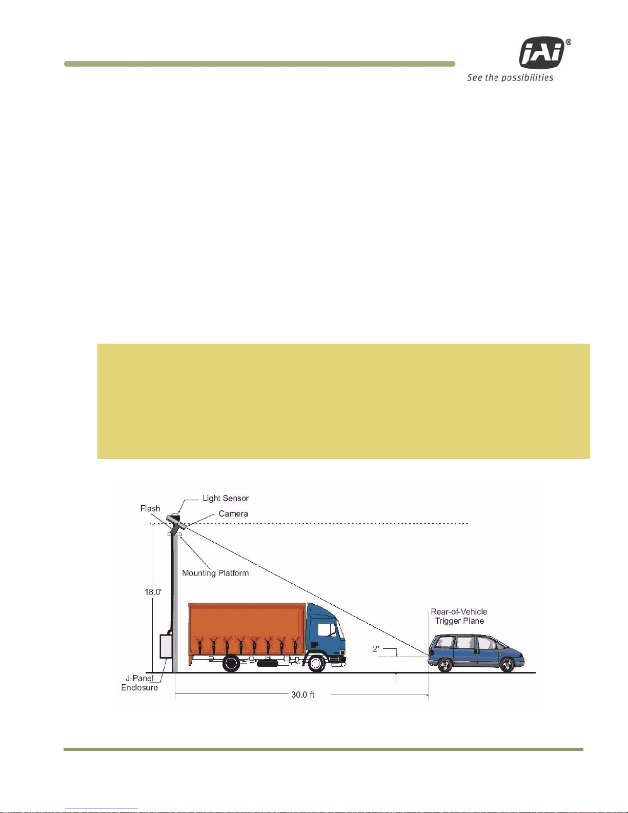
Imaging Subsyste m. There are two basic way s to position the camera: ov er the lane or beside the lan e . Figure 3
and Figure 4 depict a typical over-lane installation. Figure 13 and Fig u r e 14 depict a typical beside-lane camera
installation.
2.1.1 Over Lane Positioning
Over lane camera moun ting is always employed w h en the road width bein g monitored contains more than two
lanes of traffic, w h en a convenient overhe ad structure is already in place, or when prevent in g vandalism is a
paramount concern.
The VIS’s varifocal (zoom) lens is adjusted during installation to create 135 pixels across a 1
foot wide license plate (standard for US style of plates, may differ by region) placed 2 feet
above the ground level at the nominal trigger position (loop or light curtain, etc.). This
resolution maximizes license plate reader, vehicle matcher, or other image processing
techniques performance. The highest performance from the subsystem is achieved when the
variation in plate size is kept to within ± 5% which typically means that the vehicle trigger
accuracy should be within ± 1 foot (@ trigger plane defined by client.) at all speeds. Low
latency vehicle triggering is very important and should not be overlooked. Please contact JAI
for support on this issue.
Figure 3. Typical Over Lane Site Layout
Page 18

VIS-CAM Systems
6 Preparing for Installation
Figure 4. Typical Over Lane Site Layout Plan.
2.1.1 (a) Camera t il t considerations
The requirement to freeze the motion of high-speed vehicles limits how steep o r shallow the tilt angl e o f th e
camera may be. For e xample, it is important t o prevent the horizon from appearing in the image , and thereby
allowing the sun t o blind the camera. For over lane in stallations, a camer a tilt between 20° to 30° i s
recommended–with 25° be ing considered the opt im al angle. This angle of tilt is the best compromise b etween
minimizing visibilit y blockages caused b y c lo se l y sp ac e d vehicles and maximizin g plate visibility for plate
mounts that are slightly recessed or tilt e d downwards.
2.1.1 (b) Asynchron ou s triggering consider ations
When the VIS is operated in trigger mode, a vehicle detector is employed to cause the camera to capture an
image at the precise moment the vehicle is in the best position to image b oth the vehicle and its licen se p l ate.
The delay between the time the vehicle passe s the trigger position on the road and when the trigger signal
actually reaches the V I S must be kept to a minimum to prevent high-speed ve h icle s f rom moving out of the
area viewed by th e camera before the image is snapped.
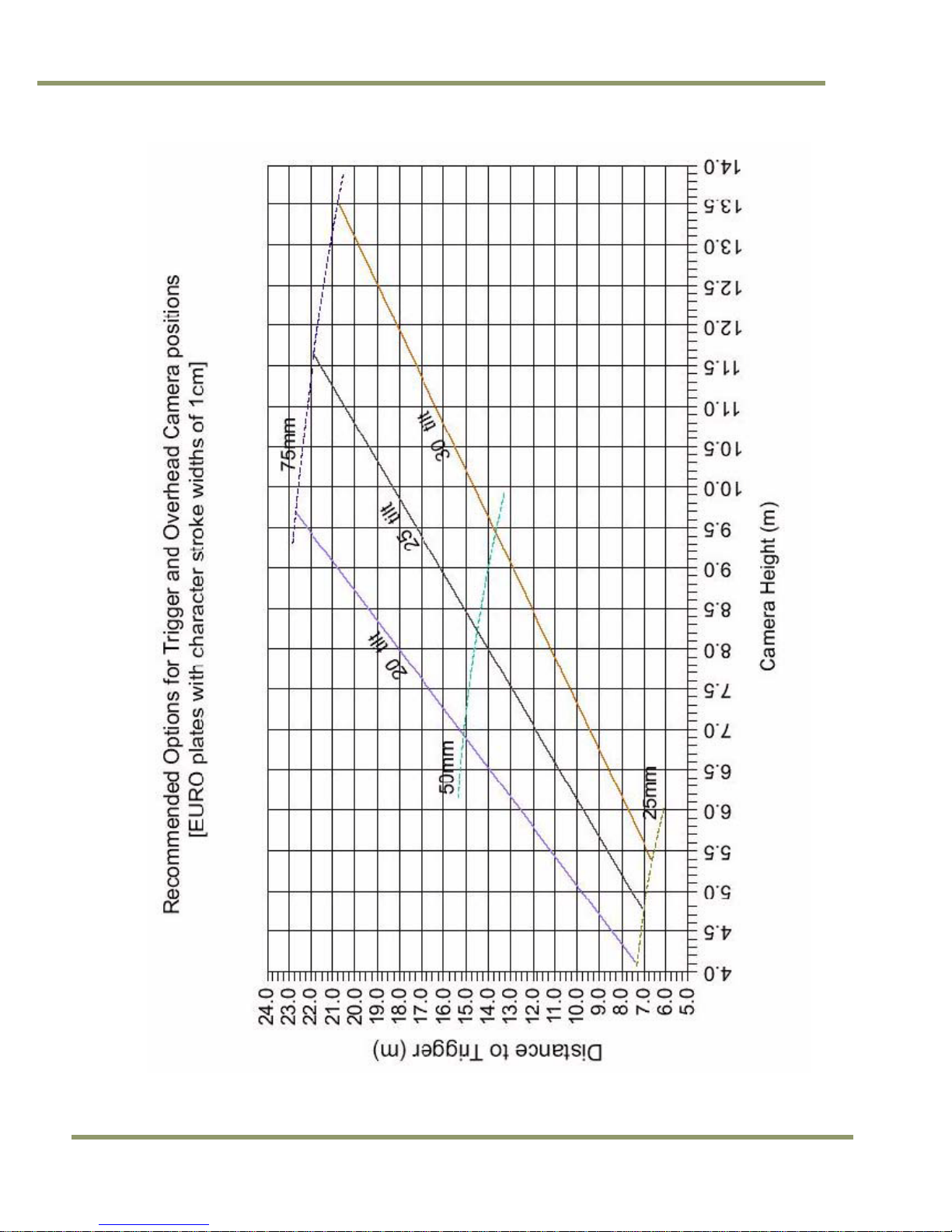
2.1.1 (c) Camera height versus trigger d istance considerations
It is critically important, to select the correct distance b e twee n t he camera and t he location on the road where
the camera is trigge r e d to capture an image. M in imizing the cost of inst al lation is usually also an imp ortant
concern. This means t hat whenever possible, it is best to use exist in g structures or prev iously in stalled
elements. The following ch arts (Figures 5 to 12) provide a wide range of trade-offs between camera heig h t and
trigger distance to enable the installer to se lect convenient came ra an d light sensor locations re l ative to
existing mounting structures and ve h ic l e trigger locations. Adhe rin g to the installation options provided in th e
installation charts, yields camera images that are generally su itable for automatic li cense plate reade rs (ALPR).
To use the charts correctly, please follow the steps below.
1. First measure the height above the road to convenient camera mounting locations.
2. Measure the distance along the road from directly beneath each candidate camera position to
convenient trigger locations.
3. Select the appropriate installation chart for either USA or European style license plates. To
obtain charts for license plates from other countries, please contact the JAI ITS division directly
at (+1) 408 383 0300.
Page 19

Preparing for Installation 7
VIS-CAM Systems
4. Plot the candidate camera-height / trigger-distance pairs on the chart and determine if the
selected location lies within the wedge of recommended values.
5. If several locations are suitable, choose the one that yields the greatest overall slant range
between camera and trigger location.
Page 20

VIS-CAM Systems
8 Preparing for Installation
Figure 5. VIS 300 U.S. Camera options chart.
Page 21

Preparing for Installation 9
VIS-CAM Systems
Figure 6. VIS 350 U.S. Camera options chart
Page 22

VIS-CAM Systems
10 Preparing for Instal lation
Figure 7. VIS 400 U.S. Camera options chart
Page 23

Preparing for Installation 11
VIS-CAM Systems
Figure 8. VIS 500 U.S. Camera options chart
Page 24
VIS-CAM Systems
12 Preparing for Instal lation
Figure 9. VIS 300 European Camera options chart.
Page 25

Preparing for Installation 13
VIS-CAM Systems
Figure 10. VIS 350 European Camera options chart
Page 26

VIS-CAM Systems
14 Preparing for Instal lation
Figure 11. VIS 400 European Camera options chart
Page 27

Preparing for Installation 15
VIS-CAM Systems
Figure 12. VIS 500 European Camera options chart
Page 28

VIS-CAM Systems
16 Preparing for Instal lation
2.1.2 Side of Road Installation
Figure 13. Typical side of road installation.
Figure 14. Typical side of road installation plan view with no canopy/overhead
structue.
Generally the f lash h e ad must be separated from the camera by a radial distance of at least three and a hal f
feet (1.2 meters).
If the flash is positione d cl oser to the camera, r e flections from the license plate will cause overexposure.
If possible, position the flash head in leve l with the reference plan e sh own in Figure 15. This plane is in level
with the top surface of the camera enclosure, but slices throug h t h e center of the le n s.
Page 29

Preparing for Installation 17
VIS-CAM Systems
Figure 15. Flash and camera distances.
Distance in
Feet
9720EN
2030EN
2076EN
1327EN
4032EN
MONO COLOR MONO COLOR MONO COLOR MONO COLOR MONO COLOR
3.5 1~3 2 1 2 1 3.5 1~3 3 1~3
Page 30

VIS-CAM Systems
18 Installing the Vehicle Imaging System
3 Installing the Vehicle Imaging System
The individual comp o n e n ts of the system is electr ical l y linked together as sh o w n in Figure 1, “VIS elemen ts”.
The VIS CAM camera h as c on n ections to the J-Panel an d an opt ion al Fl ash, Night Light and Laser Vehicle
Detector. The J-Panel has connection to two VIS CAM 300/400 cameras, one Traffic Light Sensor, a 24V Power
Supply, a Lane Controller, a RS485-to-ethernet converter for the light sensor signals, Trigger input, an
optionally second J-Panel and finally a gigabit Ethernet switch .
3.1 Installing the TNF-300 Traffic Light Sensor.
When installing th e Traffic Light Sensor e nsure the unit is positione d higher than either the camera or the flash
unit so the A-side is in direct sun whe n ever the targeted vehicles license plates are. See Section 2.1 for general
site layout guidel in e s.
It is extremely im p or tant the light sensor be p r operly positioned at t h e sit e . The light sensor must be placed so
that no shadows from su r ro u nding structure s ar e c ast on side A when the licen se plates being imaged by the
VISCAM are in direct su nlight.
Because sun angles at an y given site can change ac co rding to time of day and time of year, it is important to
verify that the proposed setup will function on the actual spot.
3.1.1 T o in stall the Traffic Light Senso r :
1. Disconnect Power
2. Loosen the four hex screws and remove the flange from the mounting base. See Figure 16.
Figure 16. Install the traffic light sensor.
Page 31

Installing the Vehicle Imaging System 19
VIS-CAM Systems
Figure 17. TLS-300 signal and power cable.
3. Route the Traffic Light Sensor end of the TLS-300 signal and power cable through the mounting
pipe and the flange (see Figure 18)
4. Screw the flange onto the pipe, finger-tight, to allow
subsequent minor adjustment
5. Attach the cable connector to the Traffic Light Sensor
6. Attach the Traffic Light Sensor body to the flange and
secure it with the four Allen screws
7. Orient the Traffic Light Sensor such that the white
reflectors are parallel to the trigger plane with side B
facing (visible from) the trigger plane
8. Route the free end of the cable to the VIS J-Panel in
accordance with the local code requirements
9. Connect the color-coded wires to J-Panel connector
X3 as described in Section 3.3, Section 6.4 and
Section 6.7. Make sure that no power is applied when
performing any wiring operation.
Figure 18. Installing the TLS-300 through
the mounting pipe and flange.
Table 1 Light Sensor Cables
PIN# Wire color Signal PIN# Wire col or Signal
1
White/green Heater gnd
10
White Gnd
2
Green
Heater gnd
11
-
nc 3 Red/blue
Heater +24V dc
12
-
nc
4 Blue/red Heater +24V dc 13 Brown D1-
5
- nc
14
White/brown D1+
6
Yellow
+24V dc
15
Orange
D0- 7 -
nc
16
White/orange
D0+
8
- nc
-
Black Shlds
9
- nc
Page 32

VIS-CAM Systems
20 Installing the Vehicle Imaging System
3.1.2 Optional Side Mount
1. Attach the pipe clamps approximately 6-inches apart on a vertical mounting surface as
shown in Figure 19.
2. Loosen the four Allen screws and remove the flange from the mounting base. Figure 16,
“Install the traffic light sensor”.
3. Route the Traffic Light Sensor end of the TLS-300 signal and the power cable through the
pipe and flange.
4. Screw the flange onto the pipe somewhat tightly to
allow subsequent minor adjustment
5. Place the pipe in the pipe clamps and tighten them
to secure the pipe to the vertical mounting surface.
6. Attach the Traffic Light Sensor body to the flange
and secure it with the four Allen screws.
7. Orient the Traffic Light Sensor such that the white
reflectors are parallel to the trigger plane with side
B facing (visible from) the trigger plane
8. Route the free end of the cable to the VIS J-Panel in
accordance with local code requirements
9. Connect the color-coded wires to the J-Panel
connector X3 as described in Section 3.3. Make sure
that no power is applied when performing any wiring
operation.
Figure 19. Pipe clamps should be
about 6-inches apart
on a vertical surface.
3.2 Installing the Camera(s)
In general, the camera(s) should b e aimed at the most likely c r oss-lane position of the v ehic le license plates.
See “Installation Pr e paration” in Section 2 f or general site layout guid elines. To install the camera(s):
1. Attach the camera mount to the camera enclosure using the included mounting bolts and washers.
Figure 20. Camera Installation
Page 33

Installing the Vehicle Imaging System 21
VIS-CAM Systems
2. Align the camera enclosure mounting surface with the hole pattern of the camera mount and
secure it to the camera mount with the five provided ¼-20 hex bolts.
3. Attach the camera, with mount, to the mounting structure. The hole pattern is shown in Figure 21
Below
Figure 21. Camera mount template.
4. Route the camera end of the camera cable according to the camera IAW local electrical code
Requirements
5. The jacket is removed from the cable in the camera end and the wires are stripped as shown in the
Figure 16 below. There are two sets of four twisted pairs. Four of the pairs are for ethernet signals.
These pairs are individually foil shielded and have a common braid shield. The other four pairs are
individually foil shielded without the common braid shield. The shield on the Ethernet pairs must
be run as close to the connector as possible. All wires must be stripped for insulation app. 7mm.
Figure 22. Camera cabling as it appears before electrical installation.
6. The cable is separated into the Ethernet part (with the braid shield) and the power and control
part (the rest). Each part is fastened with cable ties to the respective cable relief’s on the terminal
block X4 on the VIS-CAM I/O Board.
Page 34

VIS-CAM Systems
22 Installing the Vehicle Imaging System
Figure 23. Cable final wiring.
7. The wires are inserted into X4 as shown in Table 2 and Figure 18. A mounting tool for releasing the
spring enabling insertion of the wire is enclosed together with the connectors. (Mounting the wires
can be eased by separating the terminal block in the middle – just “break” it into two blocks of
eight terminals – and then re-join it when the wires are mounted)
Table 2 Electrical wiring for the VIS CAM installation.
X4 Pin #
Wire Color
Signal
Remarks
1
White/orange in Cat5e/6 cable
Ethernet A+
2 Orange in Cat5e/6 c ab l e Ethernet A-
3 White/green in Cat5e/6 cable Ethernet B+
4
Green in Cat5e/6 cab l e
Ethernet B-
5
White/blue in Cat 5e/6 cable
Ethernet C+
not used with VIS CAM
6 Blue in Cat5e/6 cable Ethernet C- not used with VIS CAM
7 White/brown in Cat 5 e /6 cable Ethernet D+ not used with VIS CAM
8
Brown in Cat5e/6 cable
Ethernet D-
not used with VIS CAM
9
Black
Gnd
20 AWG
10 Red +24V dc 20 AWG
11 Red Vinit+ Trigger signal, 24 AWG shielded
12
Black
Vinit-
Trigger signal, 24 AWG shielded
13
Brown
RS485D+
Lane Controller, 24 AWG shielded
14 Black RS485D- Lane Controller, 24 AWG shielded
15 Orange RS485D+ Lane Controller, 24 AWG shielded
16
White
RS485D-
Lane Controller, 24 AWG shielded
Page 35

Installing the Vehicle Imaging System 23
VIS-CAM Systems
Figure 24. Properly wired X-4 connector.
8. The cable is mounted in the cable entry on the back side of the camera as shown in the Figure 19
below. The rubber bushing is mounted around the jacket and the metal brace is mounted around
the shield securing proper electrical connection from the shield to the metal housing (se figure
Figure 19).
Figure 25. Back of the video camera.
For a detailed descrip tion of the VIS CAM in t erface please refer to S e e “ Ap pendix A: Camera Functional and
Connector Description” in this manual.
Page 36

VIS-CAM Systems
24 Installing the Vehicle Imaging System
3.3 Installing the J-Panel
The J-panel layout is shown in Appendix A, See “Connection requirements.”. This Ap pendix has a detailed
description of the J-Panel function and connectors.
3.3.1 X1 a nd X2 VIS
The VIS CAM connections to the J-Panel are shown in Table 3 and Figure 20
Table 3 VIS CAM connections to the J-Panel.
X1, X2 Pin #
Wire Color
Signal
Remarks
1 White/orange in Cat5e/6 cable Ethernet A+
2 Orange in Cat5e/6 c ab l e Ethernet A-
3
White/green in Cat5e/6 cable
Ethernet B+
4
Green in Cat5e/6 cab l e
Ethernet B-
5 White/blue in Cat 5e/6 cable Ethernet C+ not used with VIS CAM
6 Blue in Cat5e/6 cable Ethernet C- not used with VIS CAM
7
White/brown in Cat 5 e /6 cable
Ethernet D+
not used with VIS CAM
8
Brown in Cat5e/6 cable
Ethernet D-
not used with VIS CAM
9 Black wire in Red/Black p air Gnd 20 AWG
10 Red wire in Red/Black pair +24V dc 20 AWG
11
Red wire in Red/Black pair
Vinit+
Trigger signal, 24 AWG shielded
12
Black wire in Red/Black pair
Vinit-
Trigger signal, 24 AWG shielded
13 Brown wire in Brown/Black pair RS485D+ Lane Controller, 24 AWG shielded
14 Black wire in Brown/Black pair RS485D- Lane Controller, 24 AWG shielded
15
Orange wire in O r an ge/White pair
RS485D+
Lane Controller, 24 AWG shielded
16
White wire in Orange/White pair
RS485D-
Lane Controller, 24 AWG shielded
Page 37

Installing the Vehicle Imaging System 25
VIS-CAM Systems
Figure 26. VIS CAM connections.
3.3.2 X3 , X7 Traffic Light Sensor
The Traffic Light Sensor TLS-300 connection to the J-Panel is shown in Table 4 and Figure 21.
Table 4 TLS 300 to J-Panel connections.
X3 Pin X
Signal
Description
Connection to Light Sensor Cable w i r e col or
1
+24V dc
Power output
Yellow
2 Gnd Power return White
3 D0+ RS485 databus D0+ White/orange
4
D0-
RS485 databus D0-
Orange
5
D1+
RS485 databus D1+
White/brown
6 D1- RS485 databus D1- Brown
X7 Pin X
1 Heater +24V dc
Power output
Red/blue and Blue/red
2
Heater gnd
Power return
White/green and Green
Page 38

VIS-CAM Systems
26 Installing the Vehicle Imaging System
Figure 27. TLS 300 to J-Pa ne l wiring.
3.3.3 X6 P o w e r Input Connector
The Power Input connection to the J-Panel is shown in Table 5 and Figure 22.
The maximum power to a J-Panel is:
Camera #02.0A
Camera #1 2.0A
Traffic Light Se n sor 2.0A
RS485-to-Ethernet conv0.3A
Total6.3A
Table 5 Power input to the J-Panel
X6 Pin #
Signal
Description
Connection to
1
+24V
+24V dc
24V DC power supply + output
2
GND
+24V return
24V DC power supply return
Page 39

Installing the Vehicle Imaging System 27
VIS-CAM Systems
Figure 28. X-6 Power input connection.
3.3.4 X8 LS RS485 Out Connector
The RS485 output from the Light Sensor to the RS485-to-Ethernet converter connector is X8. The con ne ct ions
from X8 to the converter are shown in Table 6 and Figure 23
Table 6 X8 to converter connector
X8 Pin #
Signal
Description
Connection to RS4 8 5 -to-Ethernet converter
1
+24V dc
24V Power output
V+ power input
2
Gnd
Power return
V- power input
3 +12V dc 12V Power output
4
Gnd
Power return
5 D0+
RS485 databus D0+
D+ Port 2
6
D0-
RS485 databus D0-
D- Port 2
7 D1+ RS485 databus D1+ D+ Port 1
8
D1-
RS485 databus D1-
D- Port1
Page 40

VIS-CAM Systems
28 Installing the Vehicle Imaging System
Figure 29. Wiring for the X8 to converter connector.
Up to four cameras can be connected t o on e Ligh t S e n sor using one Moxa Nport 5232 Device Server. If more
than four cameras need to be connected to the same Light Sensor please refer to “Appendix E: Moxa N-Port
5232 Configuration” in t h is M anual.
3.3.5 X1 4 Trigger Input Connector
The Trigger input connection to the J-Panel is connector X14. The connections are list ed in Table 7
Table 7 Trigger input connector.
X14 Pin #
Signal
Description
Connection to
1
Trig0+
Positive Trigger in put to camera 0
Trigger device positive terminal
2
Trig0-
Negative Trigge r in p ut to camera 0
Trigger device ne gative terminal
3 Trig1+ Positive Trigger in put to camera 1 Trigger d evic e p ositive terminal
4 Trig1- Negative Trigger inp u t to camera 1 T rig g e r d evice ne g at iv e terminal
3.3.5 (a) Trigger polarity
The switches S3 and S5 se ts the trigger polarit y :
If the trigger sig n al is normally low (no voltag e at t r igg er input) the switch shall b e in position
Arrow up - positive going
If the trigger sig n al is normally high (voltag e at trigger input) the switch shall be in position
Page 41

Installing the Vehicle Imaging System 29
VIS-CAM Systems
Arrow down – negative g oing
As a guideline the t wo LEDs marked TRIG-0 and TRIG-1 shall be off wh e n no t r igger pulse is present.
3.3.5 (b) Test Trigger
Activating switches S1 and S4 generates a tr igger pulse for test purposes. Only one trigg e r pu lse is generated
each time the swit ch is activated.
The duration of t h e t r igger pulse is approximately 4 ms.
The trigger indicator LEDs flash when the test trigger switc h is act iv ated.
Figure 30. Test trigger
3.3.6 X15 Lane Controller Connector ( X4 a nd X5)
The Lane Controller connection to the J-Panel is connector X15. The connections are list e d in Table 8 .
Table 8 X15 Lane Controller
X15 Pin #
Signal
Description
Connection to
1
D0+
RS485 databus D0+
Lane Controller databus 0+
2 D0- RS485 databus D 0- L ane Controller databu s 03 Gnd gnd gnd
4
D1+
RS485 databus D1+
Lane Controller databus 1+
5
D1-
RS485 databus D1-
Lane Controller databus 1-
It is possible to have o n e Lane Controller connect e d to several cameras or one L an e Controller to each camera:
One Lane Controller for two or more cameras
1. The Lane Controller is connected to the X15 pin 1 and 2 (no connections to pin 4 and 5)
2. Switch S2 position “OPEN”
3. The Lane Controller can be connected to more J-Panels by connecting RJ45 patch cables between
connector X4 and connector X5 on the next J-Panel (and from X4 on the next J-Panel to X5 on
the third J-Panel). Switch S2 on the other J-Panels must also be in the “OPEN” position.
Two Lane Controller to two cameras
1. The Lane Controller for camera 0 is connected to X15 pin 1 and 2
2. The Lane Controller for camera 1 is connected to X15 pin 4 and 5
3. Switch S2 position “TERM”
4. Do not connect any cables to X4 and X5
Page 42

VIS-CAM Systems
30 Installing the Vehicle Imaging System
Figure 31. Two lane controller.
3.4 Illumination Options
3.4.1 Installing the TNF-31 Flash
The connection to the Flash unit in the VIS CAM 300 is shown in Table 9 and Figure 26.
Figure 32. TNF-31 flash unit
Table 9 Flash unit connection in VIS CAM.
Pin
Signal
Description
Connection to
1 I/O Gnd IO Board Gnd Pin 2 when no power is availa b l e from the flash
2 Gnd Flash Gnd Flash ground (negative power term in al)
3
Out
Strobe out
Strobe input on flash unit
4
Stat
Strobe status
Status output from flash unit
5 FPWR Flash power Power from flash to out p u t circuit on I /O Board
6 24V IO board 24V (Fused0.5A) Pin 5 when no p o w er is available from the flash
The cable from th e fl ash unit is connected to th e V IS CAM I/O Board as shown in figu re 3.17 and 3.18. There ar e
two examples shown: one where the ou t p ut circu it on t h e I/O Board is pow e re d f r om t h e flash unit and one
where the output circuit is powered from the I/O Board.
It is recommended that I/O Board output c irc u it be powered from the flash unit in order to obtain galvanic
isolation between the two units. In cases w h ere this is not possible (suc h as when using mains supp lied flash
units) power is tak en from the I/O Board.
The cable must be shielded and the shield connected to the metal at the cable entry in the camera house. The
switch labeled S3 on the VIS CAM I/O Board must be in position “NIGHT L” (away from connector X5 as show n
below).
Page 43

Installing the Vehicle Imaging System 31
VIS-CAM Systems
Figure 33. S3 switch setting
Figure 28 shows how to c on n ect to an AC powered Flash u n it with the I/O Board inter face electronics internally
powered by the I/O Board. The Flash AC power connection is not shown.
Figure 34. Connecting an AC flash.
Other Flash connection examples are foun d in “ Appendix A: Camera Fun ctional and Connector Description”.
The VIS CAM has an in t erface for two flashes. W hen this option is selected (S3 position “FLASH 2”) and the
other flash is connected to connector X6, the two flashes fire alternately. Please refer to “ Appendix B: J-Panel
Functional and Conne c t o r D escription” for det ail s.
3.5 Trigger Options
3.5.1 Installing The Laser Vehicle Detector
The connection from the Laser Vehicle Detector to t he VIS CAM 300 is sho w n in Figure 29 and Tab l e 1 0
Page 44

VIS-CAM Systems
32 Installing the Vehicle Imaging System
Figure 35. Connection for LVD to VIS CAM.
Table 10 Wiring for LVD to VIS CAM.
X7 Pin # Signal Description C onnect ion to
1 24V (Fused 0.5A) Power to laser Laser power in p ut
2
Gnd
Power gnd
Laser ground
3
Trigger
Trigger from laser
Trigger out on laser
4 RS485- Transmit to laser Receive input on l ase r
5 RS485+ Receive from laser Transmit output on lase r
6
Gnd
Communication gnd
Communication gnd on laser
7
nc
No connection -
-
8 nc No connection -
The cable must be shielded and the shield connected to the metal at the cable entry in the camera house.
The switch S3 and/or S5 on the J-panel must be in position “positive going” (push e d towards X1/X2) to enab l e
the laser trigge r in p ut on the IO Board.
Page 45

System Set-Up 33
VIS-CAM Systems
4 System Set-Up
This section provides a generic procedure f or align ing on e or more of the VIS CAM cameras and their associated
equipment at a site. If you received a specific installation manual f r om J A I for your project th e n foll ow those
instructions inste ad of the procedure described here.
The example inst al l at io n process described in th is section assumes that:
• The cameras are being mounted on an overhead structure directly over the lane(s) being
observed. The process for aligning a camera mounted at the side of a lane is essentially the
same as aligning a single camera mounted directly over the lane.
• The site employs an accurate vehicle detection device that outputs a discrete TTL signal to the
VIS system whenever the back (or front) of a vehicle crosses a fixed line across the road. This
line is referred to as the “trigger line” in this document. Examples of such triggering devices
are: Peak’s trafficLoop, STI’s Vehicle Detector light curtain, and JAI’s Laser Vehicle Detector.
• License plate reading or vehicle matching is performed on the images produced by the VIS
system. In these cases, precise location and alignment of the cameras is critical to project
success. If the VIS images are only for human interpretation, then achieving the exact camera
alignment is much less critical.
• The installer is familiar with using the ENSetup program supplied by JAI. Please refer to the
ENSetup Program User’s Guide if you are unfamiliar with this software. JAI offers engineering
support and software tools to help select the optimum camera and trigger locations to meet
your specific project needs. Contact ITS Engineering Support at (408) 383-0300 for further
information about obtaining JAI assistance.
4.1 Preparation for Alignment
4.1.1 Pre-Alignment Checklist
• Make sure you have a JAI supplied setup computer with the ENSetup program installed.
• The Setup computer needs to have an Ethernet network adapter installed (preferably 1 Gigabit
Ethernet Adapter) and the TCP/IP network configured with the correct IP-address, subnet-mask
and default-gateway.
• The Setup computer and the cameras need to be on the same subnet. The cameras are shipped
with the standard IP-address “10.0.0.65” and subnet-address “255.255.255.0”, and the Setup
computer needs to be assigned an IP-address “10.0.0.xx” in order to automatically discover the
cameras using the ENSetup program (NB! “xx” must not be “65”).
• All cameras have to be given unique I P -addresses before the alignment begins. This is done using
the ENSetup application.
• Confirm all VIS CAM components and cables are properly connected.
4.1.2 Select a Suitable Vehicle, License Plate, and Plate Stand for the Setup
To accurately set u p t he Vehicle Imaging Sub sy stem, the system installe r s n eed access to:
Page 46

VIS-CAM Systems
34 System Set-Up
1. A vehicle that can be temporarily parked on the road
2. A plate that is:
a. typical in size and color for the site
b. clean, flat and in “like new” condition
3. An adjustable plate stand that allows the plate to be mounted in a vertical plane, at various
heights above the road, and at variable roll angles. The stand must allow the plate to be placed
at both the nominal plate height and the minimum expected plate height. The stand must also
allow the plate to be rolled at least + or – 10 degrees from horizontal but held firmly in place
once a specific roll angle is selected. The stand should be heavy enough so that the wind will
not blow it over or move it.
Table 11 Typical minimum plate heights and nomina l pl ate heights:
Plate Height
Front of Vehicle
Back of Vehicle
minimum (bottom edge)
8in or 20cm
15in or 38cm
nominal (middle) 16in or 40cm 24in or 60cm
4.1.3 Select the Camera to Align
• If the site employs a single camera per lane, then you can choose any lane to start the
alignment procedure.
• If the site employs multiple cameras regularly spaced across a roadway to provide continuous
fieldof- view coverage from edge to edge, select one of the cameras at either edge of the
roadway to be the first camera to align.
• Align all remaining cameras in order from the first camera aligned to the last camera at the
other side of the roadway. The next camera aligned is always the one adjacent to the camera
most recently aligned.
4.1.4 V alidate the Installation Geometry
The VIS cameras and vehicle trigger line sh ou l d have been installed at the locations agreed to by you and JAI.
Typically JAI util izes a specially developed Excel worksheet to confirm the suitability of the equipment
placement at the site from an image processing perspective. See Figure for an example worksheet. However,
equipment is often not located where the worksheet specifies. It is therefore imperative that the actual
equipment layout at any given site be measu r e d to verify that the came ras and trigger are located at the
desired locations relative to each othe r. If necessary, move t h e cam e r a/trigger positions until the distances
required in the w or ksheet are met. If it is no t p ossib l e t o move the equipment t o th e r e qu ired locations, then
the impact of any ch an ges to the subsequen t image processing must be assessed. Enter the actu al c ame r a
locations into the I nput section of the JAI w o rksheet and then note the changes in the Results section. If there
are any questions abou t the suitability of a specific camera/trigger layout, contac t your JAI representat iv e for
advice.
4.1.5 Edit the alignment settings on the Setup Computer
In order to carry out the alignment properly, the ENSe t u p program has to be conf ig u red with t w o v alue s f rom
the worksheet. S e e t he E N S e tu p P r ogram User’s Guide (Video W in dow Setup section) f or details on changing
Video Window properties.
Using the ENSet up p r ogram, make sure the “tilt line” and “plate num cols” items on your Portable Setup
computer are exactly the same as the measu r e m e n ts, including the prop e r plate size parameters measu red in
Section 4.1.4, “Val idate the Installation Geometry,”. All oth e r c ame r a settings should already be correct for
the site installation , but it is a good idea to v erify that this is true b e fore proceeding. The Set u p Comp uter is
now properly configured to support lens adjustments and camera aiming.
Page 47

System Set-Up 35
VIS-CAM Systems
4.1.6 Co nne c t th e Setup Co mputer to the Camera
• Position the Setup Computer next to the camera being aligned. If the alignment is conducted in
bright sunlight, shield the monitor screen with a hood to make it visible. Make sure that no
portion of the computer or cables interfere with the camera’s view of the road.
• Connect the Setup Computer’s network adapter with the camera network. This can be done
directly to the I/O boards X1 and X3 connectors or using a local Ethernet switch. It is preferable
to use a local Ethernet switch instead of a local direct connection to the I/O board. A direct
connection between the Setup computer and the camera will disconnect the camera from the
site LAN and thereby disconnect the light sensor as well.
Figure 36. Example of a network connection using a local switch.
The network connection between the Setup comput e r an d the c amera can be established u sin g a local switch.
Two separate ports of the Ethernet Switch are connect ed directly t o t h e I/O b oard conn ectors X1 and X 3. The
Setup computer is then also connecte d to one of the free ports on the switch. If the switch is running on 24V
dc, the I/O board is capable of supplying up to 0.5A on connector X15 located next to X1 and X3. The pin
marked with #1 on X15 is +24V d c.
Page 48

VIS-CAM Systems
36 System Set-Up
4.1.7 Drive and Park the Setup Vehicle Correctly
• Drive the setup vehicle slowly towards the trigger line through the center of the cameras field
of view in the same manner (heading) as a typical driver would occupy this lane.
Note: This is important, make sure that the vehicle is driven exactly the same way as the average
driver would through the section of roadway being viewed by the camera.
• Stop the vehicle approximately one foot (0.3 meter) past the trigger line. Make sure that the
vehicle is parked aimed in the same direction as the average driver would point their car if they
were driving through this section of roadway.
• To help the driver of the vehicle properly aim the car while driving, instruct him (or her) to
always look forward down the road as they would normally. Use a sound to signal the driver
when to stop.
4.1.8 Properly Position the License Plate Stand
Using your portabl e plate stand, position a lice n se plate:
• at the minimum expected trigger distance from the camera.
• at the minimum expected plate height above the road.
• at the location along the trigger line where the center of the horizontal field-of-view of this
camera is desired.
Rotate the plate on the stand until the top and bottom edges are level with the vehicle parked behind the
trigger line (to within a + or – a couple of degrees). Secure the plate on the plate stand so that the adjustments
you have just made do not change.
4.1.9 P e rf o rm Initial Lens Adjustment and Camera Aiming
1. Back away all of the thumbscrews on the lens holder until they do not touch the knurled
adjustment rings on the lens.
2. Make sure the lens aperture adjustment is fully open (rotate the third ring from the front of the
lens fully counter-clockwise until it stops at the f1.2 setting). Secure the thumbscrew that lines
up with the aperture ring until it just presses against the ring. Next tighten the thumbscrew that
lines up with the knurled ring closest to the camera body until it just presses against the lens.
Do not tighten any Lens Holder thumbscrews beyond a slight pressure against the lens.
3. Loosen the roll, pan, and tilt bolts on the JAI camera mounting head until each axis can be easily
adjusted by hand but any particular setting will stay in place after you let go.
4. Power on the Setup computer and then start the ENSetup program. Press the “Video Window”
button to open the Video Window and then select the camera for adjustment from the tree-view
on the left side of the window. Press the “Live” button in the toolbar to start the video
streaming. Press the “Tilt Line” button to show the alignment guidelines. The “Tilt Line” can be
moved using the mouse, or if the “Tilt Line” is selected, using the arrow-keys.
5. Interactively adjust the roll, pan, and tilt of the camera mount and the lens zoom and focus
rings:
6. Adjust the lens focus ring (and camera pan and tilt as necessary) to obtain a focused image of the
plate on the plate stand. If at any time you cannot fully focus the plate because the focus ring
on the lens has reached the end of its turning movement, perform the back-focus procedure
described in the JAI document titled “Zoom Lens Back-Focus Procedure.”
Page 49

System Set-Up 37
VIS-CAM Systems
7. Adjust the lens zoom ring to obtain a plate width approximately equal to the distance between
the short vertical sizing marks that appear above the tilt line. Readjust focus as necessary. See
Figure 31 for more information.
Figure 37. Initial Camera Alignment Display example.
8. Turn on the “Roll Bar” display on the Setup computer and then roll the camera mount until the
horizontal bumper and trunk seams on the vehicle appear perfectly level with the horizontal
line of the display. Use one 7/16" closed-end wrench on the roll gear to fine-tune the roll angle.
Hold the roll position with the wrench while you use a second wrench to gently tighten the
other roll bolts. Then apply both wrenches to corresponding bolts on opposite sides of the
mount. Twisting in opposite directions to fully secure all of the roll bolts. This approach
prevents the roll adjustment from changing while you tighten the bolts. See Figure 32.
Page 50

VIS-CAM Systems
38 System Set-Up
Figure 38. Roll Bar Display example.
Pan the camera mount until the plate stand is centered under the default position of the vertical line in the
middle of the “Roll Bar” display. Securely tighte n the pan bolt. Be caref u l n ot t o change the p an of the camera
while you tighte n the bolt. Oppositely twist in g two 9/16" closed-end wrenches is recommended (one f o r the
bolt head and one for the nut) to help prevent the pan from moving while you tighten the bolt.
Switch back to th e “T il t Line” display. Tilt the camera mount until the plate is positioned j u st above the tilt
line. Re-adjust the zoom as necessary until the plate just fits in between the zoom markers on the “Tilt Line”.
Changing zoom usual ly requires that the tilt adjustment be modified also . Do not tighten the Tilt bolts until
after the final lens adjustment. See Figu r e 33.
Page 51

System Set-Up 39
VIS-CAM Systems
Figure 39. Readjustment of camera tilt and zoom display.
The camera mount and lens are now ready for final adjustment.
4.1.10 Finalize Lens Adjustments and Camera Aiming
4.1.10 (a) Reposition the License Plate Stand at the Nominal Trig ger Line
Use your portable plate stand to position the license plate:
1. at the normally expected (nominal) trigger distance from the camera.
2. at the nominal plate height above the road.
3. at the location along the trigger line where the center of the horizontal field-of-view of this
camera is desired.
Rotate the plate on the stand until the top and bottom edges are perfectly level with the vehicle parked
behind the trigger line. Secure the plate on the plate stand so that the adjustments you have just made do not
change.
4.1.10 (b) Perform Fin al C am era Mount and Lens Adjustments
The final focus adjustment is facilitated u sin g the “Focus Bar” display on the Video Window. Press the “Focus
Bar” button on the t o olbar. This displays a “Focus Bar” marker on the Video Window that will open a separate
“Focus Bar” window where the pixel-v al u e s taken from the focus bar mark e r is displayed. The “Fo cu s Bar”
marker cam be moved with the mouse pointer, or if the “Focus Bar” marker is selected, using t h e arr ow-keys.
1. Position the “Focus Bar” marker directly over the license plate.
Page 52

VIS-CAM Systems
40 System Set-Up
Figure 40. Focus Bar marker display.
2. Adjust the lens zoom ring until the plate width just barely fits in between the short vertical zoom
markers on the display.
3. Have your assistant tape the lens front-focus chart to the stand so that it appears in-between the
zoom markers. Make sure the black and white bars are vertical in the image.
4. Carefully adjust the lens focus ring until the focus bar waveform display is maximized in
amplitude spread. The “Focus percentage” display shown on the left side of the “Focus Bar
Waveform” window should then be maximized when the picture has got the best focus. If
necessary, readjust the zoom and focus until the width of the plate is just inside the zoom
markers and the waveform spread of the bars is maximized.
Page 53

System Set-Up 41
VIS-CAM Systems
Figure 41. Focus Bar Waveform display.
5. Gently snug the zoom and focus lens holder thumbscrews against the lens without changing any of
the lens settings.
6. Uncover the license plate by removing the lens focus chart.
7. Use the mouse to move the waveform cursors to the top and bottom of the waveform amplitude
variation. The “Black Cursor” is located at the bottom of the waveform display, and the “White
Cursor” is located on the top of the waveform display.
8. Verify that the waveform amplitude variation (for characters in both direct light and shadow, if
possible) is at least 25 and that no portion of the waveform fully saturates either black or white.
Page 54

VIS-CAM Systems
42 System Set-Up
Figure 42. Focus Bar Waveform Display with waveform cursors.
9. Use one hand to carefully hold the focus ring of the lens in place while you rotate the filter ring
on the very front of the lens with your other hand. Turn the filter ring until the white mark on
the ring is oriented straight up (or down). Secure the filter ring in place with a small dab of RTV
glue.
10. Printout the image of the screen using the “File -> Print…” menus on both the “Video Window”
and the “Focus Bar Waveform” windows to document the settings. If no printers are connected,
the “PDFCreator” printer driver can be used to save the pictures as PDF-files.
11. Have your assistant move the plate stand back to the near trigger line and re-position the plate
at the minimum plate height.
12. Drive the setup vehicle slowly towards the trigger line in the same heading as normal traffic
flow and center it directly between the camera being aligned and the adjacent camera that has
already been aligned. Marking the position halfway between adjacent cameras at the trigger
line with some marker is advisable to help the driver properly aim the vehicle.
13. Park the vehicle at the location where it just barely causes the trigger to cause an image to be
captured. For loop triggers, park the vehicle where a vehicle would normally be located when
the loop trigger signals the VIS to capture an image.
4.1.11 Flash Head Alignment
The following section p r ovides a general procedur e to align the VIS flash head. Be sure to follow any spec if ic
alignment procedure provided with your system.
Align the flash he ad at n ight and after aligning the cameras. Park a light col or e d vehicle underneath the
camera and where the vehicle detector triggers the camera.
Page 55

System Set-Up 43
VIS-CAM Systems
• Press the “Repetitive Trigger” button on the ENSetup toolbar. This will trigger the camera every
second. Make sure that the “Ethernet” external hardware trigger is enabled in the “Camera
Properties” section “2 – Trigger”, property “External Trigger Source”.
• Adjust the flash head tilt and pan control until the entire back of the vehicle is well illuminated.
If necessary, adjust the flash-head pan control to center the flash beam over the vehicle.
• If the flash illumination is too bright for your installation, contact JAI for instructions on how to
adapt VIS system parameters to reduce sensitivity to nighttime illumination.
Repeat pressing the “Repetitive Trigger” button on the ENSetup toolbar to stop flash firing. Repeat the above
steps for each camera/f l ash.
Page 56

VIS-CAM Systems
44 Appendix A
5 Appendix A: Camera Functional and Connector Description
The camera has connections to the EN J-Panel, Light sensor, Flash, Night Light and Lase r Veh ic le Detector as
shown in the system overview Figure 37.
Appendix A descr ib es the camera connectors for t hese units, the signal specifications, output circuits and test
facilities. It al so c ov ers cable requirements.
Figure 43. Connection requirements.
Page 57

Appendix A 45
VIS-CAM Systems
5.1 I/O Board Layout
Connections to the camera are made through the EN I/O Board located in the back of the camera housing.
Figure 38 shows the b oar d lay out.
Figure 44. Component layout of the EN board.
Page 58

VIS-CAM Systems
46 Appendix A
5.2 X4: I/O Board Connection to J-panel
Figure 45. Board connections
5.2.1 Functionality
Power and data conn e c tion to the camera. T h e 24V powe r supply f or all camera fu n ct ions ( C amera, I /O Board,
light and heater s), Ethernet and RS485 d at a com mu nication is connect ed using this connect or .
5.2.2 Connector specification
Connector type:16 pole WAGO pluggable terminal block
Connector on board:WAGO 734-246
Cable part:WAGO 734-216
5.2.3 Connector signal specifications
5.2.3 (a) Lane Controller interface
Description
RS485 two wire half-duple x multi-drop commu n icat ion network. The I/O Board has connec t ions t h at allow f or
daisy chain configu r ation. The two sign al pairs (RS485D+ and R S4 85D-) can be reversed. The signal is terminated
on the J-Panel.
Signal levels:
Standard RS485 communication le v e l s. C ommon mod e ran g e –7 t o +12V .
Page 59

Appendix A 47
VIS-CAM Systems
Electrical interface on the I/O board:
Figure 46. Interface drawing.
5.2.3 (b) Trigger input
Description
The trigger input is balanced and the inp u t circ u it is a RS485 receiver.
Signal levels
The signal levels ar e st andard RS485 signals. T h e sp ecification below is t aken from Linear Tech n ologies
datasheet for LTC1480:
The common mode range is –7 to +12V.
5.2.4 Electrical interface on the I/O board:
Figure 47. Electrical interface
5.2.4 (a) Ethernet Interface
Page 60

VIS-CAM Systems
48 Appendix A
Description: 100 Mb Ethernet interface . The signal must be conne cted to a gigabit Et hern et switch for be s t
performance. The cable must be a Cat 5e or preferably a Cat 6 cable . The wire color marking on the PCB is
standard Ethernet wire colors.
5.2.4 (b) Power input
Voltage24VDC±20%
Current0.3A with heaters and LED light off
Max currentinrush app 2.5A
Heaters on 1.3A totally
5.2.5 Connector physical Interface
Figure 48. Physical interface table.
Pin Signal Description
Connection to
J-Panel X1
or X2
Remarks
1 Ethernet A+ Ethernet signal t o gigabit switch pin 1 Cat5e/6 cable white/orange
2
Ethernet A-
Ethernet signal to gigab it switch
Pin 2
Cat5e/6 cable orange
3
Ethernet B+
Ethernet signal t o gigabit switch
Pin 3
Cat5e/6 cable white/green
4 Ethernet B- Ethernet signal to gigabit switch Pin 4 Cat5e/6 cable green
5 Ethernet C+ Ethernet signal to gigabit switch Pin 5
Cat5e/6 cable white/blu e
not used with VIS CAM
6 Ethernet C- Eth ernet signal to gigabit switch P in 6
Cat5e/6 cable blue
not used with VIS CAM
7 Ethernet D+ Ethernet signal to gigabit sw itch Pin 7
Cat5e/6 cable white/brow n
not used with VIS CAM
8 Ethernet D- Ethernet signal to gigabit sw itch Pin 8
Cat5e/6 cable brown
not used with VIS CAM
9
Gnd
Power ground
Pin 9
Black wire in Red/Black p air
10
+24V dc
Supply voltage
Pin 10
Red wire in Red/Black pair
11 Vinit + Balanced trigge r pulse positive Pin 11 Red wire in Red/Black pair
12 Vinit - Balance tripper pulse negative Pin 12 Black wire in Red/Black pair
13
RS485D+
RS485 Data+ for Lane Controller
Pin 13
Brown wire in Brown/Black pair
14
RS485D-
RS485 Data- for Lane Controller
Pin 14
Black wire in Brown/Black pair
15 RS485D+ RS485 Data+ for Lane Controller Pin 15 Orange wire in Orange/White pair
16 RS485D- RS485 D at a- for Lane Controller Pin 16 White wire in Orange/White pair
Page 61

Appendix A 49
VIS-CAM Systems
5.2.6 Typ ical wiring diagram.
Figure 49. Category 5 or 6 wiring diagram.
5.3 I/O Board Flash Connection
Figure 50. Flash connections.
5.3.1 Functionality
Output to flash unit. This output is used when only one flash unit is connected. The output is galvanically
isolated using an optocoupler. The isolat e d part of the electronics on th e board can be powered from the flash
unit or from the I/O Board using a 24V DC output on the connector.
5.3.2 Connector specification
Connector type:6 pole WAGO pluggable terminal block
Connector on board:WAGO 734-236
Cable part:WAGO 734-206
Page 62

VIS-CAM Systems
50 Appendix A
5.3.3 Connector signal specifications
Description
Logic inverter powered by 5V drives the ou t put. The inverter is a HCMOS type 74AHC14.
Output signal specification
Signal amplitude 5V TTL
Output impedance100 Ω
Pulse width5 ms ± 1 ms
Signal polarityact ive high
External power requirement
Voltage8-26V DC
Currentmax 25μA
Electrical Interface on the I/O board:
Figure 51. I/O board electrical interface. Test
A push button switch S1 can be activated f or g ene ration of an output pulse for test purposes. The flash output
is high as long as the sw itch is activated. T he sw itch is located as shown on Figure 52:
Figure 52. Switch location.
5.3.4 Connector physical Interface
Table 12 Wiring diagram.
Pin
Signal
Description
Connection to
1
I/O Gnd
IO Board Gnd
Pin 2 when no powe r is available from the flash
2 GND Flash Gnd Flash ground (neg ative power terminal)
3
Out
Strobe Out
Strobe input on flash unit
4
Stat
Strobe status
Status output from flash unit
5
FPWR
Flash power
Power from flash to outpu t cir cu it on I/O Board
6 24V IO board 24V ( Fu se d 0.5A) Pin 5 when no power is available from th e flash
Page 63

Appendix A 51
VIS-CAM Systems
5.3.5 Ty pical Wiring Diagram
Figure 53 shows how to connect to the DC Flash unit having the I/O Board electronics powered from the Flash
Power Supply.
Figure 53. Connecting DC Flash to a board powered from the Flash power supply.
The DC Flash Unit req uires an external 24V DC power supply. Max cu r r e n t requirement is 3.5A. I t is
recommended that you separate the TNF DC power supply from the VIS-CAM camera’s power supply.
Figure 54. AC flash unit connection.
5.3.6 S6 : TNF Flash Type Switch
Select S6 switch p osition base on the type of T NF Flash.
Page 64

VIS-CAM Systems
52 Appendix A
Figure 55. S6 Switch position for TNF AC Type
Figure 56. S6 Switch position for TNF D C T ype
Page 65

Appendix A 53
VIS-CAM Systems
5.3.7 X 6: I/O Board Night Light/2n d Flash Connection
Figure 57. Second flash connection.
5.3.8 Functionality
Output to Night Light or second Flash unit.
When switch S3 is posit ioned as shown in Figure 50 (to the right), X6 outputs the night light c on trol signal.
When S3 is pushed t o th e l e ft , X6 outputs the signal f or a second flash unit. In this mode the st r obe signal is fed
alternately to X5 and X6.
The output is galvanically isolated usin g an optocoupler. The isolated part of the electronics on the board is
powered from the Night Light or Flash unit. I f no power is available from the unit’s power, it can be taken from
X5.
5.3.9 Connector specification
Connector type: 4 pole WAGO pluggable terminal block
Connector on board:WAGO 734-234
Cable part:WAGO 734-204
5.3.10 Connector signal specifications
Description
A 5V logic inverter drives the output. The inverter is a HCMOS type 74AHC14.
Output signal specification:
Signal amplitude 5V TTL
Output impedance100 Ω
Pulse width5 ms ± 1 ms
Signal polarityact ive high
External power requirement
Voltage8-26Vdc
Currentmax 25mA
Electrical interface on the I/O board:
Page 66

VIS-CAM Systems
54 Appendix A
Figure 58. IO board electrical interface.
Test
A push button switch S2 can be activated to generate an output p u lse for test purposes. The lig h t/flash 2
output is high as lon g as the switch is activated . The switch is located as sh own on Figure 51:5.3.9 (a)
Connector physical Interface
Table 13 Physical interface pinouts.
Pin Signal Description C onne ct ion to
1 Gnd Light/Flash Gnd Light/Flash ground (negative power te r min al )
2 Out Light control/Strobe out Light control input or strobe input on flash unit
3 Stat Light/Strobe status Light/Flash Status output from unit
4 FPWR Light/Fl ash power Power from Light/Flash unit to output circuit on I/O Board
The Gnd signal on pin 1 is connected to the Gnd signal on X5 (pin 2) internally on the board.
5.3.11 Typical Wiring Diagram
Figure 59 shows how to connect to the 2nd DC Flash unit having the I/O Board electronics powered from the
Flash Power Supply.
Figure 59. Wiring a second DC flash from the flash power supply.
Page 67

Appendix A 55
VIS-CAM Systems
Figure 60 shows how t o c on nect to the 2nd AC Flash u n it. Flash Mains power not sh own.
Figure 60. Connecting the second AC flash.
5.4 Night Light TNC 100 Connection
Figure 61. Connecting to the night light (TNC 100)
Page 68

VIS-CAM Systems
56 Appendix A
5.5 X7:I/O Board Laser Vehicle Detector Connection
Figure 62. Detection board
5.5.1 Functionality
Connection to the Laser Vehicle Detector (LVD).
5.5.2 Connector specification
Connector type:8 pole WAGO pluggable terminal block
Connector on board:WAGO 734-238
Cable part:WAGO 734-208
5.5.3 Connector signal specifications
5.5.3 (a) Power Output
Voltage 24V DC
Fuse0.5A (PTC fuse, self resetable)
5.5.3 (b) Trigger Input
The LVD trigger in put is shown in Figure 57. The input specification is
Input impedance 10k pull-up
Signal level 3.3V logic
Figure 63. LVD Trigger Input
5.5.3 (c) Communication
The communication with t h e Laser Vehicle Detect o r is RS485 signal levels.
Page 69

Appendix A 57
VIS-CAM Systems
Figure 64. Electrical interface on the I/O board:
5.5.4 Connector physical Interface
Table 14 Connector table
Pin
Signal
Description
Connection to
1 24V ( Fu se d 0.5A) Power to laser Laser power input
2
Tnd
Power gnd
Laser groundd
3
Trigger
Trigger from laser
Trigger out on laser
4 RS485- Commu nication interface RS-485- on laser
5
RS485+
Communication interface
RS-485+ on laser
6
Gnd
Communication gnd
Communication gnd on laser
7
NC
No connection
--
8 NC No connection --
5.6 X1, X3: I/O Board Ethernet Test C onnectors
Figure 65. Ethernet test connectors.
Page 70

VIS-CAM Systems
58 Appendix A
5.6.1 Functionality
Connection to Eth e r n e t switch for test purposes. The connectors have in tegral switches that disconnect the
signal path from the camera to the X2 connector when plugs are inserted and it is therefore imp o rtant always
to insert plugs in both connectors when testing.
5.6.2 Connector specification
Connector types: 8 pole RJ45 with int eg ral switches
Connector on board: Kinsun ST3009 F-880
Cable part: Standard RJ45 plug
5.6.3 Connector signal specifications
Standard Etherne t signals.
5.6.4 Connector physical Interface
Ethernet test connections.
Pin
Signal
Description
Connection to
Remarks
1 A+ (w h /or g ) Ethernet A+ Gigabit switch Connected when testing
2 A- (org) Ethernet A- Gigab it sw itch Connected wh en testing
3
B+ (wht/grn)
Ethernet B+
Gigabit switch
Connected when testing
4
Nu (wht/blu)
Not used
—
—
5 Nu (blu) Not used — —
6 B- (grn) Ethernet B- Gigabit switch Connected w he n testing
7
Nu (wht/brn)
Not used
—
—
8
Nu (brn)
Not used
—
—
5.6.5 T est setup 1
The test setup for comm u n ic ation with the EN Came r a an d the network is shown in Figure 66. The patch cables
can be twisted or n o t t w isted.
Page 71

Appendix A 59
VIS-CAM Systems
Figure 66. EN network test configuration setup.
The test setup does not work properly with a gigabit ethernet switch.
The following 100Mb Ethernet switch has been tested successfully:
Phoenix Contact type FL Switch SF 8TX (JAI Inc. no. 2900.00 .255)
5.6.6 T est setup 2
The test setup for communication only with the EN Camera is shown in Figure 61. The patch cable must be
twisted.
The patch cable to the PC is plugged into connector X3. A dummy cable ( or p lug) is plugged into connector X1.
Page 72

VIS-CAM Systems
60 Appendix A
Figure 67. Test setup 2.
5.7 X15: I/O Board Auxiliary power connector
Figure 68. Auxiliary power connector
5.7.1 Functionality
Power outlet for auxiliary e quipment.
5.7.2 Connector physical Interface
Connector:2 pole WAGO pluggable terminal block
Page 73

Appendix A 61
VIS-CAM Systems
PCB part: W AGO 734-232
Cable part: WAGO 734-202
Connector pin #
Signal
1 +24V (fused 0.5A) (sel f rese table)
2
Gnd
5.8 Cables
In order to comply with EMC regulations th e cable must be shielded and the wires must be tw isted pairs. The
cable used for the Ethernet signals must be minimum Cat 5e and prefer ab l y Cat 6. The wires used for power
must be a minimum 0.5 mm2.
5.8.1 Cable Specifications
5.8.1 (a) Ethernet:
CategoryCat 5e or preferably Cat 6
Characteristic impedance100 Ω
Number of twiste d p airs 4
Maximum cable diameter 15 mm
Maximum cable length 100 meters
5.8.1 (b) RS485 and pow e r:
Characteristic impedance 120 Ω
Number of twiste d p airs 4
Wire dimension ≥ 0.5mm
2
5.8.1 (c) Combined cable (Ethernet, RS485 and power):
Maximum cable diameter 15 mm
Maximum cable length 100 meters
Number of twiste d p airs 8
Maximum cable diameter 15 mm
Maximum cable length 100 meters
5.8.2 Recom me nded Cables
Ethernet:Cable, Cat 6 S-FT P 4x2xAWG24 JAI No. 2900.00.262
Power and RS485: Cable T wisted Pair 4x2x0.5mm2 JAI N o. 2900.00.267
Combined cable Cat 6, RS485 and power: JAI No. 2900.00.268
5.8.3 Mounting the cables
Please refer to Se ction 3 of this manual.
Page 74

VIS-CAM Systems
62 Appendix B
6 Appendix B: J-Panel Functional and Connector Description
6.1 J-Panel Layout
Figure 69. EN-CAM component layout.
6.2 X1: J-panel connection to Camera 0
Figure 70. Connecting from J-Panel to camera zero.
Page 75

Appendix B 63
VIS-CAM Systems
6.2.1 Functionality
Power and data connection to the EN camera. The 24V power supp ly f or all cam e r a f unctions (Camera, I/O
Board, light and heaters), Ethernet and RS485 data communication i s c on n ected by means of th is c on nector.
6.2.2 Connector specification
Connector type: 16 pole WAGO pluggable terminal block
Connector on board: WAGO 734-246
Cable part: WAGO 734-216
6.2.3 Connector signal specifications
6.2.3 (a) Lane Controller interface
Description
RS485 two wire half-duple x multi-drop communication network. Th e I/O Board has connections for daisy chain
configuration. T h e t wo signal pairs (RS485D+ and RS485D-) can be reversed.
Signal levels:
Standard RS485 communication levels. Electrical int erf ace on t h e J-Pan el: The signals are connect e d to J-Panel
X15 pin 1 and 2. There ar e termination resistors on the board. See Figure 49 for a description of the sig n al
path.
6.2.3 (b) Trigger output
Description
The trigger outp u t is balanced and the driver is a RS485 transmitter (LTC1480).
Signal levels
The signal levels ar e at st andard RS485 levels. Th e specification below is take n from Linear Technolog ie s
datasheet for LTC1480:
Table 15 Signal p arameters and conditions.
Electrical interface on the J-Panel:
Page 76

VIS-CAM Systems
64 Appendix B
Figure 71. J-Panel electrical interface
6.2.3 (c) Ethernet Interface
100 Mb Ethernet interface. The signals are rou t ed directly to RJ45 connector X11. The cable to the camera
must be a Cat 5e or pref erably a Cat 6 cable. The wire col or mar king on the PCB uses standard Ethernet wire
colors.
6.2.3 (d) Power output
Voltage 24VDC from power supply connected to X6 or X7
Current 2A fused
6.2.4 Connector physical Interface
Table 16 Physic al interface table
Pin Signal Description
Connection
to
I/O Board
X4
Remarks
1 Ethernet A+ Eth e r n e t signal to gigabit sw itch pin 1 Cat5e/6 cable whit e /o ran ge
2 Ethernet A- Ethernet signal to gigabit switch Pin 2 Cat5e/6 cable orange
3
Ethernet B+
Ethernet signal t o gigabit switch
Pin 3
Cat5e/6 cable white/green
4
Ethernet B-
Ethernet signal t o gigabit switch
Pin 4
Cat5e/6 cable green
5 Ethernet C+ Ether n et signal to gigabit sw itch Pin 5 Cat5e/6 cable white/blue
6
Ethernet C-
Ethernet signal t o gigabit switch
Pin 6
Cat5e/6 cable blue
7
Ethernet D+
Ethernet signal t o gigabit switch
Pin 7
Cat5e/6 cable white/brow n
8
Ethernet D-
Ethernet signal t o gigabit switch
Pin 8
Cat5e/6 cable brown
9 Gnd Power ground Pin 9 Black wire in Red/Black pair, 20 AW G
10 +24V dc Supply voltage Pin 10 Red wire in Red/Black pair, 20 AWG
11
Vinit +
Balanced trigge r pulse positive
Pin 11
Red wire in Red/Black pair, 24 AWG shielded
12
Vinit -
Balance tripper pulse negative
Pin 12
Black wire in Red/Black p air, 24 AWG shielded
13 RS485D+ RS485 Data+ f or L an e C on troller Pin 13 Brown wire in Brown/Black pair, 24 AWG shielded
14 RS485D- RS485 Data- for Lane Cont roller Pin 14 Black wire in Brown/Black pair, 24 AWG shielded
15
RS485D+
RS485 Data+ for Lane Controller
Pin 15
Orange wire in O r an ge/White pair, 24 AWG shielded
16
RS485D-
RS485 Data- for Lane Controller
Pin 16
White wire in Orange/White pair, 24 AWG shielded
Page 77

Appendix B 65
VIS-CAM Systems
6.2.5 Ty pical Wiring diagram
Figure 72. Ethernet wiring diagram.
6.2.6 Indicators
There are two LED indicators mounted by the connector:
Table 17 LED indicator s
LED label
LED color
Indication
Trig-0
Green
Indicates generation of trigger pulse to camera
Off No trigger pulse
LC DATA LED not mounted
Power
Green
24V present at connector pin 10
red
No 24V at connector pin 10
6.2.7 Switches
There are two switches located at the connector:
Table 18 Switch labels
Switch label
Switch color
Function
S4 TRIG CAM-0 Push bottom Generates a trigger pulse to the camera
S3 TRIG POLARITY
Slide
Selects trigger polarity
Page 78

VIS-CAM Systems
66 Appendix B
6.3 X2: J-panel connection to Camera 1
Figure 73. Board and camera J-panel connection to camera 1.
6.3.1 Functionality
Power and data connection to the EN camera. The 24V power supp ly f or all camera fun ct ions ( C amera, I /O
Board, light and heaters), Ethernet and RS485 data communication i s c on nected by means of t his connector.
6.3.2 Connector specification
Connector type: 16 pole WAGO pluggable terminal block
Connector on board: WAGO 734-246
Cable part: WAGO 734-216
6.3.3 Connector signal specifications
6.3.3 (a) Lane Controller interface
Description
RS485 two wire half-duple x multi-drop communication network. Th e I/O Board has connections for daisy chain
configuration. T h e t wo signal pairs (RS485D+ and R S 485 D-) can be reversed.
Signal levels:
Standard RS485 communication levels.
Electrical interface on the J-Panel:
The signals are conne c ted to J-Panel X15 pin 4 an d 5. There are termination resistors on the board. See Figure
49 for a description of the signal path.
6.3.3 (b) Trigger output
Description
The trigger outp u t is balanced and the driver is a RS485 transmitter (LTC1480).
Signal levels
The signals are stand ar d RS485 levels. T he specification below is taken from Linear Tech nolog ies datasheet for
LTC1480:
Page 79

Appendix B 67
VIS-CAM Systems
Table 19 Signal table
Electrical interface on the J-Panel:
Figure 74. J-panel electrical interface
6.3.3 (c) Ethernet Interface
100 Mb Ethernet interface. The signals are routed directly to RJ 45 conne ct or X 12. The cable to the camera
must be a Cat 5e or pref erably a Cat 6 cable. The wire co lor m arking on the PCB uses standard Ethernet wire
colors.
6.3.3 (d) Power output
Voltage: 24VDC from power supply connected to X6 or X7
Current: 2A fused
Connector physical Interface
Page 80

VIS-CAM Systems
68 Appendix B
Table 20 Ethernet physical connections
Pin Signal Description
Connection
to
I/O Board
X4
Remarks
1 Ethernet A+ Ethernet sign al to gigabit switch pin 1 Cat5e/6 cable white/orange
2 Ethernet A- Ethe r n e t signal to gigabit sw itch Pin 2 Cat5e /6 cable orange
3
Ethernet B+
Ethernet signal t o gigabit switch
Pin 3
Cat5e/6 cable white/green
4
Ethernet B-
Ethernet signal t o gigabit switch
Pin 4
Cat5e/6 cable green
5 Ethernet C+ Ethernet signal to gigabit switch Pin 5 Cat5e/6 cable wh ite/blue
6 Ethernet C- Ethern et signal to gigabit sw itch Pin 6 Cat5e /6 cab le b lu e
7
Ethernet D+
Ethernet signal t o gigabit switch
Pin 7
Cat5e/6 cable white/brow n
8
Ethernet D-
Ethernet signal t o gigabit switch
Pin 8
Cat5e/6 cable brown
9 Gnd Power g rou n d Pin 9 Black wire in Red/Black pair, 20 AWG
10 +24V dc Supply v olt ag e Pin 10 Red wire in Red/Black pair, 20 AWG
11
Vinit +
Balanced trigge r pulse positive
Pin 11
Red wire in Red/Black pair, 24 AWG shielded
12
Vinit -
Balance tripper p ulse negative
Pin 12
Black wire in Red/Black p air, 24 AWG shielded
13 RS485D+ RS485 Data+ for L ane C ontroller Pin 13 Brown wire in Brown/Black p air, 24 AWG shielded
14 RS485D- RS485 Data- for Lane Controller Pin 14 Black wire in Brown/Black pai r, 24 AWG shielded
15
RS485D+
RS485 Data+ for Lane Controller
Pin 15
Orange wire in O r an ge/White pair, 24 AWG shielded
16
RS485D-
RS485 Data- for Lane Controller
Pin 16
White wire in Orange/White pair, 24 AWG shielded
6.3.4 Ty pical Wiring diagram
Figure 75. Category 5 or 6 Ethernet wiring diagram.
Page 81

Appendix B 69
VIS-CAM Systems
6.3.5 Indicators
There are two LED indicators mounted at the connect or:
Table 21 LED indicators
LED label
LED color
Indication
Trig-1 Green Indicates generation of trigger pu lse to camera
Off No trigger pulse
LC DATA
LED not mounted
Power
Green
24V present at connector pin 10
red No 24V at connector pin 10
6.3.6 Switches
There are two switches located at the connector:
Table 22 Connector switches
Switch label
Switch color
Function
S1 TRIG CAM-1
Push bottom
Generates a trigger pulse to the camera
S5 TRIG POLARITY
Slide
Selects trigger polarity
6.4 X3: Light Sensor Connection
Figure 76. Light sensor indicator on the boa rd
6.4.1 Functionality
The Light Sensor connector is labelled X3. The D0 and D1 RS485 bus is connected to X8 where the RS485 to
ethernet converter is to be connected.
Page 82

VIS-CAM Systems
70 Appendix B
Figure 77. Light sensor connector
6.4.2 Connector specification
Connector type: 6 pole WAGO pluggable terminal block
Connector on board: WAGO 734-236
Cable part: WAGO 734-206
6.4.3 Connector signal specifications
6.4.3 (a) Power output
Voltage: 24V DC from power supply connected to X6 or X7
Current: 2A fused
6.4.3 (b) Databus D0 and D1
D0 and D1 are RS485 databus signals from the light sensor.
6.4.4 Connector physical Interface
Table 23 Physical interface connections
Pin
Signal
Description
Connection to
1
24V dc
Power output
2 Gnd Power return
3 D0+ RS485 databus D0+
4
D0-
RS485 databus D0-
5
D1+
RS485 databus D1+
6 D1- RS485 databu s D 1+
6.4.5 Indicators
There are two LED indicators mounted at the connect or:
Table 24 LED physical indicators
LED label
LED color
Indication
Power
Green
24V present at connector 1
red
No 24V at connector pin 1
Page 83

Appendix B 71
VIS-CAM Systems
6.5 X4: Lane Controller Signal to J-Panel #2
Figure 78. Signal to J-pane l #2
6.5.1 Functionality
Lane Controller RS 48 5 signal to a second J-Panel. The Lane Controller connected to X15 pin 1 and pin 2 or a
Lane Controller signal coming from another J-Panel can be connected by means of this connector. If no plug is
inserted into the connector a build-in switch activates a 120 ? termination resistor.
6.5.2 Connector specification
Connector type: 8 pole shielded RJ45
Connector on board: Taitek/Kinsun ST3009S-880
Cable part: Standard RJ 45 conne ct or
6.5.3 Connector signal specifications
Datasignal
RS485 databus signals from the Lane Controller.
6.5.4 Connector physical Interface
Table 25 Physical connector table for J-panel 2 .
Pin
Signal
Description
Connection to
1 RS485+ RS485 d atabus D+
2
RS485-
RS485 databus D-
3 - NC 4 - NC
5 - NC
6 - NC
Page 84

VIS-CAM Systems
72 Appendix B
6.6 X5: Lane Controller Signal from J-Panel #1
Figure 79. Signal from J-panel #1
6.6.1 Functionality
Lane Controller RS 48 5 signal from a first J-Pan e l. If more than one J-Panel is connected to the same Lane
Controller, the signal can be routed from J-Pane l #1 X 4 to J-Panel #2 X5.
6.6.2 Connector specification
Connector type: 8 pole shielded RJ45
Connector on board: Taitek/Kinsun ST3009S-880
Cable part: Standard RJ 45 conne ct or
6.6.3 Connector signal specifications
6.6.3 (a) Data signal
RS485 databus signals from a Lane Controller con n ected to another J-Panel . 6. 6. 4 Con nector ph ysical Int e rf ace
Table 26 Physical pin connections J-panel #1.
Pin
Signal
Description
Connection to
1 RS485+ RS485 d atabus D+
2 RS485- RS485 databus D-
3 - NC 4 - NC
5 - NC
6 - NC
6.7 X6, X7: 24V DC Power
Figure 80. Signal from J-panel #1
Page 85

Appendix B 73
VIS-CAM Systems
6.7.1 Functionality
The J-Panel has one input for 24V DC (X6). There is one unfused output (X7) and four fused outputs for Camera
0 (connector X1, fused 2A), Camera 1 (connector X2, fused 2A), Light Sensor (connector X3, fused 2A) and
RS485-to-ethernet Converter (connector X8, fused 300mA).
It is possible to reset all fuses and they al so r e se t automatically (PTC type) after removal of excessive load. The
three power LED indicators are electrically located betwe en the fuse and connector and the status of the fuse
is therefore indicated on the LED: when the LED is green the load is ok, when the LED is red an overload
condition is present .
Figure 81. Principle in the power distribution.
6.7.2 Connector specification
Connector type: 2 pole W AG O plug g able terminal block
Connector on board: WAGO 734-232
Cable part: WAGO 734-202
6.7.3 Connector signal specifications
24V DC power input. The two connectors are connected in parallel (unfused).
Maximum total current to X1, X2, X 3 and X8: 6,3 A (fused value)
6.7.4 Connector physical Interface
Table 27 Physical connection for pins.
Pin
Signal
Description
Connection to
1
+24V
+24V DC
24V DC power supply
2 GND +24V return 24V DC power supply
Page 86

VIS-CAM Systems
74 Appendix B
6.8 X8: RS485 signal to Ethernet interface
Figure 82. RS485 to Ethernet
6.8.1 Functionality
Interface to RS485-to-Ethernet converter. The signals come from the Light Sensor connection (X3). Two power
outputs for supp ly in g the converter are availab le.
6.8.2 Connector specification
Connector type: 8 pole WAGO pluggable terminal block
Connector on board: WAGO 734-238
Cable part: WAGO 734-208
6.8.3 Connector signal specifications
6.8.3 (a) Power output
Voltage: 24 V DC from power supply connected to X6 or X7
12 V DC from regulator on board
Current: 0.3A fused
6.8.3 (b) Databus D0 and D1
D0 and D1 are RS485 databus sign als f r om t he light sensor.
6.8.4 Connector physical Interface
Table 28 RS485 physical connections
Pin
Signal
Description
Connection to
1
24V dc
24v Power output
2 Gnd
Power return
3 +12V dc 12V power output
4 Gnd Power return
5
D0+
RS485 databus D0+
6 D0-
RS485 databus D0-
7 D1+ RS485 databus D1+
8 D1- RS485 databu s D 1+
Page 87

Appendix B 75
VIS-CAM Systems
6.9 X11: Ethernet Interface from Camera 0
Figure 83. Interface from Camera 0
6.9.1 Functionality
Ethernet interface from Camera 0 to Ethernet sw itch .
6.9.2 Connector specification
Connector type: 8 pole shielded RJ45
Connector on board: Taitek/Kinsun ST3009S-880
Cable part:Standard RJ45 conne ct or
6.9.3 Connector signal specifications
6.9.3 (a) Data signal
Ethernet signals on two pairs (Rx and Tx).
6.9.4 Connector physical Interface
Table 29 Physical connector description
Pin
Signal
Description
Connection to
1 Etherne t A+ Ethernet signal Gigab it sw itch
2
Ethernet A-
Ethernet signal
Gigabit switch
3
Ethernet B+
Ethernet signal
Gigabit switch
4
(Ethernet C+)
Ethernet signal
Gigabit switch
5 (Eth ern e t C-) Ethernet signal Gigabit sw it c h
6
Ethernet B-
Ethernet signal
Gigabit switch
7
(Ethernet D+)
Ethernet signal
Gigabit switch
8 (Eth ern e t D-) Ethernet signal Gigabit swit ch
Page 88

VIS-CAM Systems
76 Appendix B
6.10 X12: Ethernet Interface from Camera 1
Figure 84. Interface from Camera 1
6.10.1 Functionality
Ethernet interface from Camera 1 to Ethernet switch.
6.10.2 Connector specification
Connector type: 8 pole shielded RJ45
Connector on board: Taitek/Kinsun ST3009S-880
Cable part: Standard RJ45 conne ct or
6.10.3 Connector signal specifications
6.10.3 (a) Data sig n al
Ethernet signals on two p air s (Rx and Tx) .
6.10.4 Connector physical Interface
Table 30 Pin connections for Ethernet fro m Ca mera 1.
Pin
Signal
Description
Connection to
1 Etherne t A+ Ethernet signal Gigab it sw itch
2
Ethernet A-
Ethernet signal
Gigabit switch
3
Ethernet B+
Ethernet signal
Gigabit switch
4 (Eth ern e t C +) Ethernet signal Gigabit sw itch
5
(Ethernet C-)
Ethernet signal
Gigabit switch
6
Ethernet B-
Ethernet signal
Gigabit switch
7
(Ethernet D+)
Ethernet signal
Gigabit switch
8 (Eth ern e t D-) Ethernet signal Gigabit swit ch
Page 89

Appendix B 77
VIS-CAM Systems
6.11 X14: External Trigger
Figure 85. External Trigger connection.
6.11.1 Functionality
The trigger inputs on the J-Panel are galvanically is ol ated by optocoupler s in the input. The trigger polarity can
be selected on S3 and S5. Push button switches S1 and S4 are found for generating test trigge r p ulses. The
presence of a trig ger pulse is indicated on t h e green LED’s marked TR IG-0 and TRIG-1.
Figure 86. Trigger polarity
6.11.2 Connector specification
Connector type: 4 pole WAGO pluggable terminal block
Connector on board: WAGO 734-234
Cable part: WAGO 734-204
Page 90

VIS-CAM Systems
78 Appendix B
6.11.3 Connector signal specifications
6.11.3 (a) Signal levels
Input signal amplit ude 3-24 V Input current app. 1-20 mA
6.11.3 (b) Trigger 0 Electrical interface on the J-Panel
Figure 87. Trigger 0
6.11.3 (c) Trigger 1 Electrical interface on the J-Panel
Figure 88. Trigger 1
6.11.4 Connector physical Interface
Table 31 Connector table
Pin
Signal
Description
Connection to
1
Trig0+
Positive trigger in put to camera 0
2 Trig0- Negative trigg e r inp u t to camera 0
3 Trig1+ Positive trigger input to camera 1
4
Trig1-
Negative trigger input to camera 1
6.12 X15: Lane Controller interface
6.12.1 Functionality
The signal path f or the Lane Controller is shown in Figure 83. The signal lin es symbolizes the two b al an c e d
RS485 wires.
6.12.1 (a) Common Lane Controller
If one lane controller is to be connected to camera 0 and camera 1, LC D AT A t e rminals labele d D0 on X 15 is
used.
The signal runs to C am e r a 0 and is daisy chained back. When S2 is in position “O P E N ” D 0 is connected to
Camera 1 and daisy chain ed back to connector X4. X4 has connection to a t e r mination resistor that is activated
when no plug is inserted into X4. If more J-Panels are to be connected to the same lane controller, see Figure
6.12.5.
6.12.1 (b) Two Lane Cont roll e rs
Page 91

Appendix B 79
VIS-CAM Systems
If separate lane controllers are to be connected to the two cameras, databus D 0 is c on n ected to Camera #0 and
databus D1 is connect e d to Camera #1. Switch S 2 m u st then be in position “TE RM”. The 120 ? termination
resistor is then connected between the RS485 wires.
Figure 89. Lane controller setup diagram.
6.12.2 Connector specification
Connector type: 5 pole WAGO pluggable terminal block
Connector on board: WAGO 734-235
Cable part: WAGO 734-205
6.12.3 Connector signal specifications
D0 and D1 are RS485 dat a b us signals from the Lane C on troller.
6.12.4 Connector physical Interface
Table 32 WAGO physical interface
Pin
Signal
Description
Connection to
1 D0+ RS485 databus D0+
2 D0- RS485 databus D0-
3
Gnd
4
D1+
RS485 databus D1+
5 D1-
RS485 databus D1-
6.12.5 Connecting Lane Controller RS485 signal between J-Panels
The Lane Controller RS485 signal is con n e c ted from one J-Panel to another by connecting RJ45 Patch cables
between X4 on the source J-Panel to X5 on the receive J-Panel. The RJ45 connectors have build-in switch
function to disconnect the termination resistor when the plug is inserted. When no plug is inserted into the X4
connector the line is terminated with 120 ?.
The Lane Controller is connected to D0 on X15 J-Panel #1.
Page 92

VIS-CAM Systems
80 Appendix B
Figure 90. Lane controller setup.
Page 93

Appendix C 81
VIS-CAM Systems
7 Appendix C: Two Cameras, One Flash Configuration
Figure 7.1 shows how to connect one flash to two VIS CAM 300 cameras. The flash output from camera 0, the
master camera, is conn ected to the laser trigger input on camera 1, the slave camera. The Flash unit is
connected to the slave camera.
The flash output must always be enabled on the master camera. The flash output on the slave camera is setup
as normal (controlled by the values from the light sensor).
Figure 91. Two camera, one flash, configuration.
Three wires are connected from the flash connector on t h e IO Board of the Maste r camera t o the laser (LVD)
connector on the IO Board of the Slave camera:
Page 94

VIS-CAM Systems
82 Appendix C
Table 33 Master to slave connections.
Master Flash Connector (X5)
Slave Laser Connector (X7)
Pin 2
Pin 2
Pin 3
Pin 3
Pin 5
Pin 1
• Junction Panel trigger polarity switch in position “positive going edge”
• Master camera flash must be set to “auto” in Properties section of ENSetup software
• Slave camera flash must be set to “light sensor control” in properties section of ENSetup
software
.
Page 95

Appendix D 83
VIS-CAM Systems
8 Appendix D: Pluggable Terminal Blocks
The connectors on the VIS CAM 300 IO Board an d J -Panel are pluggabl e te rm in al b l oc k s with pin spacing of 3. 8 1
mm/ 0.15 inch from WAGO. The contacts are sprin g loaded.
Figure 92. Terminal block
Table 34 Essential specifications for the pluggable terminal block.
Cross section from [mm²] 0,08 mm²
Cross section to [mm²]
1,5 mm²
Cross section from [AWG]
28 AWG
Cross section to [AWG ] 14 AWG
Measured voltage E N 250 V
Measured shock volt age
2,5 kV
*Pollution degree
2
Current intensity EN
10 A
Strip length from 7 mm
Strip length to
7 mm
Strip length
0,28 in
When mounting the wire into the connector the wire is stripped 7mm. The connector spring is released by using
one of two tools:
WAGO 734-230
JAI 2900.00.249
WAGO 210-250
JAI 2900.00.250
The wire is inserte d and the spring is activated.
Page 96

VIS-CAM Systems
84 Appendix E
9 Appendix E: Moxa N-Port 5232 Configuration
Configuration of the Moxa N-Port ser ver is done through a stan d ar d web-browser or using Telnet.
If you are unfamiliar w ith the configuration t e r ms, please consult the enclosed Moxa N-Port server manual.
To carry out the configuration using Internet Explorer, type the IP-address of the unit in the add r e ss f ield:
http://192.168.127.254 <CR>
You should now be able to configure the unit through the embedded web-server.
To carry out the configuration using Telnet, open the command prompt win d ow – type the following: Telnet
192.168.127.254 <CR>
You should now be able to configure the unit through the Telnet interface.
The necessary settings will be listed under its designated sub-menu. The items underlined in bol d it al ic s
(example - Delimiter: D) must b e configured as described.
Basic Settings:
Server name:Enter the desired name for the N-Port server.
Time zone:Enter the correct time zone for the syste m location.
Local time:Enter the correct time for the system location.
Time server: Enter IP-Address or domain name for the desired time ser v er.
Web console:Enables / Disables the web configuration utility.
Telnet console:Enables / Disables the Telnet configu ration utility.
Figure 93. Standard configuration of Basic Settings:
Network Settings:
IP address:Ente r the desired IP addre ss of the unit. The default address from the factory is 192 .168.127.254
unless otherwise specified.
Netmask:Enter the subnet mask of the unit. The default subnet mask from the factory is 255.255.255.0 unless
otherwise specifie d .
Page 97

Appendix E 85
VIS-CAM Systems
Gateway:Enter the default gateway of the unit.
IP Configuration:Specify whethe r the u n it uses static of dynamic IP ad dress.
DNS Server 1 Specify primary DN S se r ver to be used by the unit.
DNS Server 2 Specify secondary DNS server to be used by the unit.
SNMP. Enables / Disables the S N M P prot oc ol .
Auto report to IP: Reports generated by the auto report function will be automatically be forwarded to IP
address specified in this field.
Auto report to TCP Port:Specify the TCP port number for the auto report function. The default port is 4002.
Auto report period: Time interval for error rep ort ing.
Figure 94. Standard configuration o f Network Settings:
Serial port 1 settings:
Port alias: D1 – en ter desired name of this specific seri al p ort.
Baud rate: 9600 – spe c if y the desired baud rate of the serial port – the TLS200 light sensor requires 9600 as
standard.
Data bits: 8 – sp e c if y th e de sired size of the data bits used - the TLS200 light sensor requires 8 as standard.
Stop bits: 2 – Specify th e desired size of the stop b it s u se d - th e TLS200 light sensor requ ir e s 2 as standard.
Parity: None – feature not used in communication with the light sensor.
Flow control: None - feature not used in communication with the light sensor.
Fifo: Enable - the TL S 20 0 l ight sensor requires FIFO as standard.
Interface: RS-485 2wire – the communication with the TLS-300 light sensor is standard 2-wire RS-485.
Enable – apply the abov e se tt in gs to all serial ports – rename port 2 port alias to D0.
Page 98

VIS-CAM Systems
86 Appendix E
Figure 95. Standard configuration o f Serial settings for port 1:
Figure 96. Standard configuration o f Serial settings for port 2:
To make sure that both serial channels are iden tically configur e d – check the serial settings sub-menu in the
Moxa N-Port server.
Page 99

Appendix E 87
VIS-CAM Systems
Figure 97. Configuration overview of serial port 1 and 2.
Operating settings port 1:
Operation mode: UDP – specify the operation mode of th e ser ial ch annel.
Packing length: 0
Delimiter 1: d – Enable check
Delimiter 2: 0
Delimiter Process: D o N o t hing
Force transmit: 30
Destination IP addr e ss 1: Broadcast address (examp l e : 172.16.61.255)
Port : 4001
Page 100

VIS-CAM Systems
88 Appendix E
Figure 98. Operation configura tio n o f Serial port 1:
 Loading...