

Page 1

TMC-775
TMC-773
Color Interlaced Interline Transfer CCD Cameras
Document Version: B
Document P/N: 10643
Page 2

Page 3

TMC-775/TMC-77
3
Disclaimer
The material contained in this manual consists of information that is proprietary to JAI Inc., and may only be used
by the purchasers of the product. JAI, Inc. makes no warranty for the use of its product and assumes no
responsibility for any errors which may appear or for damages resulting from the use of the information contained
herein. JAI, Inc. reserves the right to make changes without notice.
Microsoft, Windows 95, 98, NT, 2000, XP, and Windows Explorer are either registered trademarks or trademarks
of Microsoft Corporation in the United States and/or other countries.
Warranty
Please contact your factory representative for details about the warranty.
Certifications
CE Compliance
The TMC-775/TMC-773 cameras have been certified to conform to the requirements of Council Directive
89/336/EC for electromagnetic compatibility and to comply with the following European Standards:
EMC EN55022: 1998 + A1: 2000 CLASS A
EN55024: 1998 + A1: 2001
All JAI Inc. products bearing the CE mark have been declared to be in conformance with the applicable EEC
Council Directives. However, certain factory-installed options or customer-requested modifications may
compromise electromagnetic compatibility and affect CE compliance. Please note that the use of interconnect
cables that are not properly grounded and shielded may affect CE compliance.
Contact the JAI Inc. Applications Engineering Department for further information regarding CE compliance.
FCC
This equipment has been tested and found to comply with the limits for a Class A digital device, pursuant to Part
15 of the FCC Rules. These limits are designed to provide reasonable protection against harmful interference
when the equipment is operated in a commercial environment. This equipment generates, uses and can radiate
radio frequency energy and, if not installed and used in accordance with the instruction manual, may cause
harmful interference to radio communications. Operation of this equipment in a residential area may cause
harmful interference, in which case the user will be required to correct the interference at his own expense.
Disclaimer iii
Page 4

Changes or modifications to this unit not expressly approved by the party responsible for FCC compliance could
void the user’s authority to operate the equipment.
TMC-775/TMC-773 Operation Manual
JAI Inc.
625 River Oaks Parkway
San Jose, CA 95134
Tel:(408) 383-0300
Tel:(800) 445-5444
Fax:(408) 383-0301
www.jai.com
TMC-775/TMC-773
WARNING
October 21, 2010
iv Disclaimer
Page 5

TMC-775/TMC-77
3
Table of Contents
Disclaimer Notice................................................................................................................. iii
Table of Contents ................................................................................................................. v
List of Figures .....................................................................................................................vii
List of Tables...................................................................................................................... ix
Hardware Introduction ...........................................................................................11
1
1.1 Product description ...............................................................................................11
1.2 Features ............................................................................................................11
1.3 Configurable Options Availability ...............................................................................12
1.4 Applications ........................................................................................................12
1.5 System Configuration .............................................................................................12
2 Installation .........................................................................................................14
2.1 Getting Started ....................................................................................................14
2.1.1 Unpacking Instructions ...........................................................................................14
2.1.2 Components List ...................................................................................................14
2.1.3 Accessories .........................................................................................................14
2.2 Camera Setup ......................................................................................................14
2.2.1 Connector Pin Configurations ...................................................................................14
2.2.2 Power Supply and Power Cable Setup..........................................................................15
2.2.3 Attaching the Camera Lens ......................................................................................15
2.2.4 Adjustable Back-Focus............................................................................................15
2.2.5 Auto-Iris Lens Setup...............................................................................................16
2.2.6 Monitor Display Mode .............................................................................................16
2.2.7 Connectors and Cables ...........................................................................................16
3 Functions and Operations ........................................................................................18
3.1 Input of Ext HD/VD Signals.......................................................................................18
3.1.1 External Sync.......................................................................................................18
3.2 Modes of Operation ...............................................................................................19
3.2.1 Continuous Operation (Non triggered) .........................................................................19
3.2.2 Integrate Mode.....................................................................................................20
3.2.3 Vertical Mode ......................................................................................................20
3.2.4 External Trig .......................................................................................................20
4 Software Introduction ............................................................................................21
4.1 Software Installation..............................................................................................21
4.1.1 Before Installing the Camera-Control Software ..............................................................21
4.1.2 Installing the Software ...........................................................................................21
4.1.3 Fresh Installation of the TMC-775/TMC-773 Software .......................................................23
4.2 Using the TMC-775/TMC-773 Software.........................................................................25
4.2.1 The Main Screen ...................................................................................................25
4.3 Camera Control Main Window ...................................................................................27
4.3.1 Manual Gain ........................................................................................................28
4.3.2 Zoom Control.......................................................................................................28
4.3.3 Focus Control ......................................................................................................28
4.3.4 Iris Control..........................................................................................................29
4.3.5 Shutter ..............................................................................................................30
4.3.6 Gamma (Factory default setting = 1.0) ........................................................................30
4.3.7 MFI Input (Multi-Function Input) ................................................................................30
4.3.8 Mirror Image........................................................................................................30
4.3.9 Color Sliders........................................................................................................30
4.3.10 White Balance ...................................................................................................31
4.4 Advanced Settings Window ......................................................................................32
4.5 Advanced Setting details .........................................................................................33
4.5.1 Software/Hardware Details......................................................................................33
4.5.2 Video ................................................................................................................33
4.5.3 Advanced Zoom Controls .........................................................................................34
Table of Contents v
Page 6

4.5.4 Advanced Focus Controls ........................................................................................ 34
4.5.5 Advanced Iris Controls ........................................................................................... 35
4.5.6 Color Matrix........................................................................................................ 35
4.6 Color Processing Window ........................................................................................ 36
5 Configurable Options Available ................................................................................. 37
5.1.1 ALC (Option OP1-5) .............................................................................................. 37
5.1.2 Advanced Settings for ALC ...................................................................................... 37
5.1.3 White Blemish Compensation (Option OP2-5) ................................................................ 38
5.1.4 Extended Temperature Range (-45°C to +65°C) (Option OP22-5-1) ...................................... 39
5.1.5 Conformal Coat (Option OP22-5-5)............................................................................. 39
6 Troubleshooting ................................................................................................... 40
6.1 Problems and Solutions .......................................................................................... 40
6.1.1 Symptom: No Video............................................................................................... 40
6.1.2 Symptom: Dark Video ............................................................................................ 40
6.1.3 Symptom: Non-synchronized Video ............................................................................ 40
6.2 TMC-775/TMC-773 Camera Control Software Troubleshooting ............................................ 40
6.2.1 Problem: Camera is not recognized............................................................................ 40
6.2.2 Solution:............................................................................................................ 40
6.2.3 Problem: Camera communication not found ................................................................. 40
6.2.4 Possible Solutions: ................................................................................................ 41
6.2.5 Problem: Program Controls are Grayed Out .................................................................. 41
6.2.6 Solution:............................................................................................................ 41
6.3 Information and Support Resources............................................................................ 41
7 Specifications...................................................................................................... 42
7.1 Product Specifications ........................................................................................... 42
7.1.1 Physical Dimensions .............................................................................................. 43
8 Appendix ........................................................................................................... 45
8.1 Front End Detail................................................................................................... 45
8.2 Camera Command Overview .................................................................................... 45
8.3 Detail List of Camera Commands............................................................................... 46
8.3.1 AEC Mode........................................................................................................... 50
8.3.2 AFE Register Address ............................................................................................. 50
8.3.3 AFE Write .......................................................................................................... 50
8.3.4 AGC Manual Gain.................................................................................................. 51
8.3.5 AGC/AEC Level .................................................................................................... 51
8.3.6 ALC Mode........................................................................................................... 51
8.3.7 AGC Mode .......................................................................................................... 52
8.3.8 AGC Max ............................................................................................................ 52
8.3.9 AWB State.......................................................................................................... 53
8.3.10 AWB Window Display ........................................................................................... 53
8.3.11 Color Balance – Blue............................................................................................ 53
8.3.12 Binning for ALC.................................................................................................. 54
8.3.13 Current Image Brightness...................................................................................... 54
8.3.14 Blemish Count................................................................................................... 54
8.3.15 Blemish Threshold .............................................................................................. 54
8.3.16 Bright Speed..................................................................................................... 55
8.3.17 Camera Model Number......................................................................................... 55
8.3.18 CD1,2,3,4 Column Defect Address ........................................................................... 55
8.3.19 Defect Indicator ................................................................................................ 55
8.3.20 Chroma Filtering State - CFA ................................................................................. 56
8.3.21 Chroma Filtering Gain - CFG .................................................................................. 56
8.3.22 Chroma Filtering Threshold - CFT............................................................................ 56
8.3.23 Color Gain - Blue................................................................................................ 56
8.3.24 Color Gain - Green ............................................................................................. 57
8.3.25 Color Gain - Red ................................................................................................ 57
8.3.26 Color Intensity - Blue .......................................................................................... 57
8.3.27 Color Intensity - Green ........................................................................................ 57
8.3.28 Color Intensity - Red ........................................................................................... 57
8.3.29 CID Customer ID String......................................................................................... 58
8.3.30 Color Mode....................................................................................................... 58
8.3.31 Defect Correction............................................................................................... 58
vi Disclaimer
TMC-775/TMC-773
Page 7

TMC-775/TMC-77
3
8.3.32 Dark Speed .......................................................................................................59
8.3.33 Electronic Shutter for ALC .....................................................................................59
8.3.34 Focus Control Interval ..........................................................................................59
8.3.35 Camera FPGA Version ..........................................................................................59
8.3.36 Focus Control ....................................................................................................60
8.3.37 Focus Decrement................................................................................................60
8.3.38 Focus Increment.................................................................................................60
8.3.39 Focus Neutral ....................................................................................................60
8.3.40 Gamma............................................................................................................61
8.3.41 Gamma Selection................................................................................................61
8.3.42 Hue ................................................................................................................61
8.3.43 Interpolator Phase ..............................................................................................61
8.3.44 Iris Control Interval .............................................................................................62
8.3.45 Impulse Filter ....................................................................................................62
8.3.46 Iris Control .......................................................................................................62
8.3.47 Iris Decrement ...................................................................................................62
8.3.48 Iris Increment....................................................................................................63
8.3.49 Iris Neutral .......................................................................................................63
8.3.50 Color Coefficient – Red 1.......................................................................................63
8.3.51 Color Coefficient – Red 2.......................................................................................64
8.3.52 Color Coefficient – Red 3.......................................................................................64
8.3.53 Color Coefficient – Green 1....................................................................................64
8.3.54 Color Coefficient – Green 2....................................................................................65
8.3.55 Color Coefficient – Green 3....................................................................................65
8.3.56 Color Coefficient – Blue 1 ......................................................................................65
8.3.57 Color Coefficient – Blue 2 ......................................................................................66
8.3.58 Color Coefficient – Blue 3 ......................................................................................66
8.3.59 Log Average Weighting .........................................................................................66
8.3.60 Locate Blemishes................................................................................................66
8.3.61 ALC Window – Lower Right X ..................................................................................67
8.3.62 ALC Window – Lower Right Y ..................................................................................67
8.3.63 Save/Restore Camera State ...................................................................................67
8.3.64 MCP Gate Disable ...............................................................................................68
8.3.65 Multifunction Input .............................................................................................68
8.3.66 Multifunction Input Termination..............................................................................68
8.3.67 MCP Manual Gate................................................................................................69
8.3.68 MCP Manual Gain ................................................................................................69
8.3.69 Mirror Image Mode ..............................................................................................69
8.3.70 MCP Level ........................................................................................................69
8.3.71 MCP Mode.........................................................................................................70
8.3.72 MCP Minimum Gain..............................................................................................70
8.3.73 MCP Maximum Gain .............................................................................................70
8.3.74 Color Balance – Red .............................................................................................70
8.3.75 Saturation Control – Blue and Red ...........................................................................71
8.3.76 Sharpening Enhancement - SEN ...............................................................................71
8.3.77 Sharpening State - SHA .........................................................................................72
8.3.78 SHD Level.........................................................................................................72
8.3.79 Sharpening Gain - SHG .........................................................................................72
8.3.80 SHP Level .........................................................................................................73
8.3.81 Shutter Enable...................................................................................................73
8.3.82 Shutter Speed....................................................................................................73
8.3.83 Sharpening Threshold - SHT ...................................................................................73
8.3.84 SMX – Max ALC Shutter Speed .................................................................................74
8.3.85 SNO Factory Unit ID String .....................................................................................74
8.3.86 SSX – Max Shutter Speed .......................................................................................74
8.3.87 Trigger Mode .....................................................................................................74
8.3.88 ALC Window – Upper Left X....................................................................................75
8.3.89 ALC Window – Upper Left Y....................................................................................75
8.3.90 U-Sat ..............................................................................................................75
8.3.91 Camera Firmware Version .....................................................................................75
Table of Contents vii
Page 8

TMC-775/TMC-773
8.3.92 Vertical Mode ................................................................................................... 76
8.3.93 Video Pedestal .................................................................................................. 76
8.3.94 V-Sat .............................................................................................................. 76
8.3.95 Video White Clip ................................................................................................ 76
8.3.96 White Balance Mode............................................................................................ 77
8.3.97 Window Display ................................................................................................. 77
8.3.98 Window Size Control (Obsolete in firmware 1.60 – replaced by WDS) ................................. 77
8.3.99 WXN – Min ALC Window X Value .............................................................................. 78
8.3.100 WYN – Min ALC Window Y Value .............................................................................. 78
8.3.101 WXX – Max ALC Window X Value.............................................................................. 78
8.3.102 WYX – Max ALC Window Y Value.............................................................................. 78
8.3.103 Y-Gain ............................................................................................................ 78
8.3.104 Zoom Control Interval.......................................................................................... 79
8.3.105 Zoom Control.................................................................................................... 79
8.3.106 Zoom Decrement ............................................................................................... 79
8.3.107 Zoom Increment ................................................................................................ 80
8.3.108 Zoom Neutral.................................................................................................... 80
viii Disclaimer
Page 9

TMC-775/TMC-77
3
List of Figures
Figure 1. TMC-775/TMC-773 System Configuration ......................................................................13
Figure 2. 15-Pin Connector ..................................................................................................14
Figure 3. Back Focus Set-Screw Locations ................................................................................16
Figure 4. 15P-02-9P Cable ...................................................................................................16
Figure 5. 15P-02-9P-FULL Cable ............................................................................................17
Figure 6. Input Signals........................................................................................................18
Figure 7. Timing Chart .......................................................................................................19
Figure 8. Horizontal timing details and pixel numbering for the CCD array. EIA ...................................19
Figure 9. Vertical timing details for interlaced. EIA ....................................................................20
Figure 10. Use Save to download a copy of the software. ...............................................................21
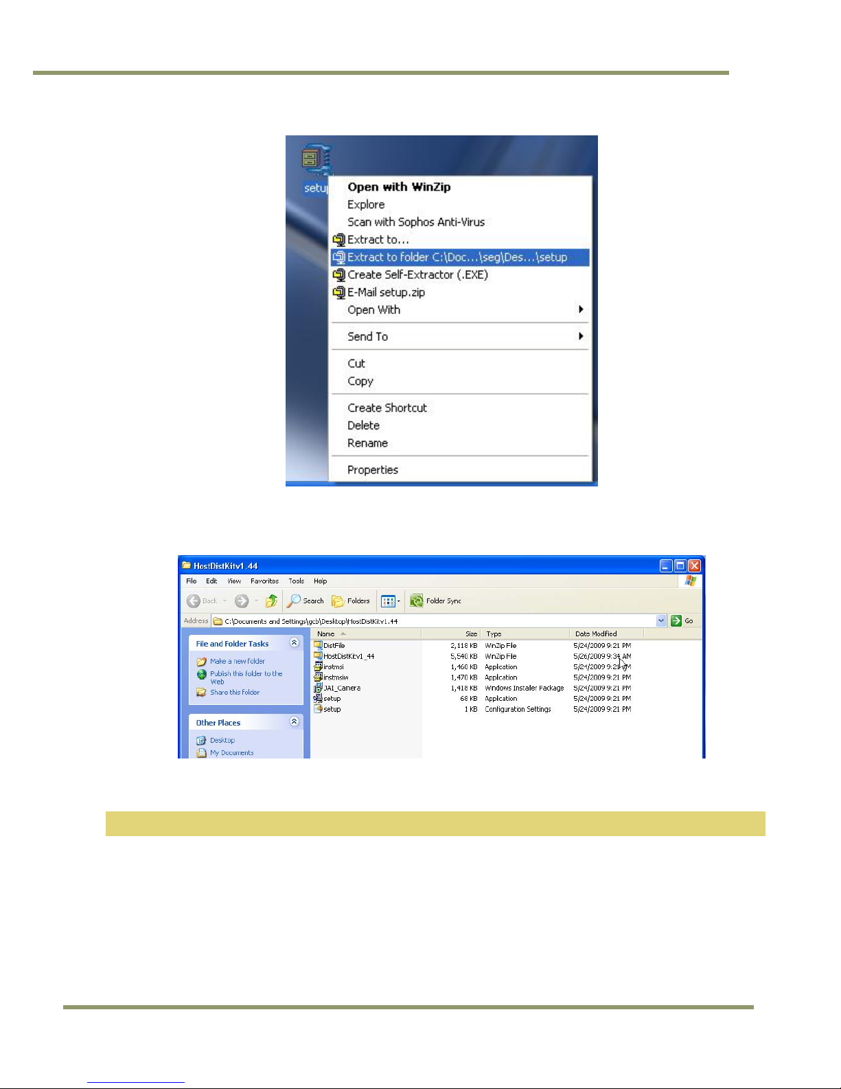
Figure 11. Right click to extract the compressed files. ..................................................................22
Figure 12. The extraction directory has the same name as the zip file. ..............................................22
Figure 13. Uninstall Existing TMC-775/TMC-773 Software ...............................................................23
Figure 14. Clean Install of TMC-775/TMC-773 Software..................................................................23
Figure 15. Accept the default install path. ................................................................................24
Figure 16. A bar indicates installation progress. ..........................................................................24
Figure 17. The installer asks to close. ......................................................................................24
Figure 18. A shortcut provides easy access to the TMC-775/TMC-773 software......................................25
Figure 19. Main Screen File Menu ............................................................................................25
Figure 20. Set the COM Port ..................................................................................................25
Figure 21. Load Settings Selections..........................................................................................26
Figure 22. Saving Settings.....................................................................................................26
Figure 23. Zoom Control Set ..................................................................................................28
Figure 24. Focus Control Set..................................................................................................28
Figure 25. Iris Control Set.....................................................................................................29
Figure 26. Shutter Control Set ...............................................................................................30
Figure 27. Firmware and Hardware Detail Boxes..........................................................................33
Figure 28. Video Pedestal .....................................................................................................33
Figure 29. Zoom Controls .....................................................................................................34
Figure 30. Focus Controls .....................................................................................................34
Figure 31. Iris Controls ........................................................................................................35
Figure 32. Color Correction Controls ........................................................................................35
Figure 33. ALC Controls Set...................................................................................................37
Figure 34. ALC Advanced Set .................................................................................................38
Figure 35. White Blemish Set .................................................................................................39
Figure 36. Physical Dimensions...............................................................................................43
Figure 37. Comparative Spectral Response for TMC-775 .................................................................44
Figure 38. Comparative Spectral Response for TMC-773 .................................................................44
Figure 39. Front End Assembly ...............................................................................................45
List of Figures ix
Page 10

TMC-775/TMC-773
List of Tables
Table 1 TMC-775/TMC-773 Product Specifications Table ............................................................ 42
x List of Tables
Page 11

TMC-775/TMC-77
3
TMC-775/TMC-773 Hardware Instructions
1 Hardware Introduction
1.1 Product description
The TMC-775/TMC-773 are designed to be simple, yet high quality color cameras capable of meeting a variety of
application requirements. Featuring an advanced HAD-type interline transfer CCD imager, these miniaturized high
resolution cameras offer many standard and optional features at a very affordable price. Except for optical format
(TMC-775 has a 1/2" optical format while the TMC-773 has a 1/3” optical format) the two cameras share a
common set of features. Both have an NTSC color video interface. Unless specifically noted, information in this
document regarding camera features and functions applies to both cameras.
1.2 Features
• Variable electronic shutter and random CCD integration.
The substrate drain-type shutter mechanism provides a superb picture at various speeds without smearing. The
electronic shutter rate can be externally adjusted, from 1/60 to 1/100,000 in discrete steps, by means of an
RS-232 communication port.
• Miniaturized and lightweight.
The use of a CCD image sensor in the video camera module and the development of special mini C-mount lenses
makes it possible to produce a very compact, lightweight and robust camera small enough to operate just like a
remote-head camera system without the back-end electronics.
• High sensitivity.
The TMC-775/TMC-773 cameras are two of the most low-light-sensitive CCD cameras available today. This
feature is especially important when using the faster shutter speeds. The cameras require only 0.25/0.45 lux
minimum illumination at maximum gain. In general, this allows use of a higher lens f-value while providing greater
depth of field and sharper images.
• Precise image geometry.
On the CCD image sensor, the photo sensor elements form exact rows both horizontally and vertically so that a
very precise image geometry may be obtained.
• Low lag/high resistance to image burning.
Since the CCDs are highly resistant to image burning, the cameras may be exposed to bright objects for a long
period of time. Because a “smear” phenomenon may occur when shooting a very bright object, an infrared cutoff
filter is recommended to obtain a clear picture.
• Integrated Lens Control
The TMC-775/TMC-773 cameras provide external signals which can be used to control motorized lenses.
Features such as Zoom, Focus, and Iris are controllable by means of the RS-232 communication port. The control
signals can support a variety of lenses. See the appendix for further details.
• Manual gain control and gamma adjustment
These adjustments, which are particularly important in vision system applications, are externally adjustable by
means of the RS-232 communication port
• Mirror Image (Horizontal)
The TMC-775/TMC-773 cameras provide the capability to horizontally mirror the image. This is externally
selectable by means of the RS-232 communication port.
• Genlock circuit.
A genlock circuit is built in to accept external sync for applications in which external sync is required.
Hardware Introduction 11
Page 12

• High resistance to magnetic field and vibration/mechanical shock.
Due to its ruggedized design, the CCD imager can withstand strong vibration and shock with little or no noise
appearing in the picture. Since the TMC-775/TMC-773 are not influenced by a magnetic field, they will produce
stable images even when placed next to objects such as electric furnaces, welding machines or NMR scanners.
• Quick start-up and low power consumption.
No more than 2 seconds are needed for the TMC-775/TMC-773 to warm up, and shooting can begin within a
second after turning on the camera. The power consumption is less than 2.5W. This makes the cameras excellent
for use with battery operated systems.
• Three Year Warranty
The CCD solid state image sensors allow the cameras to maintain a superior performance level indefinitely while
requiring virtually no maintenance. JAI, Inc. backs all of the TM Series cameras with a three-year warranty.
Warning:
Unscrewing the camera cover or opening the camera in any way will void this warranty.
1.3 Configurable Options Availability
• Automatic Level Control (ALC OP1-5)
• Blemish Compensation (OP2-5)
• Extended Temperature -40C - +65C (OP22-5-1)
• Conformal Coating (OP22-5-5)
TMC-775/TMC-773
1.4 Applications
The miniature size of the TMC-775/TMC-773 cameras eliminates the need for a remote-imager camera in all but
the most confined spaces. These cameras fit easily, both physically and functionally, into all types of machine
vision, automated inspection, and related applications. Other uses include remotely piloted vehicles, miniature
inspection devices, surveillance, microscopes and medical equipment.
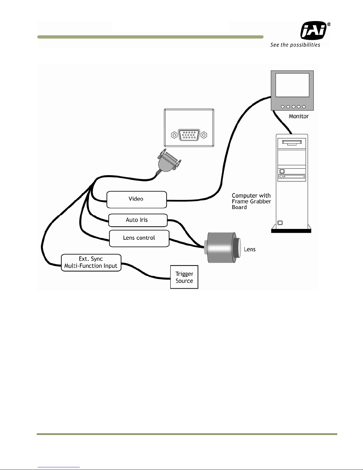
1.5 System Configuration
Figure 1 (next page) presents a typical system configuration in which a computer and frame grabber board are
used. A computer and frame grabber board are not required for operation of the TMC-775/TMC-773 cameras. The
RS-232 com port is not required for operation, but it is needed to configure the cameras and other control
functions.
12 Hardware Introduction
Page 13
TMC-775/TMC-77
3
Figure 1. TMC-775/TMC-773 System Configuration
Hardware Introduction 13
Page 14

2 Installation
The following instructions are provided to help you to set up your video camera system quickly and easily. It is
suggested that you read through these instructions prior to unpacking and setting up your camera system
2.1 Getting Started
2.1.1 Unpacking Instructions
It is recommended that the original packing cartons for the cameras and lenses be saved in case there is a need
to return or exchange an item. It is also recommended that any equipment being sent to another location for field
installation be bench tested to assure that everything is fully operational as a system.
2.1.2 Components List
Please begin by checking your order against the Components List (below) to assure that you have received
everything as ordered, and that nothing has been overlooked in the packing materials. If any item is missing,
please contact your JAI, Inc. representative immediately.
• TMC-775 or TMC-773 camera
• TMC-775/TMC-773 data sheet (Download from www.jai.com
• TMC-775/TMC-773 Operations Manual (Download from www.jai.com
• TMC-775/TMC-773 Camera Control Software (Download from www.jai.com
TMC-775/TMC-773
)
)
)
2.1.3 Accessories
Following is a list of additional accessories or equipment that may be recommended or required for your particular
application. Please check with your JAI, Inc. representative prior to the installation of your video system to
determine what you might need.
• Power Cable: 15P-02-9P-FULL or 15P-02-9P
• Power Supply: PD-12UU
• Tripod Mounting Kit: TP-50
(for dimensions go to: www.jai.com/EN/CameraSolutions/Products/Accessories/Pages/Home.aspx
2.2 Camera Setup
2.2.1 Connector Pin Configurations
2.2.1.1 15-Pin Connector
The TMC-775/TMC-773 have a 15-pin connector for power input. The pins handle a number of input and output
functions, which will be discussed further in other sections.
Figure 2. 15-Pin Connector
)
14 Hardware Installation
Page 15
TMC-775/TMC-77
3
2.2.2 Power Supply and Power Cable Setup
The TMC-775/TMC-773 cameras require a100-240V AC/12V DC 1.3A universal voltage power supply with a US
plug. The JAI cable for this series of cameras is part number is 15P-02-9P-FULL or 15P-02-9P, and the power
supply is PD-12UU.
2.2.2.1 JAI, Inc. Power Cables
If you are using JAI, Inc. power cables please refer to the pin-out diagram. The color coded leads use Grey for
Ground and Yellow for +12V DC.
Pin Description Pin Description Pin Description
1 +12V 6 +12V_Iris_Rtn 11 Auto Iris
2 Video Out 7 GND 12 Integrate
3 +12V_Iris 8 Lens Cont 3 13 Ext HD
4 Lens Cont 1 9 RX In 14 Ext VD/Composite
5 Lens Cont 2 10 GND 15 TX Out
Note: Make sure that the unused leads are not touching and that there is no possibility that the leads could
short due to exposed wires.
2.2.3 Attaching the Camera Lens
The TMC-775 camera accepts 1/2” or larger format size C-mount lenses, the TMC-773 camera accepts 1/3” or
larger format size C-mount lenses. To attach the C-mount lens to the camera, carefully engage the threads and
rotate the lens clockwise until it firmly seats on the mounting ring. Do not force the lens if it does not seat properly.
Please note that some lenses with extremely long flangebacks may exceed the mounting depth of the camera.
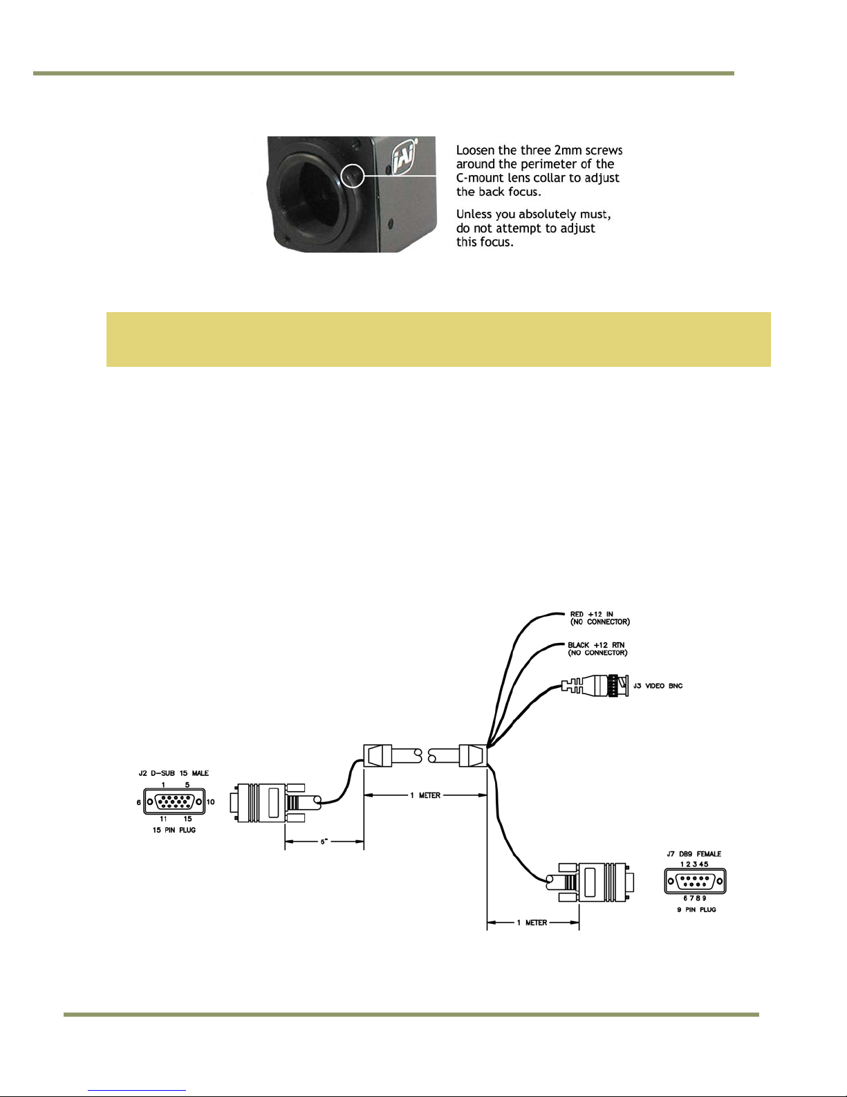
2.2.4 Adjustable Back-Focus
Before cameras are shipped, back focus is carefully set using a collimator, oscilloscope and other specialized
equipment. While the factory-set focus serves well in most cases, an adjustable back focus makes it possible to
improve image sharpness when using lower-cost zoom lenses, custom optics, or in unusual parameters.
There should be an obvious need to refocus the lens before attempting to change the back focus. This is an
exacting task. Some cameras have been returned to the factory to reset the back focus after failed attempts to
change the focus by customers. It is wise to label cameras whose back focus was adjusted.
1. The camera must be connected to a monitor before attempting to adjust the back focus.
2. To back focus the camera, first attach a C-mount lens in the mount. Be certain that the lens is properly
seated.
3. Next set the lens focus to infinity (if the lens has a manual iris, set the iris to a high f number while still
retaining a well illuminated image).
4. Loosen the three miniature hex set-screws (use a 0.9 mm hex wrench) that lock the focus ring in place.
Slowly turn the lens and focus ring assembly back and forth until you obtain the best image of the desired
object. This sets the back focus. Once the best image is obtained, tighten the focus ring set-screws until
they are snug. Do not over-tighten the screws.
Note: Mini-bayonet cameras adapted to C-mount do not have the back focus feature.
Hardware Installation 15
Page 16
TMC-775/TMC-773
Figure 3. Back Focus Set-Screw Locations
2.2.5 Auto-Iris Lens Setup
Auto-iris lenses with full video input can be used with the JAI, Inc. TMC-775 and TMC-773.
Note: Make sure that the power is removed from the camera before connecting or disconnecting the auto-iris
lens. There is a small chance that damage could occur to the auto-iris lens by plugging or unplugging it
while the camera is powered up.
Power down the camera before installing the auto-iris lens. To install the auto-iris lens in a JAI, Inc. camera, wire
the signal on the lens into the 1 V peak-to-peak video output (pin 11) on the camera. 12 volts DC is available on
pin 3.
Point the camera at a light area and then quickly towards a darker area. If everything is working properly, the iris
should adjust for the light change.
2.2.6 Monitor Display Mode
For monitoring real time video, connect the video output to an NTSC video monitor or other device.
2.2.7 Connectors and Cables
15-pin connector and cable: Standard cable is 15P-02-9P and 15P-02-9P-FULL.
Figure 4. 15P-02-9P Cable
16 Hardware Installation
Page 17
TMC-775/TMC-77
3
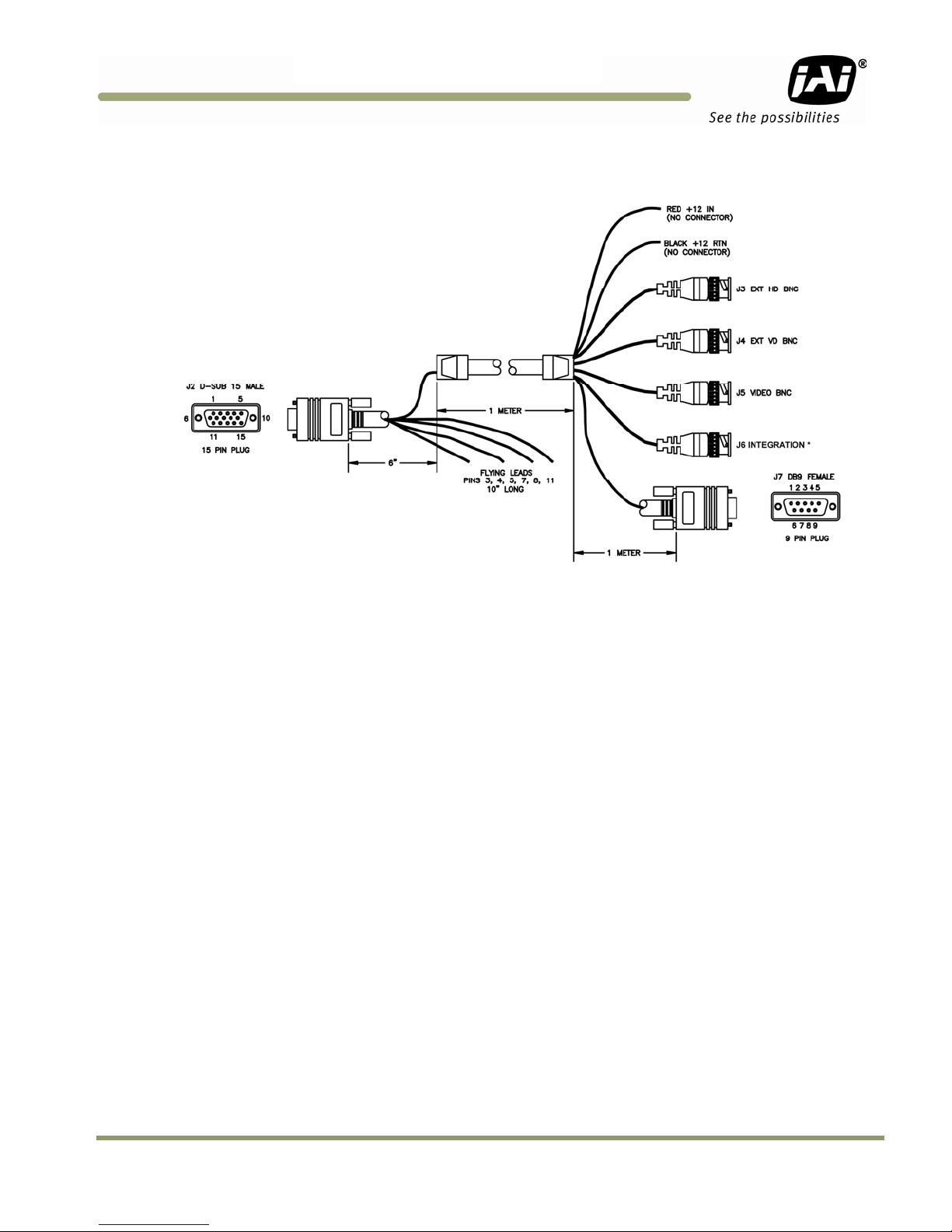
Figure 5. 15P-02-9P-FULL Cable
*On the TMC-775/TMC-773 this is for Integration function only. Does not support Ext. Trigger
Hardware Installation 17
Page 18
3 Functions and Operations
Apart from the standard continuous operation, the TMC-775/TMC-773 feature three external asynchronous trigger
modes (edge pre-select, pulse width controlled and Async RESET).
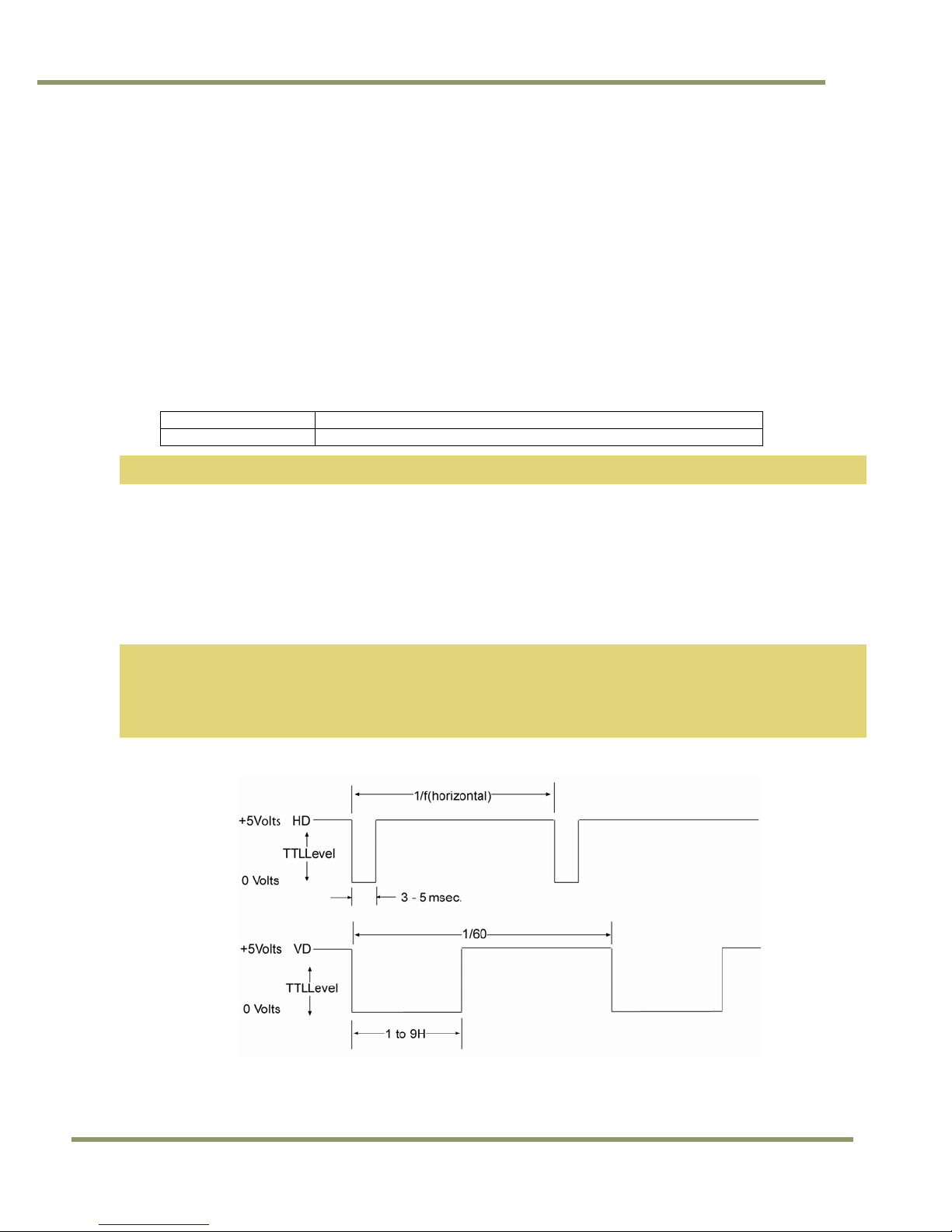
3.1 Input of Ext HD/VD Signals
In the default setting the camera will accept external HD/VD signals on pin 13 and 14 of the 15 pin connector. If
external HD/VD is applied, the camera will synchronize to it. If no external sync signals are applied, the camera
will operate with its internal x-tal controlled sync. The time requirements to the relation between VD and HD are
shown in Fig. 6.
To use this mode:
Input: Ext. VD in or int. VD out on pin 14 on 15 pin connector.
Ext. HD in or int. HD out on pin 13 on 15 pin connector.
Note: External sync system should follow the camera scanning system.
3.1.1 External Sync
The TMC-775/TMC-773 can accept external sync from an external sync generator or frame grabber. Input
specifications:
Internal/External auto switch
fH+15.734 KHz ± 5%, fV +59.95 Hz ± 5%
Min signal amplitude 3.5 Vp-p
TMC-775/TMC-773
Note: The TMC-775/TMC-773 have a one (1) horizontal line delay between the input VD signal and the output
video. If external vertical drive (VD) is applied to the camera, it may cause the video output to be
delayed 1 HD (1 H = ~64.0 µ s). If the imaging system is capable of automatically detecting the start of
video (within a few HD), then no problem will exist. Otherwise, reconfigure the video capturing
sequence to delay video acquisition of 1H.
Figure 6. Input Signals
18 Software Introduction & Installation
Page 19
TMC-775/TMC-77
3
3.2 Modes of Operation
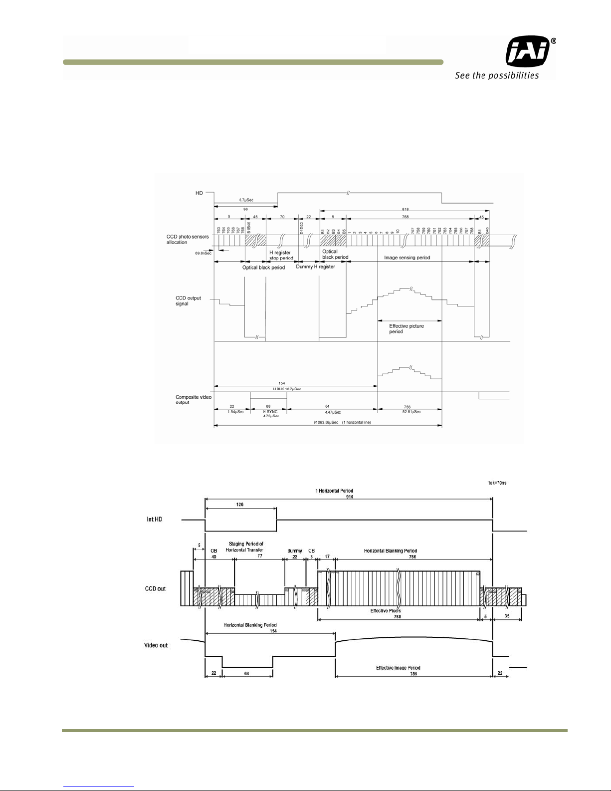
3.2.1 Continuous Operation (Non triggered)
For applications that do not require asynchronous external trigger (continuous operation). This is the factory
default setting of the camera.
Figure 7. Timing Chart
Figure 8. Horizontal timing details and pixel numbering for the CCD array. EIA
Function and Operations 19
Page 20
TMC-775/TMC-773
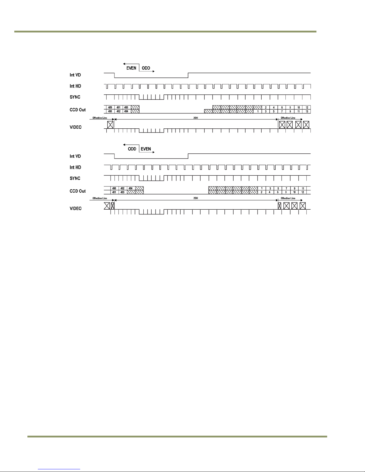
Figure 9. Vertical timing details for interlaced. NTSC
3.2.2 Integrate Mode
The standard factory setting for the TMC-775/TMC-773 camera is FIELD MODE.
An External Integrate mode is located on pin 12 of the 15 pin connector. This allows frames to continually
integrate until this input pin is released. This is normally high or open. Holding the input “low” starts the integration.
To use this mode:
Input: Ext. signal to pin 12 on 15 pin connector.
Set MFI mode: “VD mode”
Set MFI Termination: “Hi Z”
3.2.3 Vertical Mode
The standard factory setting for the TMC-775/TMC-773 camera is FIELD MODE.
In Field Mode, two horizontal rows are scanned together, changing the pair at each interlace scan.
3.2.4 External Trig
The External Trig functions are not supported during continuous operation.
20 Software Introduction & Installation
Page 21
TMC-775/TMC-77
3
TMC-775/TMC-773 Camera Control Software
4 Software Introduction
The TMC-775/TMC-773 are supported by a software control tool that opens the RS-232 serial port (COM). This
document addresses the JAI TMC-775/TMC-773 camera software available for download at www.jai.com.
4.1 Software Installation
Following are instructions to install the TMC-775/TMC-773 camera software on a PC.
4.1.1 Before Installing the Camera-Control Software
Before installing the camera control software, please note the following.
• The TMC-775/TMC-773 camera control software is tested for Microsoft Windows 2000 and XP operating
systems.
• We recommend that you use small fonts for the Display Properties dialog box in the control panel.
• The TMC-775/TMC-773 camera control software requires one free communication port that is not in
conflict with other peripherals such as the mouse or modem.
4.1.2 Installing the Software
To install the TMC-775/TMC-773 camera control software, follow the steps below.
1. Download the TMC-775/TMC-773 software from the JAI, Inc. web site at www.jai.com.
2. Locate the software by going to the camera description (TMC-775 or TMC-773) and clicking on the
Software link, or by searching using the site search feature.
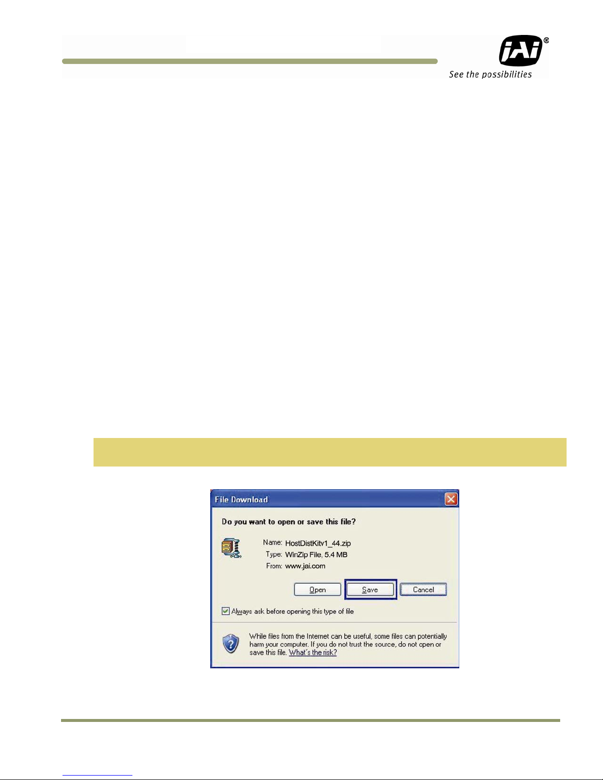
3. Click on the “Save” button to save a compressed copy of the software to the hard drive of your system.
Note: If you go to software and download based on the camera description, for example, TMC-775, the
software download is the correct, and latest released version.
Figure 10. Use Save to download a copy of the software.
The software is compressed, use decompression software to create the installation directory.
Software Introduction & Installation21
Page 22
TMC-775/TMC-773
Figure 11. Right click to extract the compressed files.
By choosing to “Extract to folder...” (C: normally indicates the hard drive that includes the desktop) the directory is
in the same place as the download, and can be easily moved to any desired location.
Figure 12. The extraction directory has the same name as the zip file.
3.Open the directory and double-click on setup to begin the TMC-775/TMC-773 software install.
4.Follow the installation instructions.
Note: You can change the installation directory if you want.
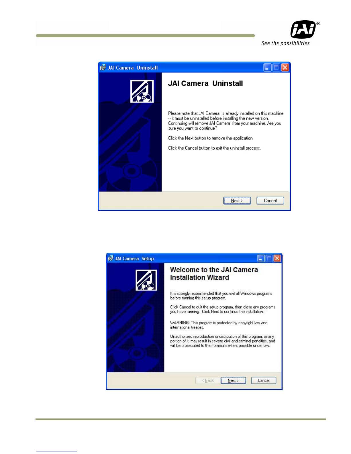
4.1.2.1 Uninstalling Previous TMC-775/TMC-773 JAI, Inc. Software
• If you already have TMC-775/TMC-773 software on the hard drive, the installer asks to uninstall the
software.
• Accepting the uninstall allows the existing software to be removed. The installer then closes.
• To initiate a new installation it is necessary to click “Setup” again.
22 Software Introduction & Installation
Page 23
TMC-775/TMC-77
3
Figure 13. Uninstall Existing TMC-775/TMC-773 Software
4.1.3 Fresh Installation of the TMC-775/TMC-773 Software
• Start by clicking on the Setup icon in the software folder.
• Click Next to begin a clean install.
Figure 14. Clean Install of TMC-775/TMC-773 Software
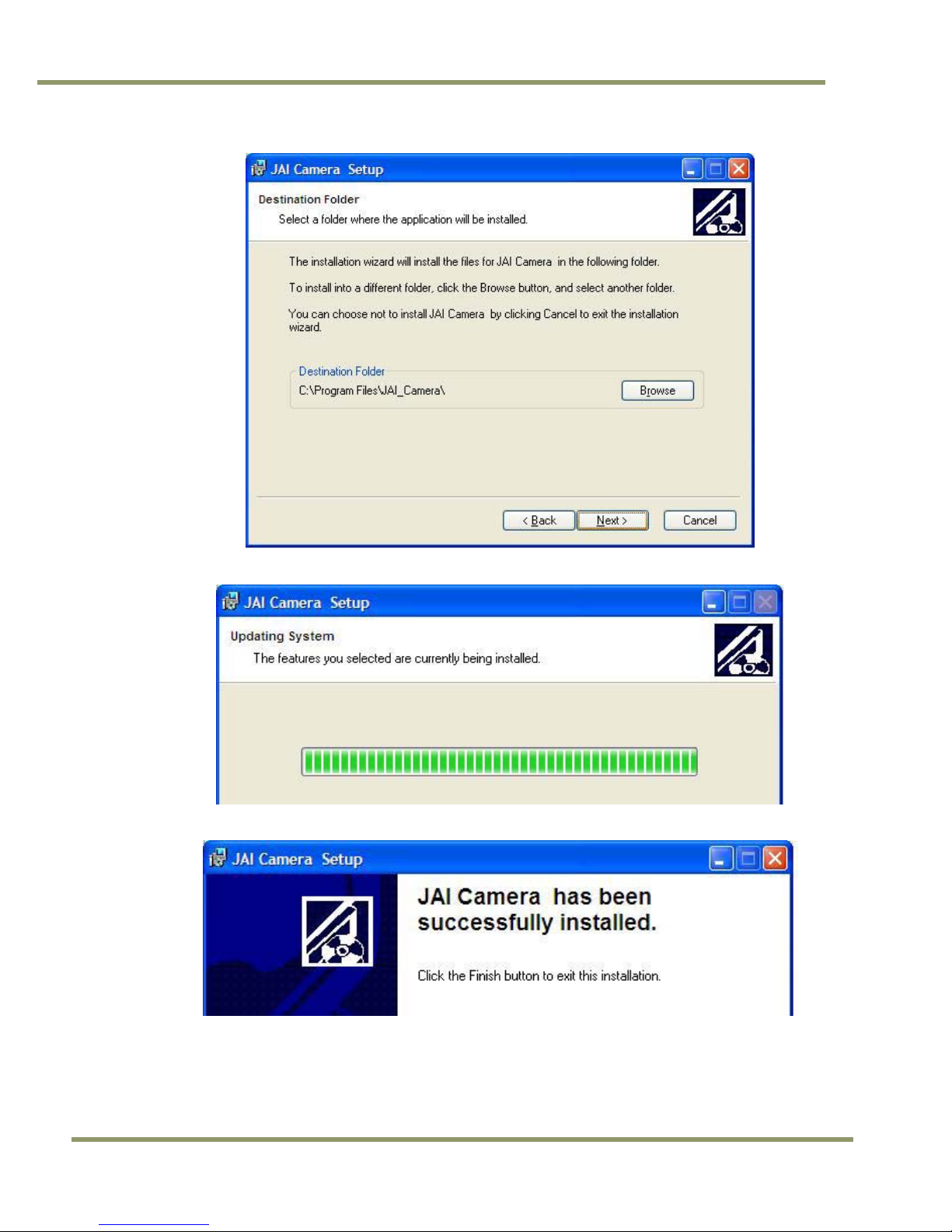
• Accept the default installation path by clicking Next, if there is room on the hard drive. Use the browse
button if you wish to set a different installation path.
• Click the Next button twice to begin the actual software installation.
Software Introduction & Installation23
Page 24
TMC-775/TMC-773
Figure 15. Accept the default install path.
Figure 16. A bar indicates installation progress.
Figure 17. The installer asks to close.
• It is not necessary to restart the computer after installing the TMC-775/TMC-773 software.
• Click on the Windows Start menu to access a shortcut to the TMC-775/TMC-773 software.
• Click on the JAI_TMC-775/TMC-773 icon to start the software.
24 Software Introduction & Installation
Page 25
TMC-775/TMC-77
3
Figure 18. A shortcut provides easy access to the TMC-775/TMC-773 software.
4.2 Using the TMC-775/TMC-773 Software
You must connect a camera via an RS-232 cable to the computer and power it up before starting the camera
control software.
Start the TMC-775/TMC-773 software by clicking on the Start menu, and then selecting JAI_TMC-775/TMC-773
and clicking the JAI TMC-775/TMC-773 shortcut on the right (Figure 18).
4.2.1 The Main Screen
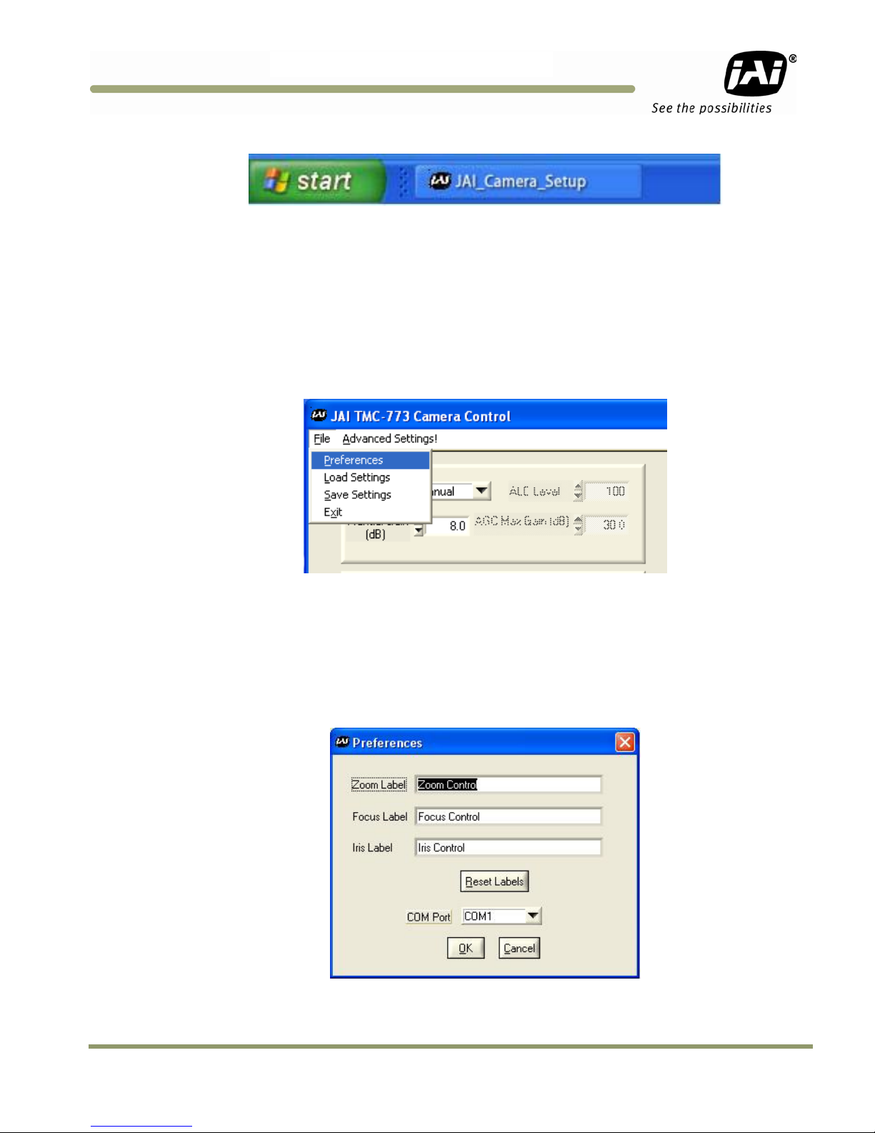
The main screen offers several menus. Click on File in the menu bar to access the following:
Figure 19. Main Screen File Menu
4.2.1.1 Preferences
Selecting Preferences opens a separate window that allows the user to set the COM port the camera will use to
interface with the computer. Set the port number by selecting it in the COM Port drop down list box. The system
defaults to the COM port number where the camera is attached.
In addition, this window allows you to rename the Control functions of "Zoom", "Focus", and "Iris". Thus, the
controls can be used for more general purpose functions, such as stepper motors for "Pan" and "Tilt".
Figure 20. Set the COM Port
Software Introduction & Installation25
Page 26

TMC-775/TMC-773
4.2.1.2 Load Settings
Selecting Load Settings causes the camera to open a separate window that allows the user to select the camera
settings they will use to interface with the computer. The factory defaults are saved in the camera. Users can
access UserSet1 and UserSet2 once settings have been saved into the camera.
Figure 21. Load Settings Selections
4.2.1.3 Save Settings
Selecting Save Settings causes the camera to open a separate window that allows the user to save their currently
configured camera settings. As a user you can create UserSet1 and UserSet2 by selecting the appropriate line of
the drop down menu. Factory Defaults can not be overwritten.
Figure 22. Saving Settings
4.2.1.4 Exit
Selecting Exit closes the JAI TMC-775/TMC-773 Camera Control program.
26 Software Introduction & Installation
Page 27

TMC-775/TMC-77
3
4.3 Camera Control Main Window
The camera is configured using the main window.
The main window has these controls from left to right:
• ALC Mode (top left)
− ALC/AGC (if enabled)
− Manual Gain
• Zoom Control (top right)
− Zoom In Coarse
− Zoom In Fine
− Zoom Out Coarse
− Zoom Out Fine
• Focus Control (middle right)
− Focus In Coarse
− Focus In Fine
− Focus Out Coarse
− Focus Out Fine
• Iris Control (lower middle right)
− Iris Open Coarse
− Iris Open Fine
− Iris Closed Coarse
− Iris Closed Fine
• Gamma/Shutter
− Gamma
− Shutter Speed
• MFI/Trigger
− MFI Input
− MFI Termination
• Image Pre-processing functions
− Blemish compensation
− Mirror Imaging (horizontal)
− Color Control Sliders
• White Balance (bottom right)
− AWB mode
− AWB enable
Software Introduction & Installation27
Page 28

TMC-775/TMC-773
4.3.1 Manual Gain
In manual mode, the Manual Gain setting and Shutter Speed control may be adjusted to get the desired exposure.
• Manual Gain
The Manual Gain allows you to set the system gain. The range is from 0dB to 30dB (3dB to 30dB for TMC-773).
4.3.2 Zoom Control
The zoom control allows you to remotely focus the camera lens on a motorized zoom lens when properly wired to
the 15-pin connector.
Figure 23. Zoom Control Set
• Zoom In Coarse
Pressing and holding this button causes the lens to “zoom in” in a rapid fashion. Releasing the button causes the
zoom to stop. The speed of the zoom may be set using the Advanced Setting Menu (see section 4.5)
• Zoom In Fine
Pressing and holding this button causes the lens to “zoom in” in a slow fashion. Releasing the button causes the
zoom to stop. The speed of the zoom may be set using the Advanced Setting Menu (see section 4.5)
• Zoom Out Coarse
Pressing and holding this button causes the lens to “zoom out” in a rapid fashion. Releasing the button causes the
zoom to stop. The speed of the zoom may be set using the Advanced Setting Menu (see section 4.5)
• Zoom Out Fine
Pressing and holding this button causes the lens to “zoom out” in a slow fashion. Releasing the button causes the
zoom to stop. The speed of the zoom may be set using the Advanced Setting Menu (see section 4.5)
Note: This capability requires a lens with a motorized zoom control.
4.3.3 Focus Control
The focus control allows you to remotely focus the camera lens when properly wired to the 15-pin connector.
Figure 24. Focus Control Set
• Focus In Coarse
Pressing and holding this button causes the lens to “focus in” in a rapid fashion. Releasing the button causes the
focus to stop. The speed of the focus may be set using the Advanced Setting Menu (see section 4.5)
28 Software Introduction & Installation
Page 29

TMC-775/TMC-77
3
• Focus In Fine
Pressing and holding this button causes the lens to “focus in” in a slow fashion. Releasing the button causes the
focus to stop. The speed of the focus may be set using the Advanced Setting Menu (see section 4.5)
• Focus Out Coarse
Pressing and holding this button causes the lens to “focus out” in a rapid fashion. Releasing the button causes the
focus to stop. The speed of the focus may be set using the Advanced Setting Menu (see section 4.5)
• Focus Out Fine
Pressing and holding this button causes the lens to “focus out” in a slow fashion. Releasing the button causes the
focus to stop. The speed of the focus may be set using the Advanced Setting Menu (see section 4.5)
Note: This capability requires a lens with a motorized focus control.
4.3.4 Iris Control
The iris control allows you to remotely change the aperture of the lens when properly wired to the 15-pin
connector.
Figure 25. Iris Control Set
• Iris Open Coarse
Pressing and holding this button causes the iris to open in a rapid fashion. Releasing the button causes the iris to
stop. The speed of the iris control may be set using the Advanced Setting Menu (see section 4.5)
• Iris Open Fine
Pressing and holding this button causes the iris to open in a slow fashion. Releasing the button causes the iris to
stop. The speed of the iris control may be set using the Advanced Setting Menu (see section 4.5)
• Iris Close Coarse
Pressing and holding this button causes the iris to close in a rapid fashion. Releasing the button causes the iris to
stop. The speed of the iris control may be set using the Advanced Setting Menu (see section 4.5)
• Iris Close Fine
Pressing and holding this button causes the iris to close in a slow fashion. Releasing the button causes the iris to
stop. The speed of the iris control may be set using the Advanced Setting Menu (see section 4.5)
Note: This capability requires a lens with a motorized iris control.
Software Introduction & Installation29
Page 30

TMC-775/TMC-773
4.3.5 Shutter
Figure 26. Shutter Control Set
• Shutter Speed
The TMC-77X can be set for a range of shutter speeds by selecting the desired speed from the drop down list
box. The speed is adjustable in increments of one horizontal line time (~63.56 us), from 1 to 260 lines.
4.3.6 Gamma (Factory default setting = 1.0)
Gamma adjustment affects the linearity of the video signal with respect to the incoming light. The software offers
two gamma options, 1.0 and 0.45. The 1.0 setting captures an image while maintaining a linear relationship
between incoming light and output video level. The 0.45 setting creates a nonlinear relationship that corrects for
the nonlinear manner in which most video monitors display an image. The 0.45 setting is typically used when an
image will be viewed on a video monitor. The 1.0 setting is typically used when the image will be captured by a
frame grabber and undergo subsequent image processing.
4.3.7 MFI Input (Multi-Function Input)
One of the inputs available on the rear panel DB15 connector serves multiple functions. The MFI Input selection
allows the operator to choose the one that best serves the application.
VD Input is used for genlocking to a vertical drive input
CSYNC is used for genlocking to a composite sync input
• MFI Termination
This option allows the option of terminating the MFI in either 75 ohms, or a high impedance.
− HiZ setting terminates in a high impedance.
− 75 ohm terminates in 75 ohms.
4.3.8 Mirror Image
This feature allows the user to flip the image horizontally (mirror image). “Off” corresponds to a normal image and
“On” mirrors the image.
4.3.9 Color Sliders
This feature allows the user to fine tune the color fidelity with four sliders controlling Y-gain, U-Saturation, Vsaturation, and Hue.
30 Software Introduction & Installation
Page 31

TMC-775/TMC-77
3
4.3.10 White Balance
This area allows the user to set the white balance level.
White Balance Mode allows the user to select between “Automatic” and “Manual”.
Automatic - When this is selected, the camera continuously adjusts the white balance as the scene changes.
Manual - When this is selected, the camera will only adjust the white balance when the AWB button is clicked.
AWB button - AWB stands for Automatic White Balance. When this button is clicked, the camera will adjust its
white balance according to the current scene. For a better white balance adjustment, point the camera at a
“white” image area and click on the AWB button. Make sure the image is no more than 80% saturated, otherwise
the white balance will not be correct. Additional color adjustments can be done using the color sliders and/or the
color matrix in the Advanced Settings window (section 4.5.6).
Software Introduction & Installation31
Page 32

4.4 Advanced Settings Window
This window is accessed from the menu at the top of the Camera Control Main Window.
TMC-775/TMC-773
32 Software Introduction & Installation
Page 33

TMC-775/TMC-77
3
4.5 Advanced Setting details
4.5.1 Software/Hardware Details
Figure 27. Firmware and Hardware Detail Boxes
• Customer ID, Unit ID, Date Code, Unit Rev.
During factory setup, these fields will be populated with the factory unit information.
Customer ID can be updated by the customer should they wish to maintain their own unique ID information.
Unit ID, Date Code, and Unit Rev are for JAI internal use only.
• Host Control Ver.
The host software version is displayed.
• Camera Model
The JAI camera model number is displayed.
• Firmware Ver.
The camera firmware version is displayed.
• FPGA Ver.
The camera FPGA version is displayed
4.5.2 Video
Figure 28. Video Pedestal
• Video Pedestal
The Video Pedestal sets the video pedestal level for the black level reference for the video output.
• Video White Clip
The Video White Clip sets the maximum video level for the white clip reference for the video output.
Software Introduction & Installation33
Page 34

TMC-775/TMC-773
4.5.3 Advanced Zoom Controls
Figure 29. Zoom Controls
• Zoom Max Voltage
This sets the maximum voltage that will be applied to the zoom motor. The range is 0V to 9V.
• Zoom Coarse Step
This sets the voltage that gets applied to the zoom motor when the coarse Zoom control is activated. It is specified
as a percentage of the Zoom Maximum Voltage
• Zoom Fine Step
This sets the voltage that gets applied to the zoom motor when the fine Zoom control is activated. It is specified as
a percentage of the Zoom Maximum Voltage
4.5.4 Advanced Focus Controls
Figure 30. Focus Controls
• Focus Max Voltage
This sets the maximum voltage that will be applied to the focus motor. The range is 0V to 9V.
• Focus Coarse Step
This sets the voltage that gets applied to the focus motor when the coarse Focus control is activated. It is
specified as a percentage of the Focus Maximum Voltage
• Focus Fine Step
This sets the voltage that gets applied to the focus motor when the fine Focus control is activated. It is specified
as a percentage of the Focus Maximum Voltage
34 Software Introduction & Installation
Page 35

TMC-775/TMC-77
3
4.5.5 Advanced Iris Controls
Figure 31. Iris Controls
• Iris Max Voltage
This sets the maximum voltage that will be applied to the iris motor. The range is 0V to 9V.
• Iris Coarse Step
This sets the voltage that gets applied to the iris motor when the coarse Iris control is activated. It is specified as a
percentage of the Iris Maximum Voltage
• Iris Fine Step
This sets the voltage that gets applied to the iris motor when the fine Iris control is activated. It is specified as a
percentage of the Iris Maximum Voltage
4.5.6 Color Matrix
Figure 32. Color Correction Controls
4.5.6.1 Color Correction Coefficients
This matrix allows even more color adjustment by allowing the user to adjust the mix of the red, green, and blue
within each pixel. This is an advanced feature and should not be used unless the user is very familiar with the
color space environment. Please consult factory if adjustments are required.
Software Introduction & Installation35
Page 36

4.6 Color Processing Window
This window is accessed from the menu at the top of the Camera Control Main Window.
TMC-775/TMC-773
4.6.1.1 Sharpening
This selection box allows the user to select the level of sharpness in the image, where the higher gain level
adjustment correlates to higher edge sharpening. There are two selectable modes for sharpening: Standard and
Enhanced.
4.6.1.2 Color Saturation
This selection box allows even more color adjustment by allowing the user to adjust the saturation levels of both
Cr and Cb. The higher the gain gives a higher color saturation level
36 Software Introduction & Installation
Page 37

TMC-775/TMC-77
3
5 Configurable Options Available
This section describes the additional options the TMC-775/TMC-773 offers. These options are only applicable if
the units have been ordered with theses options.
Figure 33. ALC Controls Set
5.1.1 ALC (Option OP1-5)
This optional feature provides an automatic level control (ALC) function for the camera. The ALC function
combines both automatic gain and exposure control to give the best response to lighting conditions. The function
also allows selectable modes which provide more flexibility in determining the best scene performance. If
configured with this option, it is enabled in gain section of the camera control main window. In automatic mode,
the camera varies its internal gain and shutter speed dynamically to get a consistent exposure based on the
setting of the other ALC parameters. In manual mode, the Manual Gain setting and Shutter Speed control may be
adjusted to get the desired exposure.
• Manual Gain
The Manual Gain allows you to set the system gain. The range is from 5dB to 32dB. The Manual Gain control is
only operative when the ALC Mode is set to Manual.
• ALC Level
The ALC Level setting determines the desired exposure level when the ALC Mode is set to Automatic. The units
are arbitrary and vary from 0 to 255. A higher Level setting will result in a brighter image.
• ALC Max Gain
The ALC Max Gain setting specifies the maximum system gain that will be applied when ALC Mode is set to
Automatic.
• ALC Mode
In Automatic Mode the system will automatically adjust the gain and shutter speed (if selected – see below) to
maintain a consistent exposure level. In Manual Mode the user may adjust the Manual Gain and Shutter Speed
settings to obtain the desired exposure level.
5.1.2 Advanced Settings for ALC
In the “Advanced Settings” page, there are additional features which allow to user to customize the ALC
functionality to suit their specific image scenes. Once this is selected, the “Main” page will use these settings
when adjusting the video level.
Functional Options 37
Page 38

TMC-775/TMC-773
Figure 34. ALC Advanced Set
• ALC Window
These parameters define the rectangular Region of Interest (ROI) that will be used to calculate the ALC exposure
level. The user defines the upper left and bottom right corner of the ROI using X & Y coordinates. The ROI can
target the center of the image, or can be set to avoid a certain portion of the image so that its light value will not
affect the ALC function. A window display can be turned on to help the user identify his ROI, but it should be
always set to off during normal operation. The normal default of the ALC window is 90% of the full frame image.
• ALC Mode
This allows the user to select the type of algorithm for the ALC function.
Average: The ALC level is based on the calculated average value of the selected window.
• Bright Speed
This selection sets a time value to wait a pre-selected time before the ALC will adjust when the scene is changing
from dark-to-bright. For example, if the average scene level is 50 and it immediately changes to 100, the camera
will verify that the scene has stayed at 100 for the pre-selected time before it will adjust the ALC.
• Dark Speed
This selection sets a time value to wait a pre-selected time before the ALC will adjust when the scene is changing
from bright-to-dark. For example, if the average scene level is 100 and it immediately changes to 50, the camera
will verify that the scene has stayed at 50 for the pre-selected time before it will adjust the ALC.
• Impulse Filter
This selection sets a time value to wait a pre-selected time before the ALC will adjust when the scene is changing.
It acts like a hysteresis loop for the system.
• Electronic Shutter
Setting the ALC Mode to “automatic” in the main control window causes the camera to begin working to maintain
the proper exposure, based on the settings in the ALC Level and AGC Max Gain boxes. When the Electronic
Shutter box is also checked, the Automatic Exposure Control (AEC) function of the ALC mode is enabled, causing
the electronic shutter to work together with auto gain to achieve the optimum ALC level. If this box is unchecked,
only auto gain is used, which may be insufficient to achieve the desired ALC level. This configuration (ALC on,
Electronic Shutter off) is normally used only when an auto-iris lens is connected to the camera. This allows auto
gain and auto iris to control the exposure, while eliminating the chance of any conflicts between the auto shutter
and auto iris actions.
5.1.3 White Blemish Compensation (Option OP2-5)
This optional feature allows the user to enable or disable white blemish compensation. The camera can come precalibrated with the white blemishes mapped and saved into the flash memory. Once calibrated, the camera will
then interpolate and substitute for the white pixels.
38 Functional Options
Page 39

TMC-775/TMC-77
3
Figure 35. White Blemish Set
5.1.3.1 Blemish Threshold (%)
This feature is used to detect the white blemish pixels. The user enters the percentage above the mean to
determine the blemishes. Clicking on “Locate Blemishes” will display the number of blemishes found in the
“Blemish Count” box. If no blemishes are detected, the user can lower the threshold until it starts to detect them.
NOTE: The total number of blemishes allowed is 64. Thus, if there are more than 64, the camera will only
correct the first 64 blemishes it detects. To reduce the number of blemishes, the user should raise the
threshold.
Once the blemishes are located, the “White Blemish Compensation” can be enabled or disabled in the main
control window. The file should be saved under the “User Set.”
5.1.4 Extended Temperature Range (-45°C to +65°C) (Option OP22-5-1)
This optional feature assures that the camera will operate at this extended temperature range. If this option is
selected, each unit is individually tested, validated and temperature cycled through the temperature range.
Although the unit is guaranteed to operate throughout the temperature range, there may be some reduced
performance, such as higher noise, reduced SNR, etc.
5.1.5 Conformal Coat (Option OP22-5-5)
This optional feature calls for the individual printed circuit boards to be individually conformal coated. Conformal
coating protects the camera from harsh environments, such as areas of high humidity, salt and spray conditions,
etc. The conformal coating is normally a urethane based acrylic, but other materials can be used based on the
customer’s request.
Functional Options 39
Page 40

6 Troubleshooting
6.1 Problems and Solutions
Following are troubleshooting tips for common problems. Generally, problems can easily be solved by following
these instructions. If the following remedies fail to offer a solution to your problems, please contact a JAI, Inc.
representative.
6.1.1 Symptom: No Video
Remedies: Check that the following are properly connected and operational. • Power supplies
• Power supplies
• Power cables
• Main power source
• Shutter control
• Async mode
• Lens
TMC-775/TMC-773
6.1.2 Symptom: Dark Video
Remedies: Check that the following are properly connected and operational.
• Shutter selection
• Iris opening on the lens
6.1.3 Symptom: Non-synchronized Video
Remedies: Check that the following are properly connected and operational.
• Proper mode output
• Frame grabber software camera selection
6.2 TMC-775/TMC-773 Camera Control Software Troubleshooting
6.2.1 Problem: Camera is not recognized
After adjusting some software settings, and closing the program, the TMC-775/TMC-773 software will not
recognize the camera when attempting to open it at a later time.
6.2.2 Solution:
• Close and reopen the program.
• Uninstall and reinstall the TMC-775/TMC-773 software.
6.2.3 Problem: Camera communication not found
When the camera is first turned on, the port communication is not found.
40 Troublehsooting
Page 41

TMC-775/TMC-77
3
6.2.4 Possible Solutions:
• RS-232 connection is not correct or plugged in.
• Wrong communication port is selected
• First, find out which port has been selected by going to the Device Manager to determine the COM port.
• Next, Open JAI Camera Control tool, select Preferences, and select the COM port. If working properly
the camera should now be connected.
6.2.5 Problem: Program Controls are Grayed Out
After opening the program, all boxes are grayed out.
6.2.6 Solution:
The connection to the camera is not correct. Check the cable and all other connections.
6.3 Information and Support Resources
For further information and support:
North American Technical Support
Phone : 408-383-0300
Email: camerasupport.americas@jai.com
European Technical Support
Phone: +45 4457 8950
Email: camerasupport@jai.com
Japan/Asia Technical Support
Phone: +81 45 440 0154
Email: camerasupport@jai.com
Mailing Address
JAI, Inc.
Sales Department
625 River Oaks Parkway
San Jose, CA 95134
ATTN: Video Applications
Web site: www.jai.com
Troubleshooting 41
Page 42

7 Specifications
7.1 Product Specifications
Table 1
Model TMC-775 (EIA) TMC-773 (EIA)
Sensor
Active pixels 768 (H) x 494(V)
Cell size 8.4 µm x 9.8 µm 6.35 µm x 7.4 µm
Scanning 525 lines / 60 Hz
Synchronization
TV resolution 570 (H) x 350 (V)
S/N ratio >50 dB min. (AGC off)
Sensitivity
Video output 1.0 Vp-p composite video, 75 Ω
ALC OP1-5 ON/OFF, (RS-232 controlled)
Gamma
Lens mount C-mount (adjustable)
Power requirement 12V DC, 175 mA typical at 25° C
Operating temperature
Standard
OP22-5-1
Vibration 7Grms (20 Hz to 2000 Hz) Random
Shock 70 G, 11 ms, half-sine
Dimensions (H x W x L)
Weight
Power supply PD-12UU Flying leads
Cables 15P-02-9P-Full or 15P-02-9P
Optional functions
TMC-775/TMC-773 Product Specifications Table
TMC-775/TMC-773
1/2” NIR
interlace CCD
IXC428AK
Internal/External auto switch
HD/VD 4.0 Vp-p impedance 10 K Ω
VD = interlace/non-interlace
HD = 15.73 KHz ± 50 ppm
0.25 lux (f=1.4)
max gain 50% video
0.45 / 1.0 (RS-232 controlled)
1.0 Factory Default
-10° C to +50° C
-40° C to +65° C (reduced performance may occur)
32 x 42 x 48.48 mm with mechanical enclosure
29.3 x 39.4 x 35.66 mm without mechanical enclosure
113 g with mechanical enclosure
69.9 g without mechanical enclosure
OP1-5 - Auto level control (EE and AGC),
OP2-5 - Blemish compensation, OP3-2 - Optical filter removed,
OP22-5-1 – Extended temperature, OP22-5-5 – Conformal coat
1/3” NIR
interlace CCD
IXC258AK
0.45 lux (f=1.4)
max gain 50% video
42 Specifications
Page 43

TMC-775/TMC-77
3
7.1.1 Physical Dimensions
Figure 36. Physical Dimensions
Caution: When mounting the camera to any fixture, do not use screws that extend more than 5 mm into the
camera housing to avoid possible damage to the internal circuitry. For attaching the tripod mounting
plate, only the supplied screws should be used.
Specifications 43
Page 44

TMC-775/TMC-773
Figure 37. Comparative Spectral Response for TMC-775
Figure 38. Comparative Spectral Response for TMC-773
44 Specifications
Page 45

TMC-775/TMC-77
3
8 Appendix
8.1 Front End Detail
Figure 39. Front End Assembly
8.2 Camera Command Overview
The TMC-775 and TMC-773 cameras can be controlled via RS-232 communications. Commands are sent to the
camera as a string of ASCII characters. Each command begins with a start character of “:” and ends with the end
character CR (Decimal 10, hex D) which is indicated as <cr> in the table below. The camera will acknowledge
successful receipt and processing of the command with the response specified in the table below. If, for any
reason, the camera cannot recognize or process a command, it will respond with the Nack response “:e”<cr>.
The camera will generate output only in response to an input command. Commands are not buffered. A new
command should not be sent until the camera has responded to the previous command. Any input to the camera
will be ignored until processing of the current command has completed and the camera response has been
output. Similarly, all characters received after the end character <cr>, but before the receipt of the start character
“:” will be ignored.
NOTE: The List of Camera Commands is fully comprehensive which includes commands for not only the TMC-
775/TMC-773 series cameras, but also the TM-70X series, the TM-77X series, and the AG-7000 cameras.
Thus, not all the commands listed are valid for TMC-775/TMC-773 series cameras.
Appendix 45
Page 46

8.3 Detail List of Camera Commands
Alphabetical Table of Camera Commands
Commands marked with “*” are in-house commands.
Command String Function
AEC? AEC Mode
AEC= AEC Mode
AFA? AFE Register Address
AFA= AFE Register Address
AFW= AFE Write
AGN? AGC Manual Gain
AGN= AGC Manual Gain
ALV? AGC Level
ALV= AGC Level
ALM? ALC Mode
ALM= ALC Mode
AMD? AGC Mode
AMD= AGC Mode
AMX? AGC Max
AMX= AGC Max
AWB? AWB State
AWB= AWB State
AWW? AWB Window Display
AWW= AWB Window Display
BBL? Color Balance – Blue
BBL= Color Balance – Blue
BIN= Binning for ALC
BIN? Binning for ALC
BRT? Current Brightness
BCT? Blemish Count
BTH? Blemish Threshold
BTH= Blemish Threshold
BTS? Bright Speed
BTS= Bright Speed
CAM? Camera Model
CAM=* Camera Model Number
CDx? CD1,2,3,4 Column Defect Address
CDx= CD1,2,3,4 Column Defect Address
CDI? Defect Indicator
CDI= Defect Indicator
CFA? Chroma Filtering State - CFA
CFA= Chroma Filtering State - CFA
CFG? Chroma Filtering Gain - CFG
CFG= Chroma Filtering Gain - CFG
CFT? Chroma Filtering Threshold - CFT
CFT= Chroma Filtering Threshold - CFT
CGB? Color Gain - Blue
CGB= Color Gain - Blue
CGG? Color Gain - Green
CGG= Color Gain - Green
CGR? Color Gain - Red
CGR= Color Gain - Red
CIB? Color Intensity - Blue
CIG? Color Intensity - Green
CID? CID Customer ID String
TMC-775/TMC-773
46 Appendix
Page 47

TMC-775/TMC-77
3
Command String Function
CID= CID Customer ID String
CIR? Color Intensity - Red
CMD? Color Mode
CMD= Color Mode
DFC? Defect Correction
DFC= Defect Correction
DOU? * DOU Phase
DOU= * DOU Phase
DKS? Dark Speed
DKS= Dark Speed
ESH= Electronic Shutter for ALC
ESH? Electronic Shutter for ALC
FCI? Focus Control Interval
FCI= Focus Control Interval
FPA? * FPGA Register Address
FPA= * FPGA Register Address
FPGA? FPGA Version
FOC? Focus Control
FOC= Focus Control
FOD= Focus Decrement
FOI= Focus Increment
FON! Focus Neutral
GAM? Gamma
GAM= Gamma
GSL? Gamma Selection
GSL= Gamma Selection
HUE? Hue
HUE= Hue
IPH? Interpolator Phase
IPH= Interpolator Phase
ICI? Iris Control Interval
ICI= Iris Control Interval
IFC? Impulse Filter
IFC= Impulse Filter
IRC? Iris Control
IRC= Iris Control
IRD= Iris Decrement
IRI= Iris Increment
IRN! Iris Neutral
KR1 Color Coefficient – Red 1
KR2 Color Coefficient – Red 2
KR3 Color Coefficient – Red 3
KG1 Color Coefficient – Green 1
KG2 Color Coefficient – Green 2
KG3 Color Coefficient – Green 3
KB1 Color Coefficient – Blue 1
KB2 Color Coefficient – Blue 2
KB3 Color Coefficient – Blue 3
LAW? Log Average Weighting
LAW= Log Average Weighting
LDF! Locate Blemishes
LRX? ALC Window – Lower Right X
LRX= ALC Window – Lower Right X
LRY? ALC Window – Lower Right Y
LRY= ALC Window – Lower Right Y
LSTA= Restore Camera State
Appendix 47
Page 48

48 Appendix
TMC-775/TMC-773
Command String Function
MBI= * MCP Bias
MBI? * MCP Bias
MCT= * MCP Manual Count (MCT)
MCT? * MCP Manual Count (MCT)
MDG= MCP Gate Disable
MDG? MCP Gate Disable
MFI? Multifunction Input
MFI= Multifunction Input
MFT? Multifunction Input Termination
MFT= Multifunction Input Termination
MGA? MCP Manual Gate
MGA= MCP Manual Gate
MGN? MCP Manual Gain
MGN= MCP Manual Gain
MIR? Mirror Image Mode
MIR Mirror Image Mode
MLV? MCP Level
MLV= MCP Level
MMD? MCP Mode
MMD= MCP Mode
MMG? MCP Minimum Gain
MMG= MCP Minimum Gain
MXG= MCP Maximum Gain
MXG? MCP Maximum Gain
RBL= Color Balance – Red
RBL? Color Balance – Red
SAC= Saturation Control – Blue and Red
SAC? Saturation Control – Blue and Red
SB1? * Security Bit 1 (AGC)
SB1= * Security Bit 1 (AGC)
SB2? * Security Bit 2 (DFC)
SB2= * Security Bit 2 (DFC)
SEN? Sharpening Enhancement – SEN
SEN= Sharpening Enhancement - SEN
SHA= Sharpening State - SHA
SHA? Sharpening State - SHA
SHD? SHD Level
SHD= SHD Level
SHG= Sharpening Gain - SHG
SHG? Sharpening Gain - SHG
SHP? * SHP Level
SHP= * SHP Level
SHE= Shutter Enable
SHE? Shutter Enable
SHS? Shutter Speed
SHS= Shutter Speed
SHT? Sharpening Threshold - SHT
SHT= Sharpening Threshold - SHT
SMX? SMX – Max ALC Shutter Speed
SMX= SMX – Max ALC Shutter Speed
SNO? SNO Factory Unit ID String
SMX= SMX – Max ALC Shutter Speed
TMD? Trigger Mode
TMD= Trigger Mode
ULX? ALC Window – Upper Left X
ULX= ALC Window – Upper Left X
ULY? ALC Window – Upper Left Y
Page 49

TMC-775/TMC-77
3
Command String Function
ULY= ALC Window – Upper Left Y
USA? U-Sat
USA= U-Sat
VEA? * Video Encoder Address
VEA= * Video Encoder Address
VEW= * Video Encoder Write
VER? Camera Firmware Version
VMD? Vertical Mode
VMD= Vertical Mode
VPD? Video Pedestal
VPD= Video Pedestal
VPS? * Video Pedestal State
VPS= * Video Pedestal State
VSA? V-Sat
VSA= V-Sat
VWC? Video White Clip
VWC= Video White Clip
WBM? White Balance Mode
WBM= White Balance Mode
WSF= * WSF Write Factory Unit ID String
WSTA= Save Camera State
WDS? Window Display
WDS= Window Display
WSZ? Window Size Control
WSZ= Window Size Control
WXN? WXN – Min ALC Window X Value
WYN? WYN – Min ALC Window Y Value
WXX? WXX – Max ALC Window X Value
WYX? WYX – Max ALC Window Y Value
YGA? Y-Gain
YGA= Y-Gain
ZCI? Zoom Control Interval
ZCI= Zoom Control Interval
ZMC? Zoom Control
ZMC= Zoom Control
ZMD= Zoom Decrement
ZMI= Zoom Increment
ZMN! Zoom Neutral
Appendix 49
Page 50

TMC-775/TMC-773
8.3.1 AEC Mode
Function Command String Camera Response
Set AEC Mode :AEC=[D]<cr> :o<cr>
Set the Auto Exposure Control mode. [D] is the mode
parameter.
0 = Manual.
1 = Auto.
Get AEC Mode :AEC?<cr> :oAEC[D]<cr>
User access to control of the AEC feature is determined by the
SB2 setting. If “AEC=: is received, but SB2=0, the command has
no effect but does not return an error code.
Note: Setting AEC to auto will force the AGC mode (AMD) to
manual.
Enquire current AEC Mode. [D] is the current mode value.
0 = Manual.
1 = Auto.
User access to control of the AEC feature is determined by the
SB2 setting. The “AEC=?” command returns the current value
regardless of the SB2 value.
8.3.2 AFE Register Address
Function Command String Camera Response
Set AFE Register Address :AFA=[DDD]<cr> :o<cr>
Set the AFE register address where subsequent AFE writes
(AFW) will place the value written. [DDD] is the address value
with a range of 0-255.
Get AFE Register Address :AFA?<cr> :oAFA[DDD]<cr>
Enquire the current AFE register dddress. [DDD] is the address
value with a range of 0-255.
8.3.3 AFE Write
Function Command String Camera Response
Write a value to AFE Register :AFW=[DDDD]<cr> :o<cr>
Writes a value to an AFE register at the address previously
specified by the AFA command. [DDD] is the address value with
a range of 0-16,777,215.
50 Appendix
Page 51

TMC-775/TMC-77
3
8.3.4 AGC Manual Gain
Function Command String Camera Response
Set AGC Manual Gain :AGN=[DDD]<cr> :o<cr>
Set the AGC manual gain value. [DDD] is the gain count value
with a range of 89-204. This is equivalent to a gain in dB from
32–5 dB.
Note that gain count and gain in dB are inversely related. A
gain code of 89=32dB, and a gain code of 204=5dB. Therefore
there are 4.26 counts/dB.
For the TM770C color camera, the gain count value has a range
of 0-1025 which corresponds to a gain in dB from 0 – 36 dB.
The count and gain are not inversely related.
Get AGC Manual Gain :AGN?<cr> :oAGN[DDD]<cr>
Enquire the current AGC manual gain value. [DDD] is the gain
count value with a range of 89-204. This is equivalent to a
gain in dB from 32–5 dB.
Note that gain coount and gain in dB are inversely related. A
gain code of 89=32dB, and a gain code of 204=5dB. Therefore
there are 4.26 counts/dB
For the TM770C color camera, the gain count value has a range
of 0-1025 which corresponds to a gain in dB from 0 – 36 dB.
The count and gain are not inversely related.
8.3.5 AGC/AEC Level
Function Command String Camera Response
Set AGC/AEC Level :ALV=[DDD]<cr> :o<cr>
Set the AGC level. [DDD] is the level value with a range of 0-
255. For TM770 and TM773, the range is 80-773.
Get AGC/AEC Level :ALV?<cr> :oALV[DDD]<cr>
Enquire current AGC level. [DDD] is the current value with a
range of 0-255. For TM770 and TM773, the range is 80-773.
8.3.6 ALC Mode
Function Command String Camera Response
Set ALC Mode :ALM=[D]<cr> :o<cr>
Set the ALC (automatic level control) mode. [D] is the mode
parameter.
0 = Average.
1 = Log Average.
2 = Peak
Get ALC Mode :ALM?<cr> :oALM[D]<cr>
Enquire current ALC Mode. [D] is the current mode value.
0 = Average
1 = Log Average
2 = Peak
Appendix 51
Page 52

TMC-775/TMC-773
8.3.7 AGC Mode
Function Command String Camera Response
Set AGC Mode :AMD=[D]<cr> :o<cr>
Set the AGC mode. [D] is the mode parameter.
0 = Manual.
1 = Auto.
User access to control of the AGC feature is determined by the
SB1 setting. If “AMD=: is received, but SB1=0 the command has
no effect, but does not return an error code. Note: If AEC is
set to auto, the AGC mode is forced to manual.
Get AGC Mode :AMD?<cr> :oAMD[D]<cr>
Enquire current AGC Mode. [D] is the current mode value.
0 = Manual.
1 = Auto.
User access to control of the AGC feature is determined by the
SB1 setting. The “AMD=?” command returns the current value
regardless of the SB1 value.
8.3.8 AGC Max
Function Command String Camera Response
Set AGC Max :AMX=[DDD]<cr> :o<cr>
Set the AGC max value. [DDD] is the gain code value with a
range of 25-178. This is equivalent to a gain in dB from 32–18
dB.
Note that gain code and gain in dB are inversely related. A
gain code of 25=32dB, and a gain code of 178=5dB. Therefore
there are 10.93 count/dB.
For the TM770C color camera, the gain count value has a range
of 0-1023 which corresponds to a gain in dB from 0 – 36 dB.
The count and gain are not inversely related.
Get AGC Max :AMX?<cr> :oAMX[DDD]<cr>
Enquire current AGC max. [DDD] is the gain code value with a
range of 25-178. This is equivalent to a gain in dB from 32–18
dB.
Note that gain code and gain in dB are inversely related. A
gain code of 25=32dB, and a gain code of 178=5dB. .
Therefore there are 10.93 count/dB.
For the TM770C color camera, the gain count value has a range
of 0-1025 which corresponds to a gain in dB from 0 – 36 dB.
The count and gain are not inversely related.
52 Appendix
Page 53

TMC-775/TMC-77
3
8.3.9 AWB State
Function Command String Camera Response
Auto White Balance State :AWB=[D]<cr> :o<cr>
Disable or enable Auto White Balance control. [D] is the
enable parameter.
0 = AWB Disabled.
1 = AWB Enabled.
Get Auto White Balance State :AWB?<cr> :oAWB[D]<cr>
Enquire current Auto White Balance Enable/Disable state. [D]
is the current state.
0 = AWB Disabled.
1 = AWB Enabled.
8.3.10 AWB Window Display
Function Command String Camera Response
Auto White Balance Window
Disable/Enable
Disable or enable the Auto White Balance window display. [D]
Get Auto White Balance
Disable/Enable State
Enquire current Auto White Balance window Enable/Disable
:AWW=[D]<cr> :o<cr>
is the enable parameter.
0 = AWB Window Disabled.
1 = AWB Window Enabled.
:AWW?<cr> :oAWB[D]<cr>
state. [D] is the current state.
0 = AWB Window Disabled.
1 = AWB Window Enabled.
8.3.11 Color Balance – Blue
Function Command String Camera Response
Set Blue Balance :BBL=[DDD]<cr> :o<cr>
Set the blue color balance in the AFE. [DDD] is the color
Get Blue Balance :BBL?<cr> :oBBL[DDD]<cr>
Enquire current blue color balance. [DDD] is the current
Appendix 53
balance value with a range of 0-511.
balance value with a range of 0-511.
Page 54

TMC-775/TMC-773
8.3.12 Binning for ALC
Function Command String Camera Response
Set Binning :BIN=[D]<cr> :o<cr>
Turn binning for automatic level control on/off. [D] is the
state value.
0 = Binning off.
1 = Binning on
Get Binning :BIN?<cr> :oBIN[D]<cr>
Enquire current binning state for automatic level control. [D]
is the current state value.
0 = Binning off.
1 = Binning on.
8.3.13 Current Image Brightness
Function Command String Camera Response
Get Current Brightness :BRT?<cr> :oBRT[DDD]<cr>
Enquire current image brightness. [DDD] is the current image
brightness value with a range of 0-4095.
8.3.14 Blemish Count
Function Command String Camera Response
Get Blemish Count :BCT?<cr> :oBCT[DDD]<cr>
Enquire current blemish count. The camera keeps a list of
blemish pixels that are bright regardless of the input signal.
This function returns the number of blemishes that have been
identified for this camera. [DDD] is the returned count value.
8.3.15 Blemish Threshold
Function Command String Camera Response
Set Blemish Threshold :BTH=[DDD]<cr> :o<cr>
Set the threshold value that the camera will use as a
comparison value to identify blemish pixels that are bright
regardless of the input signal. Any pixel with a count value
higher than the blemish threshold will be marked as a blemish
pixel. [DDD] is the threshold value and has a range of 0-1023.
Get Blemish Threshold :BTH?<cr> :oBTH[DDD]<cr>
Enquire current blemish threshold value. The camera uses this
threshold as a comparison value to identify blemish pixels that
are bright regardless of the input signal. Any pixel with a
count value higher than the blemish threshold will be marked
as a blemish pixel. [DDD] is the threshold value and has a
range of 0-1023.
54 Appendix
Page 55

TMC-775/TMC-77
3
8.3.16 Bright Speed
Function Command String Camera Response
Set Bright Speed :BTS=[DD]<cr> :o<cr>
Set the BST value (bright speed for ALC). [DD] is the level
value with a range of 1-100. This command applies only to
camera models TM-770.
Get Bright Speed :BTS?<cr> :oBTS[DD]<cr>
Enquire current BTS value (bright speed for ALC). [DD] is the
current value with a range of 1-100. This command applies
only to camera models TM-770.
8.3.17 Camera Model Number
Function Command String Camera Response
Get Camera Model No :CAM?<cr> :o[DDD]<cr>
Enquire current Camera Model. [DDD] is a string representing
the model number. Maximum length is 10 characters.
8.3.18 CD1,2,3,4 Column Defect Address
Function Command String Camera Response
Set Column Defect Address :CDx=[DDDD]<cr> :o<cr>
Set address value for column defect 1,2,3, or 4. The “x” in the
command string is 1,2,3, or 4. [DDDD] is address value.
User access to control of the DFC feature is determined by the
SB2 setting. If “DFC=: is received, but SB2=0, the command
has no effect but does not return an error code.
Get Column Defect Address :CDx?<cr> :oCDx[DDDD]<cr>
Enquire current column defect address for defect 1,2,3, or 4.
“x” in the command string is 1,2,3, or 4. [DDDD] is the defect
address.
8.3.19 Defect Indicator
Function Command String Camera Response
Set Defect Indicator State :CDI=[D]<cr> :o<cr>
Turn Defect Indication on/off. [D] is the state value.
Get Defect Indicator State :CDI?<cr> :oCDI[D]<cr>
Enquire current Defect Indication state. [D] is the current
Appendix 55
0 = Defect indication off.
1 = Defect indication on .
state value.
0 = Defect indication off.
1 = Defect indication on.
Page 56

TMC-775/TMC-773
8.3.20 Chroma Filtering State - CFA
Function Command String Camera Response
Set Chroma Filtering State :CFA=[D]<cr> :o<cr>
Disable or enable the advanced color chroma filtering feature.
[D] specifies to turn sharpening on or off. This feature only
applies to the TMC-773 and TMC-775 models.
0 = Chroma filtering off.
1 = Chroma filtering on.
Get Chroma Filtering State :CFA?<cr> :oCFA[D]<cr>
Enquire current advanced color chroma filtering state. [D] is
the current state. This feature only applies to the TMC-773
and TMC-775 models.
0 = Chroma filtering off.
1 = Chroma filtering on.
8.3.21 Chroma Filtering Gain - CFG
Function Command String Camera Response
Set Chroma Filtering Gain :CFG=[DDD]<cr> :o<cr>
Set the advanced color chroma filtering gain value. [DDD] is
the value with a range of 0-127. This value maps to a
multiplier value of x1.0 – x2.0. This command applies only to
camera models TMC-773 and TMC-775.
Get Chroma Filtering Gain :CFG?<cr> :oCFG[DDD]<cr>
Enquire current chroma filtering gain value. [DDD] is the
current value with a range of 0-127. This value maps to a
multiplier value of x1.0 – x2.0. This command applies only to
camera models TMC-773 and TMC-775.
8.3.22 Chroma Filtering Threshold - CFT
Function Command String Camera Response
Set Chroma Filtering
Threshold
Set the advanced color chroma filtering threshold value.
Get Chroma Filtering
Threshold
Enquire current chroma filtering threshold value. [DDD] is the
:CFT=[DDD]<cr> :o<cr>
[DDD] is the value with a range of 0-127. This command
applies only to camera models TMC-773 and TMC-775.
:CFT?<cr> :oCFT[DDD]<cr>
current value with a range of 0-127. This command applies
only to camera models TMC-773 and TMC-775.
8.3.23 Color Gain - Blue
Function Command String Camera Response
56 Appendix
Page 57

TMC-775/TMC-77
3
Set Blue Gain :CGB=[DDDD]<cr> :o<cr>
Set the blue color gain. [DDDD] is the color gain value with a
range of 1-4095. This is equivalent to a gain of x0.001 x3.999. Therefore there are 1024 counts per gain unit.
Get Blue Gain :CGB?<cr> :oCGB[DDDD]<cr>
Enquire current blue color gain. [DDD] is the current gain
value with a range of 1-4095. This is equivalent to a gain of
x0.001 - x3.999. Therefore there are 1024 counts per gain
unit.
8.3.24 Color Gain - Green
Function Command String Camera Response
Set Green Gain :CGG=[DDDD]<cr> :o<cr>
Set the green color gain. [DDDD] is the color gain value with a
range of 1-4095. This is equivalent to a gain of x0.001 x3.999. Therefore there are 1024 counts per gain unit.
Get Green Gain :CGG?<cr> :oCGG[DDDD]<cr>
Enquire current green color gain. [DDD] is the current gain
value with a range of 1-4095. This is equivalent to a gain of
x0.001 - x3.999. Therefore there are 1024 counts per gain
unit.
8.3.25 Color Gain - Red
Function Command String Camera Response
Set Red Gain :CGR=[DDDD]<cr> :o<cr>
Set the red color gain. [DDDD] is the color gain value with a
range of 1-4095. This is equivalent to a gain of x0.001 x3.999. Therefore there are 1024 counts per gain unit.
Get Red Gain :CGR?<cr> :oCGR[DDDD]<cr>
Enquire current red color gain. [DDD] is the current gain value
with a range of 1-4095. This is equivalent to a gain of x0.001 x3.999. Therefore there are 1024 counts per gain unit.
8.3.26 Color Intensity - Blue
Function Command String Camera Response
Get Blue Intensity :CIB?<cr> :oCGB[DDDD]<cr>
Enquire current blue color intensity. [DDDD] is the current
intensity value with a range of 1-4184394.
8.3.27 Color Intensity - Green
Function Command String Camera Response
Get Green Intensity :CIG?<cr> :oCIG[DDDD]<cr>
Enquire current green color intensity. [DDDD] is the current
intensity value with a range of 1-4184394.
8.3.28 Color Intensity - Red
Function Command String Camera Response
Get Red Intensity :CIR?<cr> :oCGR[DDDD]<cr>
Appendix 57
Page 58

TMC-775/TMC-773
Enquire current red color intensity. [DDDD] is the current
intensity value with a range of 1-4184394.
8.3.29 CID Customer ID String
Function Command String Camera Response
Set User-defined ID String :CID=[XXX..]<cr> :o<cr>
Set the user-defined ID string in the camera’s EEPOM memory.
[XXX…] specified up to 16 ASCII characters that are the userdefined ID string.
Note: This feature applies to the TM-770, TM-773, and TM-
775.
Get User-defined ID String :CID?<cr> :o [XXX….]<cr>
Enquire the current user-defined ID string value in the
camera’s EEPROM memory. [XXX…] Note: This feature applies
to the TM-770, TM-773, and TM-775.
8.3.30 Color Mode
Function Command String Camera Response
Set Color Mode :CMD=[D]<cr> :o<cr>
Set camera mode to mono or color. [D] is the mode value.
0 = Mono mode.
1 = Color mode.
Get Color Mode :CMD?<cr> :oCMD[D]<cr>
Enquire current color mode. [D] is the current mode value.
0 = Mono mode.
1 = Color mode.
8.3.31 Defect Correction
Function Command String Camera Response
Set Defect Correction :DFC=[D]<cr> :o<cr>
Turn Defect Correction on/off. [D] is the state value.
Get Defect Correction :DFC?<cr> :oDFC[D]<cr>
Enquire current Defect Correction state. [D] is the current
58 Appendix
0 = Defect correction off.
1 = Defect correction on .
state value.
0 = Defect correction off.
1 = Defect correction on.
Page 59

TMC-775/TMC-77
3
8.3.32 Dark Speed
Function Command String Camera Response
Set Dark Speed :DKS=[DD]<cr> :o<cr>
Set the DKS value (dark speed for ALC). [DD] is the level value
with a range of 1-100. This command applies only to camera
models TM-770.
Get Dark Speed :DKS?<cr> :oDKS[DD]<cr>
Enquire current DKS value (dark speed for ALC). [DD] is the
current value with a range of 1-100. This command applies
only to camera models TM-770.
8.3.33 Electronic Shutter for ALC
Function Command String Camera Response
Set Electronic Shutter :ESH=[D]<cr> :o<cr>
Turn electronic shutter for automatic level control on/off. [D]
is the state value.
0 = Electronic shutter off.
1 = Electronic shutter on
Get Electronic Shutter :ESH?<cr> :oESH[D]<cr>
Enquire current electronic shutter state for automatic level
control. [D] is the current state value.
0 = Electronic shutter off.
1 = Electronic shutter on.
8.3.34 Focus Control Interval
Function Command String Camera Response
Set Focus Control Interval :FCI=[DDD]<cr> :o<cr>
Set the Focus Control Interval. [DDD] is the interval value with
a range of 1 – 500 msec. This value determines the amount of
time the focus control motor is pulsed during the FOI (Focus
Increment) and FOD (Focus Decrement) commands.
Get Focus Control Interval :FCI?<cr> :oFCI[DDD]<cr>
Enquire current Focus Control Interval value. [DDD] is the
current value with a range of 1 – 500 msec.
8.3.35 Camera FPGA Version
Function Command String Camera Response
Get Camera FPGA Version :FPGA?<cr> :o[DDD]<cr>
Enquire current Camera Firmware Version number. [DDD] is a
string representing the FPGA version number in a n.nn format.
Maximum length is 10 characters.
Appendix 59
Page 60

TMC-775/TMC-773
8.3.36 Focus Control
Function Command String Camera Response
Set Focus Control :FOC=[DDD]<cr> :o<cr>
Set the Focus Control. [DDD] is the focus value with a range of
-127 - +127 for a voltage range of 0-9 V. Therefore there are
0.14.1 count/V.
Get Focus Control :FOC?<cr> :oFOC[DDD]<cr>
Enquire current Focus Control value. [DDD] is the focus value
with a range of -127 - +127 for a voltage range of 0-9 V.
Therefore there are 0.14.1 count/V.
8.3.37 Focus Decrement
Function Command String Camera Response
Focus Decrement :FOD=[DDD]<cr> :o<cr>
Decrement the focus control by DDD% of full scale. [DDD] is
the percent of full scale to decrement the focus to with a
range of 1 - 100. The focus control motor will be pulsed with a
negative voltage equal to DDD% of full scale for the duration
specified by the FCI (Focus Control Interval) command and
then returned to a neutral position.
Note: This command will cause the Focus Control Value (FOC)
to change. The user is responsible for querying the camera for
the current value after this command is executed. The
expected value is zero because the focus motor is returned to
the neutral position (0) after the decrement action is
complete.
8.3.38 Focus Increment
Function Command String Camera Response
Focus Increment :FOI=[DDD]<cr> :o<cr>
Increment the focus control by DDD% of full scale. [DDD] is the
percent of full scale to increment the zoom to with a range of
1 - 100. The focus control motor will be pulsed with a voltage
equal to DDD% of full scale for the duration specified by the
FCI (Focus Control Interval) command and then returned to a
neutral position.
Note: This command will cause the Focus Control Value (FOC)
to change. The user is responsible for querying the camera for
the current value after this command is executed. The
expected value is zero because the focus motor is returned to
the neutral position (0) after the decrement action is
complete.
8.3.39 Focus Neutral
Function Command String Camera Response
Focus Neutral :FON!<cr> :o<cr>
This command turns off the focus control motor and is
equivalent to the FOC=0 command.
Note: This command will cause the Focus Control Value (FOC)
to change. The user is responsible for querying the camera
for the current value after this command is executed. The
expected value is zero because the focus motor is set to the
neutral position (0).
60 Appendix
Page 61

TMC-775/TMC-77
3
8.3.40 Gamma
Function Command String Camera Response
Set Gamma :GAM=[D]<cr> :o<cr>
Sets the gamma value. [D] is the gamma flag.
0 = gamma 1.0.
1 = gamma 0.45.
Get Gamma :GAM?<cr> :oGAM[D]<cr>
Enquire current gamma setting. [D] is the current gamma
setting.
0 = gamma 1.0.
1 = gamma 0.45.
8.3.41 Gamma Selection
Function Command String Camera Response
Set Gamma Level :GSL=[D]<cr> :o<cr>
Sets the gamma value for the advanced color processing in
TMC773 and TMC775 models. [D] is the gamma flag.
0 = gamma 1.0
1 = gamma 0.7
2 = gamma 0.45
Get Gamma Level :GSL?<cr> :oGSL[D]<cr>
Enquire current gamma setting for the advanced color
processing in TMC773 and TMC775 models. [D] is the current
gamma setting.
0 = gamma 1.0
1 = gamma 0.7
2 = gamma 0.45
8.3.42 Hue
Function Command String Camera Response
Set Hue :HUE=[DDD]<cr> :o<cr>
Set the Hue value for the TM-773. [DDD] is the saturation
value with a range of 0-255.
Get Hue :HUE?<cr> :oHUE[DDD]<cr>
Enquire current Hue value for the TM-773. [DDD] is the
saturation value with a range of 0-255.
8.3.43 Interpolator Phase
Function Command String Camera Response
Write Interpolator Phase :IPH=[D]<cr> :o<cr>
Write the Interpolator Phase value to the camera. [D] is the
value with a range of 0 – 3.
Get Interpolator Phase :IPH?<cr> :oIPH[D]<cr>
Enquire current Interpolator Phase value. [D] is the value with
a range of 0 – 3.
Appendix 61
Page 62

TMC-775/TMC-773
8.3.44 Iris Control Interval
Function Command String Camera Response
Set Iris Control Interval :ICI=[DDD]<cr> :o<cr>
Set the Iris Control Interval. [DDD] is the interval value with a
range of 1 – 500 msec. This value determines the amount of
time the iris control motor is pulsed during the IRI (Iris
Increment) and IRD (Iris Decrement) commands.
Get Iris Control Interval :ICI?<cr> :oICI[DDD]<cr>
Enquire current Iris Control Interval value. [DDD] is the
current value with a range of 1 – 500 msec.
8.3.45 Impulse Filter
Function Command String Camera Response
Set Impulse Filter :IFC=[DD]<cr> :o<cr>
Set the IFC value (impulse filter control for ALC). [DD] is the
level value with a range of 1-100. This command applies only
to camera models TM-770.
Get Impulse Filter :IFC?<cr> :oIFC[DD]<cr>
Enquire current IFC value (impulse filter for ALC). [DD] is the
current value with a range of 1-100. This command applies
only to camera models TM-770.
8.3.46 Iris Control
Function Command String Camera Response
Set Iris Control :IRC=[DDD]<cr> :o<cr>
Set the Iris Control. [DDD] is the current value with a range of
-127 - +127 for a voltage range of 0-9 V. . Therefore there are
0.14.1 count/V.
Get Iris Control :IRC?<cr> :oIRC[DDD]<cr>
Enquire current Iris Control value. . [DDD] is the current value
with a range of -127 - +127 for a voltage range of 0-9 V. .
Therefore there are 0.14.1 count/V.
8.3.47 Iris Decrement
Function Command String Camera Response
Iris Decrement :IRD=[DDD]<cr> :o<cr>
Decrement the iris control by DDD% of full scale. [DDD] is the
percent of full scale to decrement the iris to with a range of 1
- 100. The iris control motor will be pulsed with a negative
voltage equal to DDD% of full scale for the duration specified
by the ICI (Iris Control Interval) command and then returned to
a neutral position.
Note: This command will cause the Iris Control Value (IRC) to
change. The user is responsible for querying the camera for
the current value after this command is executed. The
expected value is zero because the iris motor is returned to
the neutral position (0) after the decrement action is
complete.
62 Appendix
Page 63

TMC-775/TMC-77
3
8.3.48 Iris Increment
Function Command String Camera Response
Iris Increment :IRI=[DDD]<cr> :o<cr>
Increment the iris control by DDD% of full scale. [DDD] is the
percent of full scale to increment the zoom to with a range of
1 - 100. The iris control motor will be pulsed with a voltage
equal to DDD% of full scale for the duration specified by the ICI
(Iris Control Interval) command and then returned to a neutral
position.
Note: This command will cause the Iris Control Value (IRC) to
change. The user is responsible for querying the camera for
the current value after this command is executed. The
expected value is zero because the iris motor is returned to
the neutral position (0) after the decrement action is
complete.
8.3.49 Iris Neutral
Function Command String Camera Response
Iris Neutral :IRN!<cr> :o<cr>
This command turns off the iris control motor and is equivalent
to the IRC=0 command.
Note: This command will cause the Iris Control Value (IRC) to
change. The user is responsible for querying the camera for
the current value after this command is executed. The
expected value is zero because the iris motor is set to the
neutral position (0).
8.3.50 Color Coefficient – Red 1
Function Command String Camera Response
Set Color Coefficient R1 :KR1=[DDDD]<cr> :o<cr>
Set the color correction coefficient for Red 1 (R1). This is the
red component of the 1st row of a 9 element color correction
matrix. [DDDD] is the coefficient value with a range of 256 4085 counts. The user range for the coefficient value is 0.25 –
3.99. Therefore there are 1024 counts per coefficient unit.
Get Color Coefficient R1 :KR1?<cr> :oKR1[DDDD]<cr>
Enquire current color correction coefficient for Red 1 (R1).
This is the red component of the 1
correction matrix. [DDDD] is the coefficient value with a range
of 256 - 4085 counts. The user range for the coefficient value
is 0.25 – 3.99. Therefore there are 1024 counts per
coefficient unit.
st
row of a 9 element color
Appendix 63
Page 64

TMC-775/TMC-773
8.3.51 Color Coefficient – Red 2
Function Command String Camera Response
Set Color Coefficient R2 :KR2=[DDDD]<cr> :o<cr>
Set the color correction coefficient for Red 2 (R2). This is the
red component of the 2nd row of a 9 element color correction
matrix. [DDDD] is the coefficient value with a range of 256 4085 counts. The user range for the coefficient value is 0.25 –
3.99. Therefore there are 1024 counts per coefficient unit.
Get Color Coefficient R2 :KR2?<cr> :oKR2[DDDD]<cr>
Enquire current color correction coefficient for Red 2 (R2).
This is the red component of the 2nd row of a 9 element color
correction matrix. [DDDD] is the coefficient value with a range
of 256 - 4085 counts. The user range for the coefficient value
is 0.25 – 3.99. Therefore there are 1024 counts per
coefficient unit.
8.3.52 Color Coefficient – Red 3
Function Command String Camera Response
Set Color Coefficient R3 :KR3=[DDDD]<cr> :o<cr>
Set the color correction coefficient for Red 3 (R3). This is the
red component of the 3rd row of a 9 element color correction
matrix. [DDDD] is the coefficient value with a range of 256 4085 counts. The user range for the coefficient value is 0.25 –
3.99. Therefore there are 1024 counts per coefficient unit.
Get Color Coefficient R3 :KR3?<cr> :oKR3[DDDD]<cr>
Enquire current color correction coefficient for Red 3 (R3).
This is the red component of the 3rd row of a 9 element color
correction matrix. [DDDD] is the coefficient value with a range
of 256 - 4085 counts. The user range for the coefficient value
is 0.25 – 3.99. Therefore there are 1024 counts per
coefficient unit.
8.3.53 Color Coefficient – Green 1
Function Command String Camera Response
Set Color Coefficient G1 :KG1=[DDDD]<cr> :o<cr>
Set the color correction coefficient for Green 1 (G1). This is
Get Color Coefficient G1 :KG1?<cr> :oKG1[DDDD]<cr>
Enquire current color correction coefficient for Green 1 (G1).
64 Appendix
the green component of the 1st row of a 9 element color
correction matrix. [DDDD] is the coefficient value with a range
of 256 - 4085 counts. The user range for the coefficient value
is 0.25 – 3.99. Therefore there are 1024 counts per
coefficient unit.
This is the green component of the 1st row of a 9 element color
correction matrix. [DDDD] is the coefficient value with a range
of 256 - 4085 counts. The user range for the coefficient value
is 0.25 – 3.99. Therefore there are 1024 counts per
coefficient unit.
Page 65

TMC-775/TMC-77
3
8.3.54 Color Coefficient – Green 2
Function Command String Camera Response
Set Color Coefficient G2 :KG2=[DDDD]<cr> :o<cr>
Set the color correction coefficient for Green 2 (G2). This is
the green component of the 2nd row of a 9 element color
correction matrix. [DDDD] is the coefficient value with a range
of 256 - 4085 counts. The user range for the coefficient value
is 0.25 – 3.99. Therefore there are 1024 counts per
coefficient unit.
Get Color Coefficient G2 :KG2?<cr> :oKG2[DDDD]<cr>
Enquire current color correction coefficient for Green 2 (G2).
This is the green component of the 2nd row of a 9 element
color correction matrix. [DDDD] is the coefficient value with a
range of 256 - 4085 counts. The user range for the coefficient
value is 0.25 – 3.99. Therefore there are 1024 counts per
coefficient unit.
8.3.55 Color Coefficient – Green 3
Function Command String Camera Response
Set Color Coefficient G3 :KG3=[DDDD]<cr> :o<cr>
Set the color correction coefficient for Green 3 (G3). This is
the green component of the 3rd row of a 9 element color
correction matrix. [DDDD] is the coefficient value with a range
of 256 - 4085 counts. The user range for the coefficient value
is 0.25 – 3.99. Therefore there are 1024 counts per
coefficient unit.
Get Color Coefficient G3 :KG3?<cr> :oKG3[DDDD]<cr>
Enquire current color correction coefficient for Green 3 (G3).
This is the green component of the 3rd row of a 9 element color
correction matrix. [DDDD] is the coefficient value with a range
of 256 - 4085 counts. The user range for the coefficient value
is 0.25 – 3.99. Therefore there are 1024 counts per
coefficient unit.
8.3.56 Color Coefficient – Blue 1
Function Command String Camera Response
Set Color Coefficient B1 :KB1=[DDDD]<cr> :o<cr>
Set the color correction coefficient for Blue 1 (B1). This is the
blue component of the 1st row of a 9 element color correction
matrix. [DDDD] is the coefficient value with a range of 256 4085 counts. The user range for the coefficient value is 0.25 –
3.99. Therefore there are 1024 counts per coefficient unit.
Get Color Coefficient B1 :KB1?<cr> :oKB1[DDDD]<cr>
Enquire current color correction coefficient for Blue 1 (B1).
This is the blue component of the 1st row of a 9 element color
correction matrix. [DDDD] is the coefficient value with a range
of 256 - 4085 counts. The user range for the coefficient value
is 0.25 – 3.99. Therefore there are 1024 counts per
coefficient unit.
Appendix 65
Page 66

TMC-775/TMC-773
8.3.57 Color Coefficient – Blue 2
Function Command String Camera Response
Set Color Coefficient B2 :KB2=[DDDD]<cr> :o<cr>
Set the color correction coefficient for Blue 2 (B2). This is the
blue component of the 2nd row of a 9 element color correction
matrix. [DDDD] is the coefficient value with a range of 256 4085 counts. The user range for the coefficient value is 0.25 –
3.99. Therefore there are 1024 counts per coefficient unit.
Get Color Coefficient B2 :KB2?<cr> :oKB2[DDDD]<cr>
Enquire current color correction coefficient for Blue 2 (B2).
This is the blue component of the 2nd row of a 9 element color
correction matrix. [DDDD] is the coefficient value with a range
of 256 - 4085 counts. The user range for the coefficient value
is 0.25 – 3.99. Therefore there are 1024 counts per
coefficient unit.
8.3.58 Color Coefficient – Blue 3
Function Command String Camera Response
Set Color Coefficient B3 :KB3=[DDDD]<cr> :o<cr>
Set the color correction coefficient for Blue 3 (B3). This is the
blue component of the 3rd row of a 9 element color correction
matrix. [DDDD] is the coefficient value with a range of 256 4085 counts. The user range for the coefficient value is 0.25 –
3.99. Therefore there are 1024 counts per coefficient unit.
Get Color Coefficient B3 :KB3?<cr> :oKB3[DDDD]<cr>
Enquire current color correction coefficient for Blue 3 (B3).
This is the blue component of the 3rd row of a 9 element color
correction matrix. [DDDD] is the coefficient value with a range
of 256 - 4085 counts. The user range for the coefficient value
is 0.25 – 3.99. Therefore there are 1024 counts per
coefficient unit.
8.3.59 Log Average Weighting
Function Command String Camera Response
Set Log Average Wt :LAW=[DD]<cr> :o<cr>
Set the LAW value (log average weighting for ALC). [DD] is the
Get Log Average Wt :LAW?<cr> :oLAW[DD]<cr>
Enquire current LAW value (log average weighting for ALC).
8.3.60 Locate Blemishes
Function Command String Camera Response
Locate Blemishes :LDF!<cr> :o<cr>
This command causes the camera to run an internal process to
66 Appendix
level value with a range of 1-100. This command applies only
to camera models TM-770.
[DD] is the current value with a range of 1-100. This command
applies only to camera models TM-770.
locate any pixels that can cause blemishes in the image. The
number of blemishes identified can be queried with the BCT
command.
Page 67

TMC-775/TMC-77
3
8.3.61 ALC Window – Lower Right X
Function Command String Camera Response
Set ALC Window Lower Right
X value
Set the lower right X co-ordinate for the ALC control window.
Get ALC Window Lower Right
X value
Enquire current lower right X co-ordinate for ALC control
:LRX=[DDD]<cr> :o<cr>
[DDD] is the size parameter with a range of 3-768. This
command applies to camera models TM-770, TMC-773, and
TMC-775.
:LRX?<cr> :oLRX[DDD]<cr>
window. [DDD] is the current value with a range of 3-768.
This command applies to camera models TM-770, TMC-773, and
TMC-775.
8.3.62 ALC Window – Lower Right Y
Function Command String Camera Response
Set ALC Window Lower Right
Y value
Set the lower right Y co-ordinate for the ALC control window.
Get ALC Window Lower Right
Y value
Enquire current lower right Y co-ordinate for ALC control
:LRY=[DDD]<cr> :o<cr>
[DDD] is the size parameter with a range of 3-494. This
command applies to camera models TM-770, TMC-773, and
TMC-775.
:LRY?<cr> :oLRY[DDD]<cr>
window. [DDD] is the current value with a range of 3-494.
This command applies to camera models TM-770, TMC-773, and
TMC-775.
8.3.63 Save/Restore Camera State
Function Command String Camera Response
Save Camera State :WSTA=[D]<cr> :o<cr>
Write the camera state to one of two user state files. [D] is
the file selection.
1 = User_1.
2 = User_2.
Restore Camera State :LSTA=[D]<cr> :o<cr>
Load camera state. [D] is the state file selection.
0 = Factory defaults.
1 = User_1.
2 = User_2.
Appendix 67
Page 68

TMC-775/TMC-773
8.3.64 MCP Gate Disable
Function Command String Camera Response
MCP Gate Disable/Enable :MDG=[D]<cr> :o<cr>
Disable or enable the MCP Gate. [D] is the enable parameter.
0 = MCP Gate Disabled.
1 = MCP Gate Enabled.
Get MCP Gate Disable/Enable
State
Enquire current MCP Gate Enable/Disable state. [D] is the
8.3.65 Multifunction Input
Function Command String Camera Response
Set Multifunction Input :MFI=[D]<cr> :o<cr>
Set the Multifunction Input mode. [D] is the mode parameter.
Get Multifunction Input :MFI?<cr> :oMFI[D]<cr>
Enquire current Multifunction Input mode. [D] is the current
:MDG?<cr> :oMDG[D]<cr>
current state.
0 = MCP Gate Disabled.
1 = MCP Gate Enabled.
0 = VD.
1 = CSYNC.
2 = Trigger.
mode value.
0 = VD.
1 = CSYNC.
2 = Trigger
8.3.66 Multifunction Input Termination
Function Command String Camera Response
Set Multifunction Input
Termination
Set the Multifunction Input termination. [D] is the termination
Get Multifunction Input :MFT?<cr> :oMFT[D]<cr>
Enquire current Multifunction Input termination. [D] is the
:MFT=[D]<cr> :o<cr>
parameter.
0 = HiZ.
1 = 75 ohm.
current termination setting.
0 = HiZ.
1 = 75 ohm.
68 Appendix
Page 69

TMC-775/TMC-77
3
8.3.67 MCP Manual Gate
Function Command String Camera Response
Set MCP Manual Gate :MGA=[DDD]<cr> :o<cr>
Set the MCP manual gate value. [DDD] is the gate code value
with a range of 1-255. This is equivalent to a gate range of
0.065-17 msec. Therefore there are 14.99 count/msec.
Get MCP Manual Gate :MGA?<cr> :oMGA[DDD]<cr>
Enquire current MCP manual gate. [DDD] is the current gate
code value with a range of 1-255. This is equivalent to a gate
range of 0.065-17 msec. Therefore there are 14.99
count/msec.
8.3.68 MCP Manual Gain
Function Command String Camera Response
Set MCP Manual Gain :MGN=[DDD]<cr> :o<cr>
Set the MCP manual gain value. [DDD] is the gain code value
with a range of 0-255. This is equivalent to a gain voltage of
2.5-5.0 volts.
Get MCP Manual Gain :MGN?<cr> :oMGN[DDD]<cr>
Enquire current MCP manual gain. [DDD] is the current gain
value with a range of 0-255. This is equivalent to a gain
voltage of 2.5-5.0 V.
8.3.69 Mirror Image Mode
Function Command String Camera Response
Turn Mirror Image On/Off :MIR=[D]<cr> :o<cr>
Turn the mirror image feature on and off. [D] is the feature
state.
0 = Off (Normal Image).
1 = On. (Image Reversed Horizontally)
Get Mirror Image State :MIR?<cr> :oMIR[D]<cr>
Enquire current mirror image feature state. [D] is the current
mode value.
0 = Off (Normal Image).
1 = On. (Image Reversed Horizontally)
8.3.70 MCP Level
Function Command String Camera Response
Set MCP Level :MLV=[DDD]<cr> :o<cr>
Set the MCP level. [DDD] is the level value with a range of
200-800.
Get MCP Level :MLV?<cr> :oMLV[DDD]<cr>
Enquire current MCP level. [DDD] is the current bias value with
a range of 200-800.
Appendix 69
Page 70

TMC-775/TMC-773
8.3.71 MCP Mode
Function Command String Camera Response
Set MCP Mode :MMD=[D]<cr> :o<cr>
Set the MCP exposure control mode. [D] is the mode
parameter.
0 = Manual.
1 = Auto.
Get MCP Mode :MMD?<cr> :oMMD[D]<cr>
Enquire current MCP Mode. [D] is the current mode value.
0 = Manual.
1 = Auto.
8.3.72 MCP Minimum Gain
Function Command String Camera Response
Set MCP Min Gain :MMG=[DDD]<cr> :o<cr>
Set the MCP minimum gain. [DDD] is the bias value code with a
range of 0-255. This is equivalent to a gain voltage of 2.5-5.0
volts.
Get MCP Min Gain :MMG?<cr> :oMMG[DDD]<cr>
Enquire current MCP minimum gain. [DDD] is the current gain
code value with a range of 0-255. This is equivalent to a gain
voltage of 2.5-5.0 volts.
8.3.73 MCP Maximum Gain
Function Command String Camera Response
Set MCP Max Gain :MXG=[DDD]<cr> :o<cr>
Set the MCP maximum gain. [DDD] is the gain code value with
a range of 0-255. This is equivalent to a gain voltage of 2.5-5.0
volts.
Get MCP Max Gain :MXG?<cr> :oMXG[DDD]<cr>
Enquire current MCP maximum gain. [DDD] is the current max
code value with a range of 0-255. This is equivalent to a gain
voltage of 2.5-5.0 volts.
8.3.74 Color Balance – Red
Function Command String Camera Response
Set Red Balance :RBL=[DDD]<cr> :o<cr>
Set the red color balance in the AFE. [DDD] is the color
balance value with a range of 0-511.
Get Red Balance :RBL?<cr> :oRBL[DDD]<cr>
Enquire current red color balance. [DDD] is the current
balance value with a range of 0-511.
70 Appendix
Page 71

TMC-775/TMC-77
3
8.3.75 Saturation Control – Blue and Red
Function Command String Camera Response
Set Saturation Control :SAC=[DDDD]<cr> :o<cr>
Set the blue and red saturation register controls (BYSAT and
RYSAT) for advanced color processing. The value [DDDD] is the
combined values for red and blue saturation controls. For
each color, the value has a range of x1.0 to x2.0 which is
mapped to an integer value of 0-255. The two values are
combined by assigning the blue saturation control to the high
byte (bits 8..15) of the value and the red saturation control to
the low byte of the value (bits 0..7). Example: If BYSAT =
x1.4, the binary value is 102 (0x66). If RYSAT = 1.8, the binary
value is 204 (0xCC). Combining these two values as described,
the resulting value is 26,316 (0x66CC).
Get Saturation Control :SAC?<cr> :oSAC[DDDD]<cr>
Enquire current contents of the saturation control register.
[DDDD] is the current register contents. The high byte (bits
8..15) represents the blue saturation control and the low byte
(bits 0..7) represents the red saturation control. The 8-bit
values represent a multiplier value of x1.0 – x2.0 mapped to an
integer range of 0-255.
8.3.76 Sharpening Enhancement - SEN
Function Command String Camera Response
Set Sharpening Enhancement :SEN=[D]<cr> :o<cr>
Selects the color sharpening mode. [D] specifies the
sharpening mode. This feature only applies to the TMC-773
and TMC-775 models.
0 = Normal sharpening.
1 = Enhanced sharpening.
Get Sharpening Enhancement :SEN?<cr> :oSEN[D]<cr>
Enquire current color sharpening mode. [D] is the sharpening
mode. This feature only applies to the TMC-773 and TMC-775
models.
0 = Normal sharpening.
1 = Enhanced sharpening.
Appendix 71
Page 72

TMC-775/TMC-773
8.3.77 Sharpening State - SHA
Function Command String Camera Response
Set Sharpening State :SHA=[D]<cr> :o<cr>
Disable or enable the advanced color sharpening feature. [D]
specifies to turn sharpening on or off. This feature only
applies to the TMC-773 and TMC-775 models.
0 = Sharpening off.
1 = Sharpening on.
Get Sharpening State :SHA?<cr> :oSHA[D]<cr>
Enquire current advanced color sharpening state. [D] is the
current state. This feature only applies to the TMC-773 and
TMC-775 models.
0 = Sharpening off.
1 = Sharpening on.
8.3.78 SHD Level
Function Command String Camera Response
Set SHD Level :SHD=[DD]<cr> :o<cr>
Set the SHD level. [DD] is the level value with a range of 0-47.
This command applies only to camera models TM-770, TMC773, and TMC-775.
Get SHD Level :SHD?<cr> :oSHD[DD]<cr>
Enquire current SHD level. [DD] is the current value with a
range of 0-47. This command applies only to camera models
TM-770, TMC-773, and TMC-775.
8.3.79 Sharpening Gain - SHG
Function Command String Camera Response
Set Sharpening Gain :SHG=[DDD]<cr> :o<cr>
Set the advanced color sharpening gain value. [DDD] is the
Get Sharpening Gain :SHG?<cr> :oSHG[DDD]<cr>
Enquire current sharpening gain value. [DDD] is the current
72 Appendix
value with a range of 0-127. This value maps to a multiplier
value of x1.0 – x2.0. This command applies only to camera
models TMC-773 and TMC-775.
value with a range of 0-127. This value maps to a multiplier
value of x1.0 – x2.0. This command applies only to camera
models TMC-773 and TMC-775.
Page 73

TMC-775/TMC-77
3
8.3.80 SHP Level
Function Command String Camera Response
Set SHP Level :SHP=[DD]<cr> :o<cr>
Set the SHP level. [DD] is the level value with a range of 0-47.
This command applies only to camera models TM-770, TMC773, and TMC-775.
Get SHP Level :SHP?<cr> :oSHP[DD]<cr>
Enquire current SHP level. [DD] is the current value with a
range of 0-47. This command applies only to camera models
TM-770, TMC-773, and TMC-775.
8.3.81 Shutter Enable
Function Command String Camera Response
Shutter Enable :SHE=[D]<cr> :o<cr>
Enables or disables electronic shutter control. [D] controls the
shutter state:
0 = Shutter control disabled.
1 = Shutter control enabled.
Get Shutter Enable State :SHE?<cr> :oSHE[D]<cr>
Enquire current shutter control enable state. [D] is the current
shutter state:
0 = Shutter control disabled.
1 = Shutter control enabled.
8.3.82 Shutter Speed
Function Command String Camera Response
Set Shutter Speed :SHS=[DDD]<cr> :o<cr>
Set the integration time (shutter speed) in units of one
horizontal line. [DDD] is the speed with a range of 1-260. One
line is equivalent to 63.56 usec.
Get Shutter Speed :SHS?<cr> :oSHS[DDD]<cr>
Enquire current shutter speed. [DDD] is the current value in
lines with a range of 1-260. One line is equivalent to 63.56
usec.
8.3.83 Sharpening Threshold - SHT
Function Command String Camera Response
Set Sharpening Threshold :SHT=[DDD]<cr> :o<cr>
Set the advanced color sharpening threshold value. [DDD] is
the value with a range of 0-127. This command applies only to
camera models TMC-773 and TMC-775.
Get Sharpening Threshold :SHT?<cr> :oSHT[DDD]<cr>
Enquire current sharpening threshold value. [DDD] is the
current value with a range of 0-127. This command applies
only to camera models TMC-773 and TMC-775.
Appendix 73
Page 74

TMC-775/TMC-773
8.3.84 SMX – Max ALC Shutter Speed
Function Command String Camera Response
Set ALC Max Shutter Speed :SMX=[DDD]<cr> :o<cr>
Set the max shutter speed value the ALC mode can use. [DDD]
is the shutter speed value with a range of 1-260 (NTSC models)
or 1-310 (PAL models). This controls the maximum shutter
speed that the ALC algorithm will use.
Get ALC Max Shutter Speed :SMX?<cr> :oSMX[DDD]<cr>
Enquire current SMX max value. [DDD] is the shutter speed
value with a range of 1-260.
8.3.85 SNO Factory Unit ID String
Function Command String Camera Response
Get Factory Unit ID String :SNO?<cr> :o [XXX….]<cr>
Enquire the camera’s factory assigned ID string value in the
camera’s EEPROM memory. [XXX…]
The returned string is up to 16 ASCII characters made up of a 6
digit ID no, followed by an 8-digit date code, and a 2-digit
revision code. Note: This feature applies to the TM-770, TM-
773, and TM-775.
8.3.86 SSX – Max Shutter Speed
Function Command String Camera Response
Get Max Shutter Speed :SSX?<cr> :oSXX[DDD]<cr>
Enquire maximum allowable value for shutter speed. Different
camera models may have a different shutter speed range.
[DDD] is the shutter speed value with a range of 1-260 (NTSC
models) or 1-310 (PAL models).
8.3.87 Trigger Mode
Function Command String Camera Response
Set Trigger Mode :TMD=[D]<cr> :o<cr>
Set the Trigger mode. [D] is the mode parameter.
0 = Off.
1 = Async Reset.
2 = Edge Pre-select.
3 = Pulse Width Mode.
Get Trigger Mode :TMD?<cr> :oTMD[D]<cr>
Enquire current Trigger mode. [D] is the current mode value.
0 = Off.
1 = Async Reset.
2 = Edge Pre-select.
3 = Pulse Width Mode.
74 Appendix
Page 75

TMC-775/TMC-77
3
8.3.88 ALC Window – Upper Left X
Function Command String Camera Response
Set ALC Window Upper Left X
value
Set the upper left x co-ordinate for the ALC control window.
Get ALC Window Upper Left X
value
Enquire current upper left x co-ordinate for ALC control
:ULX=[DDD]<cr> :o<cr>
[DDD] is the size parameter with a range of 1-766. This
command applies to camera models TM-770, TMC-773, and
TMC-775.
:ULX?<cr> :oULX[DDD]<cr>
window. [DDD] is the current value with a range of 1-766.
This command applies to camera models TM-770, TMC-773, and
TMC-775.
8.3.89 ALC Window – Upper Left Y
Function Command String Camera Response
Set ALC Window Upper Left Y
value
Set the upper left Y co-ordinate for the ALC control window.
Get ALC Window Upper Left Y
value
Enquire current upper left Y co-ordinate for ALC control
:ULY=[DDD]<cr> :o<cr>
[DDD] is the size parameter with a range of 1-492. This
command applies to camera models TM-770, TMC-773, and
TMC-775.
:ULY?<cr> :oULY[DDD]<cr>
window. [DDD] is the current value with a range of 1-492.
This command applies to camera models TM-770, TMC-773, and
TMC-775.
8.3.90 U-Sat
Function Command String Camera Response
Set U-Sat :USA=[DDD]<cr> :o<cr>
Set the U saturation value for the TM-773. [DDD] is the
saturation value with a range of 0-63.
Get U-Sat :USA?<cr> :oUSA[DDD]<cr>
Enquire current U saturation value for the TM-773. [DDD] is
the saturation value with a range of 0-63.
8.3.91 Camera Firmware Version
Function Command String Camera Response
Get Camera Firmware Version :VER?<cr> :o[DDD]<cr>
Enquire current Camera Firmware Version number. [DDD] is a
string representing the model number in a n.nn format.
Maximum length is 10 characters.
Appendix 75
Page 76

TMC-775/TMC-773
8.3.92 Vertical Mode
Function Command String Camera Response
Set Vertical Mode :VMD=[D]<cr> :o<cr>
Set the Vertical mode. [D] is the mode parameter.
0 = Field.
1 = Frame.
Get Vertical Mode :VMD?<cr> :oVMD[D]<cr>
Enquire current Vertical mode. [D] is the current mode value.
0 = Field.
1 = Frame.
8.3.93 Video Pedestal
Function Command String Camera Response
Set Video Pedestal :VPD=[DDD]<cr> :o<cr>
Set the Video Pedestal. [DDD] is the pedestal code value with
a range of 102–158. This corresponds to a pedestal value of 0100 mVolts. Therefore there are 0.56 count/mV. (Exception:
Range for the TM-770 is 0-255.)
Get Video Pedestal :VPD?<cr> :oVPD[DDD]<cr>
Enquire current Video Pedestal value. [DDD] is the pedestal
code value with a range of 102–158. This corresponds to a
pedestal value of 0-100 mVolts. Therefore there are 0.56
count/mV. (Exception: Range for the TM-770 is 0-255.)
8.3.94 V-Sat
Function Command String Camera Response
Set V-Sat :VSA=[DDD]<cr> :o<cr>
Set the V saturation value for the TM-773. [DDD] is the
saturation value with a range of 0-63.
Get V-Sat :VSA?<cr> :oVSA[DDD]<cr>
Enquire current V saturation value for the TM-773. [DDD] is
the saturation value with a range of 0-63.
8.3.95 Video White Clip
Function Command String Camera Response
Set Video White Clip :VWC=[DDD]<cr> :o<cr>
Set the Video White Clip. [DDD] is the white clip code value
with a range of 112 – 153. This corresponds to a white clip
value of 228-856 mVolts. Therefore there are 0.65 count/mV.
(Exception: Range for the TM-770 is 0-255.)
Get Video White Clip :VWC?<cr> :oVWC[DDD]<cr>
Enquire current Video White Clip value. [DDD] is the white clip
code value with a range of 112 – 153. This corresponds to a
white clip value of 228-856 mVolts. Therefore there are 0.65
count/mV. (Exception: Range for the TM-770 is 0-255.)
76 Appendix
Page 77

TMC-775/TMC-77
3
8.3.96 White Balance Mode
Function Command String Camera Response
Set White Balance Mode :WBM=[D]<cr> :o<cr>
Set the advanced color processing white balance mode to
manual or auto. [D] is the mode parameter. This feature only
applies to the TMC-773 and TMC-775 models.
0 = Manual.
1 = Auto.
Get White Balance :WBM?<cr> :oWBM[D]<cr>
Enquire current advanced color processing white balance
mode. [D] is the mode parameter. This feature only applies
to the TMC-773 and TMC-775 models.
0 = Manual.
1 = Auto.
8.3.97 Window Display
Function Command String Camera Response
Set Window Display State :WDS=[D]<cr> :o<cr>
Turns the display of the window for ALC control on and off.
[D] is the state value. This command applies to camera
models TM-770, TMC-773, and TMC-775.
0 = ALC window display off.
1 = ALC window display on.
Get Window Display State :WDS?<cr> :oWDS[D]<cr>
Enquire current state of the ALC Window display. [D] is the
current state. This command applies to camera models TM770, TMC-773, and TMC-775.
0 = ALC window display off.
1 = ALC window display on.
8.3.98 Window Size Control (Obsolete in firmware 1.60 – replaced by WDS)
Note: This function has been replaced by the Window Display command (WDS) beginning in
firmware version 1.60.)
Function Command String Camera Response
Set Window Size :WSZ=[D]<cr> :o<cr>
Set the window size for ALC control. [D] is the size parameter.
Get Window Size :WSZ?<cr> :oWSZ[D]<cr>
Enquire current window size for ALC control. [D] is the current
Appendix 77
This command applies to camera models TM-770, TMC-773, and
TMC-775.
0 = Center window.
1 = Full window.
size value. This command applies to camera models TM-770,
TMC-773, and TMC-775.
0 = Center window.
1 = Full window.
Page 78

TMC-775/TMC-773
8.3.99 WXN – Min ALC Window X Value
Function Command String Camera Response
Get ALC X Minimum :WXN?<cr> :oWXN[DDD]<cr>
Enquire minimum allowable value for ALC window X coordinate
values. Different camera models may have a different value
range.
8.3.100 WYN – Min ALC Window Y Value
Function Command String Camera Response
Get ALC Y Minimum :WYN?<cr> :oWYN[DDD]<cr>
Enquire minimum allowable value for ALC window Y coordinate
values. Different camera models may have a different value
range.
8.3.101 WXX – Max ALC Window X Value
Function Command String Camera Response
Get ALC X Maximum :WXX?<cr> :oWXX[DDD]<cr>
Enquire maximum allowable value for ALC window X
coordinate values. Different camera models may have a
different value range.
8.3.102 WYX – Max ALC Window Y Value
Function Command String Camera Response
Get ALC Y Maximum :WYX?<cr> :oWYX[DDD]<cr>
Enquire maximum allowable value for ALC window Y
coordinate values. Different camera models may have a
different value range.
8.3.103 Y-Gain
Function Command String Camera Response
Set Y-Gain :YGA=[DDD]<cr> :o<cr>
Set the Y gain value for the TM-773. [DDD] is the gain value
with a range of 0-63.
Get Y-Gain :YGA?<cr> :oYGA[DDD]<cr>
Enquire current Y gain value for the TM-773. [DDD] is the gain
value with a range of 0-63.
78 Appendix
Page 79

TMC-775/TMC-77
3
8.3.104 Zoom Control Interval
Function Command String Camera Response
Set Zoom Control Interval :ZCI=[DDD]<cr> :o<cr>
Set the Zoom Control Interval. [DDD] is the interval value with
a range of 1 – 500 msec. This value determines the amount of
time the zoom control motor is pulsed during the ZMI (Zoom
Increment) and ZMD (Zoom Decrement) commands.
Get Zoom Control Interval :ZCI?<cr> :oZCI[DDD]<cr>
Enquire current Zoom Control Interval value. [DDD] is the
current value with a range of 1 – 500 msec.
8.3.105 Zoom Control
Function Command String Camera Response
Set Zoom Control :ZMC=[DDD]<cr> :o<cr>
Set the Zoom Control. [DDD] is the zoom value with a range of
-127 - +127 for a voltage range of 0-9 V. Therefore there are
0.14.1 count/V.
Get Zoom Control :ZMC?<cr> :oZMC[DDD]<cr>
Enquire current Zoom Control value. [DDD] is the current
value with a range of -127 - +127 for a voltage range of 0-9 V.
. Therefore there are 0.14.1 count/V.
8.3.106 Zoom Decrement
Function Command String Camera Response
Zoom Decrement :ZMD=[DDD]<cr> :o<cr>
Decrement the zoom control by DDD% of full scale. [DDD] is
the percent of full scale to decrement the zoom to with a
range of 1 - 100. The zoom control motor will be pulsed with a
negative voltage equal to DDD% of full scale for the duration
specified by the ZCI (Zoom Control Interval) command and
then returned to a neutral position.
Note: This command will cause the Zoom Control Value (ZMC)
to change. The user is responsible for querying the camera for
the current value after this command is executed. The
expected value is zero because the zoom motor is returned to
the neutral position (0) after the decrement action is
complete.
Appendix 79
Page 80

TMC-775/TMC-773
8.3.107 Zoom Increment
Function Command String Camera Response
Zoom Increment :ZMI=[DDD]<cr> :o<cr>
Increment the zoom control by DDD% of full scale. [DDD] is the
percent of full scale to increment the zoom to with a range of
1 - 100. The zoom control motor will be pulsed with a voltage
equal to DDD% of full scale for the duration specified by the
ZCI (Zoom Control Interval) command and then returned to a
neutral position.
Note: This command will cause the Zoom Control Value (ZMC)
to change. The user is responsible for querying the camera for
the current value after this command is executed. The
expected value is zero because the zoom motor is returned to
the neutral position (0) after the decrement action is
complete.
8.3.108 Zoom Neutral
Function Command String Camera Response
Zoom Neutral :ZMN!<cr> :o<cr>
This command turns off the zoom motor and is equivalent to
the ZMC=0 command.
Note: This command will cause the Zoom Control Value (ZMC)
to change. The user is responsible for querying the camera for
the current value after this command is executed. The
expected value is zero because the zoom motor is set to the
neutral position (0).
80 Appendix
Page 81

Page 82

Europe, Middle East & Africa
Phone +45 4457 8888
Fax +45 4491 3252
Asia Pacific
Phone +81 45 440 0154
Fax +81 45 440 0166
Americas
Phone (Toll-Free) 1 800 445-5444
Phone +1 408 383-0301
www.jai.com
 Loading...