

Page 1

TM-9730CL
TMC-9730CL
Digital Monochrome/Color
Progressive Scan, Interline-Transfer CL Camera
Document Version: D
Document P/N: 10310
Page 2

Page 3

TM/TMC/RM/RMC-9730CL
Disclaimer
The material contained in this manual consists of information that is proprietary to JAI Inc., and
may only be used by the purchasers of the product. JAI, Inc. makes no warranty for the use of its
product and assumes no responsibility for any errors which may appear or for damages resulting
from the use of the information contained herein. JAI, Inc. reserves the right to make changes
without notice.
Microsoft, Windows 95, 98, NT, 2000, XP, and Windows Explorer are either registered trademarks or
trademarks of Microsoft Corporation in the United States and/or other countries.
Warranty
Please contact your factory representative for details about the warranty.
Certifications
CE Compliance
The TM-9730CL series of cameras has been certified to conform to the requirements of Council
Directive 89/336/EC for electromagnetic compatibility and to comply with the following European
Standards:
EMC EN55022: 1998 + A1: 2000 CLASS A
EN55024: 1998 + A1: 2001
All JAI Inc. products bearing the CE mark have been declared to be in conformance with the applicable EEC Council Directives. However, certain factory-installed options or customer-requested
modifications may compromise electromagnetic compatibility and affect CE compliance. Please
note that the use of interconnect cables that are not properly grounded and shielded may affect CE
compliance.
Contact the JAI Inc. Applications Engineering Department for further information regarding CE compliance.
FCC
This equipment has been tested and found to comply with the limits for a Class A digital device,
pursuant to Part 15 of the FCC Rules. These limits are designed to provide reasonable protection
against harmful interference when the equipment is operated in a commercial environment. This
equipment generates, uses and can radiate radio frequency energy and, if not installed and used in
accordance with the instruction manual, may cause harmful interference to radio communications.
Operation of this equipment in a residential area may cause harmful interference, in which case the
user will be required to correct the interference at his own expense.
Disclaimer iii
Page 4

Changes or modifications to this unit not expressly approved by the party responsible for FCC
compliance could void the user’s authority to operate the equipment.
TM/TMC/RM/RMC-9730CL
WARNING
TM-9730 Series Operation Manual
JAI Inc.
625 River Oaks Parkway
San Jose, CA 95134
Tel:(408) 383-0300
Tel:(800) 445-5444
Fax:(408) 383-0301
www.jai.com
September 25, 2009
iv Disclaimer
Page 5

TM/TMC/RM/RMC-97
30C
L
Table of Contents
Disclaimer Notice ................................................................................................... iii
Table of Contents ................................................................................................... v
List of Figures ....................................................................................................... vii
List of Tables ......................................................................................................... ix
Introduction ............................................................................................. 1
1
1.1 Product Description ................................................................................... 1
1.2 Features ................................................................................................. 1
1.3 System Configuration .................................................................................. 2
2 Installation .............................................................................................. 3
2.1 Getting Started ......................................................................................... 3
2.1.1 Unpacking Instructions ................................................................................ 3
2.1.2 Components List ....................................................................................... 3
2.1.3 Accessories and Options .............................................................................. 3
2.2 Camera Setup ........................................................................................... 3
2.2.1 Heat Dissipation ........................................................................................ 3
2.2.2 Connector Pin Configurations ........................................................................ 4
2.2.3 Camera Link Cable ..................................................................................... 6
2.2.4 Power Supplies and Power Cable Setup ............................................................ 7
2.2.5 Attaching the Analog Video Output ................................................................. 8
2.2.6 Attaching the Camera Lens ........................................................................... 8
2.2.7 Adjustable Back-Focus ................................................................................ 9
3 Operation .............................................................................................. 10
3.1 Camera Back Panel ................................................................................... 10
3.1.1 Digital Output Connector ............................................................................ 10
3.1.2 Analog Output Connector ............................................................................ 10
3.1.3 Power and External Sync Connector ............................................................... 10
3.2 Progressive Scanning ................................................................................. 10
3.3 Electronic Shutter .................................................................................... 11
3.4 Programmable Look-Up Table (LUT) and Knee Control ......................................... 11
3.5 Scan Modes ............................................................................................. 11
3.5.1 Full Progressive Scan ................................................................................. 11
3.6 External Sync .......................................................................................... 12
3.7 3G Stagger Color Filter (Color Versions) .......................................................... 12
3.7.1 Color Filter Array ..................................................................................... 12
3.7.2 3G Stagger Color Filter Array (CFA) ................................................................ 12
3.7.3 Interpolation Software ............................................................................... 12
3.7.4 Color Interpolation ................................................................................... 12
3.7.5 Starting Pixel Configuration ......................................................................... 14
3.7.6 Sync and Data ......................................................................................... 14
3.7.7 Camera Functions ..................................................................................... 15
3.8 Camera Timing Charts ................................................................................ 16
4 Troubleshooting ....................................................................................... 18
4.1 Problems and Solutions .............................................................................. 18
4.1.1 Symptom: No Video ................................................................................... 18
4.1.2 Symptom: Dark Video ................................................................................ 18
4.1.3 Symptom: Non-Synchronized Video ................................................................ 18
4.2 Information and Support Resources ................................................................ 18
5 Camera Specifications ............................................................................... 19
Table of Contents v
Page 6

TM/TMC/RM/RMC-9730CL
5.1 Physical Dimensions .................................................................................. 20
5.2 Spectral Response .................................................................................... 21
6 Introduction ........................................................................................... 23
6.1 Software Installation ................................................................................. 23
6.1.1 Before Installing the AccuPiXEL Series Camera-Control Software ............................ 23
6.1.2 Installing the Software ............................................................................... 23
6.1.3 Installing the Camera Link API DLL (clserXXX.dll) ............................................... 25
6.1.4 Uninstalling the Software ........................................................................... 25
6.1.5 Accessing the AccuPiXEL software ................................................................. 26
6.1.6 Connection ............................................................................................. 26
6.1.7 Framegrabber Choices ............................................................................... 26
6.1.8 CamLink 1.0 ........................................................................................... 27
6.1.9 CamLink 1.1 ........................................................................................... 28
6.1.10 Choose the appropriate camera. ................................................................. 28
7 GUI Features ........................................................................................... 29
7.1 Menu Bar ............................................................................................... 29
7.2 Main Screen ............................................................................................ 29
7.3 Operating The Control Software ................................................................... 30
7.3.1 Exposure Control ...................................................................................... 30
7.3.2 Gain Control ........................................................................................... 31
7.3.3 Blemish Correction (Optional-OP2-5) .............................................................. 31
7.3.4 Auto Level Settings ................................................................................... 32
7.3.5 Table Selection ........................................................................................ 32
7.3.6 EEPROM Settings ...................................................................................... 34
8 GUI Menu Bar .......................................................................................... 36
8.1 Camera Output Protocol ............................................................................. 36
8.2 “About” Menu ......................................................................................... 36
9 AccuPiXEL Series Camera Customer and Serial Commands .................................... 37
10 Configurable Order Options ......................................................................... 41
10.1 OP1-5 ALC (Automatic Level Control) ............................................................. 41
10.2 OP2-1 Imager Blemish Map .......................................................................... 41
10.3 OP2-5 Blemish Correction (monochrome only) ................................................... 41
10.4 OP21-UV UV Imager(monochrome only) ........................................................... 41
10.5 OP22-5-1 Extended Temperature .................................................................. 41
10.6 OP22-5-5 Conformal Coat ........................................................................... 41
10.7 OP25-3 RS-232 on 12P ................................................................................ 41
10.8 OP27-1 RS-170 Video Timing ........................................................................ 41
10.9 OP27-2 NTSC (color only) ............................................................................ 43
10.10 OP27-3 NTSC Y/C output (color only) ............................................................. 44
10.11 OP60-2 Digital Zoom 2:1 (monochrome only) .................................................... 44
vi Table of Contents
Page 7

TM/TMC/RM/RMC-97
30C
L
List of Figures
Figure 1.
Figure 2. The 26-pin connector. ................................................................................ 4
Figure 3. TM-9730CL BNC connector ........................................................................... 5
Figure 4. Camera Link Cable ..................................................................................... 6
Figure 5. 12P-02S Interface Cable (optional) ................................................................. 7
Figure 6. Back Focus Set-Screw Locations ..................................................................... 9
Figure 7. Camera Link back panel ............................................................................. 10
Figure 8. Progressive scan ....................................................................................... 11
Figure 9. The 3G Stagger Pattern .............................................................................. 13
Figure 10. CFA spectrum graph. ................................................................................. 13
Figure 11. CFA configuration options ........................................................................... 14
Figure 12. Example of the TMC-9730CL (progressive scan output)......................................... 15
Figure 13. Physical Dimensions .................................................................................. 20
Figure 14. Monochrome Spectral Response .................................................................... 21
Figure 15. Color Spectral Response ............................................................................. 21
Figure 16. Use Save to download a copy of the software. .................................................. 24
Figure 17. Select and Extract the compressed files. ......................................................... 24
Figure 18. The extraction creates a directory named “69-0094 rev C” ................................... 25
Figure 19. Use Add/Remove to uninstall AccuPiXEL software. ............................................. 26
Figure 20. The Start Menu gives easy access to the AccuPiXEL software. ................................ 26
Figure 21. Choose a framegrabber version, verify Board Index; click GO! ............................... 27
Figure 22. Choose the matching configuration file for the software. ..................................... 27
Figure 23. AccuPiXEL displays framegrabber DLLs. ........................................................... 28
Figure 24. Select the camera connected to the system. .................................................... 28
Figure 25. Shutter Mode drop-down list box. .................................................................. 30
Figure 26. The Shutter Switch drop-down list box. ........................................................... 30
Figure 27. Setting Direct Exposure Control .................................................................... 31
Figure 28. Gain Controls .......................................................................................... 31
Figure 29. Blemish Correction Radio Buttons .................................................................. 32
Figure 30. Auto Level Control .................................................................................... 32
Figure 31. Active Auto Level Control ........................................................................... 32
Figure 32. Look Up Table options. .............................................................................. 33
Figure 33. Knee Selections ....................................................................................... 33
Figure 34. Graphical Knee Selections ........................................................................... 34
Figure 35. Sending Knee Settings ................................................................................ 34
Figure 36. EEPROM access from the main menu .............................................................. 35
Figure 37. Buffer Size ............................................................................................. 36
Figure 38. Software version details ............................................................................. 36
Figure 39. Frame Timing Chart .................................................................................. 42
Figure 40. Line Timing Chart ..................................................................................... 42
Figure 41. NTSC Composite Video Levels ....................................................................... 43
Figure 42. NTSC Video Levels .................................................................................... 44
TM-9730CL System Configuration. .................................................................. 2
List of Figures vii
Page 8

TM/TMC/RM/RMC-9730CL
List of Tables
Table 1
Table 2 26-pin Connector Pin Outs............................................................................ 5
Table 3 Software Controllable Shutter Speed and Times Table ......................................... 6
Table 4 12P-02S Interface Cable .............................................................................. 8
Table 5 Specifications .......................................................................................... 19
Table 6 Auto Level Control Commands (Optional-OP1-5) ................................................ 37
Table 7 Serial Commands Table .............................................................................. 38
Table 8 16 Bytes Status Report ............................................................................... 39
Table 9 Function Flag Description 1 ......................................................................... 39
Table 10 Function Flag Description 2 ......................................................................... 40
Hirose power and signal integration. ............................................................... 4
viii Table of Contents
Page 9

TM/TMC/RM/RMC-97
30C
L
1.TM-9730CL Series Progressive Scan
1 Introduction
1.1 Product Description
The JAI Inc. TM-9730CL series consists of standard-resolution, standard-speed progressive scan CCD
cameras.
high speed shutter images and applications. The electronic shutter has speeds to 1/31,500 sec.
The TM-9730CL model has a Camera Link output and its key functions are externally controlled by
means of the differential serial communication of Camera Link.
Applications for the TM-9730CL include machine vision, intelligent transportation systems, on-line
inspection, gauging, character reading, and high-security surveillance.
1
The progressive interline-type CCD permits full vertical and horizontal resolution of very
Shutter Cameras Hardware
1.2 Features
• Miniature size and light weight
The printed circuit boards in the TM-9730CL have been arranged based on a design philosophy that
creates modular electronics for the camera, giving it flexibility. In addition, the use of miniature
solid-state components results in a camera that is 44.5mm x 44.5mm x 77.0/88.7mm in dimension,
(depending on configuration) and weighs from 171 to 198 grams. See “Specifications” on page 22
• Imager
The TM-9730CL uses a progressive scan interline transfer CCD that has the following features:
• Resolution of 768 x 484 active pixels for excellent image quality.
− 11.6 x 13.6 µm pixels for high quality images.
− High-speed electronic shutter capability for high dynamic resolution of moving objects and
electronic iris control that eliminates the need for a mechanical shutter.
− Progressive scan CCD eliminates interlace deterioration of image and increases ease of
computer interface.
− The camera is capable of data clock output of 14.318 MHz, and has an S/N ratio of 54dB.
− The CCD for the TM-9730CL has built-in micro-lens.
1
Unless specifically mentioned, all information in this manual is relevant to all cameras in the TM-9730CL series,
including the TM-9730CL (monochrome) and the TMC-9730CL (color) and all RoHS versions, which are designated
RM-9730CL and RMC-9730CL.
Hardware Introduction 1
Page 10
TM/TMC/RM/RMC-9730CL
Note: The Kodak KAI -0373 imager used in the TM-9730CL is packaged using a clear coverglass that
does not have anti-reflective (AR) coatings. This is because the imager is not available from
the manufacturer, Kodak, with AR coating on the coverglass.
The camera will function normally and provide high quality imaging without AR coating.
However, in low light applications that are either high magnification or wide field-of-view,
reflections between the back of the optics and the coverglass may occur. In low light
conditions, portions of these reflections may cause some visible aberrations or ghosting.
• Electronic shutter
The TM-9730CL has a substrate drain-type shutter mechanism which provides superb pictures at
various speeds without smearing. A built-in manual shutter speed control selects the electronic
shutter rate of 1/30, 1/60, 1/125, 1/250, 1/1,000, 1/2,100, 1/4,500, 1/10,500, or 1/31,500 second.
• Output
The TM-9730CL has an 8-bit Camera Link digital output for interfacing with external image
processing systems. The optional analog output is 1.0 Vp-p composite video (75 Ω).
• Warranty
The CCD solid-state image sensor allows the camera to maintain a superior performance level
indefinitely while requiring virtually no maintenance. Please contact your factory representative for
details about the warranty.
Warning:
Unscrewing the camera cover or opening the camera in any way will void the warranty
unless prior written approval is obtained from the factory.
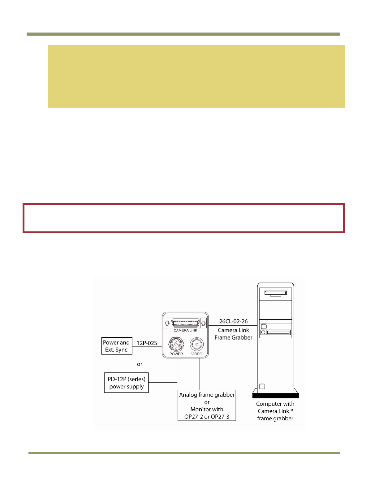
1.3 System Configuration
Figure 1 below presents a typical system configuration for the TM-9730CL camera.
Figure 1. TM-9730CL System Configuration.
2 Hardware Introduction
Page 11

TM/TMC/RM/RMC-97
30C
L
2 Installation
The following instructions are provided to help you to set up your camera quickly and easily. We
suggest that you read through these instructions before you unpack and set up your camera system.
2.1 Getting Started
2.1.1 Unpacking Instructions
We recommend that you save the original packing cartons for the cameras and accessories in case
you need to return or exchange an item.
We also recommend that you bench-test any equipment being sent to another location for field
installation to assure that everything is fully operational as a system.
2.1.2 Components List
Please begin by checking your order against the Components List shown below to assure that you
have received everything as ordered, and that nothing has been overlooked in the packing
materials. If any item is missing, please contact your JAI Inc. representative immediately.
• TM-9730CL camera
• Document download card (includes instructions on how to download the necessary
documentation and software)
2.1.3 Accessories and Options
Following is a list of additional accessories and options that may be required for your application.
Please check with your JAI Inc. representative before you install your camera to determine what you
might need.
• Digital output cable
− 26CL-02-26 (Camera Link cable)
Note: For CL models, the control software is downloadable. Serial communication is through the
Camera Link cable. No additional accessories are required.
• PD-12UUP series power supply (see Section 2.2.4 on page 7)
• 12P-02S power cable
• Tripod Mounting Kit: TP-20
(for dimensions go to:
www.jai.com/EN/CameraSolutions/Products/Accessories/Pages/Home.aspx
)
2.2 Camera Setup
2.2.1 Heat Dissipation
The TM-9730CL camera is a compact camera. Since all the electronics have been packed in a very
small package, the outer case of the camera gets hot due to heat dissipation. The TM-9730CL will
operate “stand alone”, but the following suggestions are recommended for optimum performance.
• Cooling fan to set-up positive air flow.
• Mount the camera on a large heat sink (camera bracket) made out of a conductive material such
as aluminum.
• Make sure the flow of heat from the camera case to the bracket is not blocked by a non-
conducting material like plastic.
• Make sure the camera has enough open space around it to facilitate the free flow of air.
Installation 3
Page 12
TM/TMC/RM/RMC-9730CL
NC
2.2.2 Connector Pin Configurations
2.2.2 (a) 12-Pin Connector
The TM-9730CL has a 12-pin Hirose connector for power input and signal integration. Pin #1 is
Ground and pin #2 is +12V DC. The pinout table is shown below. For the TM-9730CL, serial
communication camera control is done by means of the MDR26 Camera Link connector on the rear
panel of the camera
Table 1 Hirose power and signal integration.
Pin Description Pin
1 GND (power) 7
2 +12V DC 8
3 GND (analog) 9
4 Video out 10
5 GND (digital) 11
6 Reserved 12
OP25-3 – RS-232 on 12-pin
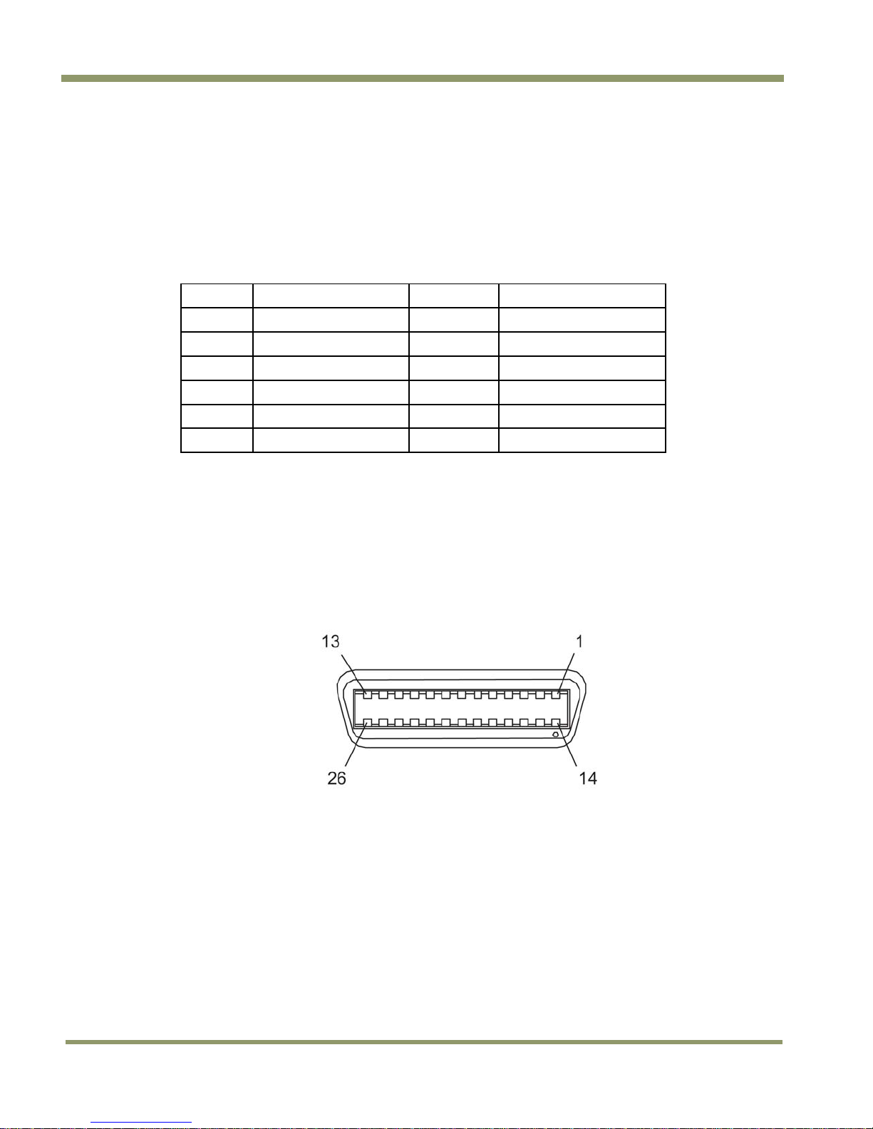
2.2.2 (b) Camera Link Connector
The TM-9730CL has a 26-pin connector on the rear panel to output Camera Link data. The connector
pin-out is shown in Table 2 below.
Description
VD in
Reserved
HD in
RXD (RS-232)*
TXD (RS-232)*
Figure 2. The 26-pin connector.
4 Installation
Page 13
TM/TMC/RM/RMC-97
30C
14
15
16
17
18
19
20
21
22
23
24
26
L
Table 2 26-pin Connector Pin Outs
Camera Link Connector MDR 26-pin Connector 10226-6212VC
Pin # Description I/O
1 GND
2 Tx OUT 0- Out
3 Tx OUT 1- Out
4 Tx OUT 2- Out
5 Tx CLK OUT- Out
6 Tx OUT 3- Out
7 SerTC+ In
8 SerTFG- Out
9 (CC1-) NC
10 (CC2+) NC
11 (CC3-) Ext VD-
12 (CC4+) Ext HD+ 25
13 GND
Pin #
Description
GND
Tx OUT 0+
Tx OUT 1+
Tx OUT 2+
Tx CLK OUT+
Tx OUT 3+
SerTC-
SerTFG+
(CC1+)
(CC2-)
(CC3+)
(CC4-)
GND
I/O
(Shield)
Out
Out
Out
Out
Out
In
Out
NC
NC
Ext VD+
Ext HD-
Note: SerTC: Differential Serial Communication to camera;
SerToFG: Differential Serial Communication to framegrabber.
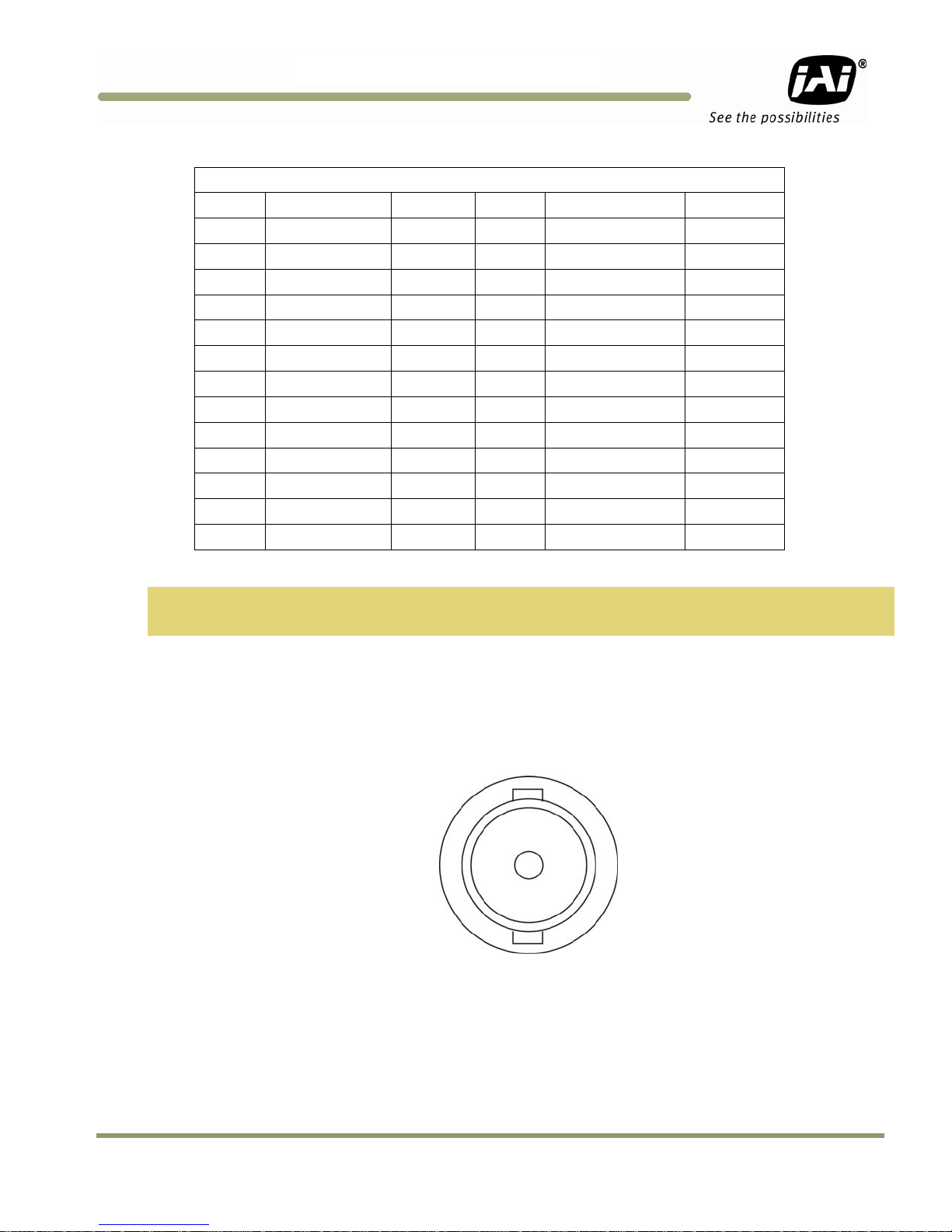
2.2.2 (c) Analog Output Connector
The TM-9730CL has a BNC connector on the rear panel to output non-standard progressive analog
video or RS-170 analog video (optional OP27-1) or NTSC analog video (optional OP27-2).
Figure 3. TM-9730CL BNC connector
Installation 5
Page 14
TM/TMC/RM/RMC-9730CL
Table 3 Software Controllable Shutter Speed and Times Table
Shutter
Number
0 no (1/30)
1 1/60
2 1/125
3 1/250
4 1/500
5 1/1,000
6 1/2,100
7 1/4,500
8 1/10,500
9 1/31,500
Shutter Exposure Time
Normal
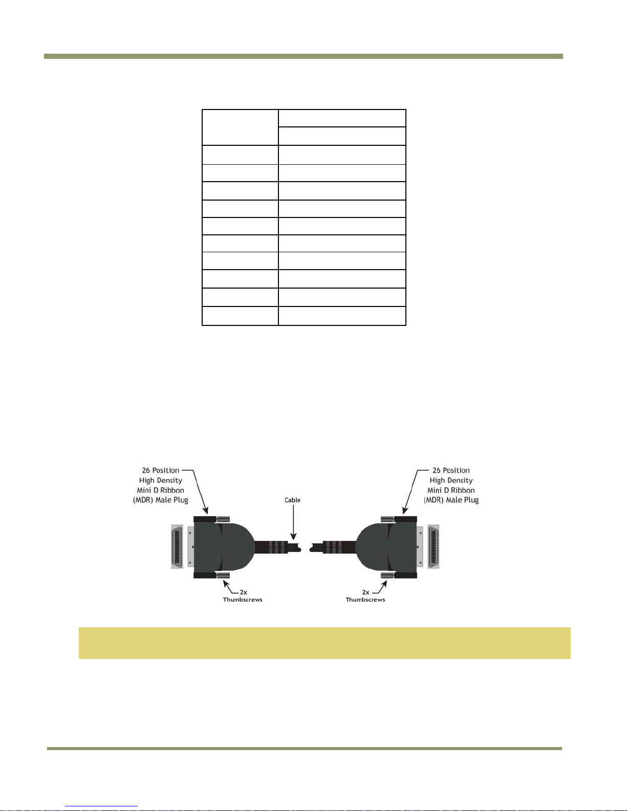
2.2.3 Camera Link Cable
The 26CL-02-26 cable assembly has been standardized as the Camera Link cable. This cable has the
26-pin connector on both ends. This is a straight-through cable. The pin-out configuration is shown
in Table 2 on page 5.
Figure 4. Camera Link Cable
Note: For TM-9730CL, serial communication for camera control is done by means of the Camera Link
connector on the rear panel of the camera.
Cable assemblies and board mount receptacles can be ordered from Intercon 1.
6 Installation
Page 15
TM/TMC/RM/RMC-97
30C
L
2.2.4 Power Supplies and Power Cable Setup
2.2.4 (a) Power Supplies
The TM-9730CL requires 12V DC power that is obtained through the 12-pin connector located on the
rear panel of the camera. JAI Inc. recommends the following power supplies:
PD-12UU 100-240V AC/12V DC 1.2A universal voltage power supply with
US plug (no 12-pin Hirose connector)
PD-12UUP 100-240V AC 1.2A universal voltage power supply with US
plug and 12-pin Hirose connector
PD-12UE 100-240V AC/12V DC 1.2A universal power supply with European plug
(no 12-pin Hirose connector)
PD-12UEP 100-240V AC/12V DC 1.2A universal power supply with European plug
and 12-pin Hirose connector
If you are providing power through the 12-pin connector, the PD-12UUP and PD-12UEP power
supplies are available with the 12-pin mating connector already attached to the leads from the
power supply. The PD-12UU or PD-12UE power supply can be connected to the JAI Inc. power cable
either directly or via a terminal strip.
When wiring the PD-12UU power supply directly, please note the following:
• The lead ends must be twisted together and tin-soldered for strength and electrical continuity.
• Shrink tubing or a similar insulator should be used to prevent exposed leads from touching and
shorting.
• The +12V lead is marked with a red stripe or white lettering; be sure not to reverse the leads.
• All connections must be properly insulated to prevent shorting.
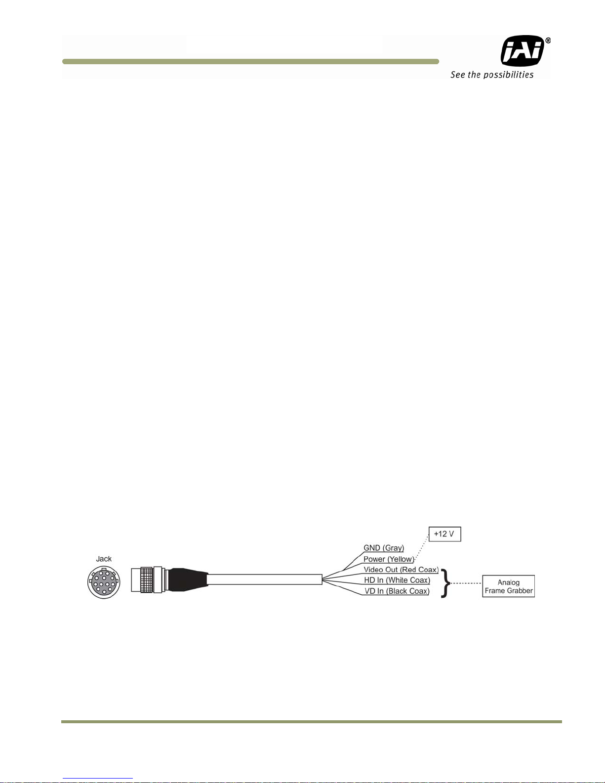
2.2.4 (b) JAI Inc. Power Cables
If you are using JAI Inc. power cables such as the 12P-02S, please refer to the 12-pin connector pinout diagram in “Hirose power and signal integration.” on page 4. The cable pin-out diagram is shown
in Figure 5 below. The color-coded leads use Gray for Ground and Yellow for +12V.
Figure 5. 12P-02S Interface Cable (optional)
Installation 7
Page 16

TM/TMC/RM/RMC-9730CL
7
8
9
10
11
12
Table 4 12P-02S Interface Cable
12P-02S Interface Cable
Pin# Lead Color Function
1 Gray GND
2 Yellow +12V DC
3 Red coax shield GND
4 Red coax Video
5 Orange coax shield GND
6 Orange coax NC
Note: Make sure that the unused leads are not touching and that there is no possibility that exposed
wires could cause the leads to short.
* Option OP27-3, NTSC Y/C output.
2.2.4 (c) Building Your Own Power Cable
Refer to the 12-pin connector pin-out in Section 2.2.2 (a on page 4. Connect the Ground lead to pin
#1, and the +12V DC lead to pin #2 of the 12-pin connector. Power must be DC-regulated, and of
sufficient current to properly power the camera.
Pin#
Lead Color
Black coax
White coax shield Reserved
White coax
Brown
Blue
Black coax shield
Function
VD Input
HD Input
NC / Y Output*
NC
NC / C Output*
2.2.4 (d) Attaching the Power Cable to the Connector
The 12-pin connector is keyed and will only fit in one orientation. Follow these directions to
properly attach the power cable to the camera connector:
1. Rotate the connector while applying slight pressure until the keyways line up.
2. Press the connector into place until firmly seated.
3. Plug the power cord into the AC socket. This will power the camera up.
2.2.5 Attaching the Analog Video Output
When connecting the TM-9730CL to an analog frame grabber or a multisync monitor, use the BNC
connector on the rear panel of the camera. The input of the monitor should be balanced for 75Ω
termination. Standard RG-59 type coaxial cable should carry a full video signal for up to 100 feet.
The multi-conductor cable 12P-02S from JAI Inc. can be used to transmit analog video, power, sync.
signals, and serial communication. The mini coaxial leads in JAI Inc. multi-conductor cables are
designed for short runs of no longer than 100 feet.
Note: Make sure that no extraneous wires are visible which could cause a short.
2.2.6 Attaching the Camera Lens
The TM-9730CL camera accepts 2/3" or larger format size C-mount lenses. To attach the C-mount
lens to the camera, carefully engage the threads and rotate the lens clockwise until it firmly seats
on the mounting ring. Do not force the lens if it does not seat properly. Please note that some
lenses with extremely long flangebacks may exceed the mounting depth of the camera.
8 Installation
Page 17
TM/TMC/RM/RMC-97
30C
L
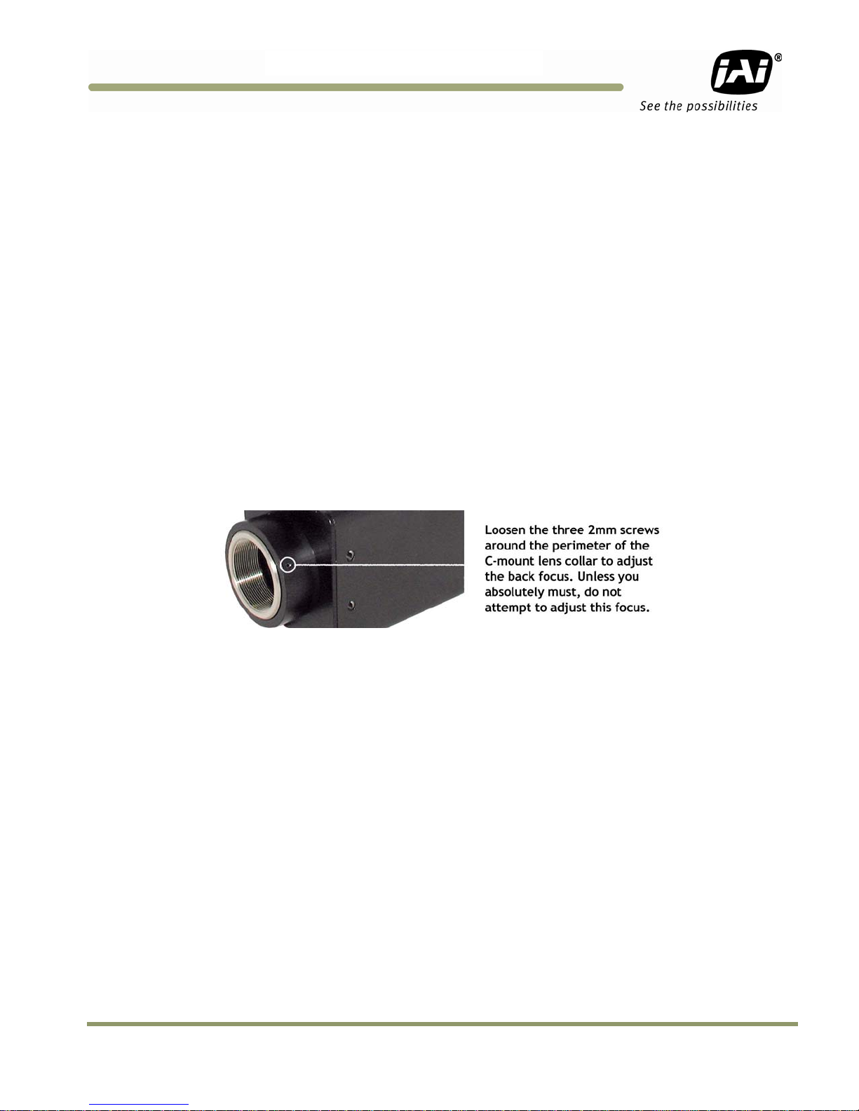
2.2.7 Adjustable Back-Focus
Before cameras are shipped, back focus is carefully set using a collimator, oscilloscope and other
specialized equipment. While the factory-set focus serves well in most cases, an adjustable back
focus makes it possible to improve image sharpness when using lower-cost zoom lenses, custom
optics, or in unusual parameters.
There should be an obvious need to refocus the lens before attempting to change the back focus.
This is an exacting task. Some cameras have been returned to the factory to reset the back focus
after failed attempts to change the focus by customers. It is wise to label cameras whose back focus
was adjusted.
4. The camera must be connected to a monitor before attempting to adjust the back focus.
5. To back focus the camera, first attach a C-mount lens in the mount. Be certain that the lens is
properly seated.
6. Next set the lens focus to infinity (if the lens is a manual iris, set the iris to a high f number
while still retaining a well illuminated image).
7. Loosen the three miniature hex set-screws (use a 0.9 mm hex wrench) that lock the focus ring in
place. Slowly turn the lens and focus ring assembly back and forth until you obtain the best
image of the desired object. This sets the back focus. Once the best image is obtained, tighten
the focus ring set-screws until they are snug. Do not over-tighten the screws.
Figure 6. Back Focus Set-Screw Locations
Installation 9
Page 18

3 Operation
3.1 Camera Back Panel
Figure 7. Camera Link back panel
TM/TMC/RM/RMC-9730CL
3.1.1 Digital Output Connector
Refer to Section 2.2.2 on page 4 for Camera Link information.
3.1.2 Analog Output Connector
The TM-9730CL camera has a BNC connector on the rear panel to output analog video data.
3.1.3 Power and External Sync Connector
Refer to Table 2 on page 5 for information on the power and external sync. connectors.
3.2 Progressive Scanning
Standard TV-system scanning is 525 lines interlace scanning as specified in the RS-170 protocol.
Every other horizontal line (odd lines and even lines) is scanned at a 60Hz rate per field, and the
scanning is completed with two fields (one frame) at 30Hz rate. Because of the interlace scanning,
the vertical resolution of CCD cameras is limited at 350 TV lines, regardless of the horizontal
resolution. When electronic shutter is applied, the CCD can hold only one field of charge at each
exposure. Therefore, the vertical resolution of the electronic-shutter camera is only 244 TV lines.
The situation is the same for an HDTV-format camera, since it has interlaced scanning and the
vertical resolution of the shuttered image is 500 lines.
The TM-9730CL uses a state-of-the-art progressive scanning interline transfer CCD which scans all
lines sequentially from top to bottom at one frame rate (30Hz). Like a non-interlace computer
screen, it generates a stable, crisp image without alternating lines and provides full vertical TV
resolution of 525 lines (a normal TV monitor display may not be able to show images due to monitor
scanning).
The interline transfer architecture is also important to generate simultaneous shuttering. This is
different from full frame transfer architecture which requires a mechanical shutter or strobe light in
order to freeze the object motion.
10 Operation
Page 19

TM/TMC/RM/RMC-97
30C
L
The TM-9730CL outputs the progressive scan image with an electronic shutter in two different
formats:
• Progressive scanning digital and analog output
The CCD signal goes through A/D and D/A converters and through 10-bit in, 8-bit out look-up table
(LUT). The digital output is available from 26-pin Camera Link connector.
The analog output is the same as 75 Ω, 1Vp-p format at 30Hz rate available from BNC and 12-pin
connector.
Note: Minimal blooming may occur due to the nature of the CCD.
3.3 Electronic Shutter
For more information about the electronic shutter, please see Section 1.2 on page 1.
3.4 Programmable Look-Up Table (LUT) and Knee Control
The TM-9730CL has a built-in LUT (look-up table) for dynamic range control.
At a specific gain setting, the offset (minimum level.... dark point) and A/D reference top voltage
(maximum level... saturation point) are set to 10-bit A/D input so that the full dynamic range of the
CCD is utilized at 10-bit references as the input and the LUT output is converted into 8-bit to adjust
the gamma correction.
Note: The knee LUT may not work with the Automatic Level Control since the results are unstable.
LUT selection:
• Linear / Gamma
• Knee LUT
− Pre-defined Knee LUT
− User defined Knee LUT
(Caution: Knee LUT may cause ALC function to be unstable)
3.5 Scan Modes
The TM-9730CL supports the following scan modes:
Figure 8. Progressive scan
3.5.1 Full Progressive Scan
The normal scan mode progressively scans a full frame of 768 x 484 pixels at 30 frames per second
using the standard 14.318MHz pixel clock and a single channel output. In contrast to interlace-scan
cameras, all of the 484 lines in the frame are exposed simultaneously per image capture.
Operation 11
Page 20

TM/TMC/RM/RMC-9730CL
3.6 External Sync
The TM-9730CL accepts an external sync of standard HD and VD at TTL level for general locking to a
system sync and clock. The external sync frequency requirement is as follows:
30 FPS
fHD = 15.73 KHz ±2%
fVD = 29.97 Hz ± 2%
Pixel clock = 14.318 MHz
3.7 3G Stagger Color Filter (Color Versions)
3.7.1 Color Filter Array
The color filter array is the staggered “3G” color mosaic filter pattern. The CFA contains 75% green
photosites and 25 red and blue photosites.
The digital format allows the camera to output accurate pixel data, including the color information.
When the data is stored in the frame buffer of a frame grabber or computer, the color information
is easily manipulated to restore the original color images. Because the color filter array contains
only a single R, G or B color in each pixel, the restored image has to fill in colors in the missing pixel
locations. The software uses neighboring pixel information to “guess” the missing colors to make
smooth, clear images. This is called “color interpolation.” Current high-speed computers allow such
color interpolation to be done almost in real time. Because these cameras do not contain internal
color-processing circuitry, 3G stagger cameras are smaller and less expensive than full-function
color cameras.
3.7.2 3G Stagger Color Filter Array (CFA)
It is critical for the framegrabber and color interpolation to know where the individual color pixels
exist relative to sync (LDV and FDV) timing.
This requirement makes digital output the preferred choice, because the timing relationships are
very accurate.
3.7.3 Interpolation Software
The color interpolation can be performed in the frame grabber or by using the host computer’s CPU.
Most major frame grabbers with processing capability provide tools for color interpolation. Software
vision packages also provide color interpolation capability, but speed and performance may be
determined by the PC’s resources and by the complexity of the interpolation routine.
3.7.4 Color Interpolation
The “3G stagger” pattern color filter array (CFA) consists of R, G, and B primary colors. Each pixel
represents one of three colors. In order to display or print color images, the signal has to be
converted to RGB output, which has three independent channels (outputs) and sync signals.
12 Operation
Page 21

TM/TMC/RM/RMC-97
30C
L
Figure 9. The 3G Stagger Pattern
Color interpolation software or firmware performs the color preprocessing by filling the missing
color pixels with neighboring pixels. It then separates the stream of data, (8-bit or 10-bit) into 3
(RGB) data (8-bit x 3) and adds the color matrix to adjust and balance each of the R,G, and B
channels (white balance or color balance).
The image quality depends on the camera’s own pixel data (including pixel data independency from
neighboring pixels, noise and color filter), and interpolation of the software algorithm such as 4 x 4
interpolation color matrix, white balance capability, etc.
All AccuPiXEL color cameras are carefully designed for maximum color performance. JAI Inc.
strongly suggests that you use digital output for the best performance.
Some software is used on-board (FPGA or DSP) to perform the interpolation. Other software simply
uses the host computer’s memory and CPU. The process speed may vary depending on the
architecture and speed of the computer.
Figure 10. CFA spectrum graph.
Operation 13
Page 22

TM/TMC/RM/RMC-9730CL
3.7.5 Starting Pixel Configuration
All manufacturers produce similar CFAs, but there are slight differences between the CCDs produced
by different manufacturers. The first line is generally R and G. The Sony CCD starts with R. The
camera timing can be adjusted to start with either G or R by skipping the very first pixels at each
lines. The majority of color interpolation software can select between a variety of pixel relations,
such as R/G start or G/R start, as well as G/B start and B/G start. Once the correct scanning is
configured, the rest of the interpolation will be exactly the same. Please contact JAI Inc. for further
information regarding CCD manufacturers.
Figure 11. CFA configuration options
3.7.6 Sync and Data
The individual color data is exactly the same as the pixel data. This means that the timing
relationships of the color cameras are also the same as of the B/W cameras.
For a detailed timing chart, please refer to each B/W camera’s data sheet and manual.
If the frame grabber has a standard B/W configuration file, then AccuPiXEL color cameras can use
that configuration file to operate. Please consult JAI Inc., or your framegrabber supplier for
compatibility information.
14 Operation
Page 23

TM/TMC/RM/RMC-97
30C
L
Figure 12. Example of the TMC-9730CL (progressive scan output).
It is important to meet the exact starting pixel at LDV and the starting line of FDV. If the starting
pixel or line is shifted due to the image capture configuration, then the interpolation software can
be adjusted for the correct starting point. In figure A, if the first pixel is shifted (missed), the color
interpolation should start with G-R. If the first line is missed in A, the interpolation order will be BG.
3.7.7 Camera Functions
AccuPiXEL color cameras perform all functions the same way as B/W cameras. However, because of
color characteristics, the following issues are different:
• LUT (Look-up Table)
LUT is a powerful tool to adjust the dynamic range as well as color dynamic range. Since human
color perception is non-linear, LUT selection can help optimize color contrast by selecting the LUT
value. Gamma 0.45 is logarithmic and is closed to human perception.
When LUT is selected, black-level may vary slightly, adjusting V (bottom) may be necessary.
Operation 15
Page 24

3.8 Camera Timing Charts
TM/TMC/RM/RMC-9730CL
16 Operation
Page 25

TM/TMC/RM/RMC-97
30C
L
Operation 17
Page 26

4 Troubleshooting
4.1 Problems and Solutions
Following are troubleshooting tips for common problems. In general, problems can easily be solved
by following these instructions. If the following remedies fail to offer a solution to your problems,
please contact a JAI Inc. representative.
4.1.1 Symptom: No Video
Remedies: Check that the following are properly connected and operational.
• Power supplies
• Power cables
• Main power source
• Shutter control
• Lens
• Digital output cable
• Analog video cable
4.1.2 Symptom: Dark Video
Remedies: Check that the following are properly connected and operational.
TM/TMC/RM/RMC-9730CL
• Shutter selection
• Iris opening on the lens
4.1.3 Symptom: Non-Synchronized Video
Remedies: Check that the following are properly connected and operational.
• Proper mode output
• Frame grabber software camera selection
Note: Breaking the factory seal without prior approval from the factory will void the product
warranty.
4.2 Information and Support Resources
For further information and support:
Phone: (408) 383-0300
(800) 445-5444
Fax: (408) 383-0301
Mail: JAI, Inc.
Sales Department
625 River Oaks Parkway
San Jose, CA 95134
ATTN: Video Applications
Web Site: www.jai.com
18 Operation
Page 27

TM/TMC/RM/RMC-97
30C
L
5 Camera Specifications
Table 5 Specifications
Model TM-9730CL Series
Imager TM-9730CL
TMC-9730CL
Active Area 8.9mm (H) x 6.6mm (V)
Active Pixels 768 (H) x 484 (V)
Cell size 11.6µm x 13.6µm
Scanning (Active Pixels) 768 (H) x 484 (V) @ 30 Hz
Sync
Data Clock Output 14.318 MHz
Resolution
S/N Ratio ≥ 54dB
Min Illumination 1.0 lux, f=1.4 (no shutter) @ 30fps
Monochrome - 2/3" progressive scan interline transfer CCD
Color – 2/3” progressive scan interline transfer Bayer CCD
Internal/external auto switch
HD/VD, 4.0 V impedance 4.7K Ω
30Hz±5% non-interlace
HD= 15.734 kHz±5%
Digital: 768 (H) x 484 (V)
Analog; over 570 TV lines (H) x 484 TV lines (V)
Video Output
Gamma Programmable LUT (1.0 std.)
Lens Mount C-mount (adjustable)
Power Req 12V DC±10%, 330 mA (typical at 25° C)
Operating temperature
Extended temperature
Random vibration 7Grms (10Hz to 2000Hz)
Shock 70G, 10-11 msec
Size (W x H x L) 44.5mm x 44.5mm x 68.3mm without connectors
Weight
Optional Functions
Optional Accessories
I/O CL
Power cable
Power supply
Tripod Mounting Kit
Analog: 714mV, 75 Ω Progressive Scan (Non-interlace)
Camera Link: (8 bit)
Full performance: -10°C to 50°C
-40°C to +65°C (reduced performance may occur)(OP22-5-1)
Standard camera without tripod mount: 171 g, 6.0 oz. (TM-9730CL),
Standard camera with tripod mount: 183.2 g, 6.5 oz. (TM-9730CL)
Digital Zoom camera without tripod mount: 184.4 g, 6.5 oz. (TM-9730CL),
Digital Zoom camera with tripod mount: 197.2 g, 7.0 oz. (TM-9730CL)
Auto Level Control (ALC[EE & AGC])(OP1-5): Imager Blemish Map (OP2-1):
Blemish Compensation (monochrome)(OP2-5): UV Imager (monochrome)
(OP21-UV): Conformal Coat (OP22-5-5): RS-232 on 12P (OP25-3): Analog
frame buffer & RS-170 video conversion (OP27-1): NTSC Y/C output (color
only)(OP27-2): Y/C output (color only) (OP27-3): Digital Zoom 2:1
(monochrome only)(TBD) (OP60-2)
26CL-02-26 Camera Link cable (2m)
12P-02S power cable with open leads (2m)
PD-12UUP series (includes power connector)
TP-20
Camera Specifications 19
Page 28

5.1 Physical Dimensions
Figure 13. Physical Dimensions
TM/TMC/RM/RMC-9730CL
Caution: When mounting the camera to any fixture, do not use screws that extend more than 5 mm into the
camera housing to avoid possible damage to the internal circuitry. For attaching the tripod
mounting plate, only the supplied screws should be used.
20 Camera Specifications
Page 29

TM/TMC/RM/RMC-97
30C
L
5.2 Spectral Response
Figure 14. Monochrome Spectral Response
Figure 15. Color Spectral Response
Camera Specifications 21
Page 30

Page 31

TM/TMC/RM/RMC-97
30C
L
6 Introduction
The AccuPiXEL series cameras are high resolution, progressive scan cameras with JAI-proprietary
LUT control and other excellent features. The camera control software was developed to function as
standard software for the entire AccuPiXEL series. This software can open either the RS-232 serial
port (COM) or Camera Link. Camera Link users must physically install the Camera Link frame grabber
board into the PC. Also install the Camera Link API (clserXXX.dll) software. These cameras are
specially designed to capture images in progressive scan (non-interlace) format, producing a full
frame of electronic shutter images, as well as normal images. This document addresses the
AccuPiXEL version 5.0.0 software, last modified in 2007 and available for download at www.jai.com.
2.Camera-Control Software
6.1 Software Installation
Following are instructions to install the AccuPiXEL series camera-control software on a PC.
6.1.1 Before Installing the AccuPiXEL Series Camera-Control Software
Before installing the AccuPiXEL series Camera-Control Software, please note the following.
• The AccuPiXEL camera-control software is tested for Microsoft Windows 2000 and XP operating
systems.
• We recommend that you use small fonts for the Display Properties dialog box in the control
panel.
• The AccuPiXEL series camera-control software requires one free communication port that is not
in conflict with other peripherals such as the mouse or modem.
• Installation of the AccuPiXEL series camera-control software requires 2.0 MB of free space on
your PC hard disk.
• Uninstall any previous versions of AccuPiXEL on the hard drive. See Section 6.1.4 on page 27.
6.1.2 Installing the Software
To install the AccuPiXEL series camera-control software, follow the steps below.
1. Download the AccuPiXEL software from the JAI web site at www.jai.com.
Locate the software by going to the camera description, clicking on the Software link, or
searching AccuPiXEL using the site search feature.
2. Click on the “Save” button to save a compressed copy of the software to the hard drive of your
system. Do not confuse AccuPiXEL with dual-tap AccuPiXEL software.
Software Introduction 23
Page 32

TM/TMC/RM/RMC-9730CL
Note: If you go to software and download based on the camera description, for example, TM-9730CL,
the software download is the correct, and latest released version.
Figure 16. Use Save to download a copy of the software.
The software is compressed, and it may be necessary to install decompression software if you are
using an older operating system.
Use decompression software to create the installation software directory.
Figure 17. Select and Extract the compressed files.
24 Software Introduction
Page 33

TM/TMC/RM/RMC-97
30C
L
Figure 18. The extraction creates a directory named “69-0094 rev C”
3. Open the directory and double-click on setup to begin the install.
4. Follow the installation instructions.
Note: You can change the installation directory if you want.
6.1.3 Installing the Camera Link API DLL (clserXXX.dll)
To install the Camera Link control software with frame grabber software, please consult the frame
grabber company or JAI Inc.
The AccuPiXEL software does not function if a frame grabber can not be located. The current JAI
Cam2Net software installs the frame grabber dll “clsrc2n.dll”. For more details on compatible frame
grabbers see the “ReadMe” file in the “69-0094 rev C” directory created from the AccuPiXEL
download.
6.1.4 Uninstalling the Software
You might want to uninstall the previous version of AccuPiXEL before installing version 4.4.1 You can
uninstall the AccuPiXEL series camera-control software from the control panel. To uninstall, follow
the steps below.
1. Open “Add or Remove Programs” in the control panel.
2. Select the old version of AccuPiXEL camera software from the list of installed software.
3. Click the “Change/Remove” button, then click “Yes” to confirm.
Software Introduction 25
Page 34

TM/TMC/RM/RMC-9730CL
Figure 19. Use Add/Remove to uninstall AccuPiXEL software.
6.1.5 Accessing the AccuPiXEL software
Once the software has installed go to the “Start” menu on the main screen to run AccuPiXEL. Click
on All Programs>AccuPiXEL Camera V5.0.0>AccuPiXEL Camera. This opens the small selection dialog
box used to configure the camera to run AccuPiXEL.
Figure 20. The Start Menu gives easy access to the AccuPiXEL software.
6.1.6 Connection
A dialog box opens to allow interface selection. Select ComPort and enter port number that the
camera is connected to. (User should be familiar with their PC ComPorts settings.)
6.1.7 Framegrabber Choices
The function choices are ComPort, CamLink 1.0 and CamLink 1.1. Choose either CamLink 1.0 or
CamLink 1.1.
Select Frame Grabber board index. This index is for users who install multiple Camera Link
framegrabbers. For a single board user, the index is selected as zero for default.
26 Software Introduction
Page 35

TM/TMC/RM/RMC-97
30C
L
Figure 21. Choose a framegrabber version, verify Board Index; click GO!
6.1.8 CamLink 1.0
When you choose the CamLink 1.0 version it is necessary for you to locate and double-click to link
the framegrabber DLL. Once the DLL is linked choose the matching camera series. In this case the
TM-9730CL.
Figure 22. Choose the matching configuration file for the software.
Software Introduction 27
Page 36

TM/TMC/RM/RMC-9730CL
6.1.9 CamLink 1.1
If you select CamLink 1.1 the software searches for all CamLink 1.1 compliant frame grabbers. The
AccuPiXEL software displays available frame grabber DLL’s. Choose the framegrabber the camera is
connected to and click on the GO! button.
Figure 23. AccuPiXEL displays framegrabber DLLs.
6.1.10 Choose the appropriate camera.
The AccuPiXEL software opens a default folder to allow you to select the camera using the software.
Be sure to select the correct camera description.
Figure 24. Select the camera connected to the system.
The main menu opens once the camera and DLL configurations are correct. See “GUI Features” on
page 31 for details on using the interface to configure the camera.
28 Software Introduction
Page 37

TM/TMC/RM/RMC-97
30C
L
7 GUI Features
The AccuPiXEL series Camera Link software communicates through the Camera Link connector on
the back panel of the camera.
7.1 Menu Bar
Camera Output Protocol
About
Most of these menu bar options are set up
in the process of opening the main screen.
They are detailed later on in this document.
7.2 Main Screen
Exposure Control
• Shutter Mode
• Shutter Switch
Gain Control
• Gain
Blemish Correction (OP2-5)
Auto Level Control
Table Selection
• Linear Selection
• Knee Selection
• Gamma Selection
RX
TX
EEPROM
• Page
• Current
• User
GUI Menu Bar 29
Page 38

TM/TMC/RM/RMC-9730CL
7.3 Operating The Control Software
7.3.1 Exposure Control
In Exposure Control, you can specify the shutter mode. Scan mode is deactivated for the TM-9730CL.
7.3.1 (a) Shutter Mode
In the Shutter Mode drop-down list box you can select No Shutter mode, Manual, or Direct shutter.
Figure 25. Shutter Mode drop-down list box.
7.3.1 (b) Shutter Time
Use the Shutter Switch drop-down list box to select a pre-configured shutter speed.
Figure 26. The Shutter Switch drop-down list box.
7.3.1 (c) Direct
The Direct drop-down list box allows you to select camera speed using a slider. The camera must be
in Direct Shutter Mode. The Shutter Switch is disabled when Direct is active.
30 Software Introduction
Page 39

TM/TMC/RM/RMC-97
30C
L
Figure 27. Setting Direct Exposure Control
7.3.2 Gain Control
This control is available when the on/off checkbox in the Auto Level Control is not checked. Auto
Level Control; Gain Control. The Gain Control box allows you to change the Gain value from 0 to 255
(integer). To change the value, move the slider, or enter the value directly into the text box.
Figure 28. Gain Controls
7.3.2 (a) V-Top
The V(top) box allows you to change the V(top) value of the A/D converter from 30% to 85%
(integer). To change the value, move the slider or enter the value directly into the text box. The
scale goes from zero to 255.
7.3.2 (b) V-Bottom
The V(bottom) box allows you to change the V(bottom) value of the A/D converter from 0 to 100%
(integer). To change the value, move the slider or enter the value directly into the text box.
Note: Gain Control is enabled or disabled based on several conditions. If a camera is purchased
without Auto Level Control (ALC) the gain control is always available. If the camera has the
ALC option, Gain Control is turned off by the software because the ALC automatically
overrides any manual settings. If ALC is present the user can turn off the Auto Level Control
which then activates the Gain Control.
7.3.3 Blemish Correction (Optional-OP2-5)
The Blemish Correction control helps compensate for any irregularities in the CCD which might
adversely affect the image quality. If desired the control can be turned off using the radio buttons.
GUI Menu Bar 31
Page 40

TM/TMC/RM/RMC-9730CL
Figure 29. Blemish Correction Radio Buttons
7.3.4 Auto Level Settings
Verify the on/off checkbox is checked to activate the Auto Level Control if the camera has the ALC
option.
Figure 30. Auto Level Control
7.3.4 (a) Setting the ALC
Click the Configure button.
Set the Gain, Desired Lvl, and Tuning Factor and click Save Settings. The Load Default button allows
access to stored settings.
Figure 31. Active Auto Level Control
7.3.5 Table Selection
The Table Selection box allows you to select linear, knee, or gamma 0.45 camera output.
32 Software Introduction
Page 41

TM/TMC/RM/RMC-97
30C
L
Figure 32. Look Up Table options.
7.3.5 (a) Knee Selection
The Knee Selection box allows you to select the pre-set knee control Look Up Table (LUT). The
AccuPiXEL series cameras have eight preset knee control LUTs.
Note: The use of the Knee LUT may interfere with the Auto Level Control (ALC).
Figure 33. Knee Selections
7.3.5 (b) Knee Control
The Knee Control graphical control allows you to change two knee point values visually by clicking
and dragging the “knee line.” You may enter X1, Y1, X2, Y2 values directly to adjust the knee curve.
When you have chosen the value you want and are ready to set this value to the camera, click the
“Send Knees” button.
GUI Menu Bar 33
Page 42

TM/TMC/RM/RMC-9730CL
Figure 34. Graphical Knee Selections
7.3.5 (c) Table
The A and B designations access two different memory locations for loading knees from a table.
7.3.5 (d) X1, X2, Y1, Y2
The X and Y controls left of the graphical knee control allow LUT configuration by entering numbers
instead of dragging on the graphical control. This is useful when the desired LUT settings are known.
Use the Send Knees button to implement settings.
Figure 35. Sending Knee Settings
7.3.6 EEPROM Settings
The EEPROM settings can be accessed, restored, and saved using the main menu. The current page
(Current) or a setting stored in memory (Page) can be accessed by clicking the appropriate radio
button, selecting the page number, and then choosing the button for the desired functionality.
The Report button provides all of the saved or current information, depending on the setting. Load
makes a stored configuration the active configuration. Write creates a new setting; if a setting
34 Software Introduction
Page 43

TM/TMC/RM/RMC-97
30C
L
already exists it is overwritten, with certain exceptions. Info provides the details about a
configuration, but does not load the configuration. Default opens the settings used for camera
startup from a new boot.
Figure 36. EEPROM access from the main menu
GUI Menu Bar 35
Page 44
8 GUI Menu Bar
The “Load” option in the menu bar allows you to restore the Gain Table setting from EEPROM. Click
on “Load” and select “From Gain Table” in the menu to restore the setting from four user memory
pages and four preset setting memory pages. See “EEPROM Settings” on page 37.
8.1 Camera Output Protocol
Figure 37. Buffer Size
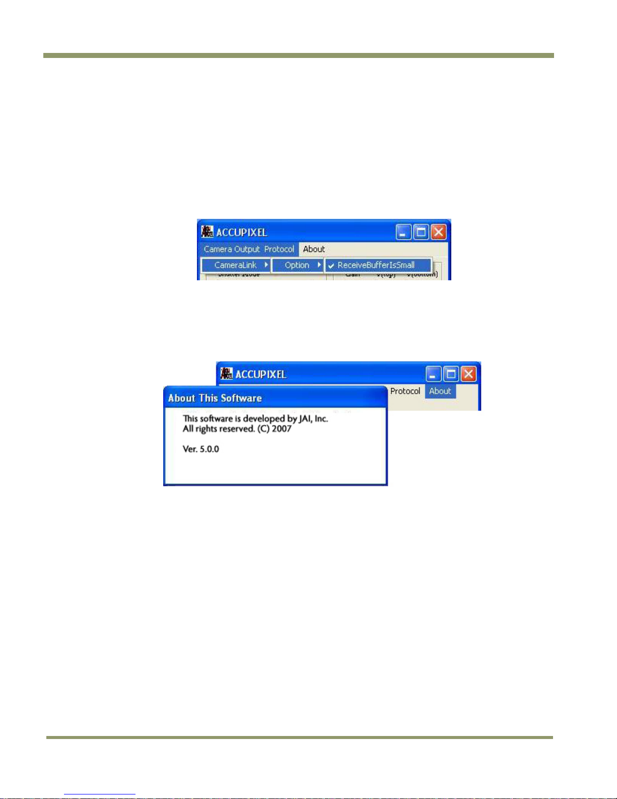
8.2 “About” Menu
Click on the About menu to view current software version details.
TM/TMC/RM/RMC-9730CL
Figure 38. Software version details
36 Customer & Serial Commands
Page 45

TM/TMC/RM/RMC-97
30C
r
L
9 AccuPiXEL Series Camera Customer and Serial Commands
The AccuPiXEL series cameras can be controlled by serial command either by means of RS-232 or
Camera Link. The Start character is always “:” and the End character is always <CR> (return). For
example, to set Asynchronous Pulse Width Mode, send the command :SA9<CR> to the camera. The
following table contains serial commands that can be used to control the camera.
Table 6 Auto Level Control Commands (Optional-OP1-5)
Command Description Response
:ALC0<cr> Disable Auto Level Control
:ALC1<cr> Enable Auto Level Control
:ALC?<cr> Enquire Status of
Auto Level Control
:G0=[xx]<cr> Set Default Gain for
ALC:xx=H100H1FF
:G0?<cr> Enquire Default Gain for ALC :<ack>G0=[xx]<cr>
K1=[xx]<cr> Set Tuning Factor K1:H100-
H1FF
:<ack><cr>
:<ack><cr>
:<ack>ALC[x]<cr>
:<ack><cr>
:<ack><cr>
Comments
x=0 (disabled)
1 (enabled)
If xx is too high or too low ALC
may be unstable.
xx=H100-H1FF
Value must compromise both
response time and stability of
ALC performance
:K1?<cr> Enquire Tuning Facto
:X0=[xx]<cr> Set Desired Level of
ALC:xx=H100-H1FF
:X0?<cr> Enquire Desired Level of ALC :<ack>X0=[xx]<cr>
:STF<cr> Save user tuning factors
:LTF<cr> Load user tuning factors
:LTF0<cr> Load factory default tuning
factors
:LOG0<cr> Set to linear average detection
for ALC
:LOG1<cr> Set to Log average detection
for ALC
:LOG?<cr> Enquire if current user is
linear or log
:<ack>K1=[xx]<cr>
:<ack><cr>
:<ack><cr>
:<ack><cr>
:<ack><cr>
:<ack><cr>
:<ack><cr>
:<ack>LOG[x]<cr>
xx= H100-H1FF
If xx is too high or too low ALC
may be unstable
xx=H100-H1FF
X=0 (linear)
1 (log)
Customer & Serial Commands 37
Page 46

TM/TMC/RM/RMC-9730CL
K
ACK
ACK
ACK
ACK
ACK
ACK
ACK
ACK
ACK
ACK
ACK
ACK
ACK
ACK
K
K
K
K
K
ACK
Table 7 Serial Commands Table
First
Character
1 “S” (Shutter) “M” (Manual) “0” – “9” Mode AC
2 “G” (Gain) “M” “00” – “FF”
3 “V” (A/D Vref) “T” (Top) “00” – “FF”
4 “W” (Write) “P” (Page) “0” – “6”
“U” (User) “A” – “D”
5 “L” “P” (Page) “0” – “6”
“U” (User) “A” – “D”
6 “R” (Report) “P” (Page) “0” – “6”
“U” (User) “A” – “D”
Second
Character
“X” “000” – “419”
“B” (Bottom) “00” – “FF”
“S” (System) “A” – “D”
“S” (System) “A” – “D”
“N” (kNee) “0” – “9”
Third
Character
Response Functions
Manual Shutter Mode
Direct Shutter Mode
Gain Control
Vtop reference setting
Vbtm reference setting
Write current setting to Page EEPROM
Write current setting to User EEPROM
Write current setting to System
EEPROM
Restore setting from Page EEPROM
Restore setting from User EEPROM
Restore setting from System EEPROM
Load Preset Knee Table
ACK + “P” + (“9” – “F”) + 16 bytes
ACK + “U” + (“A” – “D”) + 6 bytes
“S” (System) “A” – “D”
“R” (Current) AC
“X” (Execute) AC
“D” (Date) Info
7 “T” (Table) “N” (kNee) X1 + Y1 + X2 +
Y2
“M” (Gamma) AC
“L” (Linear) AC
“C” (Switch A,
B Table)
Note: One byte of data consists of two ASCII codes. For example, 0x3A is “3” (0 x 33)
and “A” (0 x 41). <ACK> is 0 x 06. <NAK> is 0 x 15. <CR> is 0 x 0D.
Note: 1-byte data is represented in 2 ASCII characters, e.g. 0x3A is “3A” or 0x3341.
<CR> = 0x0DCommand or response terminator
<ACK> = 0x06Command accepted
<NAK> = 0x15Command not accepted
RS Command: RR<CR>
RS Return: RR + “16 bytes” + <CR>
“0” or “1”
AC
ACK + “S” + (“A” – “D”) + (6 bytes)
ACK + “RR” + 16 bytes
Set Camera with loaded data
Report CPU program version
(X1, Y1) coordinate for knee 1
X1, Y1, X2, Y2: “00 – FF”
(X2, Y2) coordinate for knee 2
38 Customer & Serial Commands
Page 47

TM/TMC/RM/RMC-97
30C
--
--
--
A
A
A
A
--
--
L
Table 8 16 Bytes Status Report
Byte 1 MGCL (1 byte)
Byte 2 Vtop(1 byte)
Byte 3 Vbtm(1 byte)
Byte 4 XA1 (1 byte) --
Byte 5 YA1 (1 byte) --
Byte 6 XA2 (1 byte) --
Byte 7 YA2 (1 byte) --
Byte 8 XB1 --
Byte 9 YB1 --
Byte 10 XB2 --
Byte 11 YB2 --
CDS Gain
A/D reference voltage Top
A/D reference voltage Bottom
X-Coordinate of right knee for table
Y-Coordinate of right knee for table
X-Coordinate of right knee for table
Y-Coordinate of right knee for table
X-Coordinate of left knee for table B
Y-Coordinate of left knee for table B
X-Coordinate of left knee for table B
Y-Coordinate of left knee for table B
Byte 12 FUNCFLAG1 (1 byte) --
Byte 13 FUNCFLAG2 (1 byte) --
function flag #1
function flag #2
Byte 14 SHTRNUM (1 byte)
Byte 15, 16 SHTRVAL (2 byte)
current shutter number
manual/direct shutter value
Table 9 Function Flag Description 1
BIT 7 6 5 4 3 2 1 0
FUNC-
FLAG #1
SHTR2FLG (Bit3) -- 00 - (0) no shutter, 01 - (1) normal shutter
SHTR1FLG (Bit2) -- 10 - (2) direct shutter, 11- (3) async shutter
MSEL2FLG (Bit1) -- 00 - (0) normal scan, 01 - (1) partial scan #1 (optional)
MSEL1FLG (Bit0) -- 10 - (0) normal scan, #2 (optional), 11-(3) two-row scan
LOGAVG=
0-Linear Avg
1-Log Avg
ALCFLG=
0=Off,
1-On
BLMFLG
Blemish
Compensation=
0-Off, 1-On
Resv SHTR2
FLG
SHTR1
FLG
MSEL2
FLG
MSEL1
FLG
Customer & Serial Commands 39
Page 48

TM/TMC/RM/RMC-9730CL
Table 10 Function Flag Description 2
BIT 7 6 5 4 3 2 1 0
FUNC-
FLAG #2
RS-170 TSELFLG Resv LUTB2FLG LUTB1FLG Resv LUTA2FLG LUTA1FLG
TSELFLG (Bit4) -- 0 - Select table A, 1 - Select table B
LUTB2FLG (Bit3) -- 00 - Linear mode; 01 - Knee mode (for table B)
LUTB1FLG (Bit2) --10 - Gamma mode; 11 - Direct input mode (reserved)
LUTA2FLG (Bit1) -- 00 - Linear mode; 01 - Knee mode (for table A)
LUTA1FLG (Bit0) -- 10 - Gamma mode; 11 - Direct input mode (reserved)
RS-170=0-Progressive, 1-Interlace
40 Customer & Serial Commands
Page 49

TM/TMC/RM/RMC-97
30C
L
10 Configurable Order Options
10.1 OP1-5 ALC (Automatic Level Control)
ALC keeps the average of output level to a specific value (available for users to specify). ALC is
achieved by implementing both AGC (automatic gain control) and AEC (automatic exposure control).
AGC controls gain from 8dB to 28dB. AEC controls exposure time from 31.8uS to 33.3mS. Therefore,
the camera is possible to work at a very wide dynamic range (10000:1).
Note: When ALC is active, LUT must be either Linear or Gamma .45. Selecting any other knee control
LUT may cause an unstable result.
10.2 OP2-1 Imager Blemish Map
10.3 OP2-5 Blemish Correction (monochrome only)
In an attempt to provide blemish free images the TM-9730CL has a built-in blemish correction
feature. Through a calibration process, all blemished pixels are detected and their positions are
stored in an EEPROM in the camera. The known blemished pixels are corrected by replacing the
value of the nearest neighbor pixels. This feature is only available in monochrome cameras.
10.4 OP21-UV UV Imager(monochrome only)
Microlensless and glassless imager. No imager warranty with this option.
10.5 OP22-5-1 Extended Temperature
-40°C — +65°C (reduced performance may occur).
10.6 OP22-5-5 Conformal Coat
10.7 OP25-3 RS-232 on 12P
Not available with Y/C (OP27-3)
10.8 OP27-1 RS-170 Video Timing
Analog frame buffer for RS-170 video conversion for local monitors, recorders, or other video
standard equipment.
Configurable Options 41
Page 50

TM/TMC/RM/RMC-9730CL
Figure 39. Frame Timing Chart
Figure 40. Line Timing Chart
42 Configurable Options
Page 51

TM/TMC/RM/RMC-97
30C
L
10.9 OP27-2 NTSC (color only)
NTSC composite video. Active video is 708 (H) x 480 (V).
Figure 41. NTSC Composite Video Levels
Configurable Options 43
Page 52

TM/TMC/RM/RMC-9730CL
10.10 OP27-3 NTSC Y/C output (color only)
NTSC Y/C has better performance since it separates luma and chroma signals. Y/C output is from
the 12-pin Hirose connector.
Pin 10 is Y (luma) Pin 12 is C (chroma)
Figure 42. NTSC Video Levels
10.11 OP60-2 Digital Zoom 2:1 (monochrome only)
Digital zoom takes image information from a portion (or subset) of the pixels in the CCD and
enlarges the pixels to fill the entire display. Information from the CCD pixels not used for the digital
zoom is discarded.
The TM-9730CL is capable of a maximum of 3x zoom, which uses one third (256 x 162 pixel area) of
the CCD. This option is offered for monochrome cameras only.
44 Configurable Options
Page 53

Page 54

Europe, Middle East & Africa
Phone +45 4457 8888
Fax +45 4491 8880
Asia Pacific
Phone +81 45 440 0154
Fax +81 45 440 0166
Americas
Phone (Toll-Free) 1 800 445-5444
Phone +1 408 383-0301
www.jai.com
 Loading...