

JAI SW-4000Q-10GE, SW-4000T-10GE User Manual

User Manual
SW-4000Q-10GE
4CMOS Prism Linescan Camera
Document Version: 1.0
SW-4000Q-10GE_Ver.1.0 _Apr.2019
Thank you for purchasing this product.
Be sure to read this manual before use.
This manual includes important safety precautions and instructions on how to operate the unit. Be sure to read
this manual to ensure proper operation.
The contents of this manual are subject to change without notice for the purpose of improvement.
© 2019 JAI

Contents
36
36
37
38
40
40
41
42
42
43
43
44
45
46
46
58
58
59
61
62
64
65
66
67
SW-4000Q-10GE
Notice/Warranty/Certifications
Usage Precautions
Features
Parts Identifications
Preparation
Preparation Process
Step 1:Installing the Software
Step 2:Connecting Devices
Step 3:Verifying Camera Operation
Step 4:Verifying the Connection between
the Camera and PC
Step 5:Changing the Camera Settings
Step 6:Adjusting the Image Quality
Step 7:Saving the Settings
Main Functions
Valid Input / Output Combinations
GPIO(Digital Input/Output Settings)
Pixel Format
ExposureMode
Image Output Timing
Pixel Sensitivity Correction
Gain Control
Lookup Table (LUT)
Gamma Function
ShadingCorrection
Black Level Correction
Variable Line Rate
Electronic Shutter
12
12
12
13
15
15
18
20
21
23
23
24
25
27
27
31
32
33
34
35
35
36
36
3
5
7
8
EEN (Exposure Enable) Function
Test Pattern Function
Color Space Conversion
Counter And Timer Control Function
Chromatic Aberration Correction
Connecting Rotary Encoders
Frame Start Trigger
Binning Function
ROI (Regional Scanning Function)
Chunk Data Function
Delayed Readout
Event Control Function
Action Control Function
Setting List
Feature Properties
Miscellaneous
Troubleshooting
Specifications
Spectral Response
Dimensions
Comparison of the Decibel Display and
Multiplier Display
User’s Record
Index
Revision history
— 2 —

SW-4000Q-10GE
Notice
The material contained in this manual consists of information that is proprietary to JAI Ltd., Japan and may only
be used by the purchasers of the product. JAI Ltd., Japan makes no warranty for the use of its product and
assumes no responsibility for any errors which may appear or for damages resulting from the use of the
information contained herein. JAI Ltd., Japan reserves the right to make changes without notice.
Company and product names mentioned in this manual are trademarks or registered trademarks of their
respective owners.
Warranty
For information about the warranty, please contact your factory representative.
Certifications
CE compliance
As defined by the Directive 2004/108/EC of the European Parliament and of the Council, EMC (Electromagnetic
compatibility), JAI Ltd., Japan declares that SW-4000Q-10GE complies with the following provisions applying to
its standards.
EN 61000-6-3 (Generic emission standard part 1)
EN 61000-6-2 (Generic immunity standard part 1)
FCC
This equipment has been tested and found to comply with the limits for a Class B digital device, pursuant to Part
15 of the FCC Rules. These limits are designed to provide reasonable protection against harmful interference in
a residential installation. This equipment generates, uses and can radiate radio frequency energy and, if not
installed and used in accordance with the instructions, may cause harmful interference to radio communications.
However, there is no guarantee that interference will not occur in a particular installation. If this equipment
does cause harmful interference to radio or television reception, which can be determined by turning the
equipment off and on, the user is encouraged to try to correct the interference by one or more of the following
measures:
• Reorient or relocate the receiving antenna.
• Increase the separation between the equipment and receiver.
• Connect the equipment into an outlet on a circuit different from that to which the
receiver is connected.
• Consult the dealer or an experienced radio/TV technician for help.
Warning
Changes or modifications to this unit not expressly approved by the party responsible for FCC compliance could
void the user’s authority to operate the equipment.
KC
— 3 —
SW-4000Q-10GE
Supplement
The following statement is related to the regulation on “ Measures for the Administration
of the control of Pollution by Electronic Information Products “ , known as “ China RoHS “.
The table shows contained Hazardous Substances in this camera.
mark shows that the environment-friendly use period of contained Hazardous
Substances is 15 years.
— 4 —
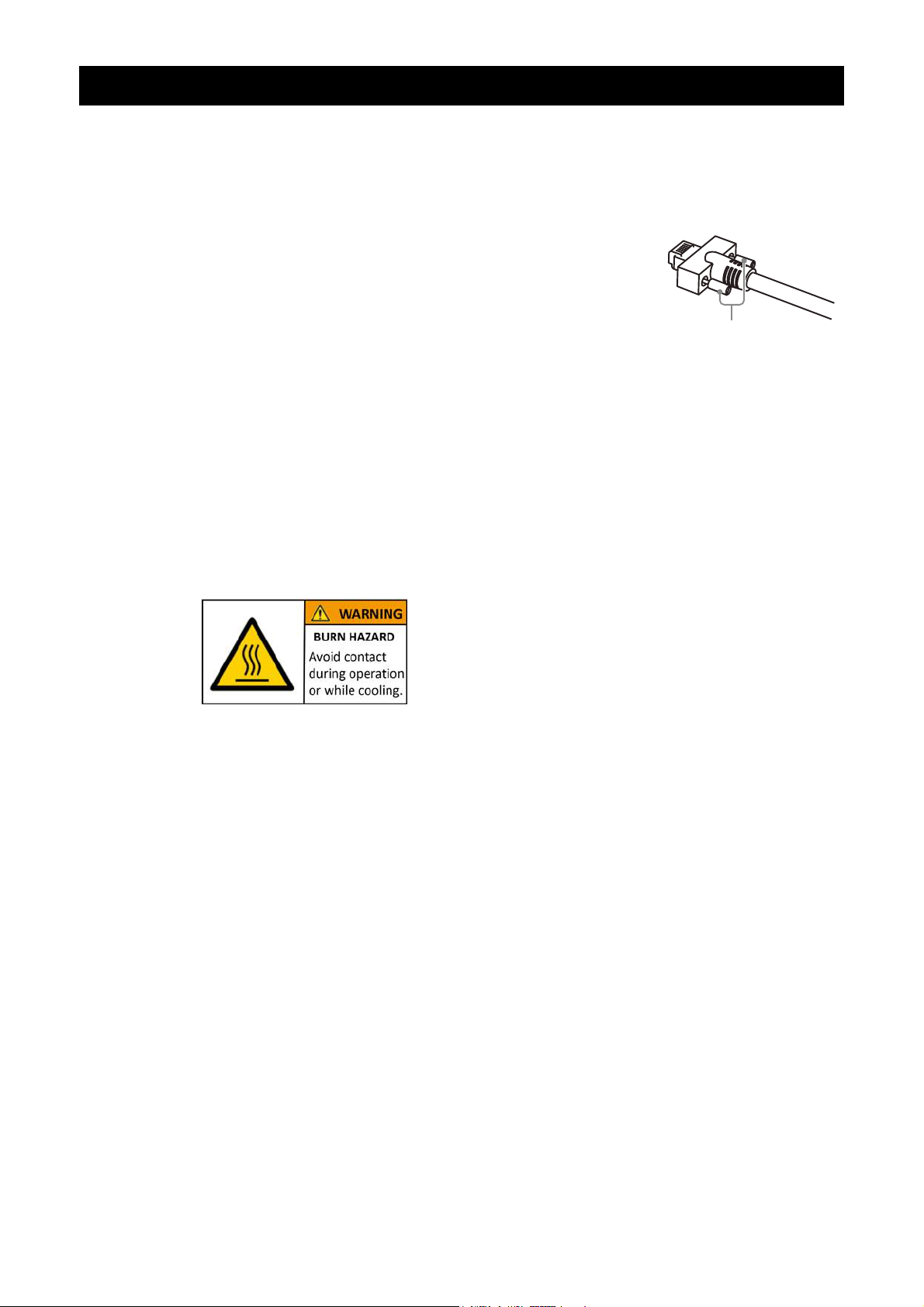
Usage Precautions
Notes on cable configurations
The presence of lighting equipment and television receivers nearby may result in
video noise. In such cases, change the cable configurations or placement.
Notes on LAN cable connection
Secure the locking screws on the connector manually,
and do not use a driver. Do not secure the screws too
tightly. Doing so may wear down the screw threads
on the camera. (Tightening torque: 0.147 Nm or less)
Notes on temperature conditions
The guaranteed operating temperature and humidity of this camera are
-5℃ to +45℃, 20% to 80% (non-condensing).
Please make sure the following temperature condition is met when operating
the unit.
1) The camera's internal temperature sensor detects temperatures of 101 °C
or less during operation.
If the above temperature conditions are exceeded, take measures to dissipate
heat according to your installation environment and conditions.
SW-4000Q-10GE
Secure manually.
Do not secure too tightly.
Notes on attaching the lens
Avoiding dust particles
When attaching the lens to the camera, stray dust and other particles may adhere
to the sensor surface and rear surface of the lens. Be careful of the following
when attaching the lens.
• Work in a clean environment.
• Do not remove the caps from the camera and lens until immediately before
you attach the lens.
• To prevent dust from adhering to surfaces, point the camera and lens
downward and do not allow the lens surface to come into contact with your
hands or other objects.
• Always use a blower brush to remove any dust that adheres.
Never use your hands or cloth, blow with your mouth, or use other methods to
remove dust.
Depending on the operating environment,
the surface of the camera may become very hot
during operation.
Do not touch the camera during operation and
while it is being cooled.
Also, make sure that the cable surface and other
easily deformable items do not contact the surface
of the camera.
— 5 —

Phenomena specific to CMOS image sensors
The following phenomena are known to occur on cameras equipped with CMOS
image sensors. These do not indicate malfunctions.
• Aliasing
When shooting straight lines, stripes, and similar patterns, vertical aliasing
(zigzag distortion) may appear on the monitor.
• Blooming
When strong light enters the camera, some pixels on the CMOS image sensor
may receive much more light than they are designed to hold, causing the
accumulated signal charge to overflow into surrounding pixels.This
“blooming” phenomenon can be seen in the image, but does not affect the
operation of the camera.
• Fixed pattern noise
When shooting dark objects in high-temperature conditions, fixed pattern noise
may occur throughout the entire video monitor screen.
• Defective pixels
Defective pixels (white and black pixels) of the CMOS image sensor are
minimized at the factory according to shipping standards. However, as this
phenomenon can be affected by the ambient temperature, camera settings
(e.g., high sensitivity and long exposure), and other factors, be sure to operate
within the camera’s specified operating environment.
SW-4000Q-10GE
Notes on exportation
When exporting this product, please follow the export regulations of your country
or region.
— 6 —
SW-4000Q-10GE
Features
The SW-4000Q-10GE is a 4CMOS line scan camera using four 4096 pixel line sensors
mounted on a prism, for the R, G, B and NIR channels.
The camera outputs digital data in single-stream or dual-stream via 10 GigE interface.
Features overview
• Prism technology for superior color quality and better color differentiation.
• Pixel size can be switched (
• Supports vertical dual-line binning, 2x horizontal binning, or both.
• It can output both video in visible region and video in the near-infrared region.
Supports Pixel Format RGBa8, which outputs video in the visible region and video
in the near-infrared region as single-stream.
Video in the visible region (RGB8, RGB10V1Packed, RGB10p32, YUV422) and video
in the near-infrared region (Mono8, Mono10Packed) can be output as dual-stream.
• High-speed scanning (Maximum line rate)
Pixel Format RGBa8(8bit) : 73 kHz
Pixel Format YUV422(8bit) + Mono8(8bit) : 74 kHz
Pixel Format RGB8(8bit) + Mono8(8bit) : 72 kHz
• HSI, sRGB, Adobe RGB and XYZ color space conversion.
• Support for connection of rotary encoders.
• Excellent shock and vibration resistance.
• GenICam compliant.
7.5 µm x 7.5 µm, 7.5 µm x 10.5 µm)
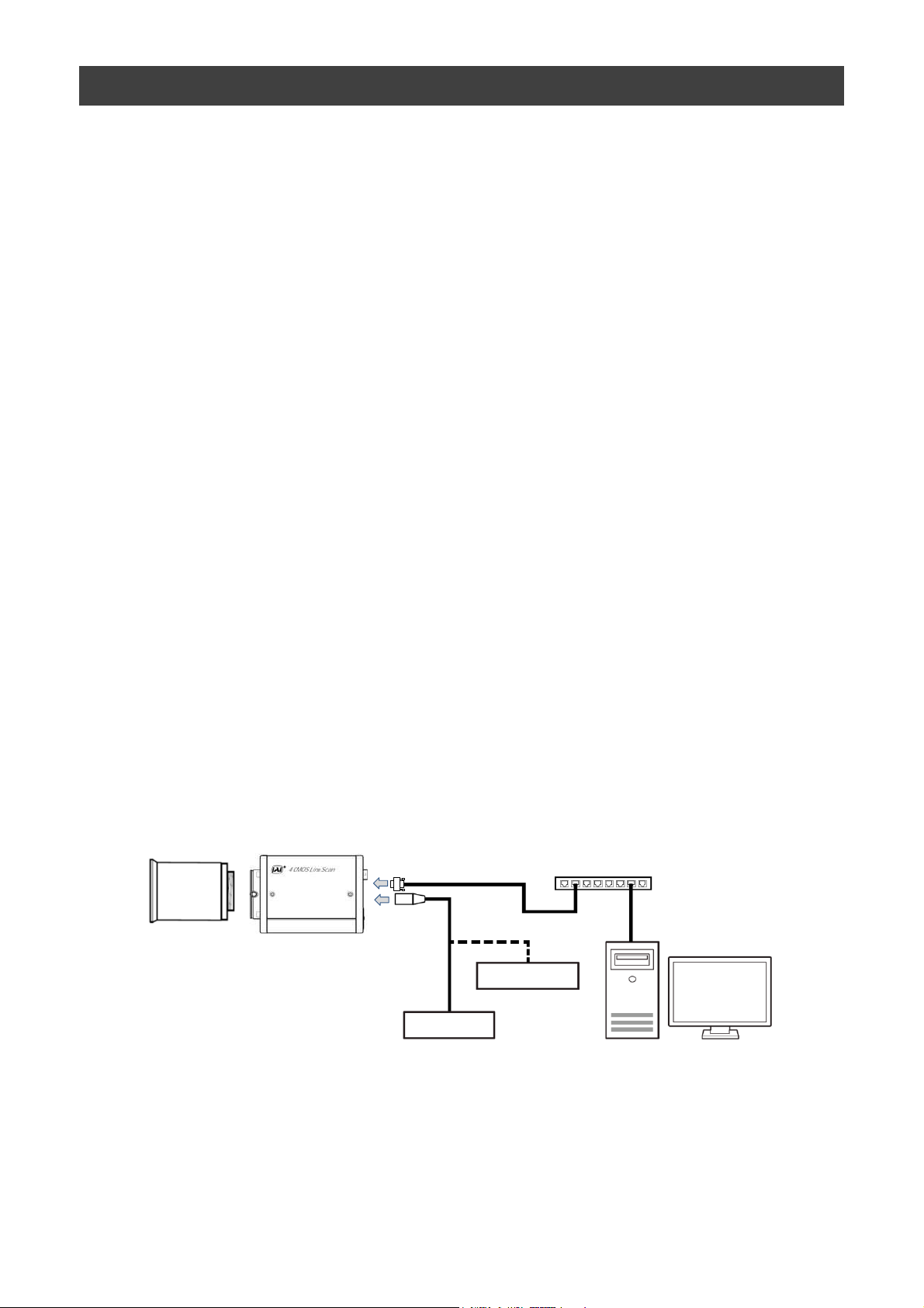
Connection example:
Lens
Camera
Switching hub
AC adapter
External Trigger
PC
— 7 —
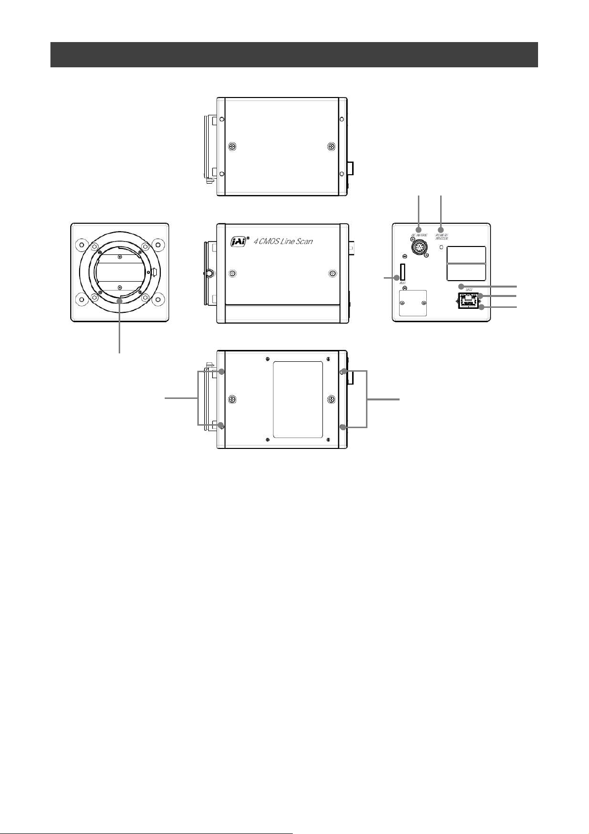
Parts Identification
⑥
SW-4000Q-10GE
②
⑦
①
⑧
⑧
① Lens mount (M52-mount /F-mount)
Mount a M52-mount lens, F-mount lens, etc. here.
❖ Before mounting a lens, be sure to refer to “Step 2:Connecting Devices” and confirm
the precautions for attaching a lens and the supported lens types.
⑤
④
③
— 8 —
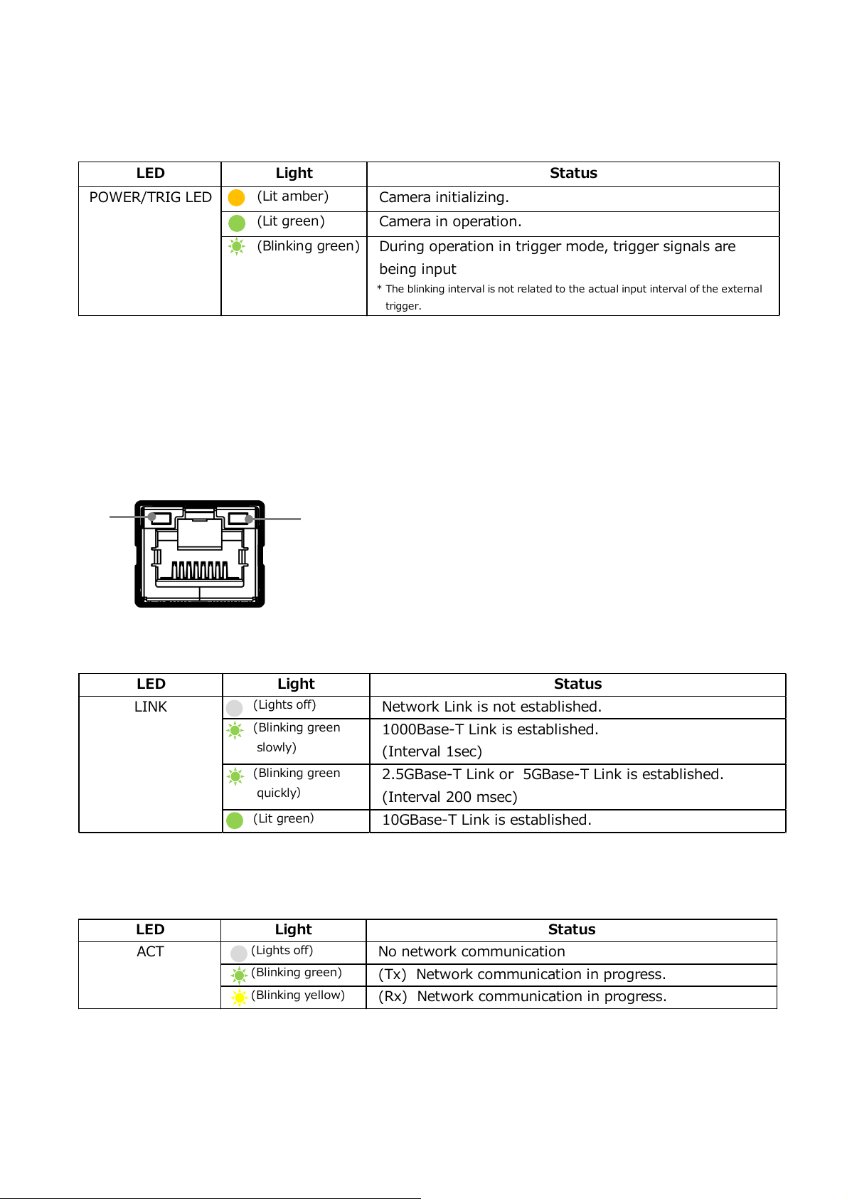
LED Light Status
(Lights off)
No network communication
(Blinking green)
(Tx) Network communication in progress.
(Blinking yellow)
(Rx) Network communication in progress.
ACT
LED Light Status
(Lights off)
Network Link is not established.
(Blinking green
slowly)
1000Base-T Link is established.
(Interval 1sec)
(Blinking green
quickly)
2.5GBase-T Link or 5GBase-T Link is established.
(Interval 200 msec)
(Lit green)
10GBase-T Link is established.
LINK
LED Light
Status
(Lit amber)
Camera initializing.
(Lit green)
Camera in operation.
(Blinking green)
During operation in trigger mode, trigger signals are
being input
* The blinking interval is not related to the actual input interval of the external
trigger.
POWER/TRIG LED
SW-4000Q-10GE
② POWER/TRIG LED
Indicates the power and trigger input status.
LED status and camera status
③ RJ-45 connector
The camera supports the following Ethernet standards.
(1000Base-T, 2.5GBase-T, 5GBase-T, 10GBase-T)
Depending on the Ethernet standard to be used, the cable type and the maximum cable
length are limited.
For details, refer to "Step 2 Connecting Devices".
⑤
④
④ LINK LED
Indicates the link status of the network.
⑤ ACT LED
Indicates the network communication status.
— 9 —
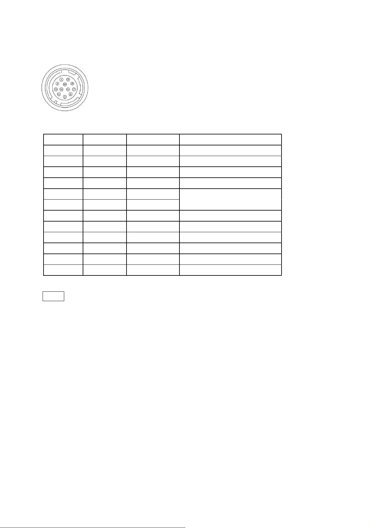
Pin No.
Input/Output
Signal Description
1 GND
2 Power In DC In DC 10 V ~ 25 V
3 GND
4 RESERVED
5 In Opto In 1 -
6 In Opto In 1 +
7 Out TTL Out 4 Line 12
8 NC
9 Out TTL Out 1 Line 1
10 In TTL In 1 Line 4
11 Power In DC In DC 10 V ~ 25 V
12 GND
Line 5
⑥ DC IN/TRIG connector(12-pin round)
Connect the cable for a power supply (optional) or for DC IN / trigger IN here.
HR10A-10R-12PB(71)(Hirose Electric or equivalent )
SW-4000Q-10GE
Note
In order to operate at the maximum line rate, 10-25V DC power must be connected to
both Pin1/Pin2 and Pin 11/Pin12. If you supply power to only one pin pair, the camera
may operate at less than the maximum line rate or may not operate at all.
IMPORTANT! You must supply the same voltage to each pin pair. If you supply different
voltages to each pin pair, the power unit of the camera will be damaged.
TTL signal specification
TTL out signal specification (Typ.)
Output voltage: Low 0.0V
Input/Output current: +/-32mA
TTL in signal specification (Typ.)
Input voltage: Low 0.0~0.8V
High 5.0V
High 2.0~5.5V
— 10 —

Pin No.
Input/Output
Signal Description
1 Out TTL_OUT2 Line 8
2 Out TTL_OUT3 Line 9
3 In TTL_IN2 Line 10
4 N.C.
5 GND GND
6 In TTL_IN3 Line 13
7 N.C.
8 N.C.
9 GND GND
10 GND GND
Recommended external input circuit diagram (reference example)
SW-4000Q-10GE
User side
User
side
⑦ AUX connector(10-pin)
JAI Camera side
CAMERA
side
Camera side:3260-10S3(55)(Hirose Electric or equivalent )
Cable side :3240-10P-C(50)(Hirose Electric or equivalent )
⑧ Camera locking screw holes (M4, 6mm depth)
Use these holes when mounting the camera directly to a wall or other structural
system.
— 11 —
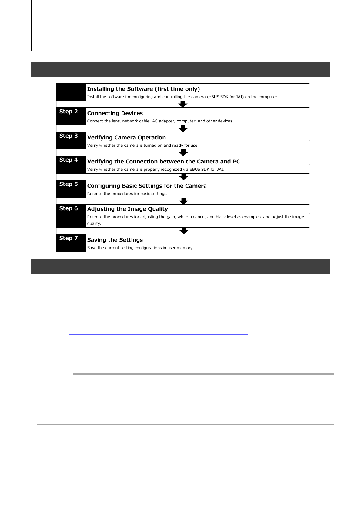
Step 7
Saving the Settings
Save the c urrent setting configurations in user memory.
Step 3
Verifying Camera Operation
Verify whe the r the c ame ra is turne d o n and re ad y for use .
Step 4
Verifying the Connection between the Camera and PC
Verify whe the r the c ame ra is properly re co gnize d via eB US SDK for J AI.
Step 5
Configuring Basic Settings for the Camera
Refer to the pro ce dures fo r basic se ttings.
Installing the Software (first time only)
Install the software for configuring and controlling the camera (eBUS SDK for JAI) on the c omputer.
Step 1
Step 2
Connecting Devices
Connect the lens, network cable, AC adapter, computer, and other devices.
Step 6
Adjusting the Image Quality
Refer to the procedures for adjusting the gain, white balance, and black level as examples, and adjust the image
quality.
Preparation
Preparation Process
SW-4000Q-10GE
Step 1: Installing the Software (first time only)
When using the camera for the first time, install the software for configuring and
controlling the camera (eBUS SDK for JAI) on the computer.
❖ When you install eBUS SDK for JAI, eBUS SDK for JAI player will also be installed.
Download the eBUS SDK for JAI from the JAI website.
1
URL https://www.jai.com/jp/support-software/jai-software
Install eBUS SDK for JAI on the computer.
2
Caution
eBUS SDK for JAI was released in April 2018 and is the latest software for setting and
controlling JAI cameras.
When JAI SDK and eBUS SDK for JAI are installed on the same machine, conflicts can
occur. Therefore, JAI strongly recommends that JAI SDK is uninstalled before installing
eBUS SDK for JAI.
— 12 —
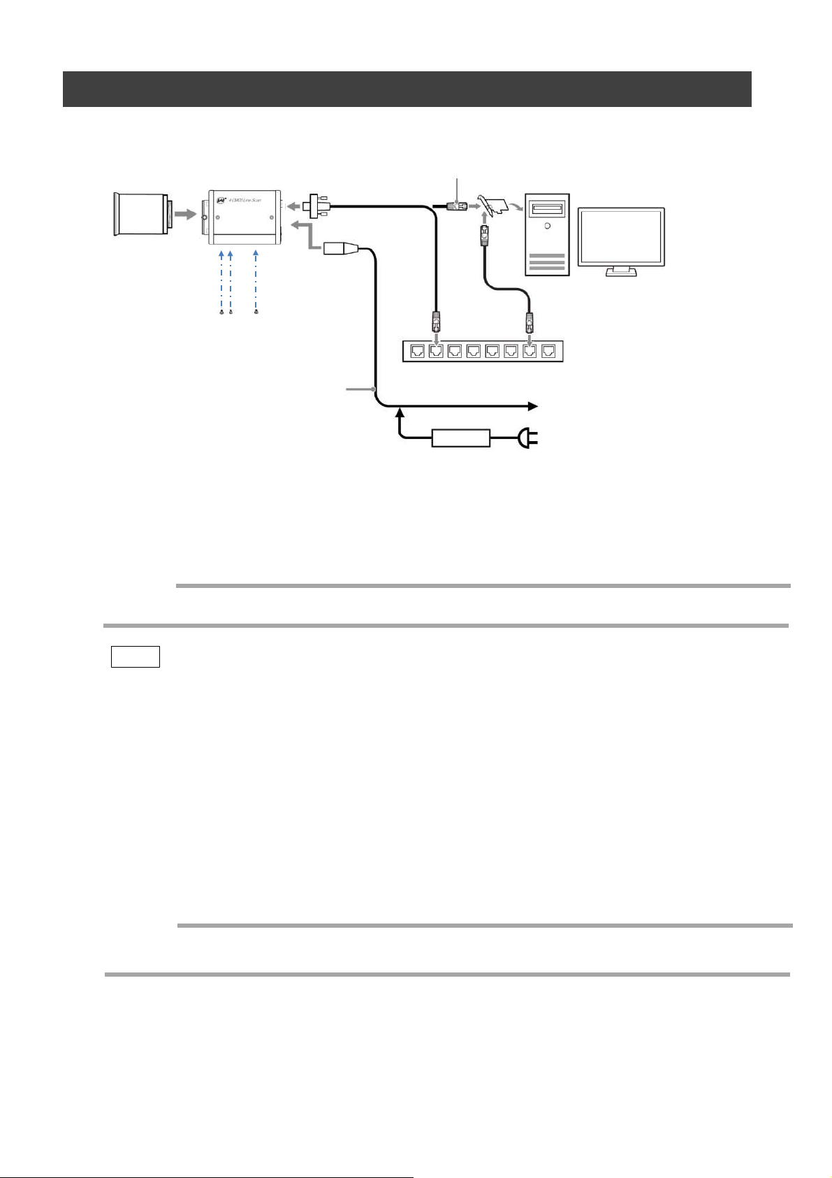
Step 2: Connecting Devices
SW-4000Q-10GE
Camera body
③ LAN cable
①Lens
② Direct connection
⑤ DC IN/trigger IN
connection cable
① Lens
・Attach an M52-mount lens or F-mount lens.
(or direct connection)
④ Network card
Switching hub
or
⑥ AC adapter (not supplied)
Caution
The maximum performance of the camera may not be realized depending on the lens.
Note
The following formula can be used to estimate the focal length.
focal length = WD/(1 + W/w)
WD: Working distance (distance between lens and object)
W : Width of object
w : Width of sensor 30.72 mm on this camera.
② Direct connection
When mounting the camera directly to another device, for example, use screws that match the
camera locking screw holes on the camera. (M4, 6 mm depth)
Caution
For heavy lenses, be sure to support the lens itself. Do not use configurations in which its weight
is supported by the camera.
— 13 —
Cat5e Cat6/Cat6e Cat6A Cat7
1000Base-T 100m 100m 100m 100m
2.5GBase-T 100m 100m 100m 100m
5GBase-T 100m 100m 100m
10GBase-T 55m 100m 100m
SW-4000Q-10GE
③ LAN cable
Connect a LAN cable to the RJ-45 connector.
・ The camera supports the following Ethernet standards.
(1000Base-T, 2.5GBase-T, 5GBase-T, 10GBase-T)
・ The longest cable length varies depending on the type of LAN cable and the Ethernet standard.
Below, the table shows the relationship diagram between LAN cable type and Ethernet standard.
Correctly select the LAN cable type according to the Ethernet standard to be used.
■ About the longest cable length
LAN cable type
Ethernet standard
-
-
・ Refer to the specifications of the cable for details on its bend radius.
Caution
Secure the locking screws on the connector
manually, and do not use a driver. Do not secure
the screws too tightly. Doing so may wear down the
screw threads on the camera. (Tightening torque:
0.147 Nm or less)
Secure manually.
Do not secure too tightly.
④ Network card
Install this in the computer that will be used to configure and operate the camera.
Refer to the instruction manual of the network card, and configure settings on the computer as
necessary.
— 14 —
⑤ DC IN / trigger IN connection cable
⑥ AC adapter (power supply) (if necessary)
Connect the AC adapter and the round connector of the connection cable to the DC IN /
trigger IN connector on the camera.
Step 3: Verifying Camera Operation
When power is supplied to the camera while the necessary equipment is connected, the
POWER/TRIG LED at the rear of the camera lights amber, and initialization of the camera
starts. When initialization is complete, the POWER/TRIG LED lights green.
Verify whether power is being supplied to the camera by checking the rear LED.
When properly turned on
Lit green
SW-4000Q-10GE
* For details on how to read the LEDs, see “LED status and camera status” in the “Parts
Identification” section.
Step 4: Verifying the Connection between the Camera and PC
Verify whether the camera is properly recognized via Control Tool.
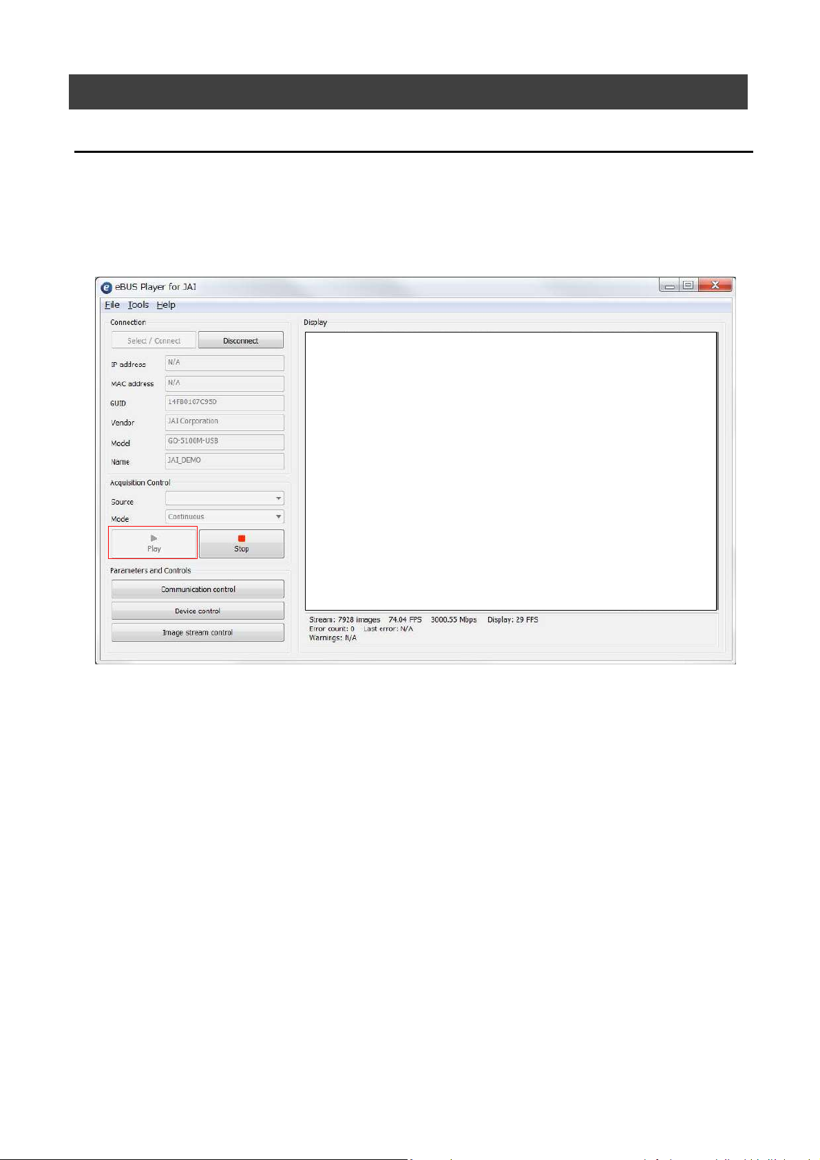
Connecting the Camera to Control Tool
Startup eBUS Player for JAI
1
eBUS Player for JAI startup screen appears.
— 15 —
SW-4000Q-10GE
Select the camera you want to configure.
2
Push Select / Connect button
The connected camera is listed.
Please select one camera.
— 16 —
SW-4000Q-10GE
3
Check that the settings of the selected camera are displayed.
Push the Device control button.
The screen shown below will be displayed. In this window you can adjust various
settings of the camera.
This completes the procedure for verifying whether the camera is properly recognized and
whether control and settings configuration are possible.
— 17 —

Item Setting value / selectable range
Trigger Mode On
Trigger Selector Line Start
Trigger Source Any
Trigger Activation
LevelHigh
(high-level duratio n)
,
LevelLow
(low -le vel duratio n)
Exposure Mode TriggerWidth
(co ntro l via trig ger width)
Item Setting value / selectable range
Trigger Mode On
Trigger Selector Line Start
Trigger Source Any
Trigger Activation
Rising Edge
(rising e dge of input signal)
,
Falling Edge
(falling edge of input signal)
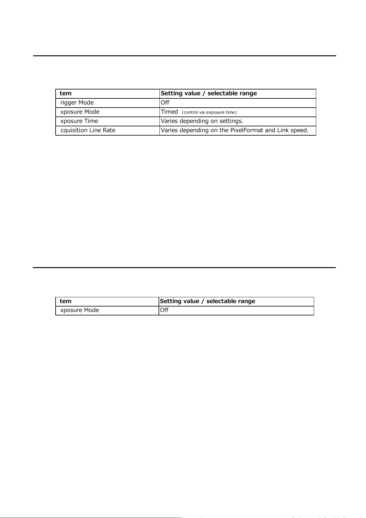
Exposure Mode Timed
(control via exposure time)
Exposure Time Varies depending on settings.
Step 5 Configuring Basic Settings for the Camera
■Control via External Triggers
When Controlling the Exposure Time Using Specified Exposure Times
Configure the settings as follows.
SW-4000Q-10GE
Set [Exposure Mode] to [Timed].
1
Specify the exposure time in [Exposure Time].
2
Set [Trigger Mode] to [On] and set [Trigger Selector] to [Line Start].
3
If necessary, change the [Trigger Source], and [Trigger Activation] settings.
4
When Controlling the Exposure Time Using the Pulse Width of the Trigger
Input Signal
Configure the settings as follows.
Set [Trigger Mode] to [On] .
1
Set [Exposure Mode] to [Trigger Width] .
2
If necessary, change the [Trigger Source] and [Trigger Activation] settings.
3
— 18 —
Item Setting value / selectable range
Exposure Mode Off
Item
Setting value / selectable range
Trigger Mode Off
Exposure Mode Timed
(control via exposure time)
Exposure Time Varies depending on settings.
Acquisition Line Rate Varies depending on the PixelFormat and Link speed.
■Control Without External Triggers
When Controlling the Exposure Time Using Specified Exposure Times
Configure the settings as follows.
Set [Exposure Mode] to [Timed].
1
SW-4000Q-10GE
Set [Trigger Mode] to [Off].
2
Specify a line period slower than the exposure time in [Acquisition Line Rate].
3
Specify the exposure time in [Exposure Time].
4
When Not Controlling the Exposure Time
Configure the settings as follows.
The exposure will be performed with an exposure time equal to 1 / line rate.
* The exposure time specified in [Exposure Time] will be disabled.
— 19 —
Step 6: Adjusting the Image Quality
Display the camera image and adjust the image quality.
Displaying the Image
Display the image captured by the camera.
When you push [Play] button, the camera image appears in right area.
*) By default settings, the video in the visible region are displayed.
SW-4000Q-10GE
To maximize the performance of the camera, configure its basic function in the following
order.
Configure the line rate.
1
◇ For details on this setting, “Variable Line Rate”.
Configure the exposure time.
2
◇ For details on this setting, “Electronic Shutter” .
Perform DSNU correction.
3
◇ For details on this setting, “Pixel Sensitivity Correction”.
Perform PRNU correction.
4
◇ For details on this setting, “Pixel Sensitivity Correction” .
Adjust the black level.
5
◇ For details on this setting, “Black Level Correction”.
— 20 —

Adjust the white balance.
6
Adjust the white balance using the automatic adjustment function.
① Place a white sheet of paper or similar object under the same lighting conditions as
the intended subject, and zoom in to capture the white.
White objects near the subject, such as a white cloth or wall, can also be used.
Be sure to prevent the high-intensity spot lights from entering the screen.
The white balance is automatically adjusted.
② Select the [Balance White Auto] tab, and select [Once].
The white balance is automatically adjusted.
Step 7: Saving the Settings
The setting values configured in the player (eBUS SDK for JAI) will be deleted when the
camera is turned off. By saving current setting values to user memory, you can load and
recall them whenever necessary. You can save up to three sets of user settings in the
camera. (User Set1 to 3)
SW-4000Q-10GE
Memory(Flash)
DefaultSet
UserSet1
UserSet2
UserSet3
一時メモリ
Memory(RAM)
Working Set
Note
Changes to settings are not saved to the computer (eBUS SDK for JAI).
■ To save user settings
eBUS SDK for
JAI (Player)
Stop image acquisition.
1
Expand [UserSetControl], and select the save destination ([UserSet1] to
2
[UserSet3]) in [UserSetSelector].
Note
The factory default setting values are stored in [Default] and cannot be overwritten.
Caution
Settings can only be saved when image acquisition on the camera is stopped.
— 21 —
 Loading...