


User Manual
SW-4000Q-10GE
4CMOS Prism Linescan Camera
Document Version: 1.0
SW-4000Q-10GE_Ver.1.0 _Apr.2019
Thank you for purchasing this product.
Be sure to read this manual before use.
This manual includes important safety precautions and instructions on how to operate the unit. Be sure to read
this manual to ensure proper operation.
The contents of this manual are subject to change without notice for the purpose of improvement.
© 2019 JAI

Contents
36
36
37
38
40
40
41
42
42
43
43
44
45
46
46
58
58
59
61
62
64
65
66
67
SW-4000Q-10GE
Notice/Warranty/Certifications
Usage Precautions
Features
Parts Identifications
Preparation
Preparation Process
Step 1:Installing the Software
Step 2:Connecting Devices
Step 3:Verifying Camera Operation
Step 4:Verifying the Connection between
the Camera and PC
Step 5:Changing the Camera Settings
Step 6:Adjusting the Image Quality
Step 7:Saving the Settings
Main Functions
Valid Input / Output Combinations
GPIO(Digital Input/Output Settings)
Pixel Format
ExposureMode
Image Output Timing
Pixel Sensitivity Correction
Gain Control
Lookup Table (LUT)
Gamma Function
ShadingCorrection
Black Level Correction
Variable Line Rate
Electronic Shutter
12
12
12
13
15
15
18
20
21
23
23
24
25
27
27
31
32
33
34
35
35
36
36
3
5
7
8
EEN (Exposure Enable) Function
Test Pattern Function
Color Space Conversion
Counter And Timer Control Function
Chromatic Aberration Correction
Connecting Rotary Encoders
Frame Start Trigger
Binning Function
ROI (Regional Scanning Function)
Chunk Data Function
Delayed Readout
Event Control Function
Action Control Function
Setting List
Feature Properties
Miscellaneous
Troubleshooting
Specifications
Spectral Response
Dimensions
Comparison of the Decibel Display and
Multiplier Display
User’s Record
Index
Revision history
— 2 —
SW-4000Q-10GE
Notice
The material contained in this manual consists of information that is proprietary to JAI Ltd., Japan and may only
be used by the purchasers of the product. JAI Ltd., Japan makes no warranty for the use of its product and
assumes no responsibility for any errors which may appear or for damages resulting from the use of the
information contained herein. JAI Ltd., Japan reserves the right to make changes without notice.
Company and product names mentioned in this manual are trademarks or registered trademarks of their
respective owners.
Warranty
For information about the warranty, please contact your factory representative.
Certifications
CE compliance
As defined by the Directive 2004/108/EC of the European Parliament and of the Council, EMC (Electromagnetic
compatibility), JAI Ltd., Japan declares that SW-4000Q-10GE complies with the following provisions applying to
its standards.
EN 61000-6-3 (Generic emission standard part 1)
EN 61000-6-2 (Generic immunity standard part 1)
FCC
This equipment has been tested and found to comply with the limits for a Class B digital device, pursuant to Part
15 of the FCC Rules. These limits are designed to provide reasonable protection against harmful interference in
a residential installation. This equipment generates, uses and can radiate radio frequency energy and, if not
installed and used in accordance with the instructions, may cause harmful interference to radio communications.
However, there is no guarantee that interference will not occur in a particular installation. If this equipment
does cause harmful interference to radio or television reception, which can be determined by turning the
equipment off and on, the user is encouraged to try to correct the interference by one or more of the following
measures:
• Reorient or relocate the receiving antenna.
• Increase the separation between the equipment and receiver.
• Connect the equipment into an outlet on a circuit different from that to which the
receiver is connected.
• Consult the dealer or an experienced radio/TV technician for help.
Warning
Changes or modifications to this unit not expressly approved by the party responsible for FCC compliance could
void the user’s authority to operate the equipment.
KC
— 3 —
SW-4000Q-10GE
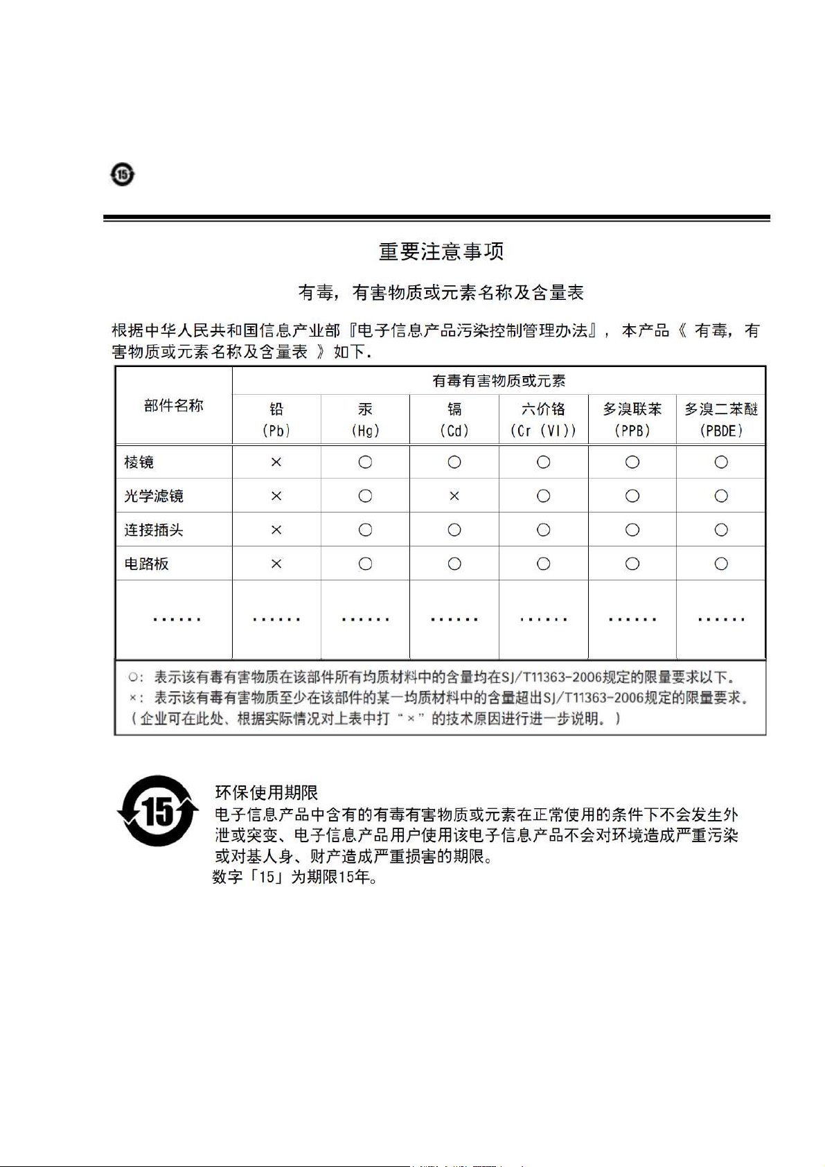
Supplement
The following statement is related to the regulation on “ Measures for the Administration
of the control of Pollution by Electronic Information Products “ , known as “ China RoHS “.
The table shows contained Hazardous Substances in this camera.
mark shows that the environment-friendly use period of contained Hazardous
Substances is 15 years.
— 4 —
Usage Precautions
Notes on cable configurations
The presence of lighting equipment and television receivers nearby may result in
video noise. In such cases, change the cable configurations or placement.
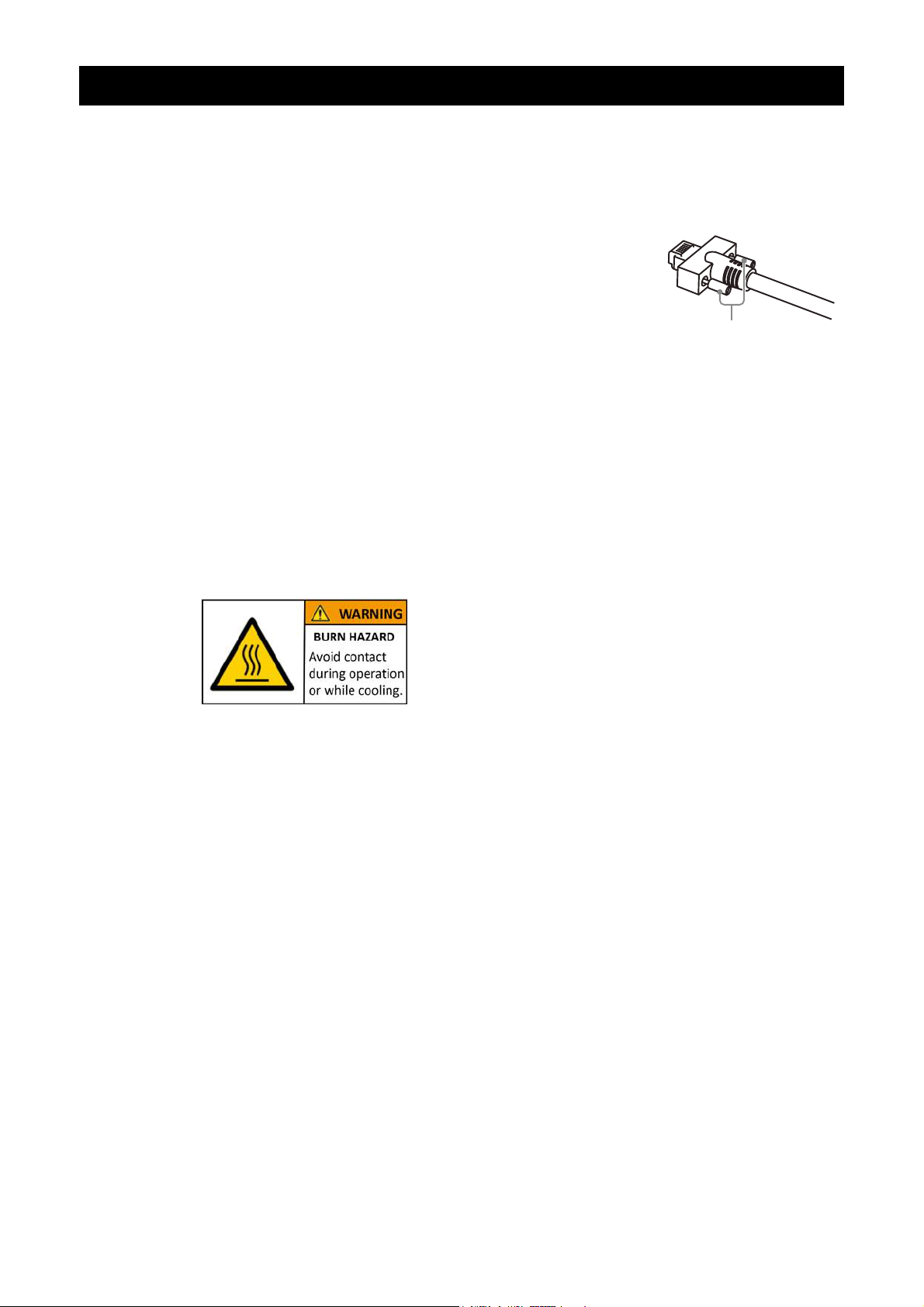
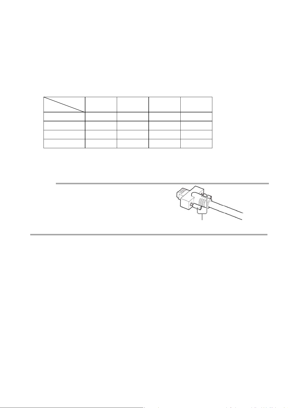
Notes on LAN cable connection
Secure the locking screws on the connector manually,
and do not use a driver. Do not secure the screws too
tightly. Doing so may wear down the screw threads
on the camera. (Tightening torque: 0.147 Nm or less)
Notes on temperature conditions
The guaranteed operating temperature and humidity of this camera are
-5℃ to +45℃, 20% to 80% (non-condensing).
Please make sure the following temperature condition is met when operating
the unit.
1) The camera's internal temperature sensor detects temperatures of 101 °C
or less during operation.
If the above temperature conditions are exceeded, take measures to dissipate
heat according to your installation environment and conditions.
SW-4000Q-10GE
Secure manually.
Do not secure too tightly.
Notes on attaching the lens
Avoiding dust particles
When attaching the lens to the camera, stray dust and other particles may adhere
to the sensor surface and rear surface of the lens. Be careful of the following
when attaching the lens.
• Work in a clean environment.
• Do not remove the caps from the camera and lens until immediately before
you attach the lens.
• To prevent dust from adhering to surfaces, point the camera and lens
downward and do not allow the lens surface to come into contact with your
hands or other objects.
• Always use a blower brush to remove any dust that adheres.
Never use your hands or cloth, blow with your mouth, or use other methods to
remove dust.
Depending on the operating environment,
the surface of the camera may become very hot
during operation.
Do not touch the camera during operation and
while it is being cooled.
Also, make sure that the cable surface and other
easily deformable items do not contact the surface
of the camera.
— 5 —

Phenomena specific to CMOS image sensors
The following phenomena are known to occur on cameras equipped with CMOS
image sensors. These do not indicate malfunctions.
• Aliasing
When shooting straight lines, stripes, and similar patterns, vertical aliasing
(zigzag distortion) may appear on the monitor.
• Blooming
When strong light enters the camera, some pixels on the CMOS image sensor
may receive much more light than they are designed to hold, causing the
accumulated signal charge to overflow into surrounding pixels.This
“blooming” phenomenon can be seen in the image, but does not affect the
operation of the camera.
• Fixed pattern noise
When shooting dark objects in high-temperature conditions, fixed pattern noise
may occur throughout the entire video monitor screen.
• Defective pixels
Defective pixels (white and black pixels) of the CMOS image sensor are
minimized at the factory according to shipping standards. However, as this
phenomenon can be affected by the ambient temperature, camera settings
(e.g., high sensitivity and long exposure), and other factors, be sure to operate
within the camera’s specified operating environment.
SW-4000Q-10GE
Notes on exportation
When exporting this product, please follow the export regulations of your country
or region.
— 6 —
SW-4000Q-10GE
Features
The SW-4000Q-10GE is a 4CMOS line scan camera using four 4096 pixel line sensors
mounted on a prism, for the R, G, B and NIR channels.
The camera outputs digital data in single-stream or dual-stream via 10 GigE interface.
Features overview
• Prism technology for superior color quality and better color differentiation.
• Pixel size can be switched (
• Supports vertical dual-line binning, 2x horizontal binning, or both.
• It can output both video in visible region and video in the near-infrared region.
Supports Pixel Format RGBa8, which outputs video in the visible region and video
in the near-infrared region as single-stream.
Video in the visible region (RGB8, RGB10V1Packed, RGB10p32, YUV422) and video
in the near-infrared region (Mono8, Mono10Packed) can be output as dual-stream.
• High-speed scanning (Maximum line rate)
Pixel Format RGBa8(8bit) : 73 kHz
Pixel Format YUV422(8bit) + Mono8(8bit) : 74 kHz
Pixel Format RGB8(8bit) + Mono8(8bit) : 72 kHz
• HSI, sRGB, Adobe RGB and XYZ color space conversion.
• Support for connection of rotary encoders.
• Excellent shock and vibration resistance.
• GenICam compliant.
7.5 µm x 7.5 µm, 7.5 µm x 10.5 µm)
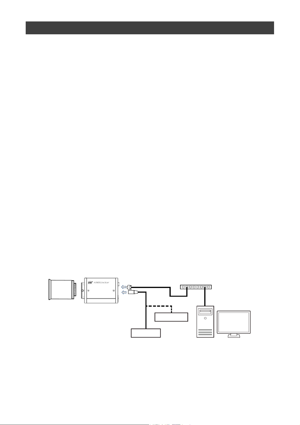
Connection example:
Lens
Camera
Switching hub
AC adapter
External Trigger
PC
— 7 —
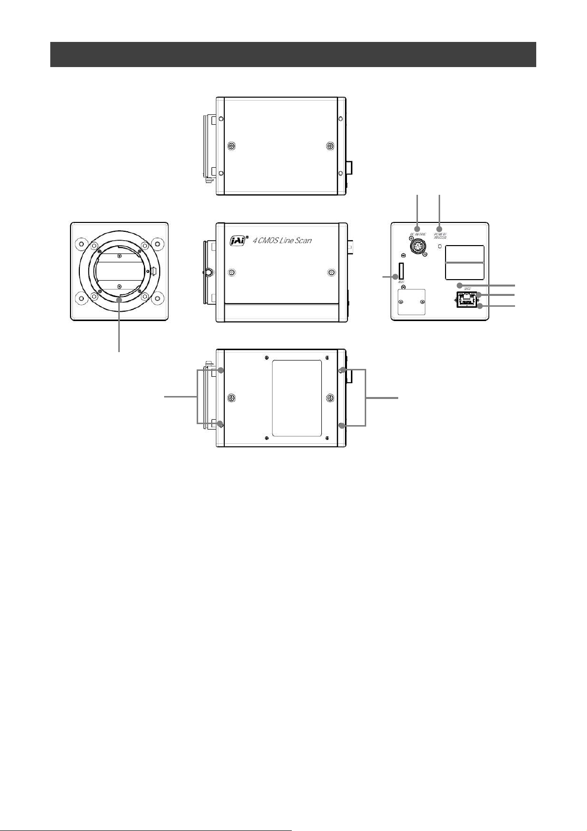
Parts Identification
⑥
SW-4000Q-10GE
②
⑦
①
⑧
⑧
① Lens mount (M52-mount /F-mount)
Mount a M52-mount lens, F-mount lens, etc. here.
❖ Before mounting a lens, be sure to refer to “Step 2:Connecting Devices” and confirm
the precautions for attaching a lens and the supported lens types.
⑤
④
③
— 8 —
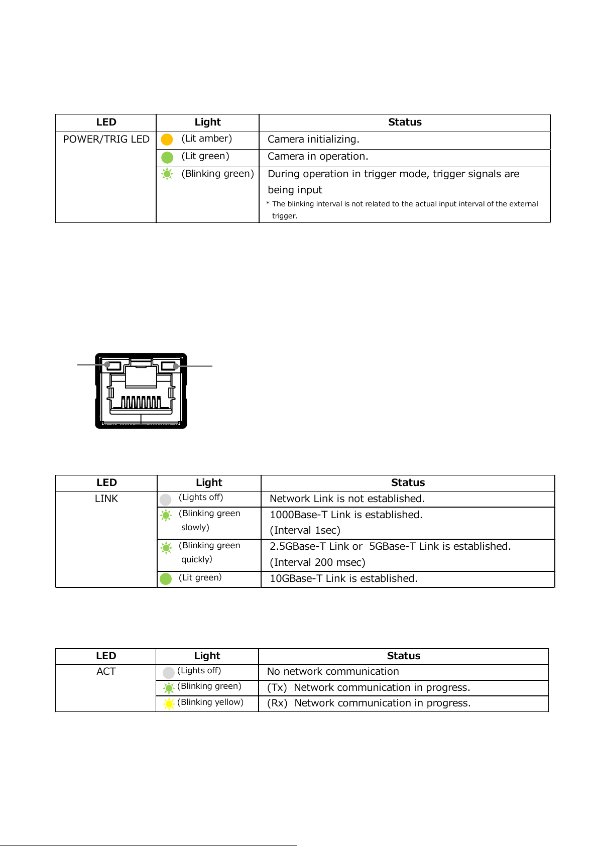
LED Light Status
(Lights off)
No network communication
(Blinking green)
(Tx) Network communication in progress.
(Blinking yellow)
(Rx) Network communication in progress.
ACT
LED Light Status
(Lights off)
Network Link is not established.
(Blinking green
slowly)
1000Base-T Link is established.
(Interval 1sec)
(Blinking green
quickly)
2.5GBase-T Link or 5GBase-T Link is established.
(Interval 200 msec)
(Lit green)
10GBase-T Link is established.
LINK
LED Light
Status
(Lit amber)
Camera initializing.
(Lit green)
Camera in operation.
(Blinking green)
During operation in trigger mode, trigger signals are
being input
* The blinking interval is not related to the actual input interval of the external
trigger.
POWER/TRIG LED
SW-4000Q-10GE
② POWER/TRIG LED
Indicates the power and trigger input status.
LED status and camera status
③ RJ-45 connector
The camera supports the following Ethernet standards.
(1000Base-T, 2.5GBase-T, 5GBase-T, 10GBase-T)
Depending on the Ethernet standard to be used, the cable type and the maximum cable
length are limited.
For details, refer to "Step 2 Connecting Devices".
⑤
④
④ LINK LED
Indicates the link status of the network.
⑤ ACT LED
Indicates the network communication status.
— 9 —

Pin No.
Input/Output
Signal Description
1 GND
2 Power In DC In DC 10 V ~ 25 V
3 GND
4 RESERVED
5 In Opto In 1 -
6 In Opto In 1 +
7 Out TTL Out 4 Line 12
8 NC
9 Out TTL Out 1 Line 1
10 In TTL In 1 Line 4
11 Power In DC In DC 10 V ~ 25 V
12 GND
Line 5
⑥ DC IN/TRIG connector(12-pin round)
Connect the cable for a power supply (optional) or for DC IN / trigger IN here.
HR10A-10R-12PB(71)(Hirose Electric or equivalent )
SW-4000Q-10GE
Note
In order to operate at the maximum line rate, 10-25V DC power must be connected to
both Pin1/Pin2 and Pin 11/Pin12. If you supply power to only one pin pair, the camera
may operate at less than the maximum line rate or may not operate at all.
IMPORTANT! You must supply the same voltage to each pin pair. If you supply different
voltages to each pin pair, the power unit of the camera will be damaged.
TTL signal specification
TTL out signal specification (Typ.)
Output voltage: Low 0.0V
Input/Output current: +/-32mA
TTL in signal specification (Typ.)
Input voltage: Low 0.0~0.8V
High 5.0V
High 2.0~5.5V
— 10 —

Pin No.
Input/Output
Signal Description
1 Out TTL_OUT2 Line 8
2 Out TTL_OUT3 Line 9
3 In TTL_IN2 Line 10
4 N.C.
5 GND GND
6 In TTL_IN3 Line 13
7 N.C.
8 N.C.
9 GND GND
10 GND GND
Recommended external input circuit diagram (reference example)
SW-4000Q-10GE
User side
User
side
⑦ AUX connector(10-pin)
JAI Camera side
CAMERA
side
Camera side:3260-10S3(55)(Hirose Electric or equivalent )
Cable side :3240-10P-C(50)(Hirose Electric or equivalent )
⑧ Camera locking screw holes (M4, 6mm depth)
Use these holes when mounting the camera directly to a wall or other structural
system.
— 11 —
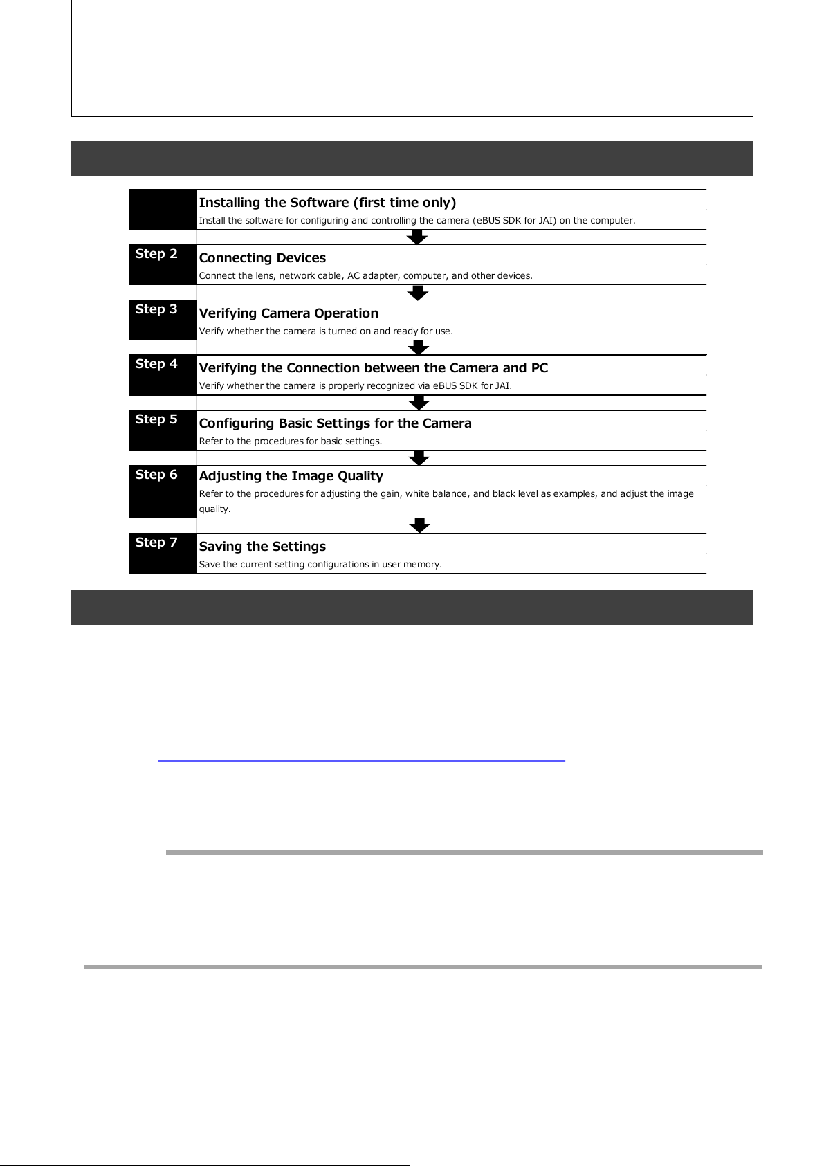
Step 7
Saving the Settings
Save the c urrent setting configurations in user memory.
Step 3
Verifying Camera Operation
Verify whe the r the c ame ra is turne d o n and re ad y for use .
Step 4
Verifying the Connection between the Camera and PC
Verify whe the r the c ame ra is properly re co gnize d via eB US SDK for J AI.
Step 5
Configuring Basic Settings for the Camera
Refer to the pro ce dures fo r basic se ttings.
Installing the Software (first time only)
Install the software for configuring and controlling the camera (eBUS SDK for JAI) on the c omputer.
Step 1
Step 2
Connecting Devices
Connect the lens, network cable, AC adapter, computer, and other devices.
Step 6
Adjusting the Image Quality
Refer to the procedures for adjusting the gain, white balance, and black level as examples, and adjust the image
quality.
Preparation
Preparation Process
SW-4000Q-10GE
Step 1: Installing the Software (first time only)
When using the camera for the first time, install the software for configuring and
controlling the camera (eBUS SDK for JAI) on the computer.
❖ When you install eBUS SDK for JAI, eBUS SDK for JAI player will also be installed.
Download the eBUS SDK for JAI from the JAI website.
1
URL https://www.jai.com/jp/support-software/jai-software
Install eBUS SDK for JAI on the computer.
2
Caution
eBUS SDK for JAI was released in April 2018 and is the latest software for setting and
controlling JAI cameras.
When JAI SDK and eBUS SDK for JAI are installed on the same machine, conflicts can
occur. Therefore, JAI strongly recommends that JAI SDK is uninstalled before installing
eBUS SDK for JAI.
— 12 —
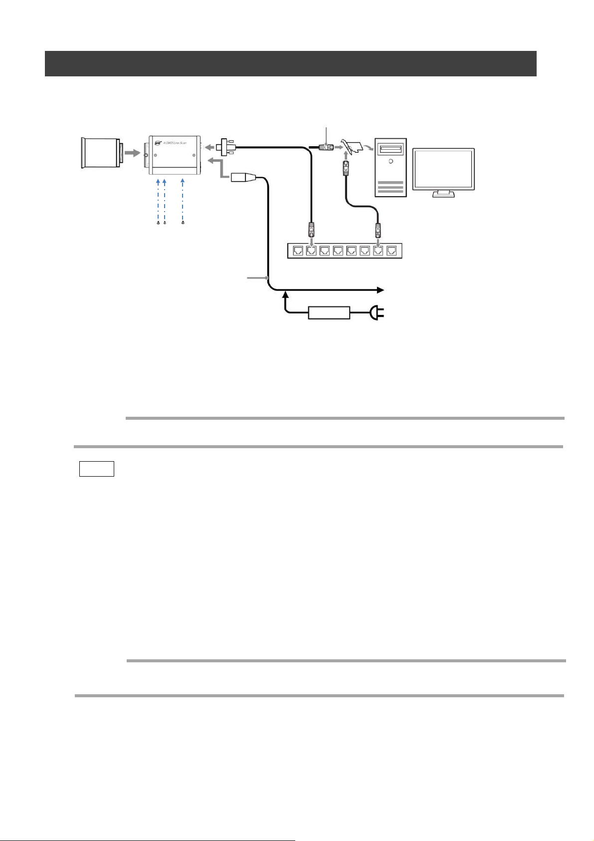
Step 2: Connecting Devices
SW-4000Q-10GE
Camera body
③ LAN cable
①Lens
② Direct connection
⑤ DC IN/trigger IN
connection cable
① Lens
・Attach an M52-mount lens or F-mount lens.
(or direct connection)
④ Network card
Switching hub
or
⑥ AC adapter (not supplied)
Caution
The maximum performance of the camera may not be realized depending on the lens.
Note
The following formula can be used to estimate the focal length.
focal length = WD/(1 + W/w)
WD: Working distance (distance between lens and object)
W : Width of object
w : Width of sensor 30.72 mm on this camera.
② Direct connection
When mounting the camera directly to another device, for example, use screws that match the
camera locking screw holes on the camera. (M4, 6 mm depth)
Caution
For heavy lenses, be sure to support the lens itself. Do not use configurations in which its weight
is supported by the camera.
— 13 —
Cat5e Cat6/Cat6e Cat6A Cat7
1000Base-T 100m 100m 100m 100m
2.5GBase-T 100m 100m 100m 100m
5GBase-T 100m 100m 100m
10GBase-T 55m 100m 100m
SW-4000Q-10GE
③ LAN cable
Connect a LAN cable to the RJ-45 connector.
・ The camera supports the following Ethernet standards.
(1000Base-T, 2.5GBase-T, 5GBase-T, 10GBase-T)
・ The longest cable length varies depending on the type of LAN cable and the Ethernet standard.
Below, the table shows the relationship diagram between LAN cable type and Ethernet standard.
Correctly select the LAN cable type according to the Ethernet standard to be used.
■ About the longest cable length
LAN cable type
Ethernet standard
-
-
・ Refer to the specifications of the cable for details on its bend radius.
Caution
Secure the locking screws on the connector
manually, and do not use a driver. Do not secure
the screws too tightly. Doing so may wear down the
screw threads on the camera. (Tightening torque:
0.147 Nm or less)
Secure manually.
Do not secure too tightly.
④ Network card
Install this in the computer that will be used to configure and operate the camera.
Refer to the instruction manual of the network card, and configure settings on the computer as
necessary.
— 14 —
⑤ DC IN / trigger IN connection cable
⑥ AC adapter (power supply) (if necessary)
Connect the AC adapter and the round connector of the connection cable to the DC IN /
trigger IN connector on the camera.
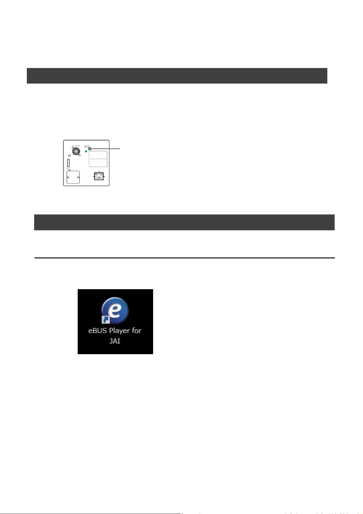
Step 3: Verifying Camera Operation
When power is supplied to the camera while the necessary equipment is connected, the
POWER/TRIG LED at the rear of the camera lights amber, and initialization of the camera
starts. When initialization is complete, the POWER/TRIG LED lights green.
Verify whether power is being supplied to the camera by checking the rear LED.
When properly turned on
Lit green
SW-4000Q-10GE
* For details on how to read the LEDs, see “LED status and camera status” in the “Parts
Identification” section.
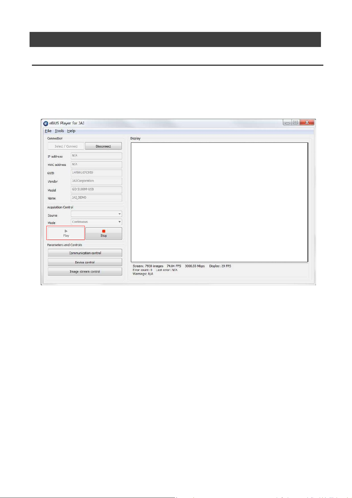
Step 4: Verifying the Connection between the Camera and PC
Verify whether the camera is properly recognized via Control Tool.
Connecting the Camera to Control Tool
Startup eBUS Player for JAI
1
eBUS Player for JAI startup screen appears.
— 15 —
SW-4000Q-10GE
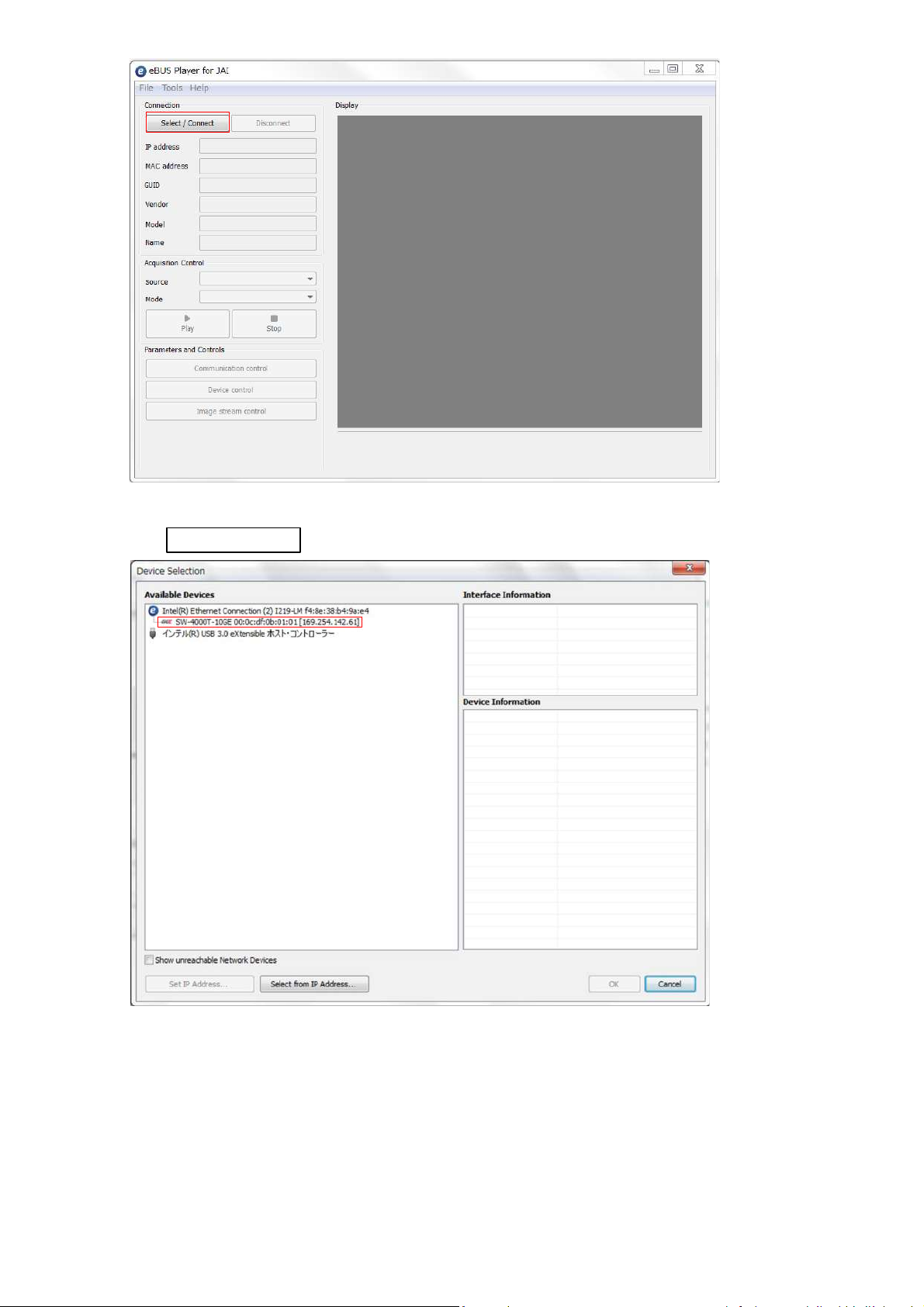
Select the camera you want to configure.
2
Push Select / Connect button
The connected camera is listed.
Please select one camera.
— 16 —
SW-4000Q-10GE
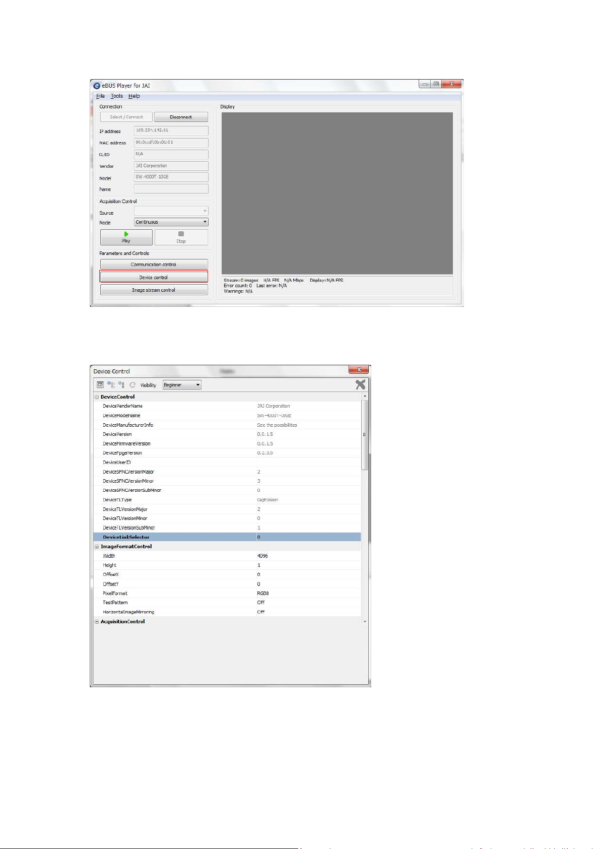
3
Check that the settings of the selected camera are displayed.
Push the Device control button.
The screen shown below will be displayed. In this window you can adjust various
settings of the camera.
This completes the procedure for verifying whether the camera is properly recognized and
whether control and settings configuration are possible.
— 17 —

Item Setting value / selectable range
Trigger Mode On
Trigger Selector Line Start
Trigger Source Any
Trigger Activation
LevelHigh
(high-level duratio n)
,
LevelLow
(low -le vel duratio n)
Exposure Mode TriggerWidth
(co ntro l via trig ger width)
Item Setting value / selectable range
Trigger Mode On
Trigger Selector Line Start
Trigger Source Any
Trigger Activation
Rising Edge
(rising e dge of input signal)
,
Falling Edge
(falling edge of input signal)
Exposure Mode Timed
(control via exposure time)
Exposure Time Varies depending on settings.
Step 5 Configuring Basic Settings for the Camera
■Control via External Triggers
When Controlling the Exposure Time Using Specified Exposure Times
Configure the settings as follows.
SW-4000Q-10GE
Set [Exposure Mode] to [Timed].
1
Specify the exposure time in [Exposure Time].
2
Set [Trigger Mode] to [On] and set [Trigger Selector] to [Line Start].
3
If necessary, change the [Trigger Source], and [Trigger Activation] settings.
4
When Controlling the Exposure Time Using the Pulse Width of the Trigger
Input Signal
Configure the settings as follows.
Set [Trigger Mode] to [On] .
1
Set [Exposure Mode] to [Trigger Width] .
2
If necessary, change the [Trigger Source] and [Trigger Activation] settings.
3
— 18 —
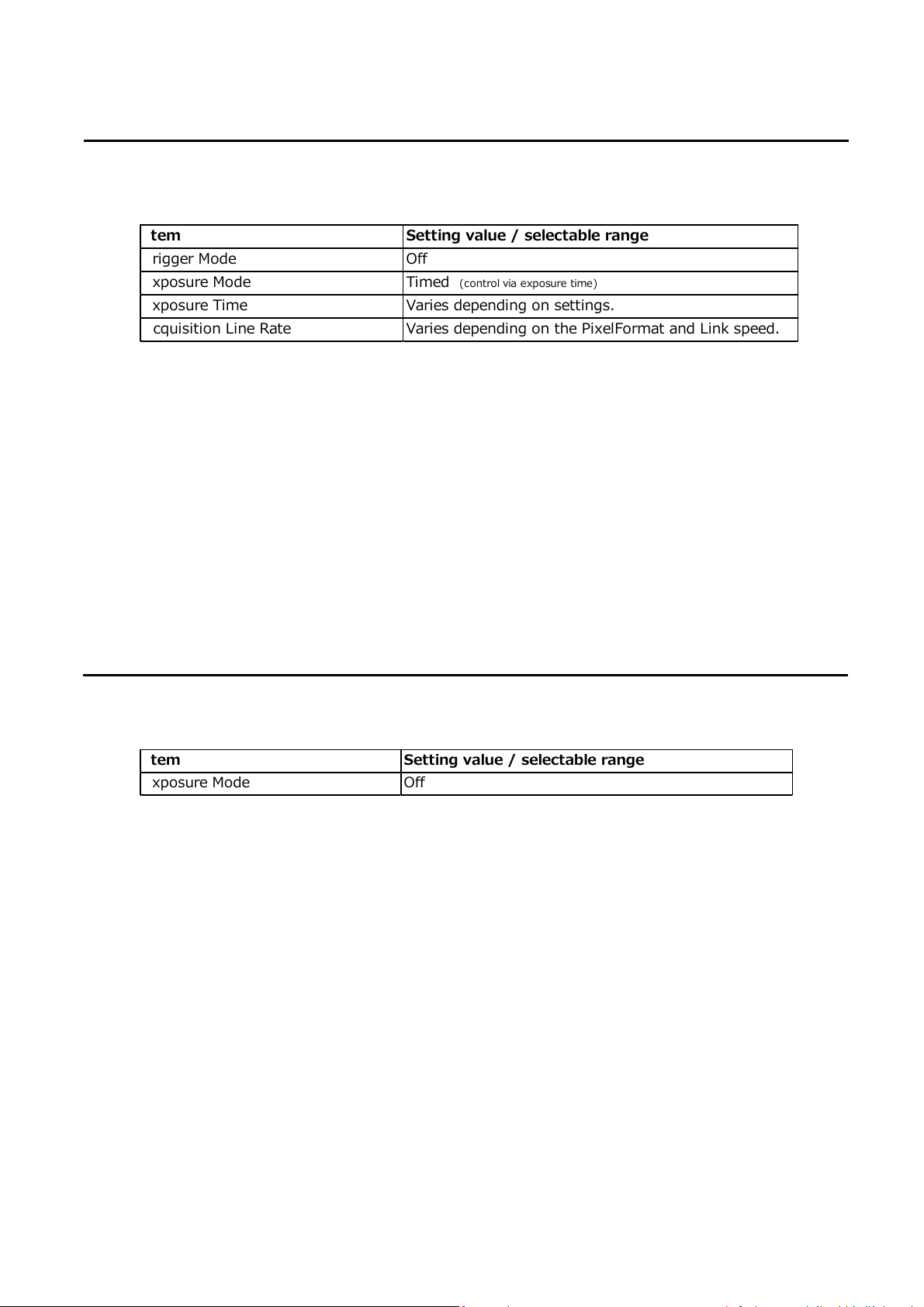
Item Setting value / selectable range
Exposure Mode Off
Item
Setting value / selectable range
Trigger Mode Off
Exposure Mode Timed
(control via exposure time)
Exposure Time Varies depending on settings.
Acquisition Line Rate Varies depending on the PixelFormat and Link speed.
■Control Without External Triggers
When Controlling the Exposure Time Using Specified Exposure Times
Configure the settings as follows.
Set [Exposure Mode] to [Timed].
1
SW-4000Q-10GE
Set [Trigger Mode] to [Off].
2
Specify a line period slower than the exposure time in [Acquisition Line Rate].
3
Specify the exposure time in [Exposure Time].
4
When Not Controlling the Exposure Time
Configure the settings as follows.
The exposure will be performed with an exposure time equal to 1 / line rate.
* The exposure time specified in [Exposure Time] will be disabled.
— 19 —
Step 6: Adjusting the Image Quality
Display the camera image and adjust the image quality.
Displaying the Image
Display the image captured by the camera.
When you push [Play] button, the camera image appears in right area.
*) By default settings, the video in the visible region are displayed.
SW-4000Q-10GE
To maximize the performance of the camera, configure its basic function in the following
order.
Configure the line rate.
1
◇ For details on this setting, “Variable Line Rate”.
Configure the exposure time.
2
◇ For details on this setting, “Electronic Shutter” .
Perform DSNU correction.
3
◇ For details on this setting, “Pixel Sensitivity Correction”.
Perform PRNU correction.
4
◇ For details on this setting, “Pixel Sensitivity Correction” .
Adjust the black level.
5
◇ For details on this setting, “Black Level Correction”.
— 20 —

Adjust the white balance.
6
Adjust the white balance using the automatic adjustment function.
① Place a white sheet of paper or similar object under the same lighting conditions as
the intended subject, and zoom in to capture the white.
White objects near the subject, such as a white cloth or wall, can also be used.
Be sure to prevent the high-intensity spot lights from entering the screen.
The white balance is automatically adjusted.
② Select the [Balance White Auto] tab, and select [Once].
The white balance is automatically adjusted.
Step 7: Saving the Settings
The setting values configured in the player (eBUS SDK for JAI) will be deleted when the
camera is turned off. By saving current setting values to user memory, you can load and
recall them whenever necessary. You can save up to three sets of user settings in the
camera. (User Set1 to 3)
SW-4000Q-10GE
Memory(Flash)
DefaultSet
UserSet1
UserSet2
UserSet3
一時メモリ
Memory(RAM)
Working Set
Note
Changes to settings are not saved to the computer (eBUS SDK for JAI).
■ To save user settings
eBUS SDK for
JAI (Player)
Stop image acquisition.
1
Expand [UserSetControl], and select the save destination ([UserSet1] to
2
[UserSet3]) in [UserSetSelector].
Note
The factory default setting values are stored in [Default] and cannot be overwritten.
Caution
Settings can only be saved when image acquisition on the camera is stopped.
— 21 —

Select [UserSetSave], and click [UserSetSave].
3
The current setting values are saved as user settings.
■ To load user settings
Stop image acquisition.
1
User settings can only be loaded when image capture on the camera is stopped.
Select the settings to load (UserSet1 to UserSet3) in [UserSetSelector].
2
Select [UserSetLoad], and click [UserSetLoad].
3
The selected user settings are loaded.
SW-4000Q-10GE
— 22 —

Main Functions
Line4 TTL In 1 ○ ○ ○ ○ ○ ○ ○ ○ ○ ○ ○ ○ ○ ○ ○
Line5 Opt In 1 ○ ○ ○ ○ ○ ○ ○ ○ ○ ○ ○ ○ ○ ○ ○
Line10 TTL In 2 ○ ○ ○ ○ ○ ○ ○ ○ ○ ○ ○ ○ ○ ○ ○
Line13 TTL In 3 ○ ○ ○ ○ ○ ○ ○ ○ ○ ○ ○ ○ ○ ○ ○
UserOutput0 ○ ○ ○ ○ ○ ○ ○ ○ ○ ○ ○ ○ ○ ○ ○
UserOutput1 ○ ○ ○ ○ ○ ○ ○ ○ ○ ○ ○ ○ ○ ○ ○
UserOutput2 ○ ○ ○ ○ ○ ○ ○ ○ ○ ○ ○ ○ ○ ○ ○
UserOutput3 ○ ○ ○ ○ ○ ○ ○ ○ ○ ○ ○ ○ ○ ○ ○
Action0 ○ ○ ○ ○ ○ ー ー ー ー ー ー ー ー ー ー
Action1 ○ ○ ○ ○ ○ ー ー ー ー ー ー ー ー ー ー
Action2 ○ ○ ○ ○ ○ ー ー ー ー ー ー ー ー ー ー
Action3 ○ ○ ○ ○ ○ ー ー ー ー ー ー ー ー ー ー
PulseGenerator0 ○ ○ ○ ○ ○ ○ ○ ○ ○ ○ ○ ー ー ー ー
PulseGenerator1 ○ ○ ○ ○ ○ ○ ○ ○ ○ ○ ○ ー ー ー ー
PulseGenerator2 ○ ○ ○ ○ ○ ○ ○ ○ ○ ○ ○ ー ー ー ー
PulseGenerator3 ○ ○ ○ ○ ○ ○ ○ ○ ○ ○ ○ ー ー ー ー
Encoder Trigger ○ ○ ○ ○ ○ ○ ○ ○ ○ ○ ○ ○ ○ ○ ○
Encoder Direction ー ー ー ー ー ○ ○ ○ ○ ○ ○ ○ ○ ○ ○
Logic Block 0 ○ ○ ○ ○ ○ ○ ○ ○ ○ ー ○ ○ ○ ○ ○
Logic Block 1 ○ ○ ○ ○ ○ ○ ○ ○ ○ ○ ー ○ ○ ○ ○
Acquisition Active ー ー ー ー ー ○ ○ ○ ○ ○ ○ ー ー ー ー
Exposure Active ー ー ー ー ー ○ ○ ○ ○ ○ ○ ○ ○ ○ ○
LVAL ー ー ー ー ー ○ ○ ○ ○ ○ ○ ○ ○ ○ ○
Signals to use as output
Output destination
Pulse Generator 0
Pulse Generator 1
Pulse Generator 2
Pulse Generator 3
Logic Block 0
Logic Block 1
Acquisition Start
Acquisi tion End
Frame Start
Frame T ransfer Start
Trigger Selector
Line Selector
Pulse Generator Selector
Trigger Selector
Pulse Generator Selector
Line Selector
Use
Line Start
Line8 TTL Out 2
Line9 TTL Out 3
Line12 TTL Out 4
Line1 TTL Out 1
Valid Input / Output Combinations
The following signals can be used as sources for each output destination (Trigger Selector,
Line Selector, Pulse Generator Selector).
You can also connect two different sources to NAND paths in the GPIO and reuse the signal
generated there as a source for a different selector.
The combinations of source signals and output destinations are indicated in the following.
Selector
(Cross point
switch output)
SW-4000Q-10GE
Source Signal
(Cross point
switch input)
— 23 —

Line1 TTL Out 1
DC IN / TRIG IN connector (12 pin)
Line8 TTL Out 2 AUX connector (10 pin)
Line9 TTL Out 3 AUX connector (10 pin)
Line12 TTL Out 4 DC IN / TRIG IN connector (12 pin)
Line4 TTL In 1 DC IN / TRIG IN connector (12 pin)
Line5 Opt In 1 DC IN / TRIG IN connector (12 pin)
Line10 TTL In 2 AUX connector (10 pin)
Line13 TTL In 3 AUX connector (10 pin)
External
output
External
input
GPIO (Digital Input / Output Settings)
The unit can input/output the following signals to and from external input/output connectors.
These signals can be used as triggers and other necessary signals within the camera or as
signals output from the camera to the system, such as those used for lighting equipment
control.
Signals are selected as follows.
• When using external signals or the signals of each GPIO module as trigger signals:
Select in [Trigger Selector] > [Trigger Source].
• When selecting the signals to use for external outputs:
Select in [Line Selector] > [Line Source].
SW-4000Q-10GE
— 24 —

Pixel format
Stream 0 Stream 1
1 RGB8 Mono8
2 RGB8 Mono10Packed
3 RGB10V1Packed Mono8
4 RGB10V1Packed Mono10Packed
5 RGB10p32 Mono8
6 RGB10p32 Mono10Packed
7 YUV422_8 Mono8
8 YUV422_8 Mono10Packed
9 YUV422_8_UYVY Mono8
10 YUV422_8_UYVY Mono10Packed
This camera can capture the image in the visible region and the near infrared region (NIR)
simultaneously.
There are the following two ways of sending data of the two captured images from the camera.
1. Single-stream output
Stream 0
SW-4000Q-10GE
…
NIR
NIR
R
G
B
B
NIR
R
G
B
NIR
R
G
R
G
B
Support PixelFormat : RGBa8
2. Dual-stream output
Stream 0
Stream 1
…
…
R
R
G
B
NIR
B
R
G
B
NIR
NIR
R
G
B
R
G
B
NIRNIR
Support PixelFormat :
Stream 0 ( RGB8, RGB10V1Packed, RGB10p32, YUV422_8, YUV422_8_UYVY )
Stream 1 ( Mono8, Mono10Packed )
There are ten combinations of PixelFormat that can be set as shown below.
The fastest line rate can be realized by setting 7.YUV422_8, Mono8 or 9.YUV422_8_UYVY, Mono8
With the smallest number of bits per pixel.
By setting 4.RGB10V1Packed, Mono10Packed or 6.RGB10p32, Mono10Packed, which has the largest
number of bits per pixel, the highest image quality can be taken.
— 25 —

SW-4000Q-10GE
ComponentSelector = RGB ComponentSelector = NIR
1 Single-Stream RGBa8 ー
Stream 0 Stream 1
2 RGB8 Mono8
3 RGB8 Mono10Packed
4 RGB10V1Packed Mono8
5 RGB10V1Packed Mono10Packed
6 RGB10p32 Mono8
7 RGB10p32 Mono10Packed
8 YUV422_8 Mono8
9 YUV422_8 Mono10Packed
10 YUV422_8_UYVY Mono8
11 YUV422_8_UYVY Mono10Packed
Dual-Stream
Note
Stream 0, Stream 1 are two UDP streams, each assigned a different port number.
The assigned port number can be confirmed with the following settings.
In [TransportLayerControl] - [GevStreamChannelSelector], select the stream whose port number
you want to check, the port number will be displayed in [GevSCSP].
Setting the pixel format
The pixel format is set with [ComponentSelector] and [PixelFormat].
Single-Stream output
1. Select [RGB] in [ImageFormatControl] – [ComponentSelector].
2. Select [RGBa8] in [PixelFormat].
Dual-Stream output
First stream (Stream 0) setting.
1. Select [RGB] in [ImageFormatControl] – [ComponentSelector].
2. Select [RGB8, RGB10V1Packed, YUV422_8_UYVY or YUV422_8] in [PixelFormat].
Second stream (Stream 1) setting.
1. Select [NIR] in [ImageFormatControl] – [ComponentSelector].
2. Select [Mono8 or Mono10Packed] in [PixelFormat].
There are eleven combinations of PixelFormat that can be set as shown below.
— 26 —

Exposure Mode
Exposure Mode Trigger Mode
OFF
ON
OFF
ON
Trigger Width
ON
Operation mode
OFF
Timed
Imaging of one frame is started by input of external trigger signal.
Start image acquisition in response to the external trigger signal input.
Stop image acquisition in response to the external trigger signal input.
Output acquired images at a specified timing in response to an external
trigger signal input.
* There is a limit to the number of image frames that can be stored
Imaging of one line is started by input of external trigger signal.
The following operation modes are available on the camera.
Image Output Timing
■ Trigger Control
SW-4000Q-10GE
In this camera, the following control is performed by the external trigger signal.
Trigger Selector Description
FrameStart
AcquisitionStart
AcquisitionEnd
FrameTransferStart
internally.
Example : (PixelFormat RGBa8, Width 4096, Height 4096)
It is possible to hold 3 frames of images.
Line Start
— 27 —

■ When [Exposure Mode] is [OFF]
Delay Time from
Exposure Active
Trigger
B1
B2
Exposure Active
Readout
Pixel Format Width
Trigger
Period[A]
(μs)
A
(*)(**)
Trigger to
Exposure
Active[B1]
(μs)
C
Expousre Active
Non Active[B2]
(μs)
Period from
Falling
to Readout
Start[C]
(μs)
SW-4000Q-10GE
D
Readout
Period[D]
(μs)
RGB10V1Pack
RGB10p32
YUV422_8
YUV422_8_UY
*) H Binning = Off
**) GevGVSPExtendedIDMode = Off, GevSCPDPacketSize = 8976
RGB8
RGBa8
ed
VY
4096 14.70 0.4 3.6 37.0 6.56
2048 7.69 0.4 3.6 30.4 3.28
16 5.45 0.4 3.6 23.9 0.03
4096 14.49 0.4 3.6 37.0 6.56
2048 7.37 0.4 3.6 30.4 3.28
16 5.45 0.4 3.6 23.9 0.03
4096 18.27 0.4 3.6 37.0 6.56
2048 9.42 0.4 3.6 30.4 3.28
16 5.45 0.4 3.6 23.9 0.03
4096 18.27 0.4 3.6 37.0 6.56
2048 9.42 0.4 3.6 30.4 3.28
16 5.45 0.4 3.6 23.9 0.03
4096 13.52 0.4 3.6 37.0 6.56
2048 6.76 0.4 3.6 30.4 3.28
16 5.45 0.4 3.6 23.9 0.03
4096 13.53 0.4 3.6 37.0 6.56
2048 6.76 0.4 3.6 30.4 3.28
16 5.45 0.4 3.6 23.9 0.03
— 28 —

■ When [Exposure Mode] is [Timed]
Pixel Format Width
Trigger
Period[A]
(μs)
(*)(**)
Delay Time from
Trigger Rising to
Exposure Active
Rising[B]
(μs)
Period from
Exposure Active
Falling
to Readout
rising[C]
(μs)
Readout
period[D]
(μs)
4096 14.70
0.27 37.0
6.56
2048 7.69
0.27
30.4 3.28
16 5.45 0.27 23.9 0.03
4096 14.49 0.27 37.0 6.56
2048 7.37 0.27 30.4 3.28
16 5.45 0.27 23.9 0.03
4096 18.27 0.27 37.0 6.56
2048 9.42 0.27 30.4 3.28
16 5.45 0.27 23.9 0.03
4096 18.27 0.27 37.0 6.56
2048 9.42 0.27 30.4 3.28
16 5.45 0.27 23.9 0.03
4096 13.52 0.27 37.0 6.56
2048 6.76 0.27 30.4 3.28
16 5.45 0.27 23.9 0.03
4096 13.53
0.27 37.0 6.56
2048 6.76 0.27 30.4
3.28
16
5.45 0.27 23.9 0.03
RGB8
RGBa8
RGB10V1Packed
RGB10p32
YUV422_8
YUV422_8_UYVY
A
Trigger
B
Exposure Active
Readout
SW-4000Q-10GE
C D
*) H Binning = Off
**) GevGVSPExtendedIDMode = Off, GevSCPDPacketSize = 8976
— 29 —

■ When [Exposure Mode] is [Trigger Width]
Pixel Format Width
Trigger
Period[A]
(μs)
(*)(**)
Delay Time from
Trigger Rising to
Exposure Active
Rising[B]
(μs)
Period from
Exposure Active
Falling
to Readout
Start[C]
(μs)
Readout
period[D]
(μs)
Delay Time from
Trigger Falling
to Exposure
Active Falling[E]
(μs)
4096 14.70 0.26 37.0 6.56 0.3
2048 7.69 0.26 30.4 3.28 0.3
16 5.45 0.26 23.9 0.03 0.3
4096 14.49 0.26 37.0 6.56 0.3
2048 7.37 0.26 30.4 3.28 0.3
16 5.45 0.26 23.9 0.03 0.3
4096 18.27 0.26 37.0 6.56 0.3
2048 9.42 0.26 30.4 3.28 0.3
16 5.45 0.26 23.9 0.03 0.3
4096 18.27 0.26 37.0 6.56 0.3
2048 9.42 0.26 30.4 3.28 0.3
16 5.45 0.26 23.9 0.03 0.3
4096 13.52 0.26 37.0 6.56 0.3
2048 6.76 0.26 30.4 3.28 0.3
16 5.45 0.26 23.9 0.03 0.3
4096 13.53 0.26 37.0 6.56 0.3
2048 6.76 0.26 30.4 3.28 0.3
16 5.45 0.26 23.9 0.03 0.3
YUV422_8_UYVY
RGB8
RGBa8
RGB10V1Packed
RGB10p32
YUV422_8
A
Trigger
SW-4000Q-10GE
Exposure Active
Readout
B
E
C
D
*) H Binning = Off
**) GevGVSPExtendedIDMode = Off, GevSCPDPacketSize = 8976
— 30 —

Pixel Sensitivity Correction
Correct variations between the sensor’s pixels.
Calibration must be performed within the camera and correction data must be created
beforehand. DSNU (Pixel Black Correct) / PRNU (Pixel Gain Correct) can be reduced using
that correction data. We recommend performing calibration and creating correction data
whenever the line rate setting is changed significantly.
◇ Correction data is saved for DSNU (Pixel Black Correct) / PRNU (Pixel Gain Correct)
according to the conditions adjusted at the factory. Perform calibration whenever changing
setting, such as the Acquisition Line Rate setting, and use the correction data for DSNU
(Pixel Black Correct) / PRNU (Pixel Gain Correct).
◇ Perform DSNU (Pixel Black Correct) calibration again whenever the exposure time or
analog base gain value is adjusted.
◇ A single correction data entry can be saved on the camera for each user. When calibration
is performed, the correction data is saved to the non-volatile ROM at the same time.
PRNU Correction (Pixel Gain Correct)
PRNU (photo response non-uniformity) is a variation between pixels generated by the sensor
under bright conditions. If the line rate is slowed or a long exposure time is set, the dark
current in the sensor may change and the state of the PRNU may change.
SW-4000Q-10GE
DSNU Correction (Pixel Black Correct)
DSNU (dark signal non-uniformity) is a variation between pixels in the dark areas generated
by the sensor. If the line rate is slowed or a long exposure time is set, the dark current in the
sensor may change and the state of the DSNU may change.
Black level
— 31 —

Gain Control
The following gain functions are available on the camera.
• Analog base gain
• Digital gain
■ Analog base gain
Analog base gain (ABG) is gain that is performed to the analog video signal output from the
sensor. The gain steps can be configured to one of three levels (0 dB, 6 dB, 12 dB).
■ Two digital gain control modes
Two digital gain control modes are available; a mode where you adjust the master gain and
then perform fine adjustment for R, B and NIR (Master Mode), and a mode where R, G, B
and NIR gain are adjusted individually (Individual Mode).
・Master Mode
Set [Individual Gain Mode] to [Off], and adjust the gain by configuring the following four
items.
Digital All x 1 ~ x 8 ( 0dB ~18dB)
Digital Red x 0.67 ~ x 4 (-4dB ~ 12dB)
Digital Blue x 0.67 ~ x 4 (-4dB ~ 12dB)
Digital NIR x 0.67 ~ x 4 (-4dB ~ 12dB)
SW-4000Q-10GE
・Individual Mode
Set [Individual Gain Mode] to [On], and adjust the gain by configuring the following four
items.
Digital Green x 1 ~ x 16 (0dB ~ 24dB)
Digital Red x 1 ~ x 16 (0dB ~ 24dB)
Digital Blue x 1 ~ x 16 (0dB ~ 24dB)
Digital NIR x 1 ~ x 16 (0dB ~ 24dB)
The following two gain values are added together for the total gain value.
Total Gain = Analog Base Gain (dB) + Digital Gain (dB)
— 32 —

Item
Setting value /
selectable range
Description
LUTMode LUT Use LUT.
LUTSelector* Red, Green, Blue Select the LUT channel to control.
LUTIndex 0 ~ 256
Select the LUT index to configure. Indexes represent the
possible pixel values captured on the sensor, from the
lowest value (Index 0) to the highest (Index 256). For
example, Index 0 represents a full black pixel and Index
256 represents a full white pixel.
LUTValue 0 ~ 4095 Set the LUT output value for the selected index.
Lookup Table(LUT)
The LUT function is used to generate a non-linear mapping between signal values captured on
the sensor and those that are output from the camera.
You can specify the output curve using 257 setting points (indexes).
■ To use the LUT function
Configure the settings as follows.
SW-4000Q-10GE
■ LUT Value
LUT values range from 0 at the lowest to 4095 at the highest. Linear interpolation is used to
calculate LUT values between the index points.
4095
LUTValue[256]
Values between points are determined
using the linear interpolation values of
data to the left and right.
LUTValue[2]
LUTValue[1]
LUTValue[0]
0
Index0
Index1 Index2
Index256
— 33 —

Item
Setting value /
selectable range
Description
Gamma
0.45, 0.5, 0.55, 0.6, 0.65,
0.75, 0.8, 0.9, 1.0
Select the gamma correction value.
LUTMode Gamma Use gamma.
Gamma Function
The gamma function corrects the output signals from the camera beforehand (reverse
correction), taking into consideration the light-emitting properties of the monitor display. As
the light-emitting properties of the monitor are not linear, the entire image may be darker or
the gradation in the dark areas may be less noticeable when camera outputs are displayed
without processing. The gamma function can be used to correct the camera signals with an
opposite-direction curve and produce a display that is close to linear.
Y
1.2
1.0
<- Output
0.8
0.6
0.4
0.2
0
Input ->
Example of the light-emitting
properties of the monitor display
X
SW-4000Q-10GE
■ To use the gamma function
Configure the settings as follows.
Note
You can use the LUT function to configure a curve with more detailed points. For details, see
“Lookup Table (LUT)”.
— 34 —

Shading Correction
The shading correction is a function that corrects non-uniformity (i.e., shading) in the amount
of light generated by the lens and lighting equipment.
The following shading correction modes are available on the camera。
■ Flat shading correction
Correct so that the part with the highest luminance level in the screen is taken as the
reference and the other part is adjusted to this luminance level.
SW-4000Q-10GE
◇ Complete correction may not be possible depending on the optical system and light source
you are using.
◇ Data based on corrections performed under factory conditions is stored for this function.
■ Color shading correction
R-channel, B-channel and NIR-channel properties are adjusted by using the G-channel
shading properties as a reference.
Pre-correction Post-correction
■ To perform the shading function
The function is turned ON/OFF via serial communication. This function is not dependent on
the operation mode, but is effective when used during actual use.
◇ You can also save the setting and have it applied whenever the power is subsequently turned
on. For details on saving the setting, see “Step 7: Saving the Settings”
Caution
・For Flat Shading and Color Shading, the maximum correction gain amount is limited to 8 times
the gain amount before correction in all pixels.
・If the highest luminance level in the image is 175 LSB (10 bit image output) or less, it can not
be corrected correctly.
Black Level Correction
Black level correction is a function for adjusting the setup level.
When this function is used, the following is performed for the gain mode setting.
Digital All -133 ~+255 (LSB@12bit)
Digital Red -64 ~ +64 (LSB@12bit)
Digital Blue -64 ~ +64 (LSB@12bit)
Digital NIR -64 ~ +64 (LSB@12bit)
— 35 —

Variable Line Rate
You can set the line rate to 1L or more. This function can be used to match the scanning
speed of the camera to the feeding speed of the object or to lengthen the accumulation time
to increase sensitivity.
• Variable range: RGBa8 66Hz*~ 73kHz
RGB8 + Mono8 66Hz*~ 72kHz
YUV422_8 + Mono8 66Hz*~ 74kHz
*) When taking a trigger signal from the outside, there is no limitation on the minimum value.
• Variable unit: 0.1 Hz
• Supported operation modes: Exposure Mode OFF / Trigger OFF
Exposure Mode Timed / Trigger OFF
◇ You can also save the setting and have it applied whenever the power is subsequently
turned on, but this requires additional operations.
◇ Switching and settings storage for this function is performed via serial communication.
◇ The black level will change depending on the line rate, so be sure to readjust the black
level after changing the line rate or trigger period.
Electronic Shutter
SW-4000Q-10GE
When you use this function, you can set the exposure to a preconfigured accumulation time,
regardless of the line rate.
• Variable range: 3 μs to 15.149 ms
• Variable unit: 0.01 μs (1clk)
• Supported operation modes: When Trigger Mode ON, Exposure Mode Timed
Caution
In “Trigger Mode OFF, Exposure Mode Timed” mode, the line rate configured will be the
maximum value at which the shutter operates. However, in “Trigger Mode ON, Exposure Mode
Timed” mode, the input trigger period will be the maximum value.
◇ You can also save the setting and have it applied whenever the power is subsequently
turned on, but this requires additional operations.
EEN (Exposure Enable) Function
Perform external output for the timing at which video is accumulated to the sensor.
The signal is output to the DC IN / TRIG IN connector (12-pin round) or AUX connector.
Example: Output to DC IN/TRIG IN connector (12-pin round)
Trigger
( Internal / External )
Exposure
EEN
Test Pattern Function
You can display the following types of test patterns (Off, White, GrayPattern1, GrayPattern2,
ColorBar). Video output is not possible while a test pattern is being executed. This function is
not dependent on gain and offset values that have already been configured.
◇ This function cannot be saved as the initial state of the camera.
— 36 —

SW-4000Q-10GE
ColorTransformation ColorTransformationMode ColorTransformationRGBMode
RGB(sRGB) RGB sRGB
RGB(AdobeRGB) RGB AdobeRGB
RGB( UserCustom) RGB UserCustom
XYZ XYZ Off
H S I H S I Off
Default RGB Off
Setting value Description
ColorMatrixValueSelector
ColorMatrixR -R, ColorMatrixR-G, ColorMatrixR-B,
ColorMatrixG-R , ColorMatrixG-G, ColorMatrixG-B,
ColorMatrixB-R , ColorMatrixB-G, ColorMatrixB-B
Select the ColorMatrix setting
component.
ColorMatrixValue -2 to 2 Set th e Color Matrix v alue.
Item
Color Space Conversion (Color Transformation Control)
The SW-4000Q-10GE model allows you to convert the standard color space (RGB) that is
used to produce colors into other color spaces, including XYZ and HSI.
Five color spaces are available: RGB(sRGB), RGB(AdobeRGB), RGB(UserCustom), XYZ, and
HSI. Specify the
Transformation RGB Mode as follows.
*) This function is valid only when PixelFormat is RGBa8, RGB8, RGB10V1Packed, RGB10p32.
Caution
desired color space by configuring Color Transformation Mode and Color
If you set the color space to XYZ or HSI, eBUS Player for JAI will not display the images captured
by the camera properly. To display them properly, XYZ- or HSI-compatible image processing
must be performed on the computer side.
Note
Color space (HSI)
Value of Hue : For 0°-360°, specify as follows.
8bit output: 2°/step 0°(00000000) ~ 360°(10110100)
10bit output: 0.5°/step 0°(0000000000) ~ 360°(1011010000)
Value of Saturation, Intensity: For 0% - 100%, specify as follows.
8bit output: 0%(00000000) ~ 100%(11111111)
10bit output : 0%(00000000) ~ 100%(1111111111)
■ Note on RGB (UserCustom)
This allows you to use user configured 3x3 conversion tables to perform color space conversion.
Source data
R in
ColorMatrixValue[ColorMatrixValueSelector]
RR RG RB
3x3 table :
Destination data
R out
G in
B in
Configuration 3x3 table. Select the item you want to configure in [ColorMatrixValueSelector].
And configure the value in [ColorMatrixValue]. [ColorMatrixValue] can be set to a value from -2
to +2.
GR GG GB
BR BG BB
— 37 —
G out
B out

Counter And Timer Control Function
This camera supports only the counter function.
The counter function counts up change points in the camera’s internal signals using the
camera’s internal counter, and reads that information from the host side. This function is
useful for verifying error conditions via the count value using internal camera operations.
Six counters are available on the camera; Counter0, Counter1, Counter2, Counter3, Counter4
and Counter5.
The functions that can be counted are fixed for each counter.
Counter0: Counts the number of Line Trigger instances.
Counter1: Counts the number of Line Start instances.
Counter2: Counts the number of Exposure Start instances.
Counter3: Counts the number of Frame Trigger instances.
Counter4: Counts the number of Frame Start instances.
Counter5: Counts the number of Frame Transfer End instances.
When a problem occurs in a system that includes this camera, comparing the values from
multiple counters allows you to verify the extent of normal operability and can be useful when
investigating the cause of the problem.
SW-4000Q-10GE
■ Counter occurrence diagram
Line Trigger
Counter0
Exposure Start
Counter2
Event occurrence
Count up
Event occurrence
Count up
Counter2
Request
Counter0
Request
Read count
value
MCU
HOST
Read out
value
Counter reset
Count 0 reset
Counter reset
Counter2 reset
Note
You can reset a specific counter's count value by executing CounterReset[Counter0, Counter1,
Counter2, Counter3, Counter4, Counter5].
— 38 —

Setting value /
selectable range
Description
Counter 0 ~ 5 Select the counter.
CounterEventSource
Counter0
Off, Line Trigger
Counter1
Off, Line Start
Counter2
Off, Exposure Start
Counter3
Off, Frame Trigger
Counter4
Off, Frame Start
Counter5
Off, Frame Transfer End
Select the counter event signal
for which to read the count
value.
When set to Off, the counter
operation will stop (but will not
be reset).
CounterEventActivation
Counter0 Rising Edge
Counter1 Rising Edge
Counter2 Rising Edge
Counter3 Rising Edge
Counter4 Rising Edge
Counter5 Falling Edge
Specify timing at which to count.
(This setting is fixed.)
Item
Counter 0 ~ 5
■ Internal camera blocks
SW-4000Q-10GE
Counter0
Line Trigger
Counter1
Line Start
Counter2
Exposure Start
Counter5
Frame Transfer End
Event detection
Event detection
・
・
・
Event detection
Event detection
Counter reset
Internal MCU of camera
At event oc currence or count up
At event oc currence or count up
Counter
At event oc currence or count up
Counter
At event oc currence or count up
Counter
Counter
Read requested counter value
Send information
to the HOST
■ To use the counter function
Configure the settings as follows.
Six counters are available. Specify a counter (Counter0 to Counter5), and configure the
settings.
— 39 —

Chromatic Aberration Correction
This Function corrects for the chromatic aberration of magnification caused by the lens (i.e.,
when the size of the image differs at the focal point for each color (RGB)). You can save
correction data for three types of lenses. This function assumes that the amount of deviation
between the left and right is identical. If the amount of deviation between the left and right is
not identical, correction will not be performed properly. Specify the number of pixels to delay
or advance the R channel and B channel using the G channel as a reference. The correction
range is –4.0 to +4.0 in steps of 0.1.
■ Adjustment procedure
Enable the chromatic aberration of magnification correction function.
1
Set [Chromatic Aberration Correction Mode] to [On].
Alternatively, select preset Lens1, Lens2, or Lens3.
Correct the R channel.
2
Set [Chromatic Aberration Correction Selector] to [RChannel].
Specify the amount of correction in [Chromatic Aberration Correction Lens1,2,3]
(–4.0 to +4.0 in steps of 0.1).
Similarly, correct the B channel.
3
Set [Chromatic Aberration Correction Selector] to [B Channel].
Specify the amount of correction in [Chromatic Aberration Correction Lens1,2,3]
(–4.0 to +4.0 in steps of 0.1).
SW-4000Q-10GE
Similarly, correct the NIR channel.
4
Set [Chromatic Aberration Correction Selector] to [NIR Channel].
Specify the amount of correction in [Chromatic Aberration Correction Lens1,2,3]
(–8.0 to +8.0 in steps of 0.1).
Connecting Rotary Encoders
This camera can generate trigger signals or detect the scanning direction of the subject in
response to signals output from the rotary encoder.
■ Adjustment procedure
Input the two signals (phase A and phase B) from the rotary encoder.
1
Select which I/O on the camera (Line5:OptIn1, Line4:TTLIn1, Line10:TTLIn2,
Line13:TTLIn3) you want to input each of the two outputs from the rotary encoder
[phase A (Encoder Source A), phase B (Encoder Source B)].
Specify the number of triggers (number of vertical lines) to generate during
2
each rotation of the rotary encoder.
When [Encoder Divider] is set to [N], the rotary encoder generates 65536/N triggers.
When N is an integer multiple of 65536
Camera internal trigger is generated by decimation of output trigger of rotary
encoder.
When N is not an integer multiple of 65536
Using the time interval of the output trigger of the rotary encoder, Camera internal
trigger is generated so that the set division ratio is obtained.
Note
If the time interval of the output of the rotary encoder fluctuates greatly, the output
of the camera internal trigger generated may also fluctuate greatly.
In this case, by setting [EncoderAveragingInterval], it is possible to perform internal
processing with the value obtained by averaging the time intervals of the specified
number of signals.
— 40 —

If necessary, enable the low-pass filter for the signal to prevent unintended
3
operations due to signal noise from the rotary encoder.
Specify the number of cycles from a range of 0 to 15 (0 to 150 ns).
If necessary, specify the strobe length of the generated signal.
4
When [EncoderStrobe] is set to [M], the strobe length will be [M]×10 ns.
Frame Start Trigger
In this camera, Data Leader and Data Trailer are added every frame.
The number of lines of one frame is set by Offset Y, Height of [Image Format Control].
Offset Y’s setting range is 0 to 4095.
Height setting range is 1 to 4096.
SW-4000Q-10GE
■One frame of image data (Offset Y = 0)
Data Trailer
(GigE Vision)
Data Leader
(GigE Vision)
・・・・・
Time passed
■ One frame of image data (Offset Y > 0)
Data Trailer
(GigE Vision)
Image data [ Number of lines (Height - Offset Y) ]
Data Leader
(GigE Vision)
・・・・・
Image data for the number of lines
Image data [ Number of lines (Height - Offset Y) ]
Time passed
When using Frame Start Trigger, after receiving Frame Start Trigger, skip the image data of
the number of lines of Offset Y and send the data of Data Leader, image data, Data Trailer.
(Upon completion of data transmission for one frame, no data will be sent until the next Frame
Start Trigger is received.)
specified by Offset Y will not be sent.
Frame Start
Trigger
One frame of image data
Time passed
One frame of image data
*) Chunk Data (first line of every frame only) is sent after Data Trailer.
— 41 —
Frame Start
Trigger

Binning Function
Offset X (pixels) Offset Y (pixels)
BinningHorizontal Off:
0 to 4080 step 16
BinningHorizontal On:
0 to 2040 step 8
0 to 4095 setp 1
Width (pixels) Height (pixels)
BinningHorizontal Off:
16 to 4096 step 16
BinningHorizontal On:
8 to 2048 step 8
1 to 4096 step 1
The binning function allows you to combine the signal values of clusters of adjacent pixels to
create improved virtual pixels. Using the function results in images with lower pixel resolution
and higher sensitivity.
This camera performs vertical binning via digital addition in the sensor.
This camera performs horizontal binning via digital addition processing.
ROI (Regional Scanning Function)
The ROI (region of interest) function allows you to output images by specifying the areas to
scan.
ROI Settings
Specify the area to scan by specifying width and horizontal offset values under [Image Format
Control].
The setting ranges for the ROI function's readable area based on the Binning setting (Binning
Horizontal) are as follows.
SW-4000Q-10GE
— 42 —

Chunk Data Function
The Chunk Data function adds camera configuration information to the image data that is
output from the camera. Embedding camera configuration information in the image data
allows you to use the serial number of the camera as a search key and find specific image data
from among large volumes of image data. In addition, when images are shot with a single
camera in sequence under multiple setting conditions, you can search for images by their
setting conditions.
■ Configuring Chunk Data
Set [ChunkModeActive] to [True].
1
Select the items of information you want added to image data with
2
[ChunkSelector], and set [ChunkEnable] from [False] to [True].
Note
When [ChunkModeActive] is set to [True], [ChunkImage] is automatically set to [True].
SW-4000Q-10GE
Caution
The Chunk Data function settings cannot be changed during image output. To change the
settings, stop Acquisition.
*) For items that can be added to image data as Chunk Data, refer to [n) ChunkDataControl]
in the setting item list.
Delayed Readout
Delayed readout allows images captured by a [Frame Start] trigger command to be stored
temporarily inside the camera (delayed readout buffer) and read out using a
[FrameTransferStart] trigger after capture.
This function is useful when executing triggers simultaneously on multiple cameras.
Note
This function imposes a heavy processing load on the network bandwidth, as images from
multiple cameras are read out simultaneously.
* About delayed readout buffer size, refer to “Trigger Control”.
— 43 —

Event Control Function
The Event Control Function is a function that outputs a signal change point inside the camera
as information indicative of an event occurrence (event message) by using GVCP (GigE Vision
Control Protocol).
■ Flow from detecting an event to sending an event message
Event signal
SW-4000Q-10GE
Detect an event
Interrupt signal
MCU inside the camera
Keep the event type and
timestamp value when an event
occurs.
Reset event information after an
event message has been sent
Send an event message
■ Events that can use the Event Control Function
Events that can use the Event Control Function are as follows. You can specify whether or not
to send an event message when an event occurs at each event.
Acquisition Start, Acquisition End,
Frame Start, Frame End,
Line Start, Line End,
Exposure Red Start, Exposure Red End,
Exposure Green Start, Exposure Green End,
Exposure Blue Start, Exposure Blue End,
Line1 Rising Edge, Line1 Falling Edge,
Line4 Rising Edge, Line4 Falling Edge,
Line5 Rising Edge, Line5 Falling Edge,
Line8 Rising Edge, Line8 Falling Edge,
Line9 Rising Edge, Line9 Falling Edge,
Line10 Rising Edge, Line10 Falling Edge,
Line12 Rising Edge, Line12 Falling Edge,
Line13 Rising Edge, Line13 Falling Edge,
LVAL Start, LVAL End
ExposureNIRStart, ExposureNIREnd
— 44 —

Action Control Function
The Action Control Function is a function that executes the pre-configured action when the
camera receives action commands. Action commands can send both unicast and broadcast
messages and give instructions for actions to multiple cameras simultaneously by broadcasting
them. A camera that has this function can even give instructions for actions to different types
of multiple cameras. Although this function includes jitter and delays, it is useful for controlling
multiple cameras simultaneously.
Actions are performed when the following three conditions are met.
1. ActionDeviceKey set to the camera and ActionDeviceKey in the action command match
2. ActionGroupKey set to the camera and ActionGroupKey in the action command match
3. ActionGroupMask set to the camera and GroupMask in the action command perform AND
operation, and the result is not 0.
■ About the settings of the camera
1. Specify ActionDeviceKey.
2. Then, specify two actions that can be configured on the camera.
Action1
Select 1 in ActionSelector.
Specify ActionGroupMask [ActionSelector].
Specify ActionGroupKey [ActionSelector].
Action2
Select 2 in ActionSelector.
Specify ActionGroupMask [ActionSelector].
Specify ActionGroupKey [ActionSelector].
3. Set triggers (AcquisitionStart, AcquisitionEnd, FrameStart, AcquisitionTransferStart) to
Action1 and Action2.
SW-4000Q-10GE
■ Setting example
Assume that the following settings have been pre-configured on the camera.
ActionDeviceKey : 0x00001001
ActionGroupMask[1] : 0x00000011
ActionGroupKey[1] : 0x00000001
ActionGroupMask[2] : 0x00000111
ActionGroupKey[2] : 0x00000002
When the camera receives action commands (ActionDeviceKey:0x00001001, ActionGroupMask:0x00000011,
ActionGroupKey: 0x00000002), Action2 is executed.
When the camera receives action commands (ActionDeviceKey:0x00001001, ActionGroupMask:0x00000011,
ActionGroupKey: 0x00000001), ActionDevice and ActionGroupKey[1] match. However, the result of AND operation
performed by ActionGroupMask is 0. Therefore, in this case, neither Action1 nor Action2 is executed.
— 45 —

Setting List
Feature Properties
SW-4000Q-10GE
a) Device Control
Item
Device Vendor Name
Device Model Name
Device Manufacturer Info
Device Version
Device Firmware Version
Device Fpga Version
Device Serial Number
Device User ID
Device SFNC Version Major
Device SFNC Version Minor
Device SFNC Version Sub Minor
Device Manifest Entry Selector
Device TL Type
Device TL Vision Major
Device TL Version Minor
Device TL Version Sub Minor
Device Link Selector
Device Link Speed (Bps)
Device Link Heartbeat Mode
Device Link Heartbeat Timeout (us)
Device Stream Channel Count
Device Event Channel Count
DeviceReset
DeviceTemperatureSelector
DeviceTemperature(C) ー ー Display the internal temperature (°C) of the camera.
Timestamp (ns)
Setting range Default value Description
ー "JAI Corporation" Display the manufacturer name.
ー SW-4000Q-10GE Display the model name.
ー See the possibilities Display the manufacturer information.
ー ー Display the hardware version.
ー ー Display the firmware version.
ー ー Display the FPGA version.
ー ー Display the device ID.
Any ー Set the user ID (16bytes) for the camera.
2 2 Display the SFNC Major version.
3 3 Display the SFNC Minor version.
0 0 Display the SFNC Sub Minor version.
1 1 Display information on valid XML file.
GigE Vsion GigE Vsion Display type of transport layer.
2 2 Display the Major version of transport layer.
0 0 Display the Minor version of transport layer.
1 1 Display the Sub Minor version of transport layer.
0 0 Select I/F for control. (0 fixed)
ー ー Display Link spped.
Off, On On Set the mode of Link heartbeat.
500000 〜 120000000 3000000 Set the time of heartbeat timeout .
ー ー Display the number of stream channels.
ー ー Display the number of event channels.
ー ー Reset the device.
Mainboard Mainboard Select the area of the camera's interior for which to display the temperature
0〜9223372036854775807
(maximum value of unsigned
64-bit)
0
Display/configure information related to the device.
(After the camera receives this command, it returns an ACK response. Then,
execute reset.)
sensor's reading. (fixed Mainboard)
Display the timestamp value. Resets to 0 when the signed maximum 64-bit
value is exceeded.
Timestamp Reset
Timestamp Latch
Timestamp Latch Value (ns)
ー ー Forcibly sets the timestamp's count value to 0.
ーー
0〜9223372036854775807
(maximum value of unsigned
64-bit)
0
Sets the timestamp's count value to TimestampLatchValue.
— 46 —

SW-4000Q-10GE
b) ImageFormatControl
Item
WidthMax
HeightMax
Width
Height
Setting range Default value Description
Configure image format settings.
ー 4096 Display the maximum image width.
ー 4096 Display the maximum image height.
BinningHorizontal 1:
16〜4096 step 16
BinningHorizontal 2:
8〜2048 step 8
1 〜 4096 step 1
4096 Set the image width.
1 Set the image height (number of lines).
Image data with the specified number of lines will be streamed as 1 block.
OffsetX
OffsetY
BinningHorizontal
BinningVertical 1:
0 〜 4080 step 16
BinningVertical 2:
0 〜 2040 step 8
0 Set the horizontal offset.
0 〜 4095 0 Set the vertical offset.
1,2 1 Set the number of pixels in the horizontal direction for which to perform
binning. BinningMode is fixed to Sum.
SensorBinningVertical
1,2 1 Set the number of pixels in the vertical direction for which to perform
binning. BinningMode is fixed to Sum.
ComponentSelector
RGB, NIR RGB Select the component.
PixelFormat ー RGB8 Set the pixel format.
[Setting Range]
[Component Selector = RGB]
RGB8 (Default), RGB10V1Packed, RGB10p32
YUV422_8_UYVY, YUV422_8
RGBA8
[Component Selector = NIR]
Mono8 (Default) , Mono10Packed
*) In Component Selector = RGB, when PixelFormat is set RGBA8,
Pixel Format in ComponentSelector = NIR is invalid.
TestPattern
Horizontal Image Mirroring
Item
c) Acquisition Control
Acquisition Mode
Off,
White,
GrayPattern1(Ramp),
GrayPattern2(Stripe),
ColorBar
Off, On
Off Select the test image.
Off Invert the image left and right.
Setting range Default value Description
Configure image capture settings.
Single Frame,
Countinuous Select the image capture mode.
Multi Frame,
Continuous
Acquisition Start
Acquisition Stop
Acquisition Frame Count
Acquisition Frame Rate(Hz)
Acquisition Line Rate
ー ー Start image capture.
ー ー Stop image capture.
1〜65535 1 In [MultiFrame] mode, set the number of frames to capture.
ー 66 Display the frame rate as a frequency. (unit: Hz)
66 〜 66 Set the AcquisitionLineRate (Hz).
The maximum value varies depending on the PixelFormat and ROI settings.
Trigger Selector
ー
TriggerMode Off, On Off Select the trigger mode.
TriggerSource ー
TriggerActivation
ExposureMode
ExposureTimeMode
ExposureTimeSelector
RisingEdge,
FallingEdge,
Level High,
Level Low
Off, Timed, Trigger Width
Common, Individual Common Select the exposure time mode.
ExposureTimeMode:Common
Common,
ExposureTimeMode:Individual
Red,
Green,
Blue
Acquisition Start
Line4 TTL In 1
Rising Edge
Select the trigger operation.
[Setting range]
Acquisition Start, Acquisition End, Line Start, Frame Start, Frame Transfer Start
Select the trigger signal source.
[Setting range]
PulseGenerator0, PulseGenerator1, PulseGenerator2, PulseGenerator3
UserOutput0, UserOutput1, UserOutput2, UserOutput3
Action 0, Action 1, Action 2, Action 3
Line4 TTL In 1, Line5 Opt In 1, Line10 TTL In 2, Line13 TTL In 3
Logical Block 0, Logical Block 1, Encoder Trigger
Select the polarity of the trigger signal (i.e., location of signal at which
trigger is applied).
[Trigger Selector] = Line Start
ExposureMode is Off or Timed : RisingEdge, Falling Edge
ExposureMode is TriggerWidth : LevelHigh, LevelLow
Timed Select the exposure mode.
Common Select the sensor to set ExposureTime.
To set the common setting values for all three sensors, select Common
ExposureTime 3 〜 15149 Set the exposure time.
RBExposureInterlocked
Off, On Off When set to On, you can change Green while maintaining white balance.
47 —
—

SW-4000Q-10GE
d) Analog Control
Item
IndividualGainMode
Setting range Default value Description
Set whether to enable auto exposure.
Off, On Off In IndividualGainMode, R, G, B, NIR can be configured individually for the
entire gain adjustment range of the sensor.
GainSelector
IndividualGainMode : On
DigitalGreen,
DigitalRed,
DigitalBlue
IndidualGainMode : Off
DigitalAll,
DigitalRed,
DigitalBlue
ー Select the gain to configure.
Gain ー x1.0 Set the gain value for the gain setting selected in [GainSelector].
[Setting Range]
Analog Gain Selector
Analog Red,
IndividualGainMode Off : Digital A ll x 1 〜 x 8 ( 0dB 〜18dB)
IndividualGainMode On: Digital Green x 1 〜 x 16 (0dB 〜 24dB)
Analog Red Select the analog gain to configure.
Digital Red x 0.67 〜 x 4 (-4dB 〜 12dB)
Digital Blue x 0.67 〜 x 4 (-4 dB 〜 12dB)
Digital NIR x 0.67 〜 x 4 (-4d B 〜 12dB)
Digital Red x 1 〜 x 16 (0dB 〜 24 dB)
Digital Blue x 1 〜 x 16 (0dB 〜 2 4dB)
Digital NIR x 1 〜 x 16 (0dB 〜 2 4dB)
Analog Green,
Analog Blue,
Analog NIR
AnalogBaseGain 0dB, 6dB, 12dB 0dB Set the gain value for the analog gain setting selected in [Analog Gain
Selector].
BlackLevelSelector
DigitalAll,
DigitalAll Select the black level to configure.
DigitalRed,
DigitalBlue,
DigitalNIR
BlackLevel
Balance White Auto
Balance White Auto Width
Balance White Auto OffsetX
Balance White Auto Result
Gamma
DigitalAll -133〜255
DigitalRed -64〜 64
DigitalBlue -64〜 64
DigitalNIR -64〜 64
Off,
Once,
Preset5000K,
Preset6500K,
Preset7500K
16〜4096 step 16
0 〜 4080 step 16
ー Idle Display the result for adjusting white balance.
0.45, 0.5, 0.55, 0.6, 0.65,
0.75, 0.8, 0.9, 1.0
DigitalAll 0
DigitalRed 0
DigitalBlue 0
DigitalNIR 0
Set the black level value.
Off Enable/disable auto white balance.
4096 Set the area for adjusting white balance.
0 Set the area for adjusting white balance.
0:Idle
1:Succeeded
2:Error1 - G image was too bright
3:Error2 - G image was too dark
4:Error3 - Timeout
0.45
Set the gamma value.
LUTMode
SensorType
Off, Gamma, LUT Off Select the LUT mode.
TypeA, TypeB TypeA Select the size of pixel.
TypeA : 7.5um x 7.5um
TypeB : 7.5um x 10.5um
e) LUTControl
Item
LUTSelector
LUTIndex
Setting range Default value Description
Configure LUT settings.
Red, Green, Blue, NIR Red Select the LUT channel to control.
0〜256 0 Set the LUT index table number.
LUTValue 0〜4095 Gamma≒1.0 Set the LUT value.
48 —
—

SW-4000Q-10GE
f) Color Transformation Control
Item
Color Transformation Mode
Color Transofrmation RGB Mode
ColorMatrixValueSelector
ColorMatrixValue
Item
g) Digital I/O control
Line Selector
Setting range Default value Description
RGB, XYZ, HSI RGB Set the output image format.
Off, sRGB, AdobeRGB,
Off Set the detailed mode when RGB is selected for the color space.
UserCustom
ー ColorMatrixR-R Select the ColorMatrix setting component.
[Setting range]
ColorMatrixR-R, ColorMatrixR-G, ColorMatrixR-B
ColorMatrixG-R, ColorMatrixG-G, ColorMatrixG-B
ColorMatrixB-R, ColorMatrixB-G, ColorMatrixB-B
-2.0 〜 2.0
ー Set the Color Matrix value.
[Default value]
ColorMatrixValue [ColorMatrixR-R] = 1.0
ColorMatrixValue [ColorMatrixR-G] = 0
ColorMatrixValue [ColorMatrixR-B] = 0
ColorMatrixValue [ColorMatrixG-R] = 0
ColorMatrixValue [ColorMatrixG-G] = 1.0
ColorMatrixValue [ColorMatrixG-B] = 0
ColorMatrixValue [ColorMatrixB-R] = 0
ColorMatrixValue [ColorMatrixB-G] = 0
ColorMatrixValue [ColorMatrixB-B] = 1.0
Setting range Default value Description
Line1 TTL Out 1,
Line4 TTL In 1
Line5 Opt In 1,
Line8 TTL Out 2,
Line9 TTL Out 3,
Line10 TTL In 2,
Line12 TTL Out 4,
Line13 TTL In 3
ー Select the input/output to configure.
Configure settings for digital input/output.
Line Mode Input, Output ー Display the input/output status (whether it is input or output).
Line Inverter True, False False Enable/disable polarity inversion for the selected input signal or output
signal.
Line Status True, False ー Display the status of the input signal or output signal (True: High, False:
Low).
Line Source ー ー Select the line source signal for the item selected in [Line Selector].
[Setting range]
Acquisition Active, Frame Active, Exposure Active,
LVAL,
Pulse Generator 0, Pulse Generator 1, Pulse Generator 2, Pulse Generator 3,
User Output 0, User Output 1, User Output 2, User Output 3,
Line4 TTL In 1, Line5 Opt IN 1,, Line10 TTL In 2,, Line13 TTL In 3,
Logic Block 0, Logic Block 1,
Encoder Trigger, Encoder Direction
Line Format
LineStatusAll
TTL,
OptoCoupled
ー Display the signal format.
ー ー Display the input/output signal status. The state is shown with 16 bits. Bit
assignments are as follows.
bit0:Line1
bit3:Line4
bit4:Line5
bit7:Line8
bit8:Line9
bit9:Line10
bit11:Line12
bit12:Line13
bit1, bit2, bit5, bit6, bit10, bit13 -31 unused (fixed 0)
OptInFilterSelector (ns)
UserOutputSelector
0 〜 1000000 step 100 Off
UserOutput0
UserOutput1
UserOutput2
UserOutput3
UserOutput0
Remove noise from the OptIn input signal of Digital I/O.
Set the UserOutput signal.
UserOutputValue True, False False Set the value for the UserOutput selected in [UserOutputSelector].
49 —
—

SW-4000Q-10GE
h) Counter And Timer Control
Item
Counter Selector
Counter Event Source ー
Setting range Default value Description
Configure counter settings. (This camera only supports counter functions.)
Counter0, Counter1
Counter2, Counter3
Counter4, Counter5
ー Select the counter.
Off
Assign the counter event signal for which you want to read the count value
to a dedicated counter, and read the value.
[Setting range]
Counter0: Off, Line Trigger
Counter1: Off, Line Start
Counter2: Off, Exposure Start
Counter3: Off, Frame Trigger
Counter4: Off, Frame Start
Counter5: Off, Frame Transfer End
Counter Event Activation ー ー Set the count timing.
The setting value is fixed with the following data.
Counter0 Rising Edge
Counter1 Rising Edge
Counter2 Rising Edge
Counter3 Rising Edge
Counter4 Rising Edge
Counter5 Falling Edge
Counter Reset ー ー Reset the counter.
Counter Value 0〜65535 0 Display the count value.
Counter Status ー ー Display the counter status.
Counter Idle: Idle
Counter Active: Counting
Counter Overflow: Count value exceeded the mazimum value.
i) EncoderControl
Item
EncoderSourceA
Setting range Default value Description
Configure settings for encoder control.
Off,
Off Select where to input the signal from the rotary encoder.
Line4 TTL In 1,
Line5 Opt In 1,
Line10 TTL In 2,
Line13 TTL In 3
EncoderSourceB
EncoderDivider
Encoder Averaging Interval
Encoder Filter (ns)
EncoderStrobe (ns)
Off,
Off Select where to input the signal from the rotary encoder.
Line4 TTL In 1,
Line5 Opt In 1,
Line10 TTL In 2,
Line13 TTL In 3
1 〜 4294967295 65536 Set the number of triggers to be generated during one pitch of the rotary
encoder. The number of triggers is 65536 / (set value).
none, 2pulse,
4pulse, 8pulse,
16pulse, 32pulse
none When the reliability of the interval of the signal output from the rotary
encoder is low.
(Some signal interval is extremely long or short).
When this function is enabled, internal processing is performed by averaging
the interval of several previous signals.
0 〜 150 (10 step) 0 Apply a low-pass filter to prevent noise on the signal from the rotary encoder
and stabilize the signal for the specified number of cycles.
1 〜 2550 10 Set the strobe length of the Trigger signal generated from the rotary encoder
by the number of cycles
—
50 —

SW-4000Q-10GE
j) Logic Block Control
Item
Logic Block Selector
Logic Block Function AND AND Selects the combinational logic Function of the Logic Block to configure.
Logic Block Input Selector 0, 1 0 Selects the Logic Block's input to configure.
Logic Block Input Source ー Line4 TTL In 1 Selects the source signal for the input into the Logic Block.
Logic Block Input Inverter True, False Selects if the selected Logic Block Input source signal is inverted.
Logic Block Output Inverter True True Selects if the selected Logic Block Output signal is inverted. (True fixed)
Item
k) Action Control
Action Device Key
Action Queue Size
Action Selector
Action Group Mask 0x00000000〜
Setting range Default value Description
Logic Block 0,
Logic Block 1
Setting range Default value Description
0x00000000〜
0xFFFFFFFF
ー 256 (Fixed) Indicates the size of the scheduled action commands.
0,1,2,3 0 Select the ActionSelector.
0xFFFFFFFF
Logic Block 0 Specifies the Logic Block to configure.
[Setting range]
Exposure Active, LVAL,
Pulse Generator 0, Pulse Generator 1, Pulse Generator 2, Pulse Generator 3,
User Output 0, User Output 1, User Output 2, User Output 3 ,
Line4 TTL In 1, Line5 Opt IN 1, Line10 TTL In 2, Line13 TTL In 3,
Logic Block 0, Logic Block 1,
Encoder Trigger
ー An action command is executed if this ActionDeviceKey matches the
ー An action command is executed if the result of an AND operation of
Configure settings for action control.
DeviceKey contained in the action command message.
GroupMask contained in this ActionGroupMask and an action command
message is not 0.
Action Group Key 0x00000000〜
0xFFFFFFFF
ー An action command is executed if this ActionGroupKey matches the
GroupKey contained in the action command message.
— 51 —

SW-4000Q-10GE
l) Event Control
Item
Event Selector
Setting range Default value Description
*) refer to description
ー Select the event to send the event message.
[setting range]
AcquisitionStart, AcquisitionEnd,, FrameStart, FrameEnd, LineStart, LineEnd,
ExposureRedStart, ExposureRedEnd, ExposureGreenStart, ExposureGreenEnd,
ExposureBlueStart, ExposureBlueEnd,
Line1RisingEdge, Line1FallingEdge, Line4RisingEdge, Line4FallingEdge,
Line5RisingEdge, Line5FallingEdge, Line8RisingEdge, Line8FallingEdge,
Line9RisingEdge, Line9FallingEdge, Line10RisingEdge, Line10FallingEdge,
Line12RisingEdge, Line12FallingEdge, Line13RisingEdge, Line13FallingEdge,
LVALStart, LVALEnd, ExposureNIRStart, ExposureNIREnd
Event Notification On, Off Off Sets whether or not to send an event message when an event selected by
[EventSelector] occurs.
Event Acquisition Start Data
Event Acquisition Start
Event Acquisition Start Timestamp
Event Acquisition Start Frame ID
Event Acquisition End Data
Event Acquisition End
Event Acquisition End Timestamp
Event Acquisition End Frame ID
Event Frame Start Data
Event Frame Start
Event Frame Start Timestamp
Event Frame Start Frame ID
Event Frame End Data
Event Frame End
Event Frame End Timestamp
Event Frame End Frame ID
Event Line Star tData
Event Line Start
Event Line Start Timestamp
Event Line Start Frame ID
Event Line End Data
Event Line End
Event Line End Timestamp
Event Line End Frame ID
Event Exposure Red Start Data
Event Exposure Red Start
Event Exposure Red Start Timestamp
Event Exposure Red Start Frame ID
Event Exposure Red End Data
Event Exposure Red End
Event Exposure Red End Timestamp
Event Exposure Red End Frame ID
Event Exposure Green Start Data
Event Exposure Green Start
Event Exposure Green Start Timestamp
Event Exposure Green Start FrameID
Event Exposure Green End Data
Event Exposure Green End
Event Exposure Green End Timestamp
Event Exposure Green End Frame ID
Event Exposure Blue Start Data
Event Exposure Blue Start
Event Exposure Blue Start Timestamp
Event Exposure Blue Start Frame ID
Event Exposure Blue End Data
Event Exposure Blue End
Event Exposure Blue End Timestamp
Event Exposure Blue End Frame ID
Event Line1 Rising Edge Data
Event Line1 Rising Edge
Event Line1 Rising Edge Timestamp
Event Line1 Rising Edge FrameID
Event Line1 Falling Edge Data
Event Line1 Falling Edge
Event Line1 Falling Edge Timestamp
Event Line1 Falling Edge FrameI D
ーー
ー ー Display the EventID(0x9011).
ー ー Displays the Timestamp value when an event occurs.
ー ー Displays the FrameID value when an event occurs.
ーー
ー ー Display the EventID(0x9012).
ー ー Displays the Timestamp value when an event occurs.
ー ー Displays the FrameID value when an event occurs.
ーー
ー ー Display the EventID(0x9300).
ー ー Displays the Timestamp value when an event occurs.
ー ー Displays the FrameID value when an event occurs.
ーー
ー ー Display the EventID(0x9301).
ー ー Displays the Timestamp value when an event occurs.
ー ー Displays the FrameID value when an event occurs.
ーー
ー ー Display the EventID(0x9032).
ー ー Displays the Timestamp value when an event occurs.
ー ー Displays the FrameID value when an event occurs.
ーー
ー ー Display the EventID(0x9033).
ー ー Displays the Timestamp value when an event occurs.
ー ー Displays the FrameID value when an event occurs.
ーー
ー ー Display the EventID(0x9302).
ー ー Displays the Timestamp value when an event occurs.
ー ー Displays the FrameID value when an event occurs.
ーー
ー ー Display the EventID(0x9303).
ー ー Displays the Timestamp value when an event occurs.
ー ー Displays the FrameID value when an event occurs.
ーー
ー ー Display the EventID(0x9304).
ー ー Displays the Timestamp value when an event occurs.
ー ー Displays the FrameID value when an event occurs.
ーー
ー ー Display the EventID(0x9305).
ー ー Displays the Timestamp value when an event occurs.
ー ー Displays the FrameID value when an event occurs.
ーー
ー ー Display the EventID(0x9306).
ー ー Displays the Timestamp value when an event occurs.
ー ー Displays the FrameID value when an event occurs.
ーー
ー ー Display the EventID(0x9307).
ー ー Displays the Timestamp value when an event occurs.
ー ー Displays the FrameID value when an event occurs.
ーー
ー ー Display the EventID(0x9310).
ー ー Displays the Timestamp value when an event occurs.
ー ー Displays the FrameID value when an event occurs.
ーー
ー ー Display the EventID(0x9318).
ー ー Displays the Timestamp value when an event occurs.
ー ー Displays the FrameID value when an event occurs.
When the event [AcquisitionStart]occurs, the following three data can be checked.
When the event [AcquisitionEnd]occurs, the following three data can be checked.
When the event [FrameStart]occurs, the following three data can be checked.
When the event [FrameEnd]occurs, the following three data can be checked.
When the event [LineStart]occurs, the following three data can be checked.
When the event [LineEnd]occurs, the following three data can be checked.
When the event [ExposureRedStart]occurs, the following three data can be checked.
When the event [ExposureRedEnd]occurs, the following three data can be checked.
When the event [ExposureGreenStart]occurs, the following three data can be checked.
When the event [ExposureGreenEnd]occurs, the following three data can be checked.
When the event [ExposureBlueStart]occurs, the following three data can be checked.
When the event [ExposureBlueEnd]occurs, the following three data can be checked.
When the event [Line1RisingEdge]occurs, the following three data can be checked.
When the event [Line1FallingEdge]occurs, the following three data can be checked.
—
52 —

SW-4000Q-10GE
Event Line4 Rising Edge Data
Event Line4 Rising Edge
Event Line4 Rising EdgeTimestamp
Event Line4 Rising Edge Frame ID
Event Line4 Falling Edge Data
Event Line4 Falling Edge
Event Line4 Falling EdgeTimestamp
Event Line4 Falling Edge Frame ID
Event Line5 Rising Edge Data
Event Line5 Rising Edge
Event Line5 Rising EdgeTimestamp
Event Line5 Rising Edge Frame ID
Event Line5 Falling Edge Data
Event Line5 Falling Edge
Event Line5 Falling Edge Timestamp
Event Line5 Falling Edge Frame ID
Event Line8 Rising Edge Data
Event Line8 Rising Edge
Event Line8 Rising Edge Timestamp
Event Line8 Rising Edge Frame ID
Event Line8 Falling Edge Data
Event Line8 Falling Edge
Event Line8 Falling Edge Timestamp
Event Line8 Falling Edge Frame ID
Event Line9 Rising Edge Data
Event Line9 Rising Edge
Event Line9 Rising Edge Timestamp
Event Line9 Rising Edge Frame ID
Event Line9 Falling Edge Data
Event Line9 Falling Edge
Event Line9 Falling Edge Timestamp
Event Line9 Falling Edge Frame ID
Event Line10 Rising Edge Data
Event Line10 Rising Edge
Event Line10 Rising Edge Timestamp
Event Line10 Rising Edge FrameID
Event Line10 Falling Edge Data
Event Line10 Falling Edge
Event Line10 Falling Edge Timestamp
Event Line10 Falling Edge FrameID
Event Line12 Rising Edge Data
Event Line12 Rising Edge
Event Line12 Rising Edge Timestamp
Event Line12 Rising Edge Frame ID
Event Line12 Falling Edge Data
Event Line12 Falling Edge
Event Line12 Falling Edge Timestamp
Event Line12 Falling Edge Frame ID
Event Line13 Rising Edge Data
Event Line13 Rising Edge
Event Line13 Rising Edge Timestamp
Event Line13 Rising Edge Frame ID
Event Line13 Falling Edge Data
Event Line13 Falling Edge
Event Line13 Falling Edge Timestamp
Event Line13 Falling Edge Frame ID
Event LVAL Start Data
Event LVAL Start
Event LVAL Start Timestamp
Event LVAL Start Frame ID
Event LVAL End Data
Event LVAL End
Event LVAL End Timestamp
Event LVAL End Frame ID
Event Exposure NIR Start Data
Event Exposure NIR Start
Event Exposure NIR Start Timestamp
Event Exposure NIR Start Frame ID
Event Exposure NIR End Data
Event Exposure NIR End
Event Exposure NIR End Timestamp
Event Exposure NIR End Frame ID
ーー
When the event [Line4RisingEdge]occurs, the following three data can be checked.
ー ー Display the EventID(0x9313).
ー ー Displays the Timestamp value when an event occurs.
ー ー Displays the FrameID value when an event occurs.
ーー
When the event [Line4FallingEdge]occurs, the following three data can be checked.
ー ー Display the EventID(0x931B).
ー ー Displays the Timestamp value when an event occurs.
ー ー Displays the FrameID value when an event occurs.
ーー
When the event [Line5RisingEdge]occurs, the following three data can be checked.
ー ー Display the EventID(0x9314).
ー ー Displays the Timestamp value when an event occurs.
ー ー Displays the FrameID value when an event occurs.
ーー
When the event [Line5FallingEdge]occurs, the following three data can be checked.
ー ー Display the EventID(0x931C).
ー ー Displays the Timestamp value when an event occurs.
ー ー Displays the FrameID value when an event occurs.
ーー
When the event [Line8RisingEdge]occurs, the following three data can be checked.
ー ー Display the EventID(0x9317).
ー ー Displays the Timestamp value when an event occurs.
ー ー Displays the FrameID value when an event occurs.
ーー
When the event [Line8FallingEdge]occurs, the following three data can be checked.
ー ー Display the EventID(0x93F).
ー ー Displays the Timestamp value when an event occurs.
ー ー Displays the FrameID value when an event occurs.
ーー
When the event [Line9RisingEdge]occurs, the following three data can be checked.
ー ー Display the EventID(0x9340).
ー ー Displays the Timestamp value when an event occurs.
ー ー Displays the FrameID value when an event occurs.
ーー
When the event [Line9FallingEdge]occurs, the following three data can be checked.
ー ー Display the EventID(0x9360).
ー ー Displays the Timestamp value when an event occurs.
ー ー Displays the FrameID value when an event occurs.
ー ー When the event [Line10RisingEdge]occurs, the following three data can be
ー ー Display the EventID(0x9341).
ー ー Displays the Timestamp value when an event occurs.
ー ー Displays the FrameID value when an event occurs.
ーー
When the event [Line10FallingEdge]occurs, the following three data can be checked.
ー ー Display the EventID(0x9361).
ー ー Displays the Timestamp value when an event occurs.
ー ー Displays the FrameID value when an event occurs.
ーー
When the event [Line12RisingEdge]occurs, the following three data can be checked.
ー ー Display the EventID(0x9343).
ー ー Displays the Timestamp value when an event occurs.
ー ー Displays the FrameID value when an event occurs.
ーー
When the event [Line12FallingEdge]occurs, the following three data can be checked.
ー ー Display the EventID(0x9363).
ー ー Displays the Timestamp value when an event occurs.
ー ー Displays the FrameID value when an event occurs.
ーー
When the event [Line13RisingEdge]occurs, the following three data can be checked.
ー ー Display the EventID(0x9344).
ー ー Displays the Timestamp value when an event occurs.
ー ー Displays the FrameID value when an event occurs.
ーー
When the event [Line13FallingEdge]occurs, the following three data can be checked.
ー ー Display the EventID(0x9364).
ー ー Displays the Timestamp value when an event occurs.
ー ー Displays the FrameID value when an event occurs.
ーー
When the event [LVALStart]occurs, the following three data can be checked.
ー ー Display the EventID(0x9330).
ー ー Displays the Timestamp value when an event occurs.
ー ー Displays the FrameID value when an event occurs.
ーー
When the event [LVALEnd]occurs, the following three data can be checked.
ー ー Display the EventID(0x9331).
ー ー Displays the Timestamp value when an event occurs.
ー ー Displays the FrameID value when an event occurs.
ー ー When the event [ExposureNIRStart]occurs, the following three data can be
checked.
ー ー Display the EventID(0x9308).
ー ー Displays the Timestamp value when an event occurs.
ー ー Displays the FrameID value when an event occurs.
ー ー When the event [ExposureNIREnd]occurs, the following three data can be
checked.
ー ー Display the EventID(0x9309).
ー ー Displays the Timestamp value when an event occurs.
ー ー Displays the FrameID value when an event occurs.
—
53 —

SW-4000Q-10GE
m) User Set Control
Item
User Set Selector
Setting range Default value Description
Default,
User Set1, User Set2,
User Set3
Default
Configure user settings.
Select the user settings.
User Set Load 0(default), 1, 2, 3 ー Load user settings.
(If 0 is specified, the factory default setting is read.)
User Set Save 1,2,3 ー Save the current setting values as user settings.
n) Chunk Data Control
Item
Chunk Mode Active
Chunk Selector
Setting range Default value Description
Configure chunk control settings.
True, False False Set whether to enable ChunkData
ー OffsetX Select the chunk settings.
[Setting range]
OffsetX, OffsetY, Width, Height, Binning Horizonal, Sensor Binning Vertical
Pixel Format, Timestamp
Line Status All On Exposure Start, Line Status All On LVAL Start,
Line Status All On LVAL End
Counter Value, Exposure Time, Gain, Black Level
Device Serial Number, Device User ID, Device Temperature
ChunkEnable True, False False Select whether to output ChunkData.
Default: Only [ChunkImage] is [True].
ChunkImage
ChunkOffsetX
ChunkOffsetY
ChunkWidth
ChunkHeight
ChunkBinningHorizontal
ChunkSensorBinningVertical
ChunkPixelFormat
ChunkTimestamp
ChunkLineStatusAllOnExposureStart
ChunkLineStatusAllOnLVALStart
ChunkLineStatusAllOnLVALEnd
ChunkCounterSelector
ー ー (ChunkID 1000h )
ー ー (ChunkID 2000h : DataType Integer)
ー ー (ChunkID 2001h : DataType Integer)
ー ー (ChunkID 2002h : DataType Integer)
ー ー (ChunkID 2003h : DataType Integer)
ー ー (ChunkID 2022h : DataType Integer)
ー ー (ChunkID 2025h : DataType Integer)
ー ー (ChunkID 2012h : DataType Enum.)
ー ー (ChunkID 2014h : DataType Integer)
ー ー (ChunkID 2015h : DataType Integer)
ー ー (ChunkID 2027h : DataType Integer)
ー ー (ChunkID 2028h : DataType Integer)
Counter0-5 Counter0 Select counter to display the ChunkCounterValue.
ChunkCounterValue Display the CounterValue.
DataType Integer
Counter0(Line Trigger) (ChunkID 2029h)
Counter1(Line Starrt) (ChunkID 202Ah)
Counter2(Exposure Start) (ChunkID 200Fh)
Counter3(Frame Trigger) (ChunkID 200Eh)
Counter4(Frame Start) (ChunkID 202Bh)
Counter5(Frame Transfer End) (ChunkID 2011h)
ChunkExposureTimeSelector
Common, Red, Green,
Common Select ExposureTime to diplay the ChunkExposureTime.
Blue, NIR
ChunkExposureTime ー ー Display the ExposureTime.
DataType Float
ExposureTime(Red) (ChunkID 201Ch)
ExposureTime(Green/Common) (ChunkID 2004h)
ExposureTime(Blue) (ChunkID 201Dh)
ExposureTime(NIR) (ChunkID 202Ch)
ChunkIndividualGainMode
ChunkGainSelector
ー ー (ChunkID 201Eh : DataType Float)
DigitalAll, DigitalRed,
DigitalGreen, DigitalBlue,
DigitalNIR
DigitalAll Select Gain to diplay the ChunkGain.
ChunkGain Diplay the Gain.
DataType Float
Gain(DigitalRed) (ChunkID 2006h)
Gain(DigitalGreen/DigitalAll) (ChunkID 2005h)
Gain(DigitalBllue) (ChunkID 2007h)
Gain(DigitalNIR) (ChunkID 202Dh)
ChunkBlackLevelSelector
All, Red, Blue ー Select the Black level to display.
ChunkBlackLevel ー ー Display the Black level.
DataType Float
BlackLevel(DigitalRed) (ChunID 2009h)
BlackLevel(DigitalGreen/DigitalAll) (ChunID 2008h)
BlackLevel(DigitalBlue) (ChunID 200Ah)
BlackLevel(DigitalNIR) (ChunkID 202Eh)
ChunkDeviceSerialNumber
ChunkDeviceUserID
ChunkDeviceTemperatureSelector
ー ー (ChunkID 2017h : DataType String)
ー ー (ChunkID 2018h : DataType String)
ー MainBoard Select the device to diplay the ChunkDeviceTemperature.
ChunkDeviceTemperature ー ー (ChunkID 2019h :DataType Float)
(MainBoard fixed)
—
54 —

SW-4000Q-10GE
o) Transport Layer Control
Item
PlayloadSize (B)
GevSupportedOptionSelector
GevSupportedOption
GevInterfaceSelector
GevMACAddress
GevPAUSEFrameReception
GevPAUSEFrameTransmission
GevCurrentIPConfigurationLLA
GevCurrentIPConfigurationDHCP
GevCurrentIPConfigurationPersistentIP
GevCurrentIPAddress
GevCurrentSubnetMask
GevCurrentDefaultGateway
GevIPConfigurationStatus None, PersistentIP, DHCP,
GevPersistentIPAddress
GevPersistentSubnetMask
GevPersistentDefaultGateway
Gev IEEE 1588 Clock Accuracy
Gev IEEE 1588 Status
GevGVCPExtendedStatusCodesSelector
GevGVCPExtendedStatusCodes True, False ー
GevGVCPPendingAck
GevGVSPExtendedIDMode
GevCCP
GevPrimaryApplicationSocket
GevPrimaryApplicationIPAddress
GevMCPHostPort
GevMCDA
GevMCSP
GevStreamChannelSelector
GevSCPHostPort ー ー
GevSCPSFireTestPacket True, False False
GevSCPSDoNotFragment True, False False
GevSCPSPacketSize (B) 576〜16366 1476
GevSCPD 0〜4294967295 0
GevSCDA ー ー
GevSCSP ー ー
Setting range Default value Description
ー 12288 Display the payload size.
ー ー Select the supported options for GigEVision.
True, False ー Display whether support for the function selected in
0 0 The value for this item is fixed at 0.
ー ー Display the MAC address.
True, False False
True, False False Controls whether PAUSE Frames can be generated on the given logical link.
True True Display whether the current IP configuration is calibrated by LLA (link-local
True, False True Select whether to set the IP configuration to DHCP.
True, False True Select whether to set the IP configuration to Persistent IP.
ー ー Display the IP address.
ー ー Display the subnet.
ー ー Display the default gateway.
LLA, ForceIP,
ー ー Set the persistent IP address.
ー ー Set the persistent subnet mask.
ー ー Set the persistent default gateway.
ー
ー ー Display the status of IEEE 1588 clock.
Version 1 1, Version 2 0 Version 1 1
True, False ー
Off, On Off
ー OpenAccess
ーー
ーー
ーー
ーー
ーー
0:RGB, 1:NIR 0:RGB
ー
Unknown
Display information on transport layer control.
[Setting range]
SingleLink, MultiLink, StaticLAG, DynamicLAG, PAUSEFrameReception, PAUSEFrameGeneration,
IPConfigurationLLA, IPConfigurationDHCP, IPConfigurationPersistentIP, StreamChannelSourceSocket,
StandardIDMode, MessageChannelSourceSocket, CommandsConcatenation, WriteMem, PacketResend,
Event, EventData, PendingAck, IEEE1588, Action, UnconditionalAction, ScheduledAction,
PrimaryApplicationSwitchover, ExtendedStatusCodes, ExtendedStatusCodesVersion2_0, DiscoveryAckDelay,
DiscoveryAckDelayWritable, TestData, ManifestTable, CCPApplicationSocket, LinkSpeed, HeartbeatDisable,
SerialNumber, UserDefinedName, StreamChannel BigAndLittleEndian, StreamChannel IP Reassembly,
StreamChannel Multi Zone, StreamChannel PacketResendDestination, StreamChannel AllInTransmission,
StreamChannel UnconditionalStreaming, StreamChannel ExtendedChunkData
GevSupportedOptionSelector is enabled or disabled.
Controls whether incoming PAUSE Frames are handled on the given logical link.
address). (fixed at [True])
Display the current IP configuration status.
Indicates the expected accuracy of the device clock when it is the
grandmaster, or in the event it becomes the grandmaster.
[Setting range]
Within25ns, Within100ns, Within250ns, Within1us,
Within2p5u, Within10us, Within25us, Within100us,
Within250us, Within1ms, Within2p5ms, Within10ms,
Within25ms, Within100ms, Within250ms, Within1s,
Within10s, GreaterThan10s, AlternatePTPProfile, Unknown, Reserved
[Status]
Initializing, Faulty Disabled, Listening PreMaster, Master Passive, Uncalibrated Slave
Selects the GigE Vision version to control extended status codes for.
Enables the generation of extended status codes.
Enables the generation of PENDING_ACK.
Enables the extended IDs mode.
Controls the device access privilege of an application.
[Setting range]
OpenAccess, ExclusiveAccess, ControlAccess, ControlAccessSwitchoverActive
Returns the UDP source port of the primary application.
Returns the address of the primary application.
Controls the port to which the device must send messages. Setting this value
to 0 closes the message channel.
Controls the destination IP address for the message channel.
This feature indicates the source port for the message channel.
Selects the stream channel to control.
Controls the port of the selected channel to which a GVSP transmitter must
send data stream or the port from which a GVSP receiver may receive data
stream. Setting this value to 0 closes the stream channel.
Sends a test packet. When this feature is set, the device will fire one test packet.
The state of this feature is copied into the "do not fragment" bit of IP header
of each stream packet. It can be used by the application to prevent IP
fragmentation of packets on the stream channel.
Set the packet size.
Controls the delay (in GEV timestamp counter unit) to insert between each
packet for this stream channel.
Controls the destination IP address of the selected stream channel to which a
GVSP transmitter must send data stream or the destination IP address from
which a GVSP receiver may receive data stream.
Indicates the source port of the stream channel.
— 55 —

SW-4000Q-10GE
p) PulseGenerator
Item
ClockPreScaler
Setting range Default value Description
Configure pulse generator settings.
1〜4096 165 Set the division value for the prescaler (12 bit) using PixelClock as the base
clock.
PulseGeneratorClock (MHz)
0.0181274〜74.25 0.45 Set the clock used for the pulse generator.
This value is calculated using the [ClockPreScaler] value as a base.
PulseGeneratorSelector
PulseGenerator0,
PulseGenerator1,
PulseGenerator2,
PulseGenerator3
PulseGenerator0
Select the pulse generator.
PulseGeneratorLengthValue 1〜1048575 30000 Set the maximum count-up value as a clock count.
PulseGeneratorLength (ms) ー ー Set the maximum count-up value in milliseconds.
This value is calculated using the [PulseGeneratorLength] value as a base.
The setting range varies depending on the [ClockPreScaler] value.
PulseGeneratorFrequency (Hz)
PulseGeneratorClock (MHz) ÷
1048575 x 1000000 〜
PulseGeneratorClock (MHz) x
1000000
ー Set the maximum count-up value as a frequency.
This value is calculated using the
[PulseGeneratorLength] value as a base.
PulseGeneratorStartPointValue 0〜1048575 0 Set the start point of the High interval as a clock count. When the counter
reaches this value, the output will be 1.
PulseGeneratorStartPoint (ms) 0〜42949.6 0 Set the start point of the High interval in milliseconds.
When the counter reaches this value, the output will be 1.
The setting range varies depending on the [ClockPreScaler] value.
PulseGeneratorEndPointValue 1 〜 1048575 15000 Set the start point of the Low interval as a clock count. When the counter
reaches this value, the output will be 0.
PulseGeneratorEndPoint (ms) 0〜42949.6 0.15 Set the start point of the Low interval in milliseconds.
When the counter reaches this value, the output will be 0.
The setting range varies depending on the [ClockPreScaler] value.
PulseGeneratorPulseWidth (ms) ー 0.15 Display the High interval width of the pulse in milliseconds.
The duration between the Start Point and End Point is calculated. The setting
range varies depending on the [ClockPreScaler] value.
PulseGeneratorRepeatCount 0 〜 255 0 Set the repeat count for the counter. When this is set to [0], a free counter is
enabled with no repeat limit.
PulseGeneratorClearActivation
PulseGeneratorClearSource
Off,
LevelHigh,
LevelLow,
RisingEdge,
FallingEdge
Exposure Active,
LVAL,
Pulse Generator[0 - 3],
UserOutput0, UserOutput1,
UserOutput2, UserOutput3,
Line4 TTL In 1,
Line5 Opt IN 1,
Line10 TTL In 2,
Line13 TTL In 3,
Logic Block 0, Logic Block 1,
Encoder Trigger
Off
Set the clear signal condition for the count clear input of the pulse generator.
Low Select the count clear input signal source.
PulseGeneratorClearSyncMode AsyncMode, SyncMode AsyncMode Select the sync mode for the count clear input signal.
56 —
—

SW-4000Q-10GE
q) Shading
Item
Shading Correction Mode
Shading Mode
Calibrate Shading Correction
Shading Calibration Result
Shading Data Selector
Shading Data Index
Shading Data
Shading Data Save
Item
r) Correction
Pixel Black Correction Mode
Setting range Default value Description
Configure shading correction settings.
FlatShading,
FlatShading Select the shading correction method.
ColorShading
Off,
User1, User2, User3
Off Set the area to which to save shading correction data.
When this is set to [Off], shading correction data is not saved.
ー ー Execute shading correction.
This command can not be excuted under the following conditions.
・When no image is output.
・Outputting TestPattern.
・When the ROI setting is under the following conditions.
(Width or Height are less than 128)
・Shading Mode is Off.
ー Idle Display the shading correction results.
0:Idle
1:Succeeded
2:Error1 - Image was too bright
3:Error2 - Image was too dark
4:Error3 - Could not calibrated
Red, Green, Blue, NIR Red Read the shading correction data and select the sensor to be changed.
1 〜 1024 1 Set the index table number for shading correction.
0 〜 0x1FFFF 0x4000 Display the result of shading correction.
ー ー Save the result of shading correction.
Setting range Default value Description
Correct variations due to sensors and lenses.
Off, Default, User1,
Default Select the user area to which to save the black level correction value.
User2, User3
Calibrate Pixel Black Correction
ー ー Generate black level correction data automatically from the captured image.
Caution
When [Pixel Black Correction Mode] is set to [Off] or [Default] and a test pattern is being output
instead of an image, this command cannot be executed.
Pixel Black Calibration Result
ー ー Display the results of
[Calibrate Pixel Black Correction] execution.
The results will be one of the following.
0:Idle
1:Succeeded
2:Error1 - Image was too bright
3:Error2 - Image was too dark
4:Error3 - Could not calibrated
Pixel Gain Correction Mode
Off, Default, User1,
Default Select the user area to which to save the gain correction value.
User2, User3
Calibrate Pixel Gain Correction
ー ー Generate gain correction data automatically from the captured image
Caution
When [PixelBlackCorrectionMode] is set to [Off] or [Default] and a test pattern is being output
instead of an image, this command cannot be executed.
Pixel Gain Calibration Result
ー ー Display the results of
[Calibrate Pixel Gain Correction] execution.
The results will be one of the following.
0:Idle
1:Succeeded
2:Error1 - Image was too bright
3:Error2 - Image was too dark
4:Error3 - Could not calibrated
Chromatic Aberration Correction Mode
Chromatic Aberration Correction
Selector
Off, Lens1, Lens2,
Lens3
R Channel,
B Channel,
Off Correct the color aberration that occurs at the left and right edges due to
lens characteristics.
R Channel Specify the channel for which to perform[Chromatic Aberration Correction
Lens1,2,3].
NIR Channel
Chromatic Aberration Correction ー 0 Set the amount of correction for
[Chromatic Aberration CorrectionLens1,2,3].
[Setting range]
R, B Channel -4 〜 4 (step 0.1)
NIR Channel -8 〜 8 (step 0.1)
—
57 —

Miscellaneous
Problem Cause and solution
The POWER/TRIG LED remains lit amber and
does not turn green, even after power is
supplied to the camera.
Camera initialization may not be complete
due to lack of a network connection. Check
the 12-pin power cable connection.
Problem Cause and solution
Gradation in dark areas is not noticeable.
Use the gamma function to correct the
display.
As the light-emitting properties of the
monitor are not linear, the entire image may
be darker or the gradation in the dark areas
may be less noticeable when camera outputs
are displayed without processing. Using the
gamma function performs correction to
produce a display that is close to linear.
For details, see “Gamma Function”.
Problem Cause and solution
Settings cannot be saved to user memory.
You cannot save to user memory while
images are being acquired by the camera.
Stop image acquisition before performing the
save operation.
I want to restore the factory default settings.
Load [Default] under [User Set Selector] in
the [Feature Properties] tab to restore the
factory default settings.
Troubleshooting
Check the following before requesting help. If the problem persists, contact your local JAI
distributor.
■ Power supply and connections
■ Image display
SW-4000Q-10GE
■Settings and operations
— 58 —

Specifications
Item SW-4000Q-10GE
Effective pixels 4096 pixel × 4(R, G, B)
Image sensor
pixel size
Synchronization Internal
Communication Interface 10GBase-T, 5GBase-T, 2.5GBase-T, 1000Base-T
RGBa8 66Hz* 〜73kHz (0.1Hz/step)
Line rate
Video S/N ratio 55 dB or more (when Gain = 0 dB)
Object illuminance (min.)
Responsivity
Digital image output format
Acquistion Mode
Exposure Mode
Trigger Selector
YUV422_8 + Mono8 66Hz* 〜74kHz (0.1Hz/step)
RGB8 + Mono8 66Hz* 〜72kHz (0.1Hz/step)
(Gain 18 dB, 525 μs exp., 50% video, Light source White LED7800K)
(NIR channel, 10-bit @ 800 nm, 0 dB gain)
ROI(Horizontal)/Binning
ROI(Vertical)
Pixel Format
SingleFrame, MultiFrame, Continuous
Off Line Period - 3.29μs + 0.85μs (1.0 μs/step)
Timed 3.0μs 〜 15.149ms (1.0 μs/step)
Trigger Width 1.8μs 〜 1s (1.0 μs/step) (Trigger Width + 0.85μs)
Acquisition AcquisitionStart / AcquisitionEnd
Exposure FrameStart / LineStart
Transfer FrameTransferStart
12-pin: TTL input, OPT input 10-pin: TTL input
Four 4096 pixel line sensor
ModeA 7.5 μm × 7.5 μm
ModeB 7.5 μm × 10.5 μm
300 lx @ 7800 K, Mode A
118 DN/nJ/cm2, Mode A
(G channel, 10-bit @ 550 nm, 0 dB gain)
64 DN/nJ/cm2, Mode A
Binning Hrizontal1(Off)
Width : 16 〜 4096 pixels (16 pixels/step)
OffsetX : 0 〜 4080 pixels (16 pixels/step)
Binning Hrizontal2(On)
Width : 8 〜 2048 pixels ( 8 pixels/step)
OffsetX : 0 〜 2040 pixels ( 8 pixels/step)
Hieght : 1 〜 4096 lines ( 1 line/step)
Offset : 0 〜 4095 lines ( 1 line/step)
1 single-stream RGBa8
2 dual-stream Stream 0: RGB8, RGB10V1Packed, RGB10p32,
Stream 1: Mono8, Mono10Packed
s
YUV422_8, YUV422_8_UYVY
SW-4000Q-10GE
Trigger inputs
Gain adjustment
Black level adjustment
*) When taking a trigger signal from the outside, there is no limitation on the minimum value.
Positive / negative logic switchable.
Minimum trigger width: 50ns and more
Line4(TTL In1), Line5(Opt IN1), Line10(TTL In2), Line13(TTL In3), PulseGenerator0-3,
UserOutput0-3, Action0-3, LogicBlock0-1, EncoderTrigger
Analog Base Gain:0dB、6dB、12dB
Digtal : IndividualGainMode Off : Digital All x 1 〜 x 8 ( 0dB 〜18dB)
Digital Red x 0.67 〜 x 4 (-4dB 〜 12dB)
Digital Blue x 0.67 〜 x 4 (-4dB 〜 12dB)
Digital NIR x 0.67 〜 x 4 (-4dB 〜 12dB)
IndividualGainMode On: Digital Green x 1 〜 x 16 (0dB 〜 24dB)
Digital Red x 1 〜 x 16 (0dB 〜 24dB)
Digital Blue x 1 〜 x 16 (0dB 〜 24dB)
Digital NIR x 1 〜 x 16 (0dB 〜 24dB)
Manual
DigitalAll -133 〜+ 255 (LSB@12bit)
DigitalRed -64 〜 +64 (LSB@12bit)
DigitalBlue -64 〜 +64 (LSB@12bit)
DigitalNIR -64 〜 +64 (LSB@12bit)
Default setting: Output black level at 0 (33LSB during 10-bit)
— 59 —

SW-4000Q-10GE
White balance
Test pattern Available : Off、White、GrayPattern1(Ramp)、GrayPattern2(Stripe)、ColorBar
Image porcessing
PRNU
DSNU
Power supply voltage
Connectors / LEDs
Lens mount M52 mount, F mount
Flange back
Operating temperature / humidity 5℃〜+ 45℃ / 20%〜 80%(non-condensing)
Storage temperature / humidity 25℃〜+ 60℃ / 20%〜 80%(non-condensing)
Vibration resistance 3G(20 Hz 〜 200 Hz X-Y-Z direction)
Impact resistance 50G
Standard compliance CE(EN61000-6-2 and EN61000-6-3), FCC part 15 class B, RoHS, WEEE, KC
Dimensions 90 × 90 × 120 mm (WHD; excluding mount and protrusions)
Weight 980 g (typ.)
BalanceWhiteAuto
Adjustment range 4000K 〜 9000K
1 Pixel sensitivity correction: Pixel correction (DSNU, PRNU)
2 Shading correction: ColorShading, FlatShading
3 LUT: OFF: γ=1.0, ON: 257 points can be set
4 Gamma: 0.45, 0.5, 0.55, 0.6, 0.65, 0.75, 0.8, 0.9, 1.0 (9 steps available)
Post-correction: Within ±1% (during 100% output)
Post-correction: Within ±5% (during 0% output)
12pin
RJ-45
12pin (DC IN/TRIG)
10pin (AUX)
LED (Power/TRIG) Function:Power on, trigger input indicator
M52 mount: 46.5 mm (in air), tolerance: 0 mm to –0.05 mm
F mount: 46.5 mm, tolerance: 0 mm to –0.05 mm
Off, Once, Exposure Once, Preset5000K, Preset6500K, Preset7500K
Input range: DC +10V 〜+ 25V
consumption: 19.3 W(typ.)
(at 12 V input, full pixel, Default setting, Environmental
temperature 25°C) (Typical)
28.0 W (Maximum)
Ethernet standards and the cable type and the maximum cable
length.
1000 Base-T : Cat5e, Cat6, Cat6e, Cat6A, Cat7
2.5G Base-T : Cat5e, Cat6, Cat6e, Cat6A, Cat7
5G Base-T : Cat6, Cat6e, Cat6A, Cat7
10G Base-T : Cat6*, Cat6e*, Cat6A, Cat7
*) The maximum cable length is limited to 55m.
Model : HR10A-10R-12PB(71) (or equivalent)
Function: Power supply input / External trigger / External I/O
Model
Camera side:Equivalaent to Hirose Electronic 3260-10S3 (55)
Cable side :Equivalaent to Hirose Electronic 350-10P-C (50)
Function: External tigger / External I/O
Package contentsCamera
body (1)
Sensor protection cap (1)
Dear Customer (sheet) (1)
Design and specifications are subject to change without notice.
Approximately 30 minutes of warm-up are required to achieve these specifications.
Caution
About the verified performance temperature
Make sure the following temperature condition is met when operating the unit.
1) The camera's internal temperature sensor detects temperatures of 101 °C or less during
operation.
If the above temperature conditions are exceeded, take measures to dissipate heat according to
your installation environment and conditions.
— 60 —

Spectral Response
SW-4000Q-10GE
Relative Response
Wave length (nm)
— 61 —

Dimensions
F mount (SW-4000Q-10GE-F)
SW-4000Q-10GE
Dimensional tolerance: ± 0.3mm
Unit: mm
— 62 —

M52 mount (SW-4000Q-10GE-M52)
SW-4000Q-10GE
Dimensional tolerance: ± 0.3mm
Unit: mm
— 63 —

Comparison of the Decibel Display and Multiplier Display
Decibels[db] Multipliers[x] Remarks
-6 0.501
-5
0.562
-4
0.631
-3
0.708
-2 0.794
-1 0.891
0 1
1 1.122
2
1.259
3
1.413
4 1.585
5 1.778
6
1.995
7 2.239
8 2.512
9 2.818
10 3.162
11 3.548
12 3.981
13
4.467
14 5.012
15 5.623
16
6.31
17 7.079
18 7.943
19 8.913
20 10
21 11.22
22
12.589
23 14.125
24 15.849
25 17.783
26 19.953
27 22.387
28 25.119
29 28.184
30 31.623
31 35.481
32 39.811
33 44.668
34 50.119
35 56.234
36 63.096
— 64 —
SW-4000Q-10GE

User’s Record
Camera type: SW-4000Q-10GE
Revision: ……………
Serial No: ……………
Firmware version: ……………
For camera revision history, please contact your local JAI distributor.
SW-4000Q-10GE
Trademarks
• Microsoft and Windows are trademarks or registered trademarks of Microsoft Corporation in the
United States and other countries.
• Intel and Intel Core are trademarks of Intel Corporation in the United States and other countries.
Other system and product names described in this document are trademarks or registered
trademarks of their respective owners. The ™ and ® symbols are not used in this document.
— 65 —

Index
SW-4000Q-10GE
0-9
12-pin round 10
A
Acquisition 27
Adjusting the Black Level 35
Adjusting the Gain 32
B
Binning Function 42
Black level 35
C
Camera locking screw holes 11
Chunk Data Function 43
Color Space Conversion 37
Color Transformation Control 37
Connecting Devices 13
Counter And Timer Control 38
D
DC IN 10
DC IN/TRIG connector 10
Digital Input/Output Settings 24
Dimensions 62
E
Exposure Mode 27
F
Factory default settings 21
Feature Properties 46
Frame Start Trigger 41
G
Gamma Function 34
GPIO 24
L
LAN Cable 14
LED 9
Lens 13
Lens mount 13
Lookup Table 33
LUT 33
N
Network card 14
O
Output format 25
P
Parts Identification 8
POWER/TRIG LED 9
R
Regional Scanning Function 42
RJ-45 connector 9
ROI 42
S
Saving the Settings 21
Setting List 46
Shading Correction 35
Specifications 59
Spectral Response 61
T
Trigger Control 27
Trigger Selector 27
Troubleshooting 58
U
User memory 21
I
Installing the Software 12
V
Verifying the Connection between the Camera
and PC 15
— 66 —

Revision Date Changes
Revision history
SW-4000Q-10GE
1.0
Apr. 2019
First version.
— 67 —
 Loading...