

Page 1

User Manual
SP-12401M-PGE
SP-12401C-PGE
12M CMOS Digital Progressive Scan
Monochrome and color Camera
Document Version: 1.0
SP - 12401MC -PGE_Ver.1.0 _Jun.2018
Thank you for purchasing this product.
Be
sure to read this manual before use.
This manual includes important safety precautions and instructions on how to operate the unit. Be sure to read
this manual to ensure proper operation.
The
contents of this manual are subject to change without notice for the purpose of improvement.
© 2018 JAI
Page 2

Contents
Noti
ce/Warranty/Certifications............... 3
Usage Precautions.................................. 5
Features ................................................ 6
Parts Identifications............................... 7
Preparation ........................................... 11
Preparation Process............................. 11
Step 1:Installing the Software(first time
only) ................................................. 11
Step 2:Connecting Devices................... 12
Step 3:Verifying Camera Operation...... 14
Step 4:Verifying the Connection between
the Camera and PC............................. 14
Step 5:Changing the Camera Settings.. 17
Step 6:Adjusting the Image Quality..... 18
Step 7:Saving the Settings .................. 20
Main Functions ...................................... 22
Basic Function Matrix .......................... 22
GPIO(Digital Input/Output Settings).... 22
Camera Output Formats ...................... 23
Image Acquisition Controls ................. 24
ExposureMode ..................................... 26
TriggerControl ..................................... 27
GainControl ......................................... 33
Lookup Table (LUT) .............................. 34
Gamma Function................................... 35
LineStatus............................................. 35
—2—
SP-12401M-PGE/SP-12401C-PGE
BlemishCompensation............................ 36
ShadingCorrection.................................. 37
Binning Function.................................... 39
ROI(Regional Scanning Function)........... 39
Overlap Multi ROI Mode......................... 40
Sequencer Function............................... 42
Delayed Readout.................................... 44
ALC Function ......................................... 44
Color Space Conversion ........................ 45
Edge Enhancer, Color Enhancer.............. 46
CounterAndTimerControl Function ......... 46
VideoProcessBypassMode ..................... 48
Chunk Data Function ............................. 48
Event Control Function .......................... 49
Action Control Function ......................... 50
Setting List ............................................. 45
Feature Properties ................................. 45
Miscellaneous.......................................... 46
Troubleshooting .................................. 47
Specifications......................................... 50
Frame Rate Reference............................. 50
Spectral Response................................... 50
Dimensions..............................................50
Comparison of the Decibel Display and
Multiplier Display ................................... 50
User’s Record
Index........................................................50
Page 3

Notice
The material contained in this manual consists of information that is proprietary to
JAI Ltd., Japan and may only be used by the purchasers of the product. JAI Ltd.,
Japan makes no warranty for the use of its product and assumes no responsibility
for any errors which may appear or for damages resulting from the use of the
information contained herein. JAI Ltd., Japan reserves the right to make changes
without notice.
Company and product names mentioned in this manual are trademarks or
registered trademarks of their respective owners.
Warranty
For information about the warranty, please contact your factory representative.
Certifications
CE compliance
As defined by the Directive 2004/108/EC of the European Parliament and of the
Council, EMC (Electromagnetic compatibility), JAI Ltd., Japan declares that SP12401-PGE complies with the following provisions applying to its standards.EN
61000-6-3 (Generic emission standard part 1)EN 61000-6-2 (Generic immunity
standard part 1)
FCC
This equipment has been tested and found to comply with the limits for a Class B
digital device, pursuant to Part 15 of the FCC Rules. These limits are designed to
provide reasonable protection against harmful interference in a residential
installation. This equipment generates, uses and can radiate radio frequency energy
and, if not installed and used in accordance with the instructions, may cause
harmful interference to radio communications. However, there is no guarantee that
interference will not occur in a particular installation. If this equipment does cause
harmful interference to radio or television reception, which can be determined by
turning the equipment off and on, the user is encouraged to try to correct the
interference by one or more of the following measures:
• Reorient or relocate the receiving antenna.
• Increase the separation between the equipment and receiver.
• Connect the equipment into an outlet on a circuit different from that to which the
receiver is connected.
• Consult the dealer or an experienced radio/TV technician for help.
Warning
Changes or modifications to this unit not expressly approved by the party
responsible for FCC compliance could void the user’s authority to operate the
equipment.
SP-12401M-PGE/SP-12401C-PGE
— 3 —
Page 4
— 4 —
SP-12401M-PGE/SP-12401C-PGE
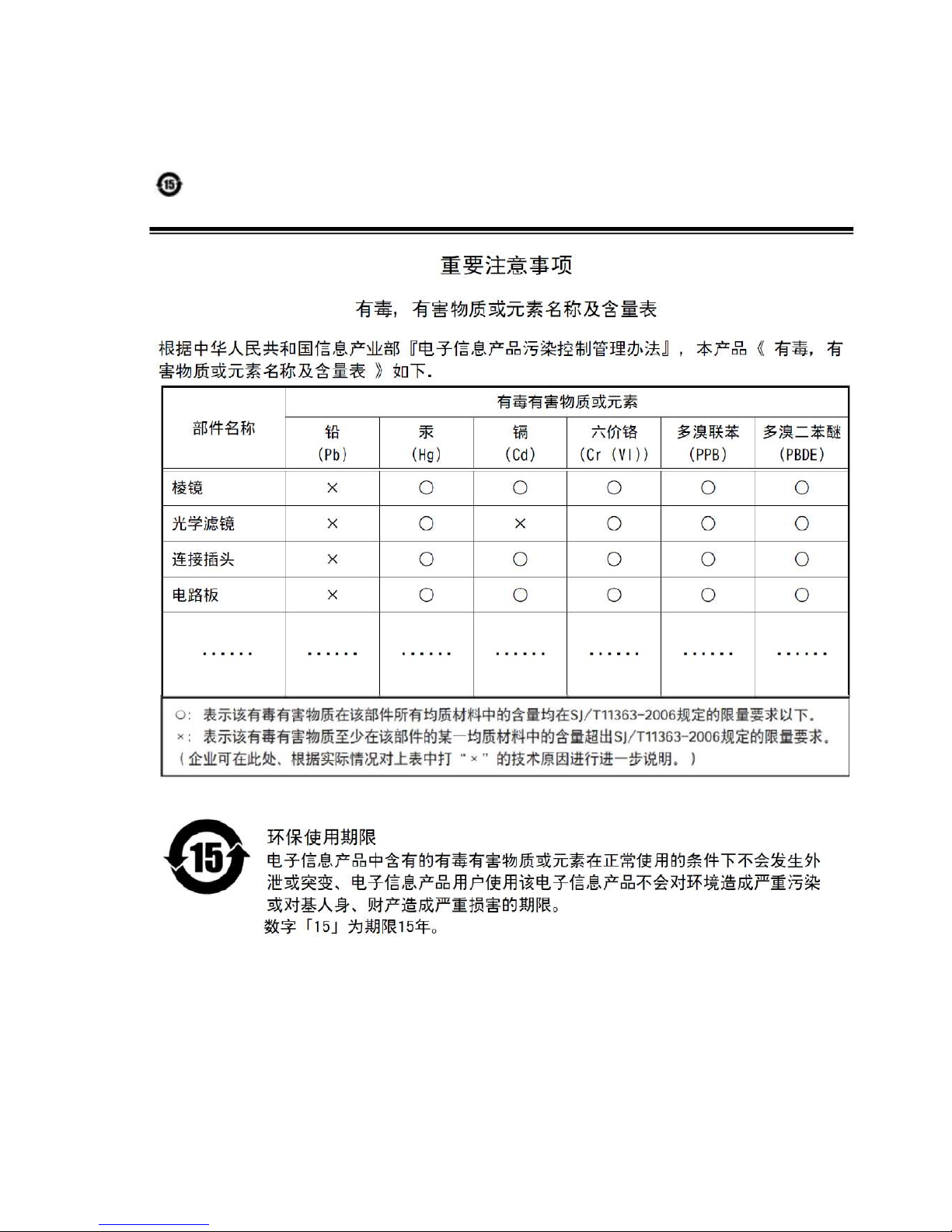
Supplement
The following statement is related to the regulation on “ Measures for the Administration
of the control of Pollution by Electronic Information Products “ , known as “ China RoHS “.
The table shows contained Hazardous Substances in this camera.
mark shows that the environment-friendly use period of contained Hazardous
Substances is 15 years.
Page 5

SP-12401M-PGE/SP-12401C-PGE
Usage Precautions
— 5 —
Notes on cable configurations
The presence of lighting equipment and television receivers nearby may result in
video noise. In such cases, change the cable configurations or placement.
Notes on LAN cable connection
Secure the locking screws on the connector manually,
and do not use a driver. Do not secure the screws too
tightly. Doing so may wear down the screw threads
on the camera. (Tightening torque: 0.147 Nm or less)
Notes on attaching the lens
Avoiding dust particles
When attaching the lens to the camera, stray dust and other particles may adhere
to the sensor surface and rear surface of the lens. Be careful of the following
when attaching the lens.
• Work in a clean environment.
• Do not remove the caps from the camera and lens until immediately before
you attach the lens.
• To prevent dust from adhering to surfaces, point the camera and lens
downward and do not allow the lens surface to come into contact with your
hands or other objects.
•
Always use a blower brush to remove any dust that adheres.
Never use your hands or cloth, blow with your mouth, or use other methods to
remove dust.
Phenomena specific to CMOS image sensors
The following phenomena are known to occur on cameras equipped with CMOS
image sensors. These do not indicate malfunctions.
• Aliasing
When shooting straight lines, stripes, and similar patterns, vertical aliasing
(zigzag distortion) may appear on the monitor.
• Blooming
When strong light enters the camera, some pixels on the CMOS image sensor
may receive much more light than they are designed to hold, causing the
accumulated signal charge to overflow into surrounding pixels.This
“blooming” phenomenon can be seen in the image, but does not affect the
operation of the camera.
• Fixed pattern noise
When shooting dark objects in high-temperature conditions, fixed pattern noise
may occur throughout the entire video monitor screen.
• Defective pixels
Defective pixels (white and black pixels) of the CMOS image sensor are
minimized at the factory according to shipping standards. However, as this
phenomenon can be affected by the ambient temperature, camera settings
(e.g., high sensitivity and long exposure), and other factors, be sure to operate
within the camera’s specified operating environment.
Notes on exportation
When exporting this product, please follow the export regulations of your country
or region.
Secure manually.
Do not secure too tightly.
Page 6
Features
SP-12401M-PGE/SP-12401C-PGE
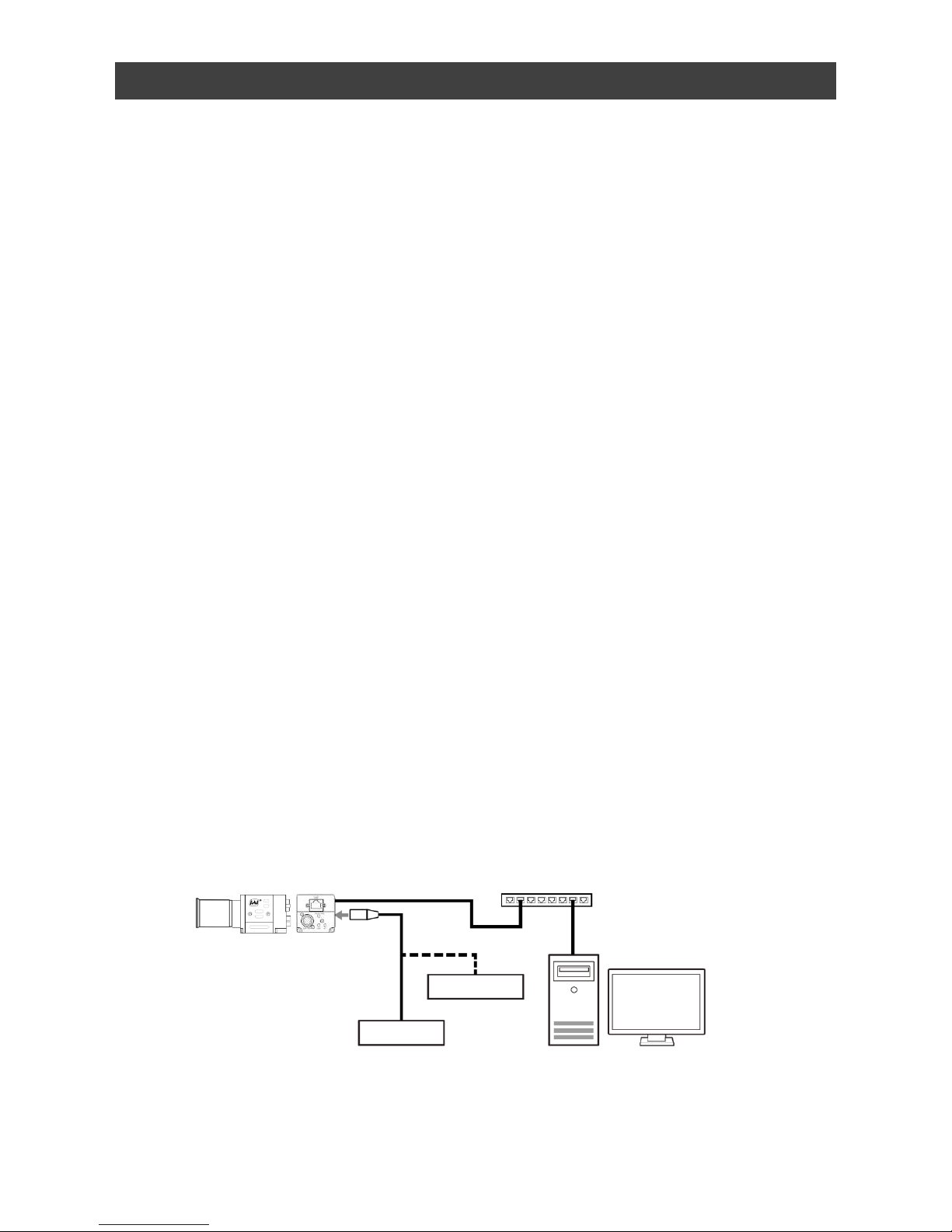
Connection example:
Camera
External Trigger
AC adapter
PoE-compatible switching hub
PC
— 6 —
The SP-12401M-PGE/SP-12401C-PGE is an industrial progressive scan camera equipped
with a 1.1-inch global shutter CMOS image sensor with 12.37 effective megapixels. The
SP-12401M-PGE/SP-12401C-PGE is part of JAI’s Spark Series, which provides an
attractive combination of high resolution, high speed, and high image quality for machine
vision applications.
This camera is equipped with various functions required for machine vision including
external trigger, exposure setting, image level control, look-up table, shading correction,
blemish compensation, ROI, binning, etc.
*) The SP-12401M-PGE produces monochrome output while the SP-12401C-PGE
produces Bayer output.
Feature overview
• Co
mpliance with GigE Vision and GenICam standards
• 1.1-inch 12.37 megapixel Global Shutter high resolution CMOS sensor
• Lens mount: C-mount (flange back: 17.526 mm)
• Pixel size : 3.45 um × 3.45 um
• Effective pixels SP-12401M-PGE (4112(H) x 3008(V)),
SP-12401C-PGE (4088(H) x 3000(V))
• Up to 9.3 fps at full resolution
• Various Video Output formats ( RGB format supported for color model )
SP-12401M-PGE : Mono8, Mono10, Mono10Packed, Mono12, Mono12Packed
SP-12401C-PGE : BayerRG8, BayerRG10, BayerRG10Packed, BayerRG12,
BayerRG12Packed, RGB8, RGB10V1Packed, RGB10p32
• Higher image quality by using 5x5 deBayer interpolation processing
( Only for RGB format output )
• Gamma correction circuit that uses lookup tables
• Col
or matrix that allows faithful color reproduction
• Col
or space conversion function (sRGB, Adobe RGB, HSI, XYZ support)
• In
ternal test signal for settings configuration
• eB
US SDK for JAI that supports Windows 7, 8, 10
Page 7
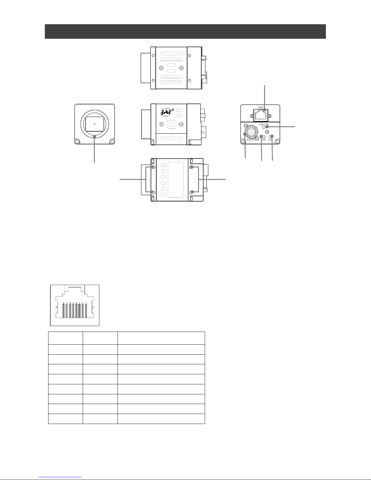
Parts Identification
SP-12401M-PGE/SP-12401C-PGE
① Lens mount(C-mount)
Mount a C-mount lens, microscope adapter, etc. here.
❖ B
efore mounting a lens, be sure to refer to “Step 2:Connecting Devices” and confirm
the precautions for attaching a lens and the supported lens types.
② RJ-45 connector
C
onnect a Gigabit Ethernet compatible LAN cable (Category 5e or higher, Category 6
recommended) here.
Pin No.
Input/
Output
Description
1 In/Out MX1+ (DA+)
2 In/Out MX1– (DA–)
3 In/Out MX2+ (DB+)
4 In/Out MX3+ (DC+)
5 In/Out MX3– (DC–)
6 In/Out MX2– (DB–)
7 In/Out MX4+ (DD+)
8 In/Out MX4– (DD–)
— 7 —
①
②
③
④⑤
⑥
⑦
⑦
Page 8
③ POWER/TRIG LED
Indi
cates the power and trigger input status.
LED status and camera status
LED Light Status
POWER/
TRIG LED
(Lit amber)
Camera initializing.
(Lit green)
Camera in operation.
(Blinking green
)
During operation in trigger mode, trigger signals are
being input.
❖ The blinking interval is not related to the actual input interval of
the external trigger.
SP-12401M-PGE/SP-12401C-PGE
④ ACT LED
Indicates the GigE network status.
⑤ LINK LE
D
Indicates whether the GigE network connection is established or not.
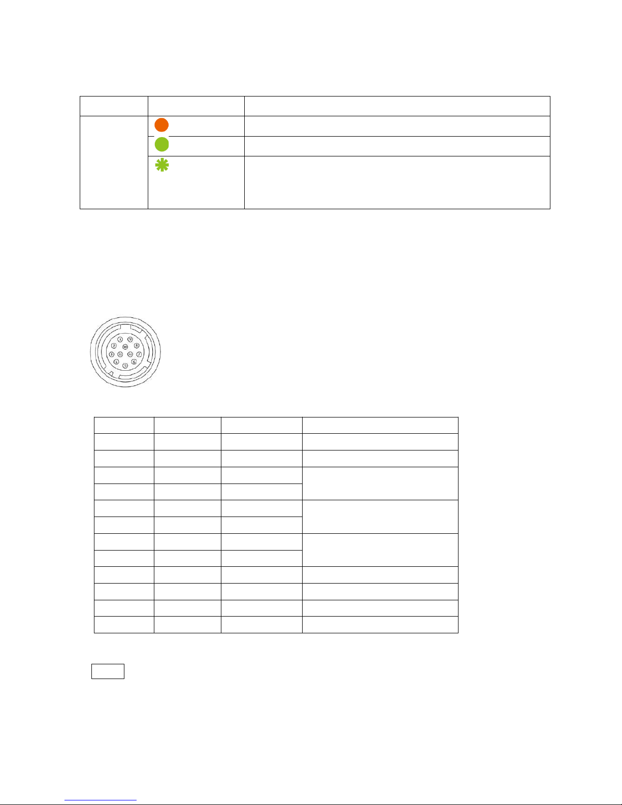
⑥ DC IN/
TRIG connector(12-pin round)
Conn
ect the cable for a power supply (optional) or for DC IN / trigger IN here.
HR10A-10R-12PB(71)(Hirose Electric or equivalent)
Pin No.
Input/Output
Signal Description
1
GND
2 Power
In DC In DC 12 V ~ 24 V ± 10%
3 In Opto In 2 -
Line 6
4 In Opto In 2 +
5 In Opto In 1 -
Line 5
6 In Opto In 1 +
7 Out Opto Out 1 -
Line 2
8 Out Opto Out 1 +
9 Out TTL Out 1 Line 1
10
11 Power In DC In DC 12 V ~ 24 V ± 10%
12
GND
Note
When DC power is supplied to either Pin 1/Pin 2 or Pin 11/Pin 12, the camera
operates.
— 8 —
Page 9
SP-12401M-PGE/SP-12401C-PGE
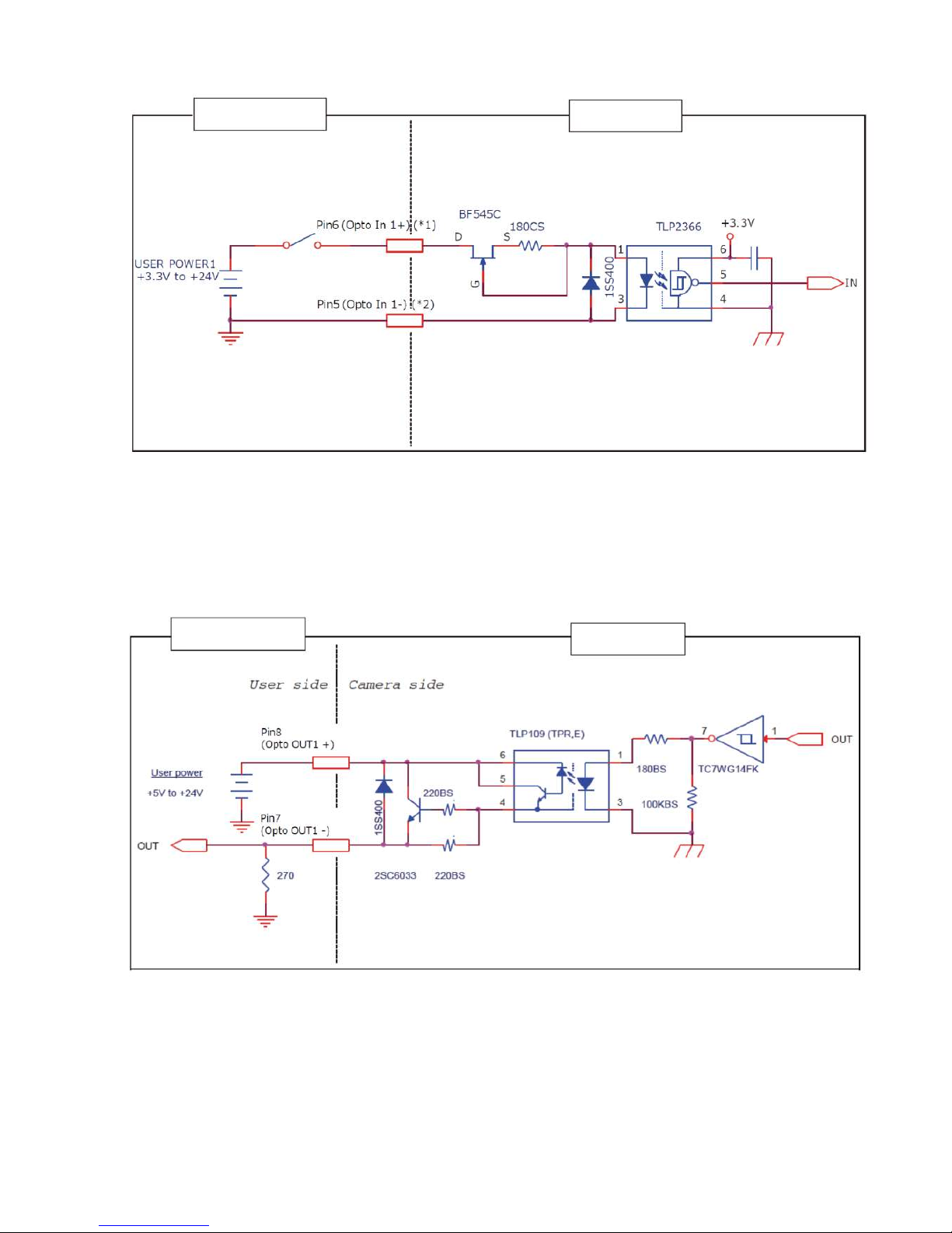
Recommended external input circuit diagram (reference example)
User Side
JAI Camera Side
User
side
CAMERA
side
When Opto In 2
(*1) Pin4 (Opto In 2+)
(*2) Pin3 (Opto In 2-)
Recommended external output circuit diagram (reference example)
Standard circuit diagram example
— 9 —
User Side
JAI Camera Side
Page 10
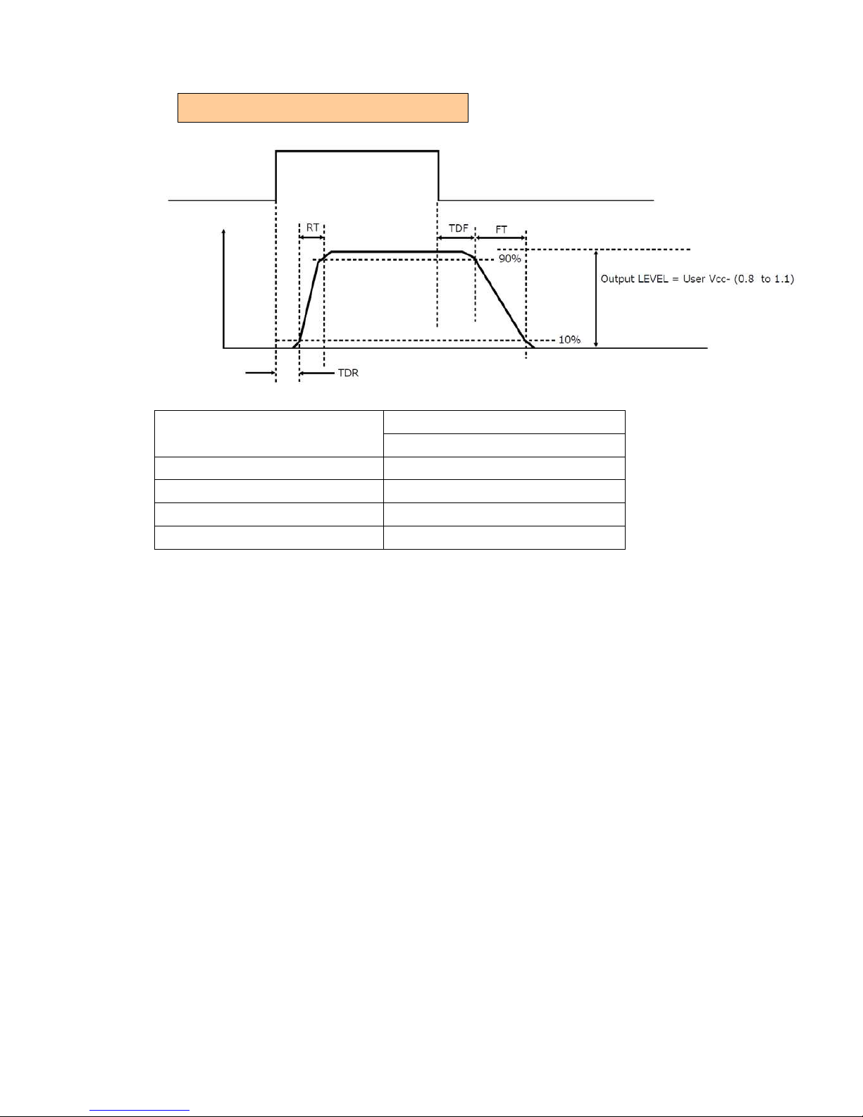
Characteristics of the recommended circuits for Opto OUT
OUTPUT LINE RESPONSE TIME
Camera
Output
Signal
Output
Line
Voltage
Us
er Power (VCC)
3.3 V ~ 24 V
Time Delay Rise TDR (us)
0.5 ~ 0.7
Tisc Time RT (us)
1.2 ~ 3.0
Time Delay Fall TDF (us)
1.5 ~ 3.0
Fall Time FT (us)
4 ~ 7
⑦ Camera locking screw holes(M3, 3
mm depth)
Use these holes when attaching an MP-45 tripod adapter plate (optional) or
mounting the camera directly to a wall or other structural system.
SP-12401M-PGE/SP-12401C-PGE
— 10 —
Page 11
SP-12401M-PGE/SP-12401C-PGE
Preparation
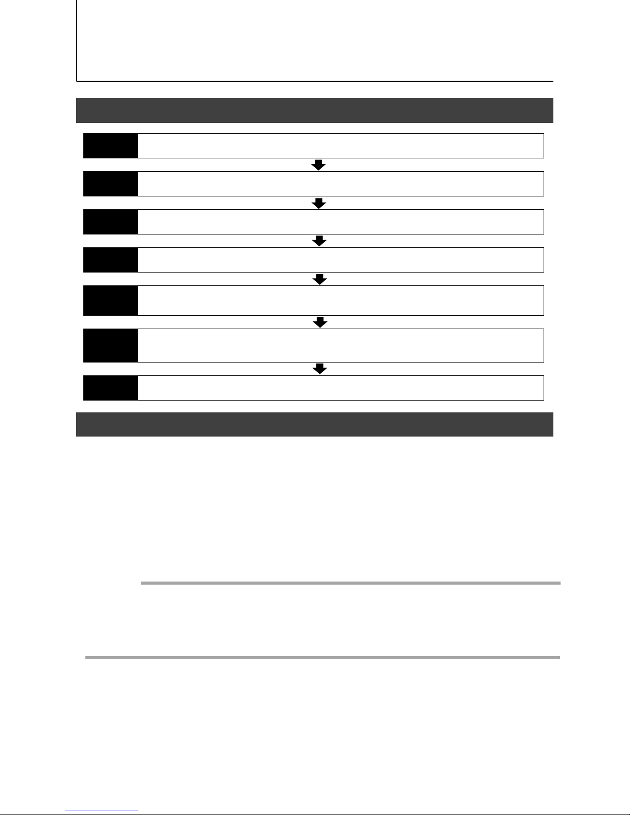
Preparation Process
Step 1
Installing the Software (first time only)
Install the software for configuring and controlling the camera (eBUS SDK for JAI) on the computer.
Step 2
Connecting Devices
Connect the lens, LAN cable, AC adapter, computer, and other devices.
Step 3
Verifying Camera Operation
Verify whether the camera is turned on and ready for use.
Step 4
Verifying the Connection between the Camera and PC
Verify whether the camera is properly recognized via Control Tool.
Step 5
Changing the Camera Settings
Refer to the procedure for changing the output format setting as an example, and change various
settings as necessary.
Step 6
Adjusting the Image Quality
Refer to the procedures for adjusting the gain, white balance, and black level as examples, and adjust
the image quality.
Step 7
Saving the Settings
Save the current setting configurations in user memory.
Step 1: Installing the Software (first time only)
— 11 —
When using the camera for the first time, install the software for configuring and
controlling the camera (eBUS SDK for JAI) on the computer.
❖ When you install eBUS SDK for JAI, eBUS SDK for JAI player will also be installed.
Download the eBUS SDK for JAI from the JAI website.
URL https://www.jai.com/support-software/jai-software
In
stall eBUS SDK for JAI on the computer.
Caution
eBUS SDK for JAI is software for setting and controlling the newly released camera in April
2018.
When JAI SDK and eBUS SDK for JAI are installed on the same machine, conflicts can
occur. Therefore, JAI strongly recommends that JAI SDK is uninstalled before installing
eBUS SDK for JAI.
1
2
Page 12
SP-12401M-PGE/SP-12401C-PGE
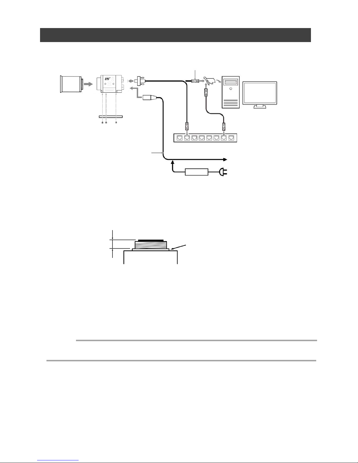
Step 2: Connecting Devices
①Lens
Cam
era body
③ LAN cable
② Di
rect connection
(or MP-45 tripod adapter plate)
(or
direct connection)
④ Network card
⑤ Computer
Sw
itching hub
⑥ DC IN/trigger IN
connection cable
or
⑦ AC adapter (not supplied)
① Lens
・C-mount lenses with lens mount protrusions of 9 mm or less can be attached.
Lens mount protrusion
Lens
9 mm or less
・The diagonal of the camera’s CMOS image sensor is 17.6 mm, the size of standard
1.1-inch lenses. To prevent vignetting and to obtain the optimal resolution, use a lens
that will cover the 17.6 mm diagonal. Some lens manufacturers offer lenses with
an 17.6 mm format. If not, a 1.1-inch lens is recommended.
— 12 —
To external trigger
・The maximum performance of the camera may not be realized depending on the lens.
・Attaching a lens with a mount protrusion of 9 mm or longer may damage the lens or camera.
Caution
Page 13

SP-12401M-PGE/SP-12401C-PGE
— 13 —
Note
The following formula can be used to estimate the focal length.
Focal length = WD /(1 + W/w)
WD :Working distance (distance between lens and object)
W :Width of object
w :Width of sensor(14.2 mm on this camera)
② Direct connection(or MP-45 tripod adapter plate)
When mounting the camera directly to a wall or other device, use screws that match the
camera locking screw holes on the camera (M3, depth: 3 mm). Use the supplied screws to
attach the tripod adapter plate.
For heavy lenses, be sure to support the lens itself. Do not use configurations in which its weight
is supported by the camera.
Caution
③ LAN cable
Connect a LAN cable to the RJ-45 connector.
• Use a LAN cable that is Category 5e or higher (Category 6 recommended).
• When supplying power via PoE, connect to a PoE-compatible switching hub or a PoE-compatible
network card.
•Refer to the specifications of the cable for details on its bend radius.
Se
cure the locking screws on the connector
manually, and do not use a driver. Do not secure
the screws too tightly. Doing so may wear down the
screw threads on the camera. (Tightening torque:
0.147 Nm or less)
Secure manually.
Do not secure too tightly.
④ Network card
Install this in the computer that will be used to configure and operate the camera. As the
SP-12401M-PGE and SP-12401C-PGE supports PoE, you can also use PoE-compatible
network cards. Refer to the instruction manual of the network card, and configure settings
on the computer as necessary.
⑤ Computer
Use a computer that meets the following requirements.
Operating system (OS):
Microsoft Windows 7/8/10 32-bit/64-bit edition
CPU: Intel Core i3 or higher
Memory:
Windows 7/8/10 32-bit edition: DDR3, 4 GB or higher
Windows 7/8/10 64-bit edition: DDR3, 8 GB or higher
Graphics card: PCI-Express 3.0 or higher
Network card: We recommend using a network card that uses an Intel chip.
Caution
Page 14
SP-12401M-PGE/SP-12401C-PGE
— 14 —
⑥ DC IN / trigger IN connection cable
⑦ AC adapter (power supply) (if necessary)
Connect the AC adapter and the round connector of the connection cable to the DC IN /
trigger IN connector on the camera.
Step 3: Verifying Camera Operation
When power is supplied to the camera while the necessary equipment is connected, the
POWER/TRIG LED at the rear of the camera lights amber, and initialization of the camera
starts.When initialization is complete, the POWER/TRIG LED lights green.
Verify whether power is being supplied to the camera by checking the rear LED.
When properly turned on
Lit green
* For details on how to read the LEDs, see “LED status and camera status” in the “Parts
Identification” section.
Step 4: Verifying the Connection between the Camera
and PC
Verify whether the camera is properly recognized via Control Tool.
Connecting the Camera to Control Tool
1
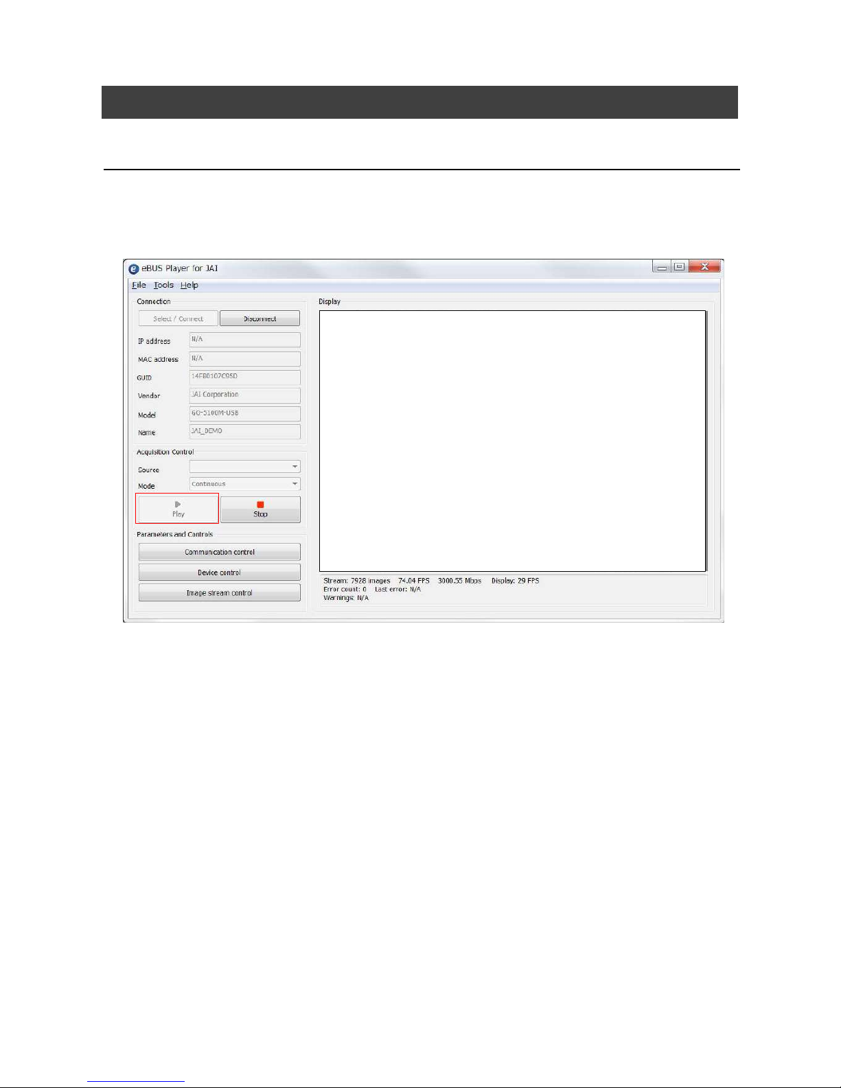
Startup eBUS Player for JAI
eB
US Player for JAI startup screen appears.
Page 15
SP-12401M-PGE/SP-12401C-PGE
— 15 —
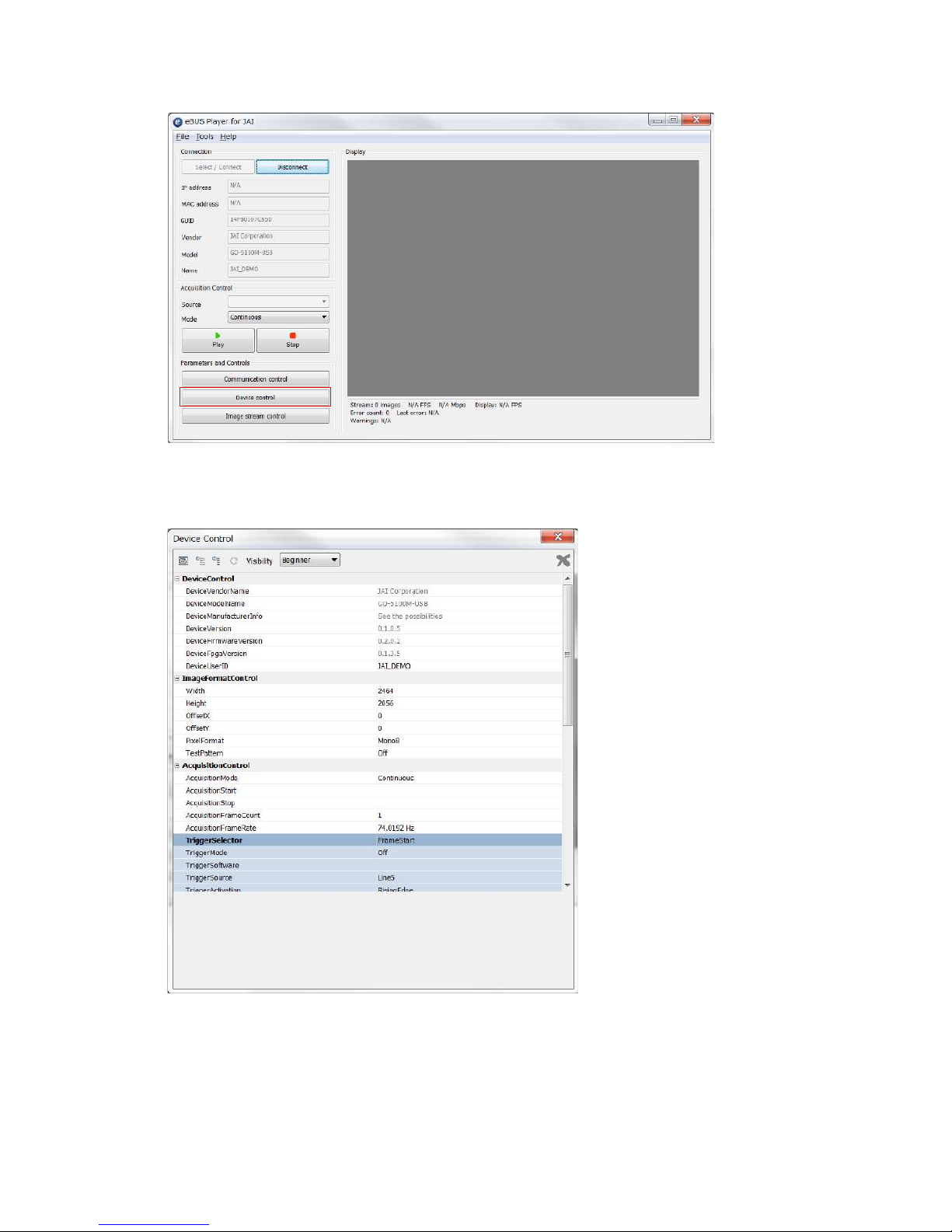
Push Select / Connect button
The connected camera is listed.
Please select one camera.
2
Select the camera you want to configure.
Page 16
SP-12401M-PGE/SP-12401C-PGE
— 16 —
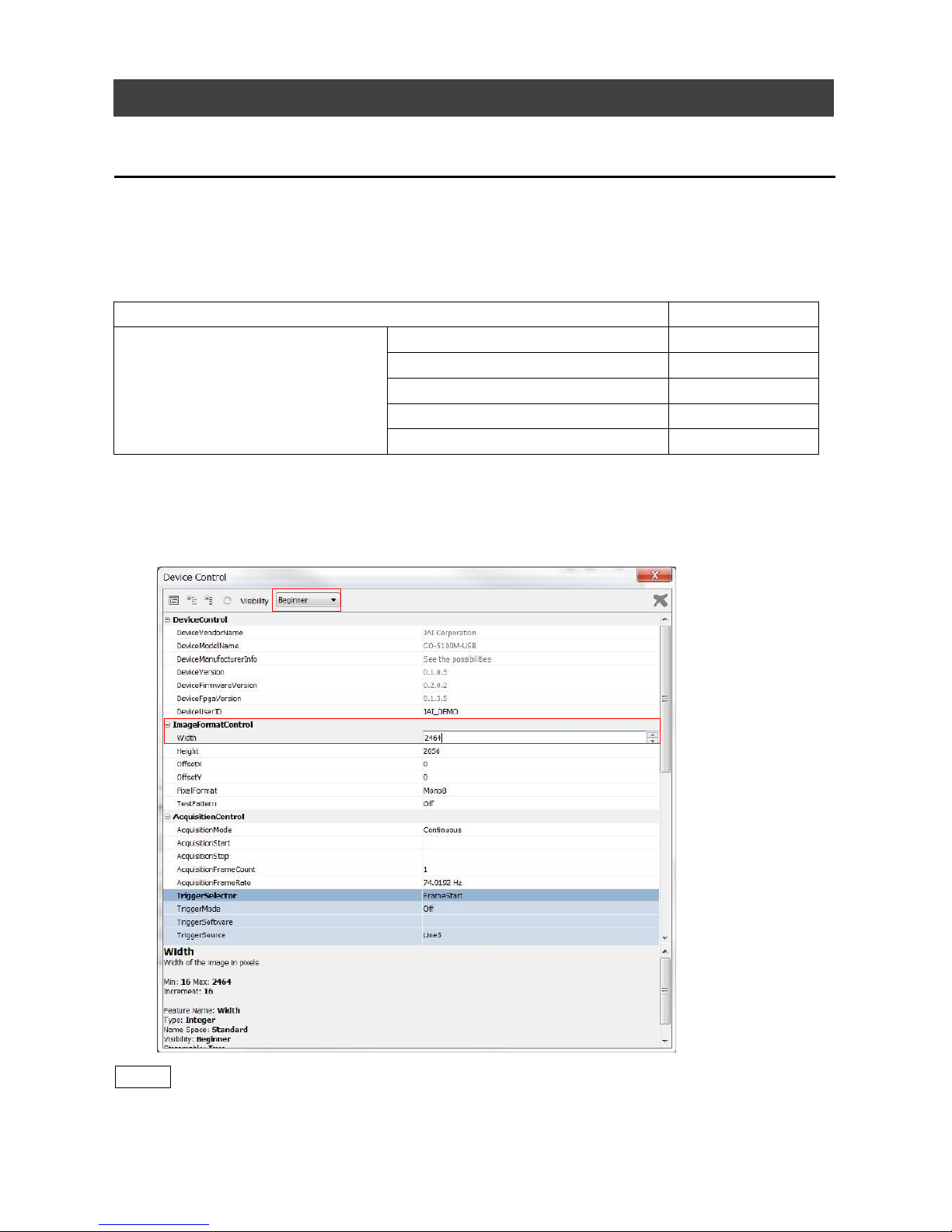
3
Check that the settings of the selected camera are displayed.
Push the Device control button.
The screen shown below will be displayed. In this window you can adjust various
settings of the camera.
This completes the procedure for verifying whether the camera is properly recognized and
whether control and settings configuration are possible.
Page 17
SP-12401M-PGE/SP-12401C-PGE
— 17 —
Step 5: Changing the Camera Settings
This section explains how to change settings by describing the procedure for changing the
output format as an example.
Configuring the Output Format
Configure the size, position, and pixel format of the images to be acquired.
The factory settings are as follows. Change the settings as necessary.
Factory default values (SP-12401C-PGE)
Item Default value
ImageFormatControl
Width 4088
Height 3000
OffsetX (horizontal position) 0
OffsetY (vertical position) 0
PixelFormat BayerRG8
* You can specify the image acquisition area. For details, see “ROI (Regional Scanning Function)”.
1
Configuring the [Width] of[ImageFormatControl]
By selecting the item of [Width], you can change the value as shown below.
Note
Depending on the setting item, you need to change visibility.
Please switch visibility (Beginner / Expert / Guru) as necessary.
Page 18
SP-12401M-PGE/SP-12401C-PGE
— 18 —
Step 6: Adjusting the Image Quality
Display the camera image and adjust the image quality.
Displaying the Image
Display the image captured by the camera.
When you push [Play] button, the camera image appears in right area.
Page 19

Adjusting the Gain
Adjust the image quality using the gain and white balance* functions.
*) SP-12401C-PGE only
SP-12401M-PGE/SP-12401C-PGE
— 19 —
To adjust the image quality
The Visibility must be changed from [Beginner] to [Guru].
Ad
just the sensitivity via the analog gain (i.e., master gain).
For details on gain control, see “Gain Control” in the “Main Functions” section.
■ Manual adjustment
1
Expand [AnalogControl], and set [GainAuto] to [Off].
([Off] is default setting.)
2
Configure the gain.
❶ Expand [AnalogControl], and select the gain you want to configure in [GainSelector].
[AnalogAll] (master gain), [DigitalRed]* (digital R gain), and [DigitalBlue]*
(digital B gain) can be configured.
❷ Conf
igure the gain value in [Gain].
• [AnalogAll] (master gain) can be set to a value from x1 to x16 the analog gain
value. The resolution is set in x0.1 steps. Values are configured by multipliers.
• The [DigitalRed]* (digital R gain) and [DigitalBlue]* (digital B gain) can be set to a
value from x0.447 to the [AnalogAll] (master gain) value.
Adjusting the White Balance*
Adjust the white balance using the automatic adjustment function.
*) SP-12401C-PGE only
■ Automatic white balance adjustment
1
Place a white sheet of paper or similar object under the same lighting conditions
as the intended subject, and zoom in to capture the white.
White objects near the subject, such as a white cloth or wall, can also be used. Be
sure to prevent the high-intensity spot lights from entering the screen.
2
Select the [BalanceWhiteAuto] tab, and select [Continuous] or [Once] for the
adjustment method.
The white balance is automatically adjusted.
Page 20
SP-12401M-PGE/SP-12401C-PGE
— 20 —
Adjusting the Black Level
1
Expand [AnalogControl], and select the black level you want to configure in
[BlackLevelSelector].
[DigitalAll] (master black), [DigitalRed]* (digital R), and [DigitalBlue]* (digital B) can
be configured.
2
Specify the adjustment value in [BlackLevel].
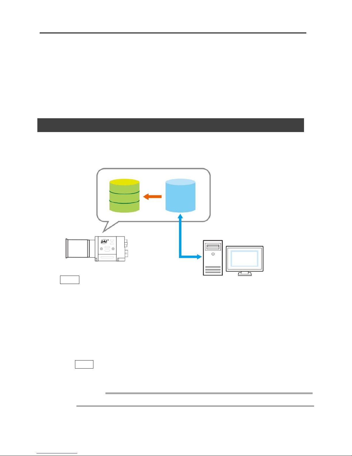
Step 7: Saving the Settings
The setting values configured in the player (eBUS SDK for JAI) will be deleted when the
camera is turned off. By saving current setting values to user memory, you can load and
recall them whenever necessary. You can save up to three sets of user settings in the
camera. (User Set1 to 3
eBUS SDK for
JAI (Player)
User memory
Temporary memory
Current
setting
save
User Set 1
User Set 2
User Set 3
Note
Changes to settings are not saved to the computer (eBUS SDK for JAI).
■ To save user settings
1
Stop image acquisition.
2
Expand [UserSetControl], and select the save destination ([UserSet1] to
[UserSet3]) in [UserSetSelector].
Note
The factory default setting values are stored in [Default] and cannot be overwritten.
Settings can only be saved when image acquisition on the camera is stopped.
Caution
*) SP-12401C-PGE only
Page 21

SP-12401M-PGE/SP-12401C-PGE
— 21 —
3
Select [UserSetSave], and click [Execute ‘UserSetSave’ Command].
The current setting values are saved as user settings.
■ To load user settings
1
Stop image acquisition.
User settings can only be loaded when image capture on the camera is stopped.
2
Select the settings to load (UserSet1 to UserSet3) in [UserSetSelector].
3
Select [UserSetLoad], and click [Execute ‘UserSetLoad’ Command].
The selected user settings are loaded.
Page 22
SP-12401M-PGE/SP-12401C-PGE
— 22 —
Main Functions
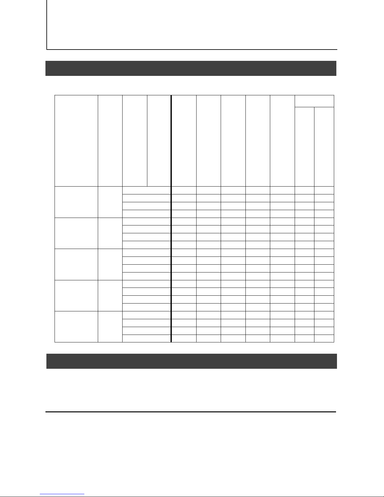
Basic Function Matrix
The combinations of settings for the basic functions that can be used together are as follows.
E
xposureMode
F
rameStartTrigger
B
inningVertical
B
inningHorizontal
ExposureTime
R
OI
B
alanceWhiteAuto
G
ainAuto
E
xposureAuto
Sequencer
Tr
iggerSequencerMode
CommandSequencerMode
Off
Off
1 x 1 (Off) × ○ ○ ○ × × ×
1 x 2 × ○ ○ ○ × × ×
2 x 1 × ○ ○ ○ × × ×
2 x 2 × ○ ○ ○ × × ×
Timed
Off
1 x 1 (Off) ○ ○ ○ ○ ○ × ○
1 x 2 ○ ○ ○ ○ ○ × ○
2 x 1 ○ ○ ○ ○ ○ × ○
2 x 2 ○ ○ ○ ○ ○ × ○
Timed(EPS) On
1 x 1 (Off) ○ ○ ○ ○ ○ ○ ○
1 x 2 ○ ○ ○ ○ ○ ○ ○
2 x 1 ○ ○ ○ ○ ○ ○ ○
2 x 2 ○ ○ ○ ○ ○ ○ ○
Timed(RCT) On
1 x 1 (Off) ○ ○ ○ ○ ○ ○ ○
1 x 2 ○ ○ ○ ○ ○ ○ ○
2 x 1 ○ ○ ○ ○ ○ ○ ○
2 x 2 ○ ○ ○ ○ ○ ○ ○
TriggerWidth On
1 x 1 (Off) × ○ ○ ○ × × ×
1 x 2 × ○ ○ ○ × × ×
2 x 1 × ○ ○ ○ × × ×
2 x 2 × ○ ○ ○ × × ×
GPIO (Digital Input/Output Settings)
The camera is equipped with GPIO (general-purpose input/output) functions for generating
and using combinations of triggers and other necessary signals within the camera and of
signals output from the camera to the system such as those used for lighting equipment
control.
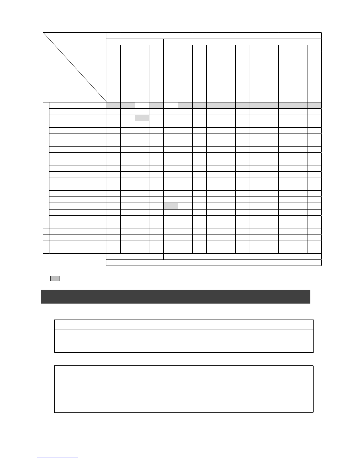
Valid Input/Output Combinations
The following signals can be used as sources for each output destination (Trigger Selector,
Line Selector, Pulse Generator Selector).
You can also connect two different sources to NAND paths in the GPIO and reuse the signal
generated there as a source for a different selector.
Page 23
SP-12401M-PGE/SP-12401C-PGE
— 23 —
The combinations of source signals and output destinations are indicated in the following.
Selector
(Cross point
switch output)
Source Signal
(Cross point switch input)
: Indicates default values for each selector.
Camera Output Formats
The SP-12401M-PGE supports the following output formats.
Low ○ ○ ○ ○ ○ ○ Off ○ ○ ○ ○ ○ ○ ○ ○
High ○ ○ ○ ○ ○ ○ × ○ ○ ○ ○ ○ ○ ○ ○
Line5-OptIn1 ○ ○ ○ ○ ○ ○ ○ ○ ○ ○ ○ ○ ○ ○ ○
Line6-OptIn2 ○ ○ ○ ○ ○ ○ ○ ○ ○ ○ ○ ○ ○ ○ ○
UserOutput0 ○ ○ ○ ○ ○ ○ ○ ○ ○ ○ ○ ○ ○ ○ ○
UserOutput1 ○ ○ ○ ○ ○ ○ ○ ○ ○ ○ ○ ○ ○ ○ ○
UserOutput2 ○ ○ ○ ○ ○ ○ ○ ○ ○ ○ ○ ○ ○ ○ ○
UserOutput3 ○ ○ ○ ○ ○ ○ ○ ○ ○ ○ ○ ○ ○ ○ ○
Action1 ○ ○ ○ ○ ○ ○ ○ × × ○ ○ ○ ○ ○ ○
Action2 ○ ○ ○ ○ ○ ○ ○ ○ ○ × × ○ ○ ○ ○
PulseGenerator0 ○ ○ ○ ○ ○ ○ ○ ○ ○ ○ ○ × ○ ○ ○
PulseGenerator1 ○ ○ ○ ○ ○ ○ ○ ○ ○ ○ ○ ○ × ○ ○
PulseGenerator2 ○ ○ ○ ○ ○ ○ ○ ○ ○ ○ ○ ○ ○ × ○
PulseGenerator3 ○ ○ ○ ○ ○ ○ ○ ○ ○ ○ ○ ○ ○ ○ ×
NAND0Out ○ ○ ○ ○ ○ ○ ○ × × ○ ○ ○ ○ ○ ○
NAND1Out ○ ○ ○ ○ ○ ○ ○ ○ ○ × × ○ ○ ○ ○
ExposureActive ー ー ー ー ○ ○ × ○ ○ ○ ○ ○ ○ ○ ○
AcquisitionActive ー ー ー ー ○ ○ × ○ ○ ○ ○ ○ ○ ○ ○
AcquisitionTriggerWait ー ー ー ー ○ ○ × ○ ○ ○ ○ ○ ○ ○ ○
FrameTriggerWait ー ー ー ー ○ ○ × ○ ○ ○ ○ ○ ○ ○ ○
FrameActi ve ー ー ー ー ○ ○ × ○ ○ ○ ○ ○ ○ ○ ○
FVAL ー ー ー ー ○ ○ × ○ ○ ○ ○ ○ ○ ○ ○
LVAL ー ー ー ー × × × × × × × ○ ○ ○ ○
Software ○ ○ ○ ○ ー ー ー ー ー ー ー ー ー ー ー
Output destination
Signals to use as output
NANDGate1In1
NANDGate1In2
PulseGenerator0
PulseGenerator1
PulseGenerator2
PulseGenerator3
TimestampReset
NANDGate0In1
NANDGate0In2
AcquisitionStart
Acquisi tionEnd
FrameStart
Acqui sitionTransferStart
TriggerSelector
PulseGeneratorSel ector
LineSelector
Use
TriggerSelector
LineSelector
PulseGeneratorSelector
Line1-TTLOut1
Line2-OptOut1
PixelFormat Available only VideoProcessBypassMode
Mono8, Mono10, Mono10Packed, Mono12,
Mono12Packed
Mono12, Mono12Packed
The SP-12401C-PGE supports the following output formats.
PixelFormat Available only VideoProcessBypassMode
BayerRG8, BayerRG10, BayerRG10Packed,
BayerRG12, BayerRG12Packed
RGB8,RGB10V1Packed,
RGB10p32
BayerRG12, BayerRG12Packed
Page 24
SP-12401M-PGE/SP-12401C-PGE
— 24 —
Image Acquisition Controls
Perform operations and configure settings related to image acquisition in [AcquisitionControl].
The following acquisition modes are available on the camera.
Changing the Frame Rate
When [TriggerMode] is disabled, you can change the frame rate in [AcquisitionFrameRate].
Note
• The shortest frame period varies depending on the ROI, pixel format, and binning mode
selected. The longest frame period is 0.125 Hz (8 sec.).
• When TriggerMode[FrameStart] is enabled, the [AcquisitionFrameRate] setting is disabled.
Maximum Frame Rate
The maximum frame rate is the smaller value between the SensorFR that is calculated from
the readable range of the sensor and the InterfaceFR that is limited by the GigE bandwidth.
Maximum frame rate
(Value derived from sensor
scanning range)
SensorFR
Maximum frame rate
(Value derived from GigE
bandwidth)
InterfaceFR
Compared
SensorFR > InterfaceFR
SensorFR < InterfaceFR
Maximum frame
SensorFR
Maximum frame
InterfaceFR
AcquisitionMode Description
SingleFrame
Acquire a single frame when the [AcquisitionStart]
command is executed.
MultiFrame
Acquire the number of frames specified in
[AcquisitionFrameCount] when the [AcquisitionStart]
command is executed.
Continuous
Acquire images continuously until the
[AcquisitionStop] command is executed.
Page 25

■ Maximum frame rate period formula
SP-12401M-PGE/SP-12401C-PGE
— 25 —
About the H_Period
Fo
r a full image, the H_period values are as follows for each PixelFormat.
Calculate the H_Period using the following formulas when cutting out a portion of the
image using ROI.
■ When [PixelFormat] is Mono8, Mono10Packed, Mono12Packed, Mono10 or Mono12.
GIGE
_H_Count_Max = ( Width / 2 + 32 )
Sensor_H_Count: 1041
■When [PixelFormat] is BayerRG8, BayerRG10Packed, BayerRG12Packed, BayerRG10
or BayerRG12.
GIGE_H_Count_Max = ( (Width + 8) / 2 + 32 )
Sensor_H_Count: 1041
■ When [PixelFormat] is RGB8, RGB10V1Packed or RGB10p32.
GIGE
_H_Count_Max = ( (Width + 8) / 2 + 32 )
Sensor_H_Count: 2082
H_Count = M
ax(Sensor_H_Count, GIGE_H_Count_Max)
H_Period = H_Count / PixelClock
PixelClock: 74.25 (MHz)
■ During continuous operation ([Frame Start] trigger is [Off] or [ExposureMode] is [Off])
PixelFormat H_period (us)
Mono8, Mono10, Mono12
Mono10Packed, Mono12Packed
28.121
BayerRG8, BayerRG10, BayerRG12
BayerRG10Packed, BayerRG12Packed
28.013
RGB8, RGB10V1Packed, RGB10p32 28.04
• Maximum frame rate of sensor output
SensorFR = 1 / ((Height_s + 36)×Hperiod)
• Maximum frame rate by interface
InterfaceFR = 920 × 1000000 / (Height_s × Width × Pack value)
Height_s : [SP-12401M-PGE]
When [VerticalBinning] is [1]. Height_s = Heigh
When [VerticalBinning] is [2]. Height_s = Height x 2
[SP-12401C-PGE]
Height_s = Height + 8
For a full image, the PackValue are as follows for each PixelFormat.
• Maximum frame rate
FR_Cont = Min (< SensorFR > , < InterfaceFR >)
• Exposure time possible within frames
MaxOverlapTime_longExp = (1 / FR_Cont) - (14 × H_Period)
• Exposure time outside of frame interval
NonOverlapExposureTime = ExposureTime - MaxOverlapTime_long
However, NonOverlapExposureTime_TrOloff calculation results that are 0 or below will be considered as 0.
For TriggerWidth, the trigger pulse is equivalent to ExposureTime.
• Maximum frame rate
FR_longExp = 1 / { (1 / FR_Cont) + NonOverlapExposureTime}
PixelFormat PackValue
Mono8/BayerRG8 8
Mono10Packed/Mono12Packed/
BayerRG10Packed/BayerRG12Packed
12
Mono10/Mono12/
BayerRG10/BayerRG12
16
RGB8 24
RGB10V1Packed/RGB10p32 32
Page 26

SP-12401M-PGE/SP-12401C-PGE
— 26 —
■ When [Frame Start] trigger is [On] and [TriggerOverLap] is [Off]
■ When [Frame Start] trigger is [On] and [TriggerOverLap] is [Readout]
ExposureMode
The following exposure modes are available on the camera.
* T h e settings for exposure control and triggers are related to each other. Be sure to configure the
settings described in “Trigger Control”.
ExposureMode Description
Off Exposure control is not performed (free-running operation).
Timed
Mode in which control is performed using exposure time. Acquire
images using an exposure time configured beforehand on an external
trigger.
TriggerWidth
Mode in which control of the exposure time is performed using the
pulse width of the trigger input signal. The exposure time will be the
same as the pulse width of the trigger input signal. This allows long
exposure.
• Maximum frame rate of sensor output
Sensor FR = 1 / {H Period × (Height_s + 36)}
• Maximum frame rate by interface
Interface FR = 920 × 1000000 / (Height×Width×Pack value)
• Maximum frame rate
FR_Cont = Min(< SensorFR > , < InterfaceFR >)
• Exposure time possible within frames
MaxOverlapTime_TrOloff = (1 / FR_Cont) - (1 / Sensor FR)
• Exposure time outside of frame interval
NonOverlapExposureTime_TrOloff = ExposureTime - MaxOverlapTime_TrOloff
However, NonOverlapExposureTime_TrOloff calculation results that are 0 or below will be considered as 0.
For TriggerWidth, the trigger pulse is equivalent to ExposureTime.
• Maximum frame rate
FR
_TrOloff = 1 / { (1 / FR_Cont) + NonOverlapExposureTime_TrOloff}
• M
aximum frame rate of sensor
Se
nsor FR = 1 / {H Period × (Height_s + 36)}
• Maximum frame rate by interface
Interface FR = 920 × 1000000 / (Height × Width × Pack value)
• Maximum frame rate
FR
_TrOloff = Min(Sensor FR, Interface FR)
• Exposure time possible within frames
Ma
xOverlapTime_TrOlrd = (1 / FR_Cont) - (14 × H_Period)
• Exposure time outside of frame interval
No
nOverlapExposureTime_TrOlrd = ExposureTime - MaxOverlapTime_TrOlrd
However, NonOverlapExposureTime_TrOlrd calculation results that are 0 or below will be considered as 0.
For TriggerWidth, the trigger pulse is equivalent to ExposureTime.
• Maximum frame rate
FR_TrOlrd = 1 / {(1 / FR_Cont) + NonOverlapExposureTime_TrOlrd}
Page 27

SP-12401M-PGE/SP-12401C-PGE
— 27 —
Actual Exposure Times
The shortest exposure times that can be configured are as follows.
・The actual exposure time will consist of the image sensor’s offset duration (14.26 μs) added
to the setting configured on the camera.
・When [ExposureMode] is set to [Timed] and the exposure time is set to 1 μs, the actual
exposure time will be as follows.
1 μs + 14.26 μs (offset duration of image sensor) = 15.26 μs
・When [ExposureMode] is set to [TriggerWidth], the exposure is slightly longer than the width
of the trigger signal. To achieve an exposure time of 15.26 µs and the exposure time offset
is 14.26 µs, use 15.26 µs - 14.26 µs = 1 µs as the high or low time for the trigger signal.
Trigger Control
The camera allows the following controls to be performed via external trigger signals.
• The settings for exposure control and triggers are related to each other. Be sure to
conf
igure the settings described in “ExposureMode” .
(1) You can delay when exposure actually starts after a trigger is received by a sp
ecific
amount of time by configuring [TriggerDelay].
ExposureMode Shortest exposure time
Timed 15.26us (8bit)
TriggerWidth 15.26us (8bit)
TriggerSelector Description
FrameStart
Start exposure in response to the external trigger signal input. Select
this to perform exposure control using external triggers.
AcquisitionStart Start image acquisition in response to the external trigger signal input.
AcquisitionEnd Stop image acquisition in response to the external trigger signal input.
AcquisitionTransferStart
Output acquired images at a specified timing in response to an
external trigger signal input.
* There is a limit to the number of image frames that can be stored
internally. The limits for each image format are as follows. Acquired
images must be output to avoid exceeding these limits.
8 bit: Up to 7 frames (RGB8: 4 frames)
10 bit: Up to 7 frames (RGB10V1Packed, RGB10p32: 4 frames)
12 bit: Up to 7 frames
BurstTriggerMode
In burst mode, continuous imaging is performed at a maximum speed of 23.4 fps, images are
temporarily stored in the memory, and data can be read later. Data reading is limited to the
speed of GigE Vision. Up to seven full images can be stored in the memory in the camera.
This function can be used by setting [ExposureModeOption] to [BurstTrigger].
*) SP-12401C-PGE
This function can not be used when PixelFormat is RGB8, RGB10V1Packed and
RGB10p32.
Page 28

SP-12401M-PGE/SP-12401C-PGE
— 28 —
Shortest Repetition Period for Triggers
The reciprocal of the maximum frame rate is the time required to output one frame. The
shortest repetition periods for triggers cannot be lower than that value.
The above table indicates the shortest trigger periods for when [TriggerOverLap] is set to
[Readout]. When [TriggerOverLap] is set to [Off], even when the exposure time is shorter
than the frame period, the cycle may be extended.
■ SP-12401M-PGE
■ SP-12401C-PGE
BayerRG8
BayerRG10,
BayerRG12
BayerRG10Packed,
BayerRG12Packed
RGB8
RGB10V1Packed,
RGB10p32
Full 106.6ms 213.2ms 160ms 319.5ms 427.4ms
ROI (Height = 1500) 53.3ms 106.6ms 80ms 160ms
213.2ms
ROI (Height = 750) 26.7ms 53.3ms 40ms 80ms 106.6ms
Scanning range
Shortest period of trigger
Mono8
Mono1 0,
Mono1 2
Mono1 0Packed,
Mono1 2Packed
Full 107.5ms 215.1ms 161.3ms
ROI (Height = 1500) 53.8ms 107.5ms 80.6ms
ROI (Height = 750) 26.9ms 53.8ms 40.3ms
BinningVertical2 53.8ms 107.5ms 80.6ms
Scanning range
Shortest period of trigger
Page 29

SP-12401M-PGE/SP-12401C-PGE
— 29 —
Next trigger disabled
Next trigger
Input enabled*
Trigger
CMOS
Exposure
Exposure
Active
■ When [ExposureMode] is [Timed]
Ex
ample: When [TriggerSource] is set to [Line 5 - OptIn1] and [OptInFilterSelector] is set
to [10 µs]
• Tr
iggerOverlap:Off
A
Exposure Time
B
Readout
//
PixelFormat Line Period (usec)
Period from Trigger
start edge to
Exposure start [A]
(usec)
Minimum Period
Exposure end to next
trigger start [B]
(usec)
Mono8 28.121 85.1 85906
Mono10Packed
Mono12Packed
28.121 85.1 85906
Mono10
Mono12
28.121 85.1 85906
BayerRG8 28.013 85.1
85900
BayerRG10Packed
BayerRG12Packed
28.013 85.1
85900
BayerRG10
BayerRG12
28.013 85.1
85900
RGB8 28.04 85.1
85896
RGB10V1Packed
RGB10p32
28.04 85.1
85896
*) If the exposure time is longer than the frame period excluding [B], the next trigger input
will not be accepted.
Page 30

SP-12401M-PGE/SP-12401C-PGE
— 30 —
• TriggerOverlap:readout
Next trigger disabled
Next trigger
Input enabled*
Trigger
CMOS
Exposure
Exposure
Active
A
Exposure Time
B
//
Readout
PixelFormat Line Period (usec)
Period from Trigger
start edge to
Exposure start [A]
(usec)
Minimum Period from
Exposure end to
next trigger
start[B](usec)
Mono8 28.121 85.1 282
Mono10Packed
Mono12Packed
28.121 85.1 282
Mono10
Mono12
28.121 85.1 282
BayerRG8 28.013 85.1 280
BayerRG10Packed
BayerRG12Packed
28.013 85.1 280
BayerRG10
BayerRG12
28.013 85.1 280
RGB8 28.04 85.1 280
RGB10V1Packed
RGB10p32
28.04 85.1 280
*) If the exposure time is longer than the frame period excluding [B], the next trigger input
will not be accepted.
Page 31

SP-12401M-PGE/SP-12401C-PGE
— 31 —
Next trigger disabled
Next trigger
input enabled*
Exposure Time
Trigger
CMOS
Exposure
Exposure
Active
■ When [ExposureMode] is [TriggerWidth]
Ex
ample: When [TriggerSource] is set to [Line 5 - Optical In 1] and [OptInFilterSelector]
is set to [10 µs]
• Tr
iggerOverlap:Off
A
B
//
C
Readout
PixelFormat Line Period (usec)
Period from Trigger
start edge to
Exposure start [A]
(usec)
Minimum Period
Exposure end to
next trigger
start[B](usec)
Period from
Trigger end edge
to Exposure
end[C] (usec)
Mono8 28.121 85.1 85906 85.1
Mono10Packed
Mono12Packed
28.121 85.1 85906 85.1
Mono10
Mono12
28.121 85.1 85906 85.1
BayerRG8 28.013 85.1 85900 85.1
BayerRG10Packed
BayerRG12Packed
28.013 85.1 85900 85.1
BayerRG10
BayerRG12
28.013 85.1 85900 85.1
RGB8 28.04 85.1 85896 85.1
RGB10V1Packed
RGB10p32
28.04 85.1 85896 85.1
*) If the exposure time is longer than the frame period excluding [B], the next trigger input
will not be accepted.
Page 32

• TriggerOverlap:readout
SP-12401M-PGE/SP-12401C-PGE
— 32 —
Next trigger
disabled
Next trigger
input enabled*
Exposure Time
Trigger
CMOS
Exposure
Exposure
Active
A
B
Readout
//
C
PixelFormat
Line Period
(usec)
Period from Trigger
start edge to
Exposure start [A]
(usec)
Minimum Period
Exposure end to
Next trigger
start[B]
(usec)
Period from Trigger
end edge to
Exposure end[C]
(usec)
Mono8 28.121 85.1 288 85.1
Mono10Packed
Mono12Packed
28.121 85.1 288 85.1
Mono10
Mono12
28.121 85.1 288 85.1
BayerRG8 28.013 85.1 288 85.1
BayerRG10Packed
BayerRG12Packed
28.013 85.1 288 85.1
BayerRG10
BayerRG12
28.013 85.1 288 85.1
RGB8 28.04 85.1 288 85.1
RGB10V1Packed
RGB10p32
28.04 85.1 288 85.1
*) If the exposure time is longer than the frame period excluding [B], the next trigger input
will not be accepted.
Page 33

SP-12401M-PGE/SP-12401C-PGE
— 33 —
Gain Control
Adjust the [AnalogAll] (master gain) setting first, and then adjust the [AnalogRed], [DigitalRed],
[AnalogBlue], and [DigitalBlue] setting values to perform fine adjustment.
*) Adjustment of
DigitalRed and DigitalBlue is possible only for SP-12401C-PGE
Analog All
Digital Red
Digital Blue
-7dB
-7dB
0dB
24dB
-7dB
15dB
-7dB
15dB
x 16
x 1.0
15dB
15dB
Automatic Gain Level Control
Set [GainAuto] to [Continuous] to control the gain level automatically.
When [GainAuto] is set to [Continuous], you can configure the conditions for automatic
adjustment in detail.
When [GainAuto] is set to [Continuous], automatic adjustment will be performed
continuously.
When [GainAuto] is set to [Once], automatic adjustment will be performed only once.
Description
Specify the target level for automatic gain control. (This setting
is also used for automatic exposure control.)
Select whether to specify all areas as auto gain metering areas
or whether to specify the areas individually.
[False]: Specify areas as auto gain metering areas (16 areas)
individually.[True]: Specify all areas as auto gain metering
areas.
Individually select any of 16 areas for automatic gain metering.
(This setting is also used for automatic exposure control.)
ALCAreaEnable
Select [True] to enable the metering area selected in
[ALCAreaSelector], or select [False] to disable it.
Specify the maximum value for the automatic gain control
range.
Specify the minimum value for the automatic gain control
range.
Specify the reaction speed for automatic gain control. (This
setting is also used for automatic exposure control.)
ALCControlSpeed
Item
ALCReference
ALCAreaEnableAll
ALCAreaSelector
AGCMax.
AGCMin.
Page 34

SP-12401M-PGE/SP-12401C-PGE
— 34 —
Auto gain metering areas (16 areas)
Lookup Table(LUT)
The LUT function is used to generate a non-linear mapping between signal values captured on
the sensor and those that are output from the camera. You can specify the output curve
using 257 setting points (indexes).
■ To use the LUT function
Configure the settings as follows.
■ LUT values
LU
T values range from 0 at the lowest to 4095 at the highest. Linear interpolation is used to
calculate LUT values between the index points.
Index0
Index1 Index2
LUTValue[0]
LUTValue[1]
LUTValue[2]
Index256
LUTValue[256]
0
4095
Values between points are determined
using the linear interpolation values of
data to the left and right.
Item
Setting value /
selectable range
Description
LUTMode LUT Use LUT.
LUTSelector* Red, Green, Blue Select the LUT channel to control.
LUTIndex 0 ~ 256
Select the LUT index to configure. Indexes represent the
possible pixel values captured on the sensor, from the
lowest value (In dex 0) to the high est (Index 2 56). For
example, Index 0 represents a full black pixel and Index
256 represents a full white pixel.
LUTValue 0 ~ 4095 Set the LUT output value for the selected index.
*) SP-12401C-PGE only
High
Left
High
Mid-left
High
Mid-right
High
Right
Mid-High
Left
Mid-High
Mid-left
Mid-High
Mid-right
Mid-High
Right
Mid-Low
Left
Mid-Low
Mid-left
Mid-Low
Mid-right
Mid-Low
Right
Low
Left
Low
Mid-left
Low
Mid-right
Low
Right
Page 35

SP-12401M-PGE/SP-12401C-PGE
— 35 —
Gamma Function
The gamma function corrects the output signals from the camera beforehand (reverse
correction), taking into consideration the light-emitting properties of the monitor display. As
the light-emitting properties of the monitor are not linear, the entire image may be darker or
the gradation in the dark areas may be less noticeable when camera outputs are displayed
without processing. The gamma function can be used to correct the camera signals with an
opposite-direction curve and produce a display that is close to linear.
0
0.2
0.4
0.6
0.8
1.0
1.2
Example of the light-emitting
properties of the monitor display
X
Y
Input ->
<- Output
■ To use the gamma function
Configure the settings as follows.
Note
You can use the LUT function to configure a curve with more detailed points. For details, see
“Lookup Table (LUT)”.
LineStatus
The line status function allows you to verify the status of external input/output signals. You
can verify the status of the following signals.
• Line5-OptIn1, Line6-OptIn2
• NANDGate0In1, NANDGate0In2
• NANDGate1In1, NANDGate1In2
• Line1-TTLOut1, Line2-OptOut1
• TimestampReset
Item
Setting value /
selectable range
Description
Gamma
0.45, 0.5, 0.55, 0.6, 0.65,
0.75, 0.8, 0.9, 1.0
Select the gamma correction value.
LUTMode Ga
mma Use gamma.
Page 36

SP-12401M-PGE/SP-12401C-PGE
— 36 —
BlemishCompensation
Multiple defective pixels that are not adjacent to each other can occur on conventional CMOS
sensor cameras.
This camera features a function that interpolates defective pixels using the surrounding pixels.
Up to 800 pixels can be corrected for each of the three sensors. Pixel interpolation can be
performed via automatic detection or point-by-point manual settings.
■ Automatic detection
Auto
matic detection can only detect lit defective pixels (i.e., white blemishes).
1
Shield the camera sensor.
If a lens is attached, use the lens cap as a shield, for example.
2
Configure the threshold level for defective pixel detection.
Up to 800 pixels can be corrected.
The threshold value is specified as a percentage.
The default setting is "10" with 10% of the full scale (100%) specified as the threshold
value.
3
Execute [BlemishDetect] to start automatic detection.
After detection, the interpolation data is saved to the camera's internal memory.
To check the number of interpolated pixels after automatic detection
You can check the number of pixels interpolated via automatic detection by loading the
BlemishNum data.
■ Manual configuration
1
Select the index in [BlemishCompensationIndex].
You can select from 1 to 800. However, configure the indexes in order starting
with the smallest index. If you skip indexes while configuring settings,
interpolation may not be performed.
2
Specify the pixel points for interpolation using the
[BlemishCompensationPositionX] and [BlemishCompensationPositionY] settings.
You can configure values that are within the total effective pixel area. Specify pixels for
which interpolation is not necessary as -1. If 0 is specified, the first line or first pixel
will be interpolated.
3
Execute [BlemishStore].
Blemish compensation data will be stored.
Note
BlemishCompensationDataClear[BlemishCompensationIndex], you can return a specific pixel
correction setting to the default value (storage not required).
4
Set [BlemishEnable] to [True], and execute interpolation.
If it is set to [False] , Blemish compensation is not effective.
Page 37

SP-12401M-PGE/SP-12401C-PGE
— 37 —
ShadingCorrection
The ShadingCorrection function corrects non-uniformity (i.e., shading) in the amount of light
generated by the lens and lighting equipment. Using this function allows correction even if top,
bottom, left, and right shading is not symmetrical in relation to the center of the screen (H, V).
This function can be used even when the effective image area is limited (an area with both
Width and Height set to more than 128 must be configured) by the ROI function. In such
cases, the correction area is included in the image area configured by the ROI.
SP-12401M-PGE
For a full image, the number of correction blocks is 17 (H) × 12 (V) blocks and calculation
errors in the correction data are minimized due to the small interpolation areas. Each block is
256 × 256 pixels. The total size of the blocks is 4352 (H)× 3072 (V), but the actual number of
effective pixels for the camera is 4112 (H) ×3008 (V) .The ineffective peripheral areas will be
deleted internally on the camera automatically.
SP-12401C-PGE
For a full image, the number of correction blocks is 16 (H) × 12 (V) blocks.
The total size of the blocks is 4096 (H) × 3072 (V).
The actual number of effective pixels for the camera is 4088 (H) x 3000 (V).
When using ROI, the number of blocks and the number of pixels that comprise each block
differ from a full image.
3072 (Total size)
3008 (Effective pixels)
4352 (Total size)
4112 (Effective pixels)
SP-12401M-PGE
Page 38

SP-12401M-PGE/SP-12401C-PGE
— 38 —
The following shading correction modes are available on the camera.
■ FlatShading
Cor
rection is performed using the area of the screen with the highest brightness level as the
reference, and adjusting the brightness levels of the other areas to match this level.
■ ColorShading (SP-12401C-PGE only)
R-cha
nnel and B-channel properties are adjusted to using the G-channel shading properties
as a reference.
Pre-correction
Post-correction
• For FlatShading and ColorShading, the maximum amount of correction gain for all pixels is
limited to 8 times the amount of gain before correction. (The amount of gain cannot be
increased to more than 8 times the amount of gain from before correction.)
• If the area in the screen with the highest brightness level is 175 LSB or less (during 10-bit
video output), proper correction is not possible.
Caution
■ To use the shading correction function
Configure the settings as follows.
Display a white chart under a uniform light, and execute [PerformShadingCalibration].
Note
After shading correction is executed, the shading correction value is automatically saved to the
user area selected in [ShadingMode].
Pre-correction
Post-correction
Item Setting value Description
ShadingCorrectionMode
FlatSh ading, ColorShading Select the shading correction mode.
ShadingMode User1, User2, User3 , Off
Select the user area to which to save the
shading correction value.
Page 39

SP-12401M-PGE/SP-12401C-PGE
— 39 —
Binning Function
(SP-12401M-PGE only)
The binning function allows you to combine the signal values of clusters of adjacent pixels to
create improved virtual pixels. Using the function results in images with lower pixel resolution
and higher sensitivity.
ROI (Regional Scanning Function)
The ROI (region of interest) function allows you to output images by specifying the areas to
scan.
ROI Settings
Specify the area to scan by specifying width, height, and horizontal/vertical offset values
under [ImageFormatControl].
For details on how to configure the settings, see “Configuring the Output Format”.
You can increase the frame rate by specifying a lower height, as the number of lines scanned
decreases.The setting ranges for the ROI function's readable area based on the Binning
setting (BinningHorizontal, BinningVertical) are as follows.
SP-12401M-PGE
SP-12401C-PGE
Width (pixels) Height (pixels)
BinningHorizontal Off:
16 to 4112, 8 pixels / step
BinningVerticall Off:
8 to 3008, 4 lines / step
BinningHorizontal On:
8 to 2056, 4 pixels / step
BinningVertical On:
8 to 1504, 2 lines / step
Width (pixels) Height (pixels)
16 to 4088, 8 pixels / step 8 to 3000, 4 lines / step
Offset X (pixels) Offset Y (pixels)
0 to 4072, 8 pixels / step 0 to 2992, 4 lines / step
Offset X (pixels) Offset Y (pixels)
BinningHorizontal Off:
0 to 4096, 8 pixels / step
BinningHorizontal Off:
0 to 3004, 4 lines / step
BinningHorizontal On:
0 to 2048, 4 pixels / step
BinningVertical On:
0 to 1500, 2 lines / step
Page 40

SP-12401M-PGE/SP-12401C-PGE
— 40 —
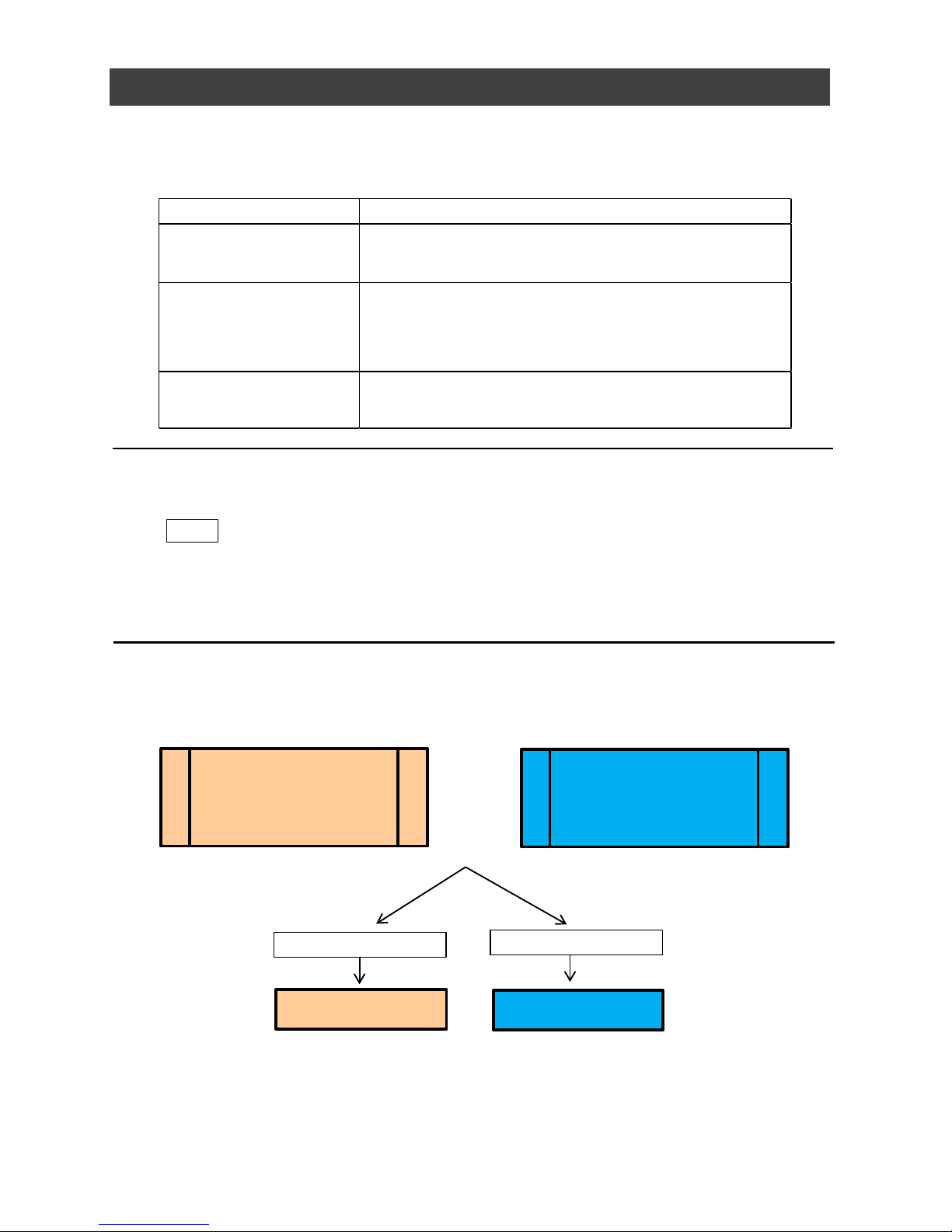
Example 1)Without Binning
[BinningHorizontal]
[BinningVertical]
Example 2)With Binning
[BinningHorizontal]
[BinningVertical]
:1
:1
:2
:2
4112 Width Max
3008 Height Max
2056 Width Max
1504 Height Max
* For details on the frame rates for common ROI sizes, see “Frame Rate Reference” .
Overlap Multi ROI Mode
In Overlap Multi ROI mode, you can specify up to five scanning areas (Index 1 to 5) for a
single-frame image. The areas can overlap, and a separate frame will be output for each area.
Scanning range
Scanning range
Page 41

SP-12401M-PGE/SP-12401C-PGE
— 41 —
Specify the areas by specifying width, height, and horizontal/vertical offset values for each
index under [JAICustomControlMultiROI].
Specify an ROI in the area scanned by
Sensor ROI and output as a separate
stream.
MultiROI Mode : On
Page 42

SP-12401M-PGE/SP-12401C-PGE
— 42 —
Trigger Sequencer mode
With this mode, the Sequencer Trigger “pattern” is predetermined by the user. The user
defines up to 128 different “indexes.” The items indicated in the above index can be
configured for each index. The operation of this mode is controlled using the following five
commands.
[SequencerSetActive]
This allows you to confirm the currently configured index number.
[SequencerSetStart]
This configures the index number to execute at the start of TriggerSequencer mode.
[SequencerLUTMode]
This defines whether to apply gamma or LUT to the sequence.When gamma is selected, the
gamma setting defined in [AnalogControl] is applied to all exposures in the sequence. When
LUT is selected, the LUT characteristics defined in [AnalogControl] are applied to indexes for
which [SequencerLUT enable] is set to ON.
[SequencerReset]
During TriggerSequencer mode operation, this switches the index number to be executed to
that specified in [SequencerSetStart].
[SequencerRepetition]
This parameter applies to TriggerSequencer patterns which include an index whose
[SequencerROINextIndex] is set to 0 (OFF).When the index whose [SequencerROINextIndex]
is set to 0 (OFF) is finished executing, the value of Sequencer Repetition (range = 1-255) is
decremented internally. If the result of the decrement is not zero, the TriggerSequencer
pattern starts over from the index specified in SequencerSetStart. If the result of the
decrement is zero, the status changes to Acquisition Stop and external triggers are not
accepted.
Sequencer Function
The Sequencer function lets you define up to 128 index combinations of exposure time, gain,
ROI, and other settings which can be stepped through each time a trigger is received.This is
particularly useful for quickly capturing multiple exposures of objects under inspection to adjust
for areas or components with significantly different levels of reflectance. You can specify the
next index in the stepping sequence and the order in which indexes are executed. Multiple
indexes can also be executed repeatedly.
Two operation modes (TriggerSequencer mode and CommandSequencer mode) are available
for the Sequencer function.
About indexes (imaging conditions)
Up to 128 indexes can be configured.The following settings can be configured for each
index. However, SequencerFrameNumber and SequencerSetNext can only be configured
in TriggerSequencer mode.
Note
Sequencer function can not be used with Overlap Multi ROI Function.
Page 43

SP-12401M-PGE/SP-12401C-PGE
— 43 —
Sample TriggerSequencer mode operation
User-defined Indexes (up to 128)
Triggers/
Image
Frames
1
Specify "1" in [SequencerSetStart], and start TriggerSequencer mode with index 1.
2
Capture a 2-frame image with the first and second triggers.
3
For the next index, configure index 3 specified in [SequencerSetNext], and capture
an image with the number of frames (number of triggers) specified in
[SequencerFrameNumber].
Proceed to sequence from index 4 to index 2 to index 1.
Note
In addition to repeating multiple conditions as in the above example, you can specify "0"
(which indicates the end of TriggerSequencer mode) in [SequencerSetNext] of index 2, and
specify the number of repetitions in [SequencerRepetition].
Command Sequencer mode
As with TriggerSequencer mode, you can define up to 128 indexes beforehand in this mode. Set
[SequencerCommandIndex] to point to one of your pre-configured indexes. This index will be
executed on each trigger, until it is changed to point to a different index, typically by your vision
application. In this way, Command Sequencer mode allows you to programmatically adjust your
sequence in response to image analysis or input from other sensors.
Note
• The same index table will be executed for subsequent triggers unless the
[CommandSequencerIndex] value is changed.
• [SequencerFrameNumber] and [SequencerSetNext] cannot be used in CommandSequencer
mode.
Page 44

SP-12401M-PGE/SP-12401C-PGE
— 44 —
Delayed Readout
Delayed readout allows images captured by a [FrameStart] trigger command to be stored
temporarily inside the camera (delayed readout buffer) and read out using a
[AcquisitionTransferStart] trigger after capture.This function is useful when executing triggers
simultaneously on multiple cameras.
Note
This function imposes a heavy processing load on the network bandwidth, as images from
multiple cameras are read out simultaneously. The number of frames that can be stored for
delayed readout depends on PixelFormat.
For details, see “Trigger Control” .
ALC (Automatic Level Control) Function
The ALC (automatic level control) function combines the automatic gain control (AGC/Auto
Gain Control) and automatic exposure control (ASC/Auto Shutter Control) functions, and is
capable of handling various changes in brightness.The function operates as follows in
response to changes in brightness.
Change from bright to dark: ASC → AGC
Change from dark to bright: AGC ASC
Change in brightness
Dark Bright
AGC operation
ASC (auto shutter) operation
AGC
Max
AGC operation
Max. to min. (user specified)
Fixed at min. gain value
ASC operation
Max. to min. (user specified)
Fixed at min. ASC value
Fixed at max. ASC value
Operation during change
from dark to bright
Operation during change
from bright to dark
■ To use the ALC function
Set [GainAuto] or [ExposureAuto] or both to [Continuous] mode. Configure the minimum value,
maximum value, etc. for AGC and ASC under [JAICustomControlALC].The target video levels
for AGC and ASC are configured in [ALCReference]. For example, when [ALCReference] is set
to 95%, video levels will be maintained at 95% for AGC and ASC.
Page 45

SP-12401M-PGE/SP-12401C-PGE
— 45 —
Color Space Conversion (ColorTransformationControl)
The SP-12401C-PGE model allows you to convert the standard color space (RGB) that is used
to produce colors into other color spaces, including XYZ and HSI.
Five color spaces are available: RGB(sRGB), RGB(AdobeRGB), RGB(UserCustom), XYZ, and
HSI. Specify the desied color space by configuring ColorTransofrmationMode and
ColorTransformationRGBMode as follows.
*) This function is valid only when PixelFormat is RGB8, RGB10V1Packed, RGB10p32.
■ Note
on RGB (UserCustom)
This
allows you to use user configured 3x3 conversion tables to perform color space conversion.
R in
G in
B in
RR RG RB
GR GG GB
BR BG BB
R out
G out
B out
Source data
3x3 table :
ColorMatrixValue[ColorMatrixValueSelector]
Destination data
If you set the color space to XYZ or HSI, JAI Control Tool will not display the images captured by
the camera properly. To display them properly, XYZ- or HSI-compatible image processing must
be performed on the computer side.
Caution
Configuration 3x3 table. Select the item you want to configure in [ColorMatrixValueSelector].
And configure the value in [ColorMatrixValue]. [ColorMatrixValue] can be set to a value from -2
to +2.
ColorTransformation ColorTransformationMode ColorTransformationRGBMode
RGB(
sRGB) RGB sRGB
RGB(AdobeRGB) RGB AdobeRGB
RGB( UserCustom) RGB UserCustom
XYZ XYZ Off
H S I H S I Off
Default RGB Off
Note
Color space (HSI)
Value of Hue : For 0°-360°, specify as follows.
8bit output: 2°/step 0°(00000000) ~ 360°(10110100)
10bit output: 0.5°/step 0°(0000000000) ~ 360°(1011010000)
12bit output: 0.125°/step 0°(000000000000) ~ 360°(101101000000)
Value of Saturation, Intensity: For 0% - 100
%, specify as follows.
8bit output: 0%(00000000) ~ 100%(11111111)
10bit output : 0%(00000000) ~ 100%(1111111111)
12bit output : 0%(00000000) ~ 100%(111111111111)
Setting value Description
ColorMatrixValueSelector
ColorMatrixR-R, ColorMatrixR-G, ColorMatrixR-B,
ColorMatrixG-R, ColorMatrixG-G, ColorMatrixG-B,
ColorMatrixB-R, ColorMatrixB-G, ColorMatrixB-B
Select the ColorMatrix setting
component.
ColorMatrixValue -2 to 2 Set the Color Matrix valu e.
Item
Page 46

SP-12401M-PGE/SP-12401C-PGE
— 46 —
Edge Enhancer, Color Enhancer
This camera is equipped with an edge enhancer function for enhancing the contrast of lines or
edges within images and a color enhancer function for enhancing specified colors.
Edge enhancer function
The edge enhancer function is enabled when EnhancerEnable[Edge] is set to True. Four
enhancement levels are available: Low, Middle, High, and Strong.
*) For SP-12401C-PGE, This function is valid only when PixelFormat is RGB8,
RGB10V1Packed, RGB10p32.
Color enhancer function (SP-12401C-PGE only)
The color enhancer function is enabled when EnhancerEnable[Color] is set to True. Set a
value from 0 to 1 (0.1 steps) for ColorEnhancerValue[ColorEnhancerSelector] to set the
enhancement to one of ten levels (0: no enhancement; 1: approx. x2 the color level of the
original data) Six colors can be specified in ColorEnhancerSelector: Red, Cyan, Green,
Magenta, Blue, and Yellow.
*) This function is valid only when PixelFormat is RGB8, RGB10V1Packed, RGB10p32.
CounterAndTimerControl Function
This camera supports only the counter function.
The counter function counts up change points in the camera’s internal signals using the
camera’s internal counter, and reads that information from the host side. This function is
useful for verifying error conditions via the count value using internal camera operations.
Four counters are available on the camera; Counter0, Counter1, Counter2, and Counter3.
The functions that can be counted are fixed for each counter.
Counter0: Counts the number of FrameStartTrigger instances.
Counter1: Counts the number of ExposureStart instances.
Counter2: Counts the number of SensorReadOut instances.
Counter3: Counts the number of FrameTransferEnd instances.
When a problem occurs in a system that includes this camera, comparing the values from
multiple counters allows you to verify the extent of normal operability and can be useful when
investigating the cause of the problem.
■ Counter occurrence diagram
FrameStartTrigger
Counter0
ExposureStart
Counter1
Event occurrence
Count up
Counter0
Request
Read out
value
Counter reset
Count up
Counter1
Request
Read count
value
Counter reset
Count 0 reset
Counter1 reset
MCU
HOST
Note
You can reset a specific counter's count value by executing CounterReset[Counter0, Counter1,
Counter2, Counter3].
Event occurrence
Page 47

SP-12401M-PGE/SP-12401C-PGE
— 47 —
■ Internal camera blocks
Counter0
FrameStartTrigger
Counter1
ExposureStart
Counter2
SensorReadOut
Counter3
FrameTransferEnd
Event detection
Counter
At event occ urrence or count up
Counter
At event occ urrence or count up
Counter
At event occ urrence or count up
Counter
At event occ urrence or count up
Counter reset
Read requested counter value
Internal MCU of camera
Send information
to the HOST
■ To use the counter function
Conf
igure the settings as follows.
Four counters are available. Specify a counter (Counter0 to Counter3), and configure the
settings.
Event detection
Event detection
Event detection
Setting value /
selectable range
Description
Counter 0 ~ 3 Select the counter.
CounterEventSource
Counter0
Off, Frame Trigger
Counter1
Off, ExposureStart
Counter2
Off, SensorReadOut
Counter3
Off, FrameTransferEnd
Select the counter event signal
for which to read the count
value.
When set to Off, the counter
operation will stop (but will not
be reset).
CounterEventActivation
When the counter function is
enabled, Counter0, Counter1,
and Counter2 are fixed at
RisingEdge. Counter3 is fixed
at FallingEdge.
Specify the timing at which to
count.
Item
Counter 0 ~ 3
Page 48

SP-12401M-PGE/SP-12401C-PGE
— 48 —
VideoProcessBypassMode
The video process bypass mode is a function that bypasses internal video processing on the
camera. When bypass is enabled, the sensor output and camera output data can be set to the
same bit width.
12-bit outputs can only be performed in bypass mode.
The
following functions can be used in video process bypass mode.
Gain[AnalogAll], Gain[AnalogRed], Gain[AnalogGreen], Gain[AnalogBlue],
Au
toGainControl, AutoShutterControl, AutoWhiteBalance, SequencerMode,
B
lemishCompensation
■ Functions available in VideoProcessBypassMode
Chunk Data Function
The Chunk Data function adds camera configuration information to the image data that is
output from the camera. Embedding camera configuration information in the image data
allows you to use the serial number of the camera as a search key and find specific image data
from among large volumes of image data. In addition, when images are shot with a single
camera in sequence under multiple setting conditions, you can search for images by their
setting conditions.
The following information can be added to image data as chunk data.
■ Configuring Chunk Data
1
Set [ChunkModeActive] to [True].
2
Select the items of information you want added to image data with
[ChunkSelector], and set [ChunkEnable] from [False] to [True].
The Chunk Data function settings cannot be changed during image output. To change the
settings, stop Acquisition.
Caution
Note
When [ChunkModeActive] is set to [True], [ChunkImage] is automatically set to [True].
VideoProcessBypassMode On Off
Camera operation
The following f unc tions will be
disabled, regardless of th eir
configurations.
Gain[DigitalRed],
Gain[DigitalBlue] ,
BlackLevel,
LUT,
Shading,
Binnin g(H,V),
Enhancement,
ColorMatrix
All video processes are enabled.
Camera output
(PixelFormat)
The following f ormat will be
availabled.
Mono8,Mono1 0, Mono10Packed,
BayerRG8, BayerRG10,
BayerRG10 Packed,
RGB8,RGB10V1Packed,
RGB10p32,
Mono12,Mon o12Packed,
BayerRG12, BayerRG12Packed,
The following f ormat will be
availabled.
Mono8,Mono1 0, Mono10Packed,
BayerRG8, BayerRG10,
BayerRG10 Packed,
RGB8,RGB10V1Packed,
RGB10p32,
*) For items that can be added to image data as Chunk Data, refer to [m) ChunkDataControl]
in the setting item list.
Page 49

— 49 —
Event Control Function
The Event Control Function is a function that outputs a signal change point inside the camera
as information indicative of an event occurrence (event message) by using GVCP (GigE Vision
Control Protocol).
■ Events that can use the Event Control Function
Events that can use the Event Control Function are as follows. You can specify whether or not
to send an event message when an event occurs at each event.
Acq
uisitionTrigger,
FrameStart,
FrameEnd,
FVALStart,
FVALEnd,
ExposureStartRed,
ExposureEndRed,
Line1-TTLOut1-RisingEdge,
Line1-TTLOut1-FallingEdge,
Line2-OptOut1-RisingEdge,
Line2-OptOut1-FallingEdge,
Line5-OptIn1-RisingEdge,
Line5-OptIn1-FallingEdge,
Line6-OptIn2-RisingEdge,
Line6-OptIn2-FallingEdge,
SP-12401M-PGE/SP-12401C-PGE
Detect an event
Keep the event type and
timestamp value when an event
occurs.
Interrupt signal
Event signal
Send an event message
MCU inside the camera
Reset event information after an
event message has been sent
■ Flow from detecting an event to sending an event message
Page 50

— 50 —
Action Control Function
The Action Control Function is a function that executes the pre-configured action when the
camera receives action commands. Action commands can send both unicast and broadcast
messages and give instructions for actions to multiple cameras simultaneously by broadcasting
them. A camera that has this function can even give instructions for actions to different types
of multiple cameras. Although this function includes jitter and delays, it is useful for controlling
multiple cameras simultaneously.
Actions are performed when the following three conditions are met.
1. ActionDeviceKey set to the camera and ActionDeviceKey in the action command ma
tch
2. ActionGroupKey set to the camera and ActionGroupKey in the action command match
3. ActionGroupMask se
t to the camera and GroupMask in the action command perform AND
operation, and the result is not 0.
SP-12401M-PGE/SP-12401C-PGE
■ About the settings of the camera
1. Specify ActionDeviceKey.
2. Then, specify two actions that can be configured on the camera.
Act
ion1
Select 1 in ActionSelector.
Specify ActionGroupMask [ActionSelector].
Specify ActionGroupKey [ActionSelector].
Action2
Select 2 in ActionSelector.
Specify ActionGroupMask [ActionSelector].
Specify ActionGroupKey [ActionSelector].
3. Set triggers (AcquisitionStart, AcquisitionEnd, FrameStart, AcquisitionTransferStart) to
Act
ion1 and Action2.
■ Setting example
Assume that the following settings have been pre-configured on the camera.
ActionDeviceKey : 0x00001001
ActionGroupMask[1] : 0x00000011
ActionGroupKey[1] : 0x00000001
ActionGroupMask[2] : 0x00000111
ActionGroupKey[2] : 0x00000002
When the camera receives action commands (ActionDeviceKey:0x00001001, ActionGroupMask:0x00000011,
ActionGroupKey: 0x00000002), Action2 is executed.
When the camera receives action commands (ActionDeviceKey:0x00001001, ActionGroupMask:0x00000011,
Acti
onGroupKey: 0x00000001), ActionDevice and ActionGroupKey[1] match. However, the result of AND operation
performed by ActionGroupMask is 0. Therefore, in this case, neither Action1 nor Action2 is executed.
Page 51

SP-12401M-PGE/SP-12401C-PGE
— 51 —
Setting List
Feature Properties
Setting range Default value Description
Display/configure information related to
the device.
ー "JAI Corporation" Display the manufacturer name.
ー SP-12401M-PGE/
SP-12401C-PGE
Display the model name.
ー See the possibilities Display the manufacturer information.
ー ー Display the hardware version.
ー ー Display the firmware version.
ー ー Display the device ID.
Any ー Set the user ID (16bytes) for the camera.
Mainboard Mainboard Select the area of the camera's interior for
which to display the temperature sensor's
reading. (fixed Mainboard)
DeviceTemperature(C) ー ー Display the internal temperature (°C) of
the camera.
ー
0~
9223372036854775807
(maximum value of
signed 64-bit)
Display the timestamp value. Resets to 0
when the signed maximum 64-bit value is
exceeded.
ー ー Forcibly sets the timestamp's count value
to 0.
ーー
0~9223372036854775807
(maximum value of signed
64-bit)
0
ー ー Reset the device.
(After the camera receives this command,
it returns an ACK response. Then, execute
reset.)
Configure image format settings.
4112 4112 Display the maximum image width.
3008 3008 Display the maximum image height.
12 Bits 12 Bits Display the number of bits at which the
sensor is operating.
SP-12401M-PGE
BinningHorizontal 1:
4112
BinningHorizontal 2:
2056
SP-12401C-PGE
4088
SP-12401M-PGE
BinningHorizontal 1:
4112
BinningHorizontal 2:
2056
SP-12401C-PGE
4088
Display the maximum image width.
(The values are different between SP-12401M-PGE
and SP-12401C-PGE.)
(SP-12401M-PGE : This value will vary depending on
the HorizontalBinning setting.)
SP-12401M-PGE
BinningVertical 1:
3008
BinningVertical 1:
1504
SP-12401C-PGE
3000
SP-12401M-PGE
BinningVertical 1:
3008
BinningVertical 1:
1504
SP-12401C-PGE
3000
Display the maximum image height.
(The values are different between SP-12401M-PGE
and SP-12401C-PGE.)
(SP-12401M-PGE : This value will vary depending on
the VerticalBinning setting.)
Sets the timestamp's count value to
TimestampLatchValue.
Timestamp (ns)
SensorWidth
SensorHeight
SensorDigitizationBits
WidthMax
HeightMax
b)) ImageFormatContr
DeviceReset
TimestampLatchValue (ns)
TimestampLatch
TimestampReset
F
DeviceVendorName
DeviceModelName
DeviceManufacturerInfo
DeviceVersion
DeviceFirmwareVersion
DeviceSerialNumber
DeviceUserID
DeviceTemperatureSelector
a)) DeviceContr
Page 52

SP-12401M-PGE
BinningHorizontal 1:
16~4112 step 8
BinningHorizontal 2:
8~2056 step 4
SP-12401C-PGE
16~4088 step 8
SP-12401M-PGE
BinningHorizontal 1:
4112
BinningHorizontal 2:
2056
SP-12401C-PGE
4088
Set the image width.
SP-12401M-PGE
BinningVertical 1:
8 ~ 3008 step 2
BinningVertical 1:
8 ~ 1504 step 2
SP-12401C-PGE
8 ~ 3000 step 2
SP-12401M-PGE
BinningVertical 1:
3008
BinningVertical 1:
1504
SP-12401C-PGE
3000
Set the image height.
SP-12401M-PGE
BinningVertical 1:
0 ~ 4096 step 8
BinningVertical 2:
0 ~ 2048 step 4
SP-12401C-PGE
0 ~ 4072 step 8
0 Set the horizontal offset.
SP-12401M-PGE
BinningVertical 1:
0 ~ 3000 step 4
BinningVertical 2:
0 ~ 1496 step 2
SP-12401C-PGE
0 ~ 2992 step 4
0 Set the vertical offset.
Average, Sum Sum Set the addition process to be used during
horizontal binning.
(SP-12401M-PGE only)
1,2 1 Set the number of pixels in the horizontal
direction for which to perform binning.
(SP-12401M-PGE only)
Average, Sum Sum Display the addition process to be used
during vertical binning.
(SP-12401M-PGE only)
1,2 1 Set the number of pixels in the vertical
direction for which to perform binning.
(SP-12401M-PGE only)
SP-12401M-PGE
Mono8,
Mono10, Mono10Packed,
Mono12,
Mono12Packed
SP-12401C-PGE
BayerRG8,
BayerRG10,
BayerRG10Packed,
BayerRG12,
BayerRG12Packed
RGB8,
RGB10V1Packed,
RGB10p32
SP-12401M-PGE
Mono8
SP-12401C-PGE
BayerRG8
Set the pixel format.
The following mode are enabled when
[VideoProcessBypassMode] is set to [On].
SP-12401M-PGE
Mono12, Mono12Packed
SP-12401M-PGE
BayerRG12, BayerRG12Packed
PixelFormat
Width
BinningVertical
BinningVerticalMode
BinningHorizontal
BinningHorizontalMode
OffsetY
OffsetX
Height
SP-12401M-PGE/SP-12401C-PGE
— 52 —
Page 53

Off,
GreyHorizontalRamp,
GreyVerticalRamp,
GreyHorizontalRampMoving,
以下 SP-12041C-PGEのみ
HorizontalColorBar,
VerticalColorBar,
HorizontalColorBarMoving
Off Select the test image.
Configure image capture settings.
SingleFrame,
MultiFrame,
Continuous
Countinuous Select the image capture mode.
ー ー Start image capture.
ー ー Stop image capture.
1~65535 1 In [MultiFrame] mode, set the number of
frames to capture.
0.125~ Set the frame rate as a frequency. (unit:
Hz)
The maximum value varies depending on
the PixelFormat and ROI settings.
AcquisitionStart,
AcquisitionEnd,
FrameStart,
AcquisitionTransferStart
AcquisitionStart
Select the trigger operation.
TriggerMode Off, On Of
f
Select the trigger mode.
TriggerSoftware Execute a software trigger.
TriggerSource
Low
High
Software
PulseGenerator0
PulseGenerator1
PulseGenerator2
PulseGenerator3
UserOutput0
UserOutput1
UserOutput2
UserOutput3
Line5 - OptIn1
Line6 - OptIn2
NAND0Out
NAND1Out
TriggerSource
[AcquisitionStart]=Low
TriggerSource
[AcquisitionEnd]=Low
TriggerSource
[FrameStart]=FrameStart
TriggerSource
[AcquisitionTransferStart]
=Low
Select the trigger signal source.
TriggerActivation
RisingEdge
FallingEdge
LevelHigh
LevelLow
RisingEdge
Select the polarity of the trigger signal
(i.e., location of signal at which trigger is
applied).
TriggerOverlap Off, ReadOut
TriggerOverlap
[AcquisitionStart] = Off
TriggerOverlap
[AcquisitionEnd] = Off
TriggerOverlap
[FrameStart]=ReadOut
TriggerOverlap
[AcquisitionTransferStart]
=Off
Select the trigger overlap operation.
TriggerDelay (us) 0~500000 0 Set the time of exposure start from trigger
input. (unit: μs)
AcquisitionFrameCount
AcquisitionStop
AcquisitionStar
t
AcquisitionMode
TestPattern
TriggerSelector
AcquisitionFrameRate(Hz)
c) AcquisitionControl
SP-12401M-PGE/SP-12401C-PGE
— 53 —
Page 54

Off, RCT, BurstTrigger Off Set whether to enable RCT mode.
(BurstTrigger mode is available only when
the video output mode is 8 bit.)
Off, Timed,
TriggerWidth
Timed Select the exposure mode.
1μs ~ ー Set the exposure time. The specifiable
range varies depending on the
[StartTriggerMode] and
[PixelFormat] setting.
Off, Continuous, Once Off Set whether to enable auto exposure.
Configure analog control settings.
SP-12401M-PGE
AnalogAll
SP-12401C-PGE
AnalogAll,
DigitalRed,
DigitalBlue
AnalogAll Select the gain to configure.
Gain SP-12401M-PGE
AnalogAll x1.0 ~ x16.0
SP-12401C-PGE
AnalogAll, x1.0 ~ x16.0
DigitalRed,
x0.447~x5.624
DigitalBlue,
x0.447~x5.624
SP-12401M-PGE
AnalogAll x1.0
SP-12401C-PGE
AnalogAll, x1.0
DigitalRed, x1.0
DigitalBlue, x1.0
Set the gain value for the gain setting
selected in [GainSelector].
Off,
Continuous,
Once
Off Enable/disable gain auto adjustment.
[Once] automatically changes to [Off]
when the signal level converges once.
Off,
Continuous,
Once,
Preset3200K,
Preset5000K,
Preset6500K,
Preset7500K
Off Enable/disable auto white balance.
DigitalAll,
DigitalRed,
DigitalBlue
DigitalAll Select the black level to configure.
BlackLevel
DigitalAll, -133~255
DigitalRed, -64~ 64
DigitalBlue -64~ 64
DigitalAll, 0
DigitalRed, 0
DigitalBlue 0
Set the black level value.
0.45, 0.5, 0.55, 0.6, 0.65,
0.75, 0.8, 0.9, 1.0
0.45
Set the gamma value.
Off, Gamma, LUT Of
f
Select the LUT mode.
Configure LUT settings.
Red, Green, Blue Red Select the LUT channel to control.
0~256 0 Set the LUT index table number.
LUTValue 0~4095 Gamma=1.0 Set the LUT value.
RGB, XYZ, HSI RGB Set the output image format.
Off, sRGB, AdobeRGB,
UserCustom
Off Set the detailed mode when RGB is
selected for the color space.
ExposureAuto
ExposureTime (us)
ExposureMode
ExposureModeOption
ColorTransformationMode
d) AnalogControl
e)
LUTControl
LUTIndex
LUTSelecto
r
LUTMode
Gamma
GainSelector
GainAuto
BalanceWhiteAuto
BlackLevelSelector
f) ColorTransformationControl
ColorTransofrmationRGBMode
SP-12401M-PGE/SP-12401C-PGE
— 54 —
Page 55

ColorMatrixR-R
ColorMatrixR-G
ColorMatrixR-B
ColorMatrixG-R
ColorMatrixG-G
ColorMatrixG-B
ColorMatrixB-R
ColorMatrixB-G
ColorMatrixB-B
ColorMatrixR-R Select the ColorMatrix setting component.
ColorMatrixValue
-2.0 ~ 2.0 ColorMatrixValue
[ColorMatrixR-R] = 1.0
ColorMatrixValue
[ColorMatrixR-G] = 0
ColorMatrixValue
[ColorMatrixR-B] = 0
ColorMatrixValue
[ColorMatrixG-R] = 0
ColorMatrixValue
[ColorMatrixG-G] = 1.0
ColorMatrixValue
[ColorMatrixG-B] = 0
ColorMatrixValue
[ColorMatrixB-R] = 0
ColorMatrixValue
[ColorMatrixB-G] = 0
ColorMatrixValue
[ColorMatrixB-B] = 1.0
Set the Color Matrix value.
Configure settings for digital input/output.
Line1-TTLOut1
Line2-OptOut1
Line5-OptIn1
Line6-OptIn2
TimeStampReset
NANDGate0In1
NANDGate0In2
NANDGate1In1
NANDGate1In2
Line2-OptOut1 Select the input/output to configure.
LineMode Input, Output ー Display the input/output status (whether it
is in
p
ut or output).
LineInverter True, False False Enable/disable polarity inversion for the
selected input signal or output signal.
LineStatus True, False ー Display the status of the input signal or
output signal (True: High, False: Low).
LineSelector
ColorMatrixValueSelector
g) DigitalI/Ocontrol
SP-12401M-PGE/SP-12401C-PGE
— 55 —
Page 56

LineSource
Low
High
AcquisitiionTriggerWait
AcquisitionActive
FrameTriggerWait
FrameActive
ExposureActive
FVAL
LVAL
PulseGenerator0
PulseGenerator1
PulseGenerator2
PulseGenerator3
UserOutput0
UserOutput1
UserOutput2
UserOutput3
Line5 - OptIn1
Line6 - OptIn2
NAND0Out
NAND1Out
Action1
Action2
Off
LineSource
[Line1-TTLOut1]
= ExposureActive
LineSource
[TImestampReset]
= Off
Other default value
is Off.
Select the line source signal for the item
selected in [LineSelector].
LineFormat
NoConnect,
TTL,
OptoCoupled
InternalSignal
ー Display the signal format.
ー ー Display the input/output signal status.
The state is shown with 16 bits. Bit
assignments are as follows.
[0] Line1 - TTL Out 1
[1] Line2 - OptOut1
[2], [3] (unused)
[4] Line5 - Opt In 1
[5] Line6 - Opt In 2
[6], [7], [8], [9], [10] (unused)
[11]
Time Stamp Reset
[12] NAND Gate 0 In 1
[13]
NAND Gate 0 In 2
[14] NAND Gate 1 In 1
[15] NAND Gate 1 In 2
Off, 10us, 100us,
500us, 1ms, 5ms,
10ms
Off
Remove noise from the OptIn input signal
of Digital I/O.
UserOutput0
UserOutput1
UserOutput2
UserOutput3
UserOutput0
Set the UserOutput signal.
UserOutputValue True, False False Set the value for the UserOutput selected
in [UserOutputSelector].
Configure counter settings. (This camera
only supports counter functions.)
Counter0
Counter1
Counter2
Counter3
ー Select the counter.
h) CounterAndTimerControl
UserOutputSelector
OptInFilterSelector
LineStatusAll
CounterSelector
SP-12401M-PGE/SP-12401C-PGE
— 56 —
Page 57

CounterEventSource
Counter0
Off, FrameTrigger
Counter1
Off, ExposureStart
Counter2
Off, SensorReadOut
Counter3
Off, FrameTransferEnd
Off
Assign the counter event signal for which
you want to read the count value to a
dedicated counter, and read the value.
CounterEventActivation ー ー Set the count timing.
The setting value is fixed with the following
data.
Counter0 RisingEdge
Counter1 RisingEdge
Counter2 RisingEdge
Counter3 FallingEdge
CounterReset ー ー Reset the counter.
CounterRefresh 0~65535 0 Update the count value.
CounterValue 0~65535 0 Display the count value.
CounterStatus ー ー Display the counter status.
CounterIdle: Idle
CounterActive: Counting
CounterOverflow: Count value exceeded the
mazimum value
Configure settings for action control.
0x00000000~
0xFFFFFFFF
ー An action command is executed if this
ActionDeviceKey matches the DeviceKey
contained in the action command message.
1,2 1 select the ActionSelector.
ActionGroupMask 0x00000000~
0xFFFFFFFF
ー An action command is executed if the
result of an AND operation of GroupMask
contained in this ActionGroupMask and an
action command message is not 0.
ActionGroupKey 0x00000000~
0xFFFFFFFF
ー An action command is executed if this
ActionGroupKey matches the GroupKey
contained in the action command message.
Configure settings for event control.
AcquisitionTrigger,
FrameStart,
FrameEnd,
FVALStart,
FVALEnd,
ExposureStartRed,
ExposureEndRed,
Line1-TTLOut1-RisingEdge,
Line1-TTLOut1-FallingEdge,
Line2-OptOut1-RisingEdge,
Line2-OptOut1-FallingEdge,
Line5-OptIn1-RisingEdge,
Line5-OptIn1-FallingEdge,
Line6-OptIn2-RisingEdge,
Line6-OptIn2-FallingEdge
AcquisitionTrigger
Select the event to send the event
message.
EventNotification On, Off Off Sets whether or not to send an event
message when an event selected by
[EventSelector] occurs.
i) ActionControl
j) EventControl
EventSelector
ActionDeviceKey
ActionSelecto
r
SP-12401M-PGE/SP-12401C-PGE
— 57 —
Page 58

ー ー When the event [AcquisitionTrigger]
occurs, the following three data can be
checked.
EventAcquisitionTrigge
r
ー ー Display the EventID(9002).
EventAcquisitionTriggerTimeStampー ー Displays the Timestamp value when an
event occurs.
EventAcquisitionTriggerFrameID
ー ー The FrameID value at the time of the event
is displayed.
ー ー When the event [FrameStart] occurs, the
following three data can be checked.
EventFrameStart ー ー Display the EventID(9300).
EventFrameStartTimestamp ー ー Displays the Timestamp value when an
event occurs.
EventFrameStartFrameID ー ー The FrameID value at the time of the event
is displayed.
ー ー When the event [FrameEnd] occurs, the
following three data can be confirmed.
EventFrameEnd ー ー Display the EventID(9301).
EventFrameEndTimestamp ー ー Displays the Timestamp value when an
event occurs.
EventFrameEndFrameID ー ー The FrameID value at the time of the event
is displayed.
ー ー When the event [FVALStarrt] occurs, the
following three data can be confirmed.
EventFVALStar
t
ー ー Display the EventID(9320).
EventFVALStartTimestamp ー ー Displays the Timestamp value when an
event occurs.
EventFVALStartFrameID ー ー The FrameID value at the time of the event
is displayed.
ー ー When the event [FVALEnd] occurs, the
following three data can be confirmed.
EventFVALEnd ー ー Display the EventID(9321).
EventFVALEndTimestamp ー ー Displays the Timestamp value when an
event occurs.
EventFVALEndFrameID ー ー The FrameID value at the time of the event
is displayed.
ー ー When the event [ExposureStart] occurs,
you can check the following three data.
EventExposureStar
t
ー ー Display the EventID(9003).
EventExposureStartTimestamp ー ー Displays the Timestamp value when an
event occurs.
EventExposureStartFrameID ー ー The FrameID value at the time of the event
is displayed.
ー ー When the event [ExposureEnd] occurs, you
can check the following three data.
EventExposureEnd ー ー Display the EventID(9004).
EventExposureEndTimestamp ー ー Displays the Timestamp value when an
event occurs.
FrameStartEventData
AcquisitionTriggerEventData
ExposureEndEventData
ExposureStartEventData
FVALEndEventData
FVALStartEventData
FrameEndEventData
SP-12401M-PGE/SP-12401C-PGE
— 58 —
Page 59

EventExposureEndFrameID ー ー The FrameID value at the time of the event
is displayed.
ー ー When the following four events occur,
three data can be confirmed respectively.
Line1-TTLOut1-RisingEdge,
Line2-OptOut1-RisingEdge,
Line5-OptIn1-RisingEdge,
Line6-OptIn2-RisingEdge
EventLineXRisingEdge ー ー Display the EventID.
Line1-TTLOut1-RisingEdge 9310
Line2-OptOut1-RisingEdge 9311
Line5-OptIn1-RisingEdge 9314
Line6-OptIn2-RisingEdge 9315
EventLineXRisingEdgeTimestamp
ー ー Displays the Timestamp value when an
event occurs.
EventLineXRisingEdgeFrameID ー ー The FrameID value at the time of the event
is displayed.
ー ー When the following four events occur,
three data can be confirmed respectively.
Line1-TTLOut1-FallingEdge,
Line2-OptOut1-FallingEdge,
Line5-OptIn1-FallingEdge,
Line6-OptIn2-FallingEdge
EventLineXFallingEdge ー ー Display the EventID.
Line1-TTLOut1-FallingEdge 9318
Line2-OptOut1-FallingEdge 9319
Line5-OptIn1-FallingEdge 931C
Line6-OptIn2-FallingEdge 931D
EventLineXFallingEdgeTimestampー ー Displays the Timestamp value when an
event occurs.
EventLineXFallingEdgeFrameID
ー ー The FrameID value at the time of the event
is displayed.
Configure user settings.
Default,
UserSet1,
UserSet2,
UserSet3
Default
Select the user settings.
UserSetLoad 0(default), 1, 2, 3 ー Load user settings.
(If 0 is specified, the factory default setting is read.)
UserSetSave 1,2,3 ー Save the current setting values as user
settings.
Configure sequencer settings.
Off, On Off Enable/disable [SequencerMode].
TriggerSequencerMode,
CommandSequencerMode
TriggerSequencerMode
Select the sequencer mode.
Off, On On Select [On] to change the settings within
the index.
1~128 1 Select the index number to configure.
k) UserSetControl
l)
SequencerControl
LineXRisingEdgeEventData
LineXFallingEdgeEventData
SequencerSetSelector
SequencerConfigurationMode
SequencerModeSelect
SequencerMode
UserSetSelector
SP-12401M-PGE/SP-12401C-PGE
— 59 —
Page 60

SequencerFrameNumber 1~255 1 Set the number of frames to display for the
selected SequencerIndex.
(Enabled only for TriggerSequencer.)
SequencerSetNext 0~128 ー Set the next index to be displayed for the
selected SequencerIndex.
(Enabled only for TriggerSequencer.)
If 0 is specified, the operation of Sequencer
is stopped.
SequencerWidth SP-12401M-PGE
SequencerBinningHorizontal
1:16~4112 Step 8
SequencerBinningHorizontal
2: 8~2056 Step 4
SP-12401C-PGE
16~4088 Step 8
SP-12401M-PGE
SequencerBinningHorizon
tal 1:4112
SequencerBinningHorizon
tal 2:2056
SP-12401C-PGE
4088
Set the width of the selected
SequencerIndex.
SequencerHeight SP-12401M-PGE
SequencerBinningVertical
1:8~3008 Step 4
SequencerBinningVertical
2:8~1504 Step 2
SP-12401C-PGE
8
~3000 Step 2
SP-12401M-PGE
SequencerBinningVertical
1:3008
SequencerBinningVertical
2:1504
SP-12401C-PGE
3000
Set the height of the selected
SequencerIndex.
SequencerOffsetX SP-12401M-PGE
BinningVertical 1:
0 ~ 4096 step 8
BinningVertical 1:
0 ~ 2048 step 4
SP-12401C-PGE
0 ~ 4072 step 8
0 Set the horizontal offset value for the
selected SequencerIndex.
SequencerOffsetY SP-12401M-PGE
BinningVertical 1:
0 ~ 3000 step 4
BinningVertical 1:
0 ~ 1496 step 2
SP-12401C-PGE
0 ~ 2992 step 4
0 Set the vertical offset value for the selected
SequencerIndex.
SequencerGainAnalogAll 1.0 ~ 16.0 1.0 Set the GainAnalogAll value.
SequencerGainDigitalRed 0.447~5.624 1.0 SP-12401C-PGE only
Set the DigitalRed Gain value for the
selected SequencerIndex.
SequencerGainDigitalBlue 0.447~5.624 1.0 SP-12401C-PGE only
Set the DigitalBlue Gain value for the
selected SequencerIndex.
SequencerExposureTime 1μs ~ ー Set the exposure time for the selected
SequencerIndex.
SequencerBinningHorizontal 1,2 1 SP-12401M-PGE only
For the selected SequencerIndex, set the
number of pixels in the vertical direction
for which to perform binning.
In binning mode, the setting value of
BinningHorizontalMode is applied.
SP-12401M-PGE/SP-12401C-PGE
— 60 —
Page 61

SequencerBinningVertical 1,2 1 SP-12401M-PGE only
For the selected SequencerIndex, set the
number of pixels in the vertical direction
for which to perform binning.
In binning mode, the setting of
BinningVerticalMode is applied.
SequencerLUTEnable True, False False Set the LUTEnable for the selected
SequencerIndex.
SequencerBlackLevelDigitalAll -133~255 0 Set the BlackLevelDigitalAll for the selected
SequencerIndex.
1~255 1 Set the repeat count for the sequencer.
Gamma, LUT Gamma Set the sequence LUT mode.
1~128 1 Displays the sequencer set number.
1~128 1 Set this to change the SequencerIndex.
(Enabled only for CommandSequencer.)
1~128 1 Specify the first index number to switch to
when starting [TriggerSequencerMode].
ー ー In [TriggerSequencerMode], reset the
current index number to the number
configured in [SequencerSetStart].
Configure chunk control settings.
True, False False Set whether to enable ChunkData.
OffsetX
OffsetY
Width
Height
ExposureTime
GainAnalogAll
GainDigitalRed
GainDigitalBlue
BlackLevelDigitalAll
BlackLevelDigitalRed
BlackLevelDigitalBlue
BinningH/V
LUTEnable
SequencerSetActive
FrameTriggerCounter
ExposureStartCounter
SensorReadOutStartCounter
FrameTransferEndCounter
PixelFormat
LineStatusAll
Timestamp
LineStatusAllOnExposureStar
t
LineStatusAllOnFVALStart
DeviceSerialNumber
DeviceUserID
DeviceTemperature
OffsetX Select the ChunkData to be added.
ChunkEnable True, False False Select whether to output ChunkData.
Default: Only [ChunkImage] is [True].
m) ChunkDataControl
SequencerReset
SequencerSetStart
SequencerCommandIndex
SequencerSetActive
SequencerLUTMode
SequencerRepetition
ChunkModeActive
ChunkSelector
SP-12401M-PGE/SP-12401C-PGE
— 61 —
Page 62

ー ー OffsetX
(ChunkID 2000h : DataType Integer)
ー ー OffsetY
(ChunkID 2001h : DataType Integer)
ー ー Width
(ChunkID 2002h : DataType Integer)
ー ー Height
(ChunkID 2003h : DataType Integer)
ー ー OffsetX
(ChunkID 2012h : DataType Enum.)
ー ー Timestamp
(ChunkID 2014h : DataType Integer)
ー ー LineStatusAll
(ChunkID 2013h : DataType Integer)
[0] Line1 - TTL Out 1
[1] Line2 - OptOut1
[2], [3] (unused)
[4]
Line5 - Opt In 1
[5] Line6 - Opt In 2
[6], [7], [8], [9], [10] (unused)
[11]
Time Stamp Reset
[12] NAND Gate 0 In 1
[13]
NAND Gate 0 In 2
[14] NAND Gate 1 In 1
[15] NAND Gate 1 In 2
[16]~[31] (unused)
ー ー Display the actual exposure time rather
than the time set by the user.
(ChunkID 2004h : DataType Float)
ー ー AnalogGainAll
(ChunkID 2005h : DataType Float)
ー ー DigitalGainRed
(ChunkID 2006h : DataType Float)
ー ー AnalogGainBlue
(ChunkID 2007h : DataType Float)
ー ー BlackLevelDigitalAll
(ChunkID 2008h : DataType Float)
ー ー BlackLevelDigitalRed
(ChunkID 2009h : DataType Float)
ー ー BlackLevelDigitalRed
(ChunkID 200Ah : DataType Float)
ー ー (ChunkID 200Bh : DataType Integer)
The set value of BinningHorizontal,
BinningVertical and LUTEnable is displayed
as follows with 32 bits.
[0]:BinningHoriz
o
ntal 0: OFF 1:ON
[1]:BinningVertical 0: OFF 1:ON
[2]:BinningMode
0:Sum 1:Average
[3]:LUTEnable 0: OFF 1:ON
[4]-[31]:(unused)
ChunkPixelFormat
ChunkTimestamp
ChunkLineStatusAll
ChunkExposureTime (us)
ChunkGainAnalogAll
ChunkGainDigitalRed
ChunkOffsetX
ChunkOffsetY
ChunkWidth
ChunkHeight
ChunkGainDigitalBlue
ChunkBlackLevelDigitalAll
ChunkBlackLevelDigitalRed
ChunkBlackLevelDigitalBlue
ChunkBinningHorizontalVertical_L
UTEnable
SP-12401M-PGE/SP-12401C-PGE
— 62 —
Page 63

ー ー (ChunkID 200Ch : DataType Float)
In Sequencer mode,
The currently running SequencerSet
number is displayed.
ー ー Counter value of FrameTrigger
(ChunkID 200Eh : DataType Integer)
ー ー Counter value of ExposureStart
(ChunkID 200Fh : DataType Integer)
ー ー Counter value of SensorReadoutStart
(ChunkID 2010h : DataType Integer)
ー ー Counter value of FrameTansferEnd
(ChunkID 2011h : DataType Integer)
ー ー Counter value of
LineStatusAllOnExposureStart
(ChunkID h : DataType Float)
ー ー The status of Line is added in rising edge of
FVAL.
The details of the data are the same as
[ChunkLineStatusAll].
(
ChunkID 2016h : DataType Integer
)
ー ー DeviceTemperature
(ChunkID 2019h : DataType Float)
ー ー DeviceSerialNumber
(ChunkID 2017h : DataType String)
ー ー DeviceUserID
(ChunkID 2018h : DataType String)
0~10000 0 PendingAck function test command.
The camera waits for TestPendingAck (ms)
time and returns an Ack response.
Display information on transport layer
control.
Display the payload size.
Geometry_1X_1Y Geometry_1X_1Y Set the transfer method (tap configuration)
of images transferred from the camera at
one time.
SingleLink SingleLink Display the LinkConfiguration status.
(fixed at [SingleLink] on this camera)
ChunkExposureStartCounter
ChunkSensorReadOutCounter
ChunkFrameTransferEndCounter
ChunkLineStatusAllOnExposureSta
rt
ChunkLineStatusAllOnFVALStart
ChunkDeviceTemperature ( C )
ChunkSequencerSetActive
ChunkFrameTriggerCounter
n) TestControl
o) TransportLayerControl
GevCurrentPhysicalLinkConfigratio
n
DeviceTapGeometry
PlayloadSize (B)
TestPendingAck (ms)
ChunkDeviceUserID
ChunkDeviceSerialNumber
SP-12401M-PGE/SP-12401C-PGE
— 63 —
Page 64

Select the supported options for
GigEVision.
GevSupportedOption True, False ー Display whether support for the function
selected in GevSupportedOptionSelector is
enabled or disabled.
0 0 The value for this item is fixed at 0.
GevMACAddress ー ー Display the MAC address.
GevPAUSEFrameReception False False Not supported on this camera (fixed at
[
False]).
GevPAUSEFrameTransmission False False Not supported on this camera (fixed at
[
False]).
GevCurrentIPConfigurationLLA True True Display whether the current IP
configuration is calibrated by LLA (link-local
address). (fixed at [True])
GevCurrentIPConfigurationDHCPTrue, False True Select whether to set the IP configuration
to DHCP.
GevCurrentIPConfigurationPersi
stentIP
True, False True Select whether to set the IP configuration
to Persistent IP.
GevCurrentIPAddress ー ー Display the IP address.
GevCurrentSubnetMas
k
ー ー Display the subnet.
GevCurrentDefaultGateway ー ー Display the default gateway.
GevIPConfigurationStatus
None,
PersistentIP,
DHCP,
LLA,
ForceIP,
ー Display the current IP configuration status.
None, PersistentIP, DHCP, LLA, ForceIP
GevPersistentIPAddress ー ー Set the persistent IP address.
GevPersistentSubnetMas
k
ー ー Set the persistent subnet mask.
GevPersistentDefaultGateway ー ー Set the persistent default gateway.
True, False False Enable/disable to generate PENDING_ACK
by the camera.
Off, On Of
f
GevGVSPExtendedIDMode
GevGVCPPendingAck
GevInterfaceSelecto
r
GevSupportedOptionSelector
SingleLink, MultiLink, StaticLAG, DynamicLAG,
PAUSEFrameReception, PAUSEFrameGeneration,
IPConfigurationLLA, IPConfigurationDHCP,
IPConfigurationPersistentIP, StreamChannelSourceSocket,
StandardIDMode, MessageChannelSourceSocket,
CommandsConcatenation, WriteMem, PacketResend, Event,
EventData, PendingAck, IEEE1588, Action, UnconditionalAction,
ScheduledAction, PrimaryApplicationSwitchover,
ExtendedStatusCodes, ExtendedStatusCodesVersion2_0,
DiscoveryAckDelay, DiscoveryAckDelayWritable,
TestData, ManifestTable, CCPApplicationSocket, LinkSpeed,
HeartbeatDisable, SerialNumber, UserDefinedName,
StreamChannel0BigAndLittleEndian,
StreamChannel0MultiZone,
StreamChannel0PacketResendDestination,
StreamChannel0AllInTransmission,
StreamChannel0UnconditionalStreaming,
StreamChannel0ExtendedChunkData,
StreamChannel1BigAndLittleEndian,
StreamChannel1MultiZone,
StreamChannel1PacketResendDestination,
StreamChannel1AllInTransmission,
StreamChannel1UnconditionalStreaming,
StreamChannel1ExtendedChunkData,
StreamChannel2BigAndLittleEndian,
StreamChannel2MultiZone,
StreamChannel2PacketResendDestination,
StreamChannel2AllInTransmission,
StreamChannel2UnconditionalStreaming,
StreamChannel2ExtendedChunkData
SP-12401M-PGE/SP-12401C-PGE
— 64 —
Page 65

OpenAccess,
ExclusiveAccess,
ControlAccess,
ControlAccessSwithoverActiv
e
ー Control access rights.
ー ー Set UDP SOURCE PORT for the primary
application.
ー ー Return the primary application IP Address.
0 0 Set the port number to send a message.
0 0 Set the restoration IP Address for the
message channel. (fixed at 0)
0~4294967295 300 Set the timeout duration for the message
channel. (unit: ms)
0~4294967295 0 Sets the number of retransmissions when
the message channel timeout occurs.
ー 0 Display the source port number for the
message channel.
0 0 Select the stream channel. (fixed at 0)
GevSCCFGPacketResendDestina
tion
True, False False Set whether to use Alternate IP as the
transmission destination of the
retransmission packet of the video stream.
GevSCCFGAllInTransmission True, False False
GevSCCFGUnconditionalStreami
n
g
True, False False
GevSCCFGExtendedChunkData True, False False
GevSCPInterfaceIndex 0 0 Fixed at 0.
GevSCPHostPort 0 0 Set the port number for the stream
channel.(fixed at 0)
GevSCPSFireTestPacke
t
True, False False
GevSCPSDoNotFragment True, False False Specify whether to prohibit packet
fragmentation.
GevSCPSPacketSize (B) 1476~12038 step 2 1476
GevSCPD 0~4294967295 0
GevSCDA ー ー
GevSCSP ー ー
Configure pulse generator settings.
1~4096 165 Set the division value for the prescaler (12
bit) using PixelClock as the base clock.
0.0181274~74.25 0.45 Set the clock used for the pulse generator.
This value is calculated using the
[ClockPreScaler] value as a base.
GevPrimaryApplicationSocket
GevCCP
PulseGeneratorClock (MHz)
ClockPreScaler
GevStreamChannelSelecto
r
p) PulseGenerator
GevMCSP
GevMCRC
GevMCTT (ms)
GevMCDA
GevMCPHostPort
GevPrimaryApplicationIPAddress
SP-12401M-PGE/SP-12401C-PGE
— 65 —
Page 66

PulseGenerator0,
PulseGenerator1,
PulseGenerator2,
PulseGenerator3
PulseGenerator0
Select the pulse generator.
PulseGeneratorLength 1~1048575 30000 Set the maximum count-up value as a
clock count.
PulseGeneratorLengthMs (ms)
1 / PulseGeneratorClock
(MHz) ~1048575 /
PulseGeneratorClock (MHz)
66.6667 Set the maximum count-up value in
milliseconds.
This value is calculated using the
[PulseGeneratorLength] value as a base.
The setting range varies depending on the
[ClockPreScaler] value.
PulseGeneratorFrequency (Hz)
PulseGeneratorClock (MHz)
÷ 1048575 x 1000000 ~
PulseGeneratorClock (MHz) x
1000000
Set the maximum count-up value as a
frequency.
This value is calculated using the
[PulseGeneratorLength] value as a base.
PulseGeneratorStartPoint 0 ~ 1048574 0 Set the start point of the High interval as a
clock count. When the counter reaches this
value, the output will be 1.
PulseGeneratorStartPointMs
(ms)
0 ~ 1048575 /
PulseGeneratorClock (MHz)
0 Set the start point of the High interval in
milliseconds.
When the counter reaches this value, the
output will be 1.
The setting range varies depending on the
[ClockPreScaler] value.
PulseGeneratorEndPoint 1 ~ 1048575 15000 Set the start point of the Low interval as a
clock count. When the counter reaches this
value, the output will be 0.
PulseGeneratorEndPointMs
(ms)
1/ PulseGeneratorClock
(MHz) ~
1048575 /
PulseGeneratorClock (MHz)
Set the start point of the Low interval in
milliseconds.
When the counter reaches this value, the
output will be 0.
The setting range varies depending on the
[ClockPreScaler] value.
PulseGeneratorPulseWidth (ms) ー 33.3333 Display the High interval width of the pulse
in milliseconds.
The duration between the Start Point and
End Point is calculated. The setting range
varies depending on the [ClockPreScaler]
value.
PulseGeneratorRepeatCount 0 ~ 255 0 Set the repeat count for the counter. When
this is set to [0], a free counter is enabled
with no repeat limit.
PulseGeneratorClearActivation
Off,
LevelHigh,
LevelLow,
RisingEdge,
FallingEdge
Off
Set the clear signal condition for the count
clear input of the pulse generator.
PulseGeneratorSelector
SP-12401M-PGE/SP-12401C-PGE
— 66 —
Page 67

PulseGeneratorClearSource
Low
High
AcquisitiionTriggerWait
AcquisitionActive
FrameTriggerWait
FrameActive
ExposureActive
FVAL
LVAL
PulseGenerator0
PulseGenerator1
PulseGenerator2
PulseGenerator3
UserOutput0
UserOutput1
UserOutput2
UserOutput3
Line5 - OptIn1
Line6 - OptIn2
NAND0Out
NAND1Out
Action1
Low Select the count clear input signal source.
PulseGeneratorClearInverter True, False False Select whether to invert the polarity of the
count clear input signal.
PulseGeneratorClearSyncMode AsyncMode, SyncMode AsyncMode Select the sync mode for the count clear
input signal.
Configure JAI ALC settings. These settings
are also used for AGC (auto gain control).
30~95 50 Set the target level for ALC. (unit: %)
Low Right,
Low Mid-Right,
Low Mid-Left,
Low Left,
Mid-Low Right,
Mid-Low Mid-Right,
Mid-Low Mid-Left,
Mid-Low Left,
Mid-High Right,
Mid-High Mid-Right,
Mid-High Mid-Left,
Mid-High Left,
High Right,
High Mid-Right,
High Mid-Left,
Low Right Select the area for which to configure
[ALCAreaEnable].
ALCAreaEnable True, False True Enable/disable the photometry area
selected in [ALCAreaSelector].
True, False True True: Operate ALC with all areas
designated as photometry areas,
regardless of the individual
enabled/disabled photometry area
states configured in
[ALCAreaSelector].
False: Operate ALC according to the
individual enabled/disabled
photometry area states configured
in [ALCAreaSelector].
100 ~ 100 Set the minimum value for the
ExposureAuto(ASC) control range.
ALCAreaSelector
ALCReference
q) JAICustomControlALC
AutoShutterControlExposureMin
ALCAreaEnableAll
SP-12401M-PGE/SP-12401C-PGE
— 67 —
Page 68

― ー Set the maximum value for the
ExposureAuto(ASC) control range.
100 ~ 100 Set the minimum value for the
GainAuto(ASC) control range.
~ 1600 1600 Set the maximum value for the
GainAuto(ASC) control range.
1 ~ 8 4 Set the response speed for AGC/ASC.
(8 is the fastest.)
Off, ASC, AGC Off Allows confirmation of the current
operation area during ALC operation.
ExecutingASC,
ExecutingAGC,
ExecutingASCandAGC,
ExecutingAWB,
ExecutingASCandAWBExecut
ingAGCandAWB,
ExecutingASCandAGCandAW
B,
Convergent,
ConditionError,
Idle
Idle Allows confirmation of the AGC, ASC, and
AWB convergence status.
Configure AWB settings.
Low Right,
Low Mid-Right,
Low Mid-Left,
Low Left,
Mid-Low Right,
Mid-Low Mid-Right,
Mid-Low Mid-Left,
Mid-Low Left,
Mid-High Right,
Mid-High Mid-Right,
Mid-High Mid-Left,
Mid-High Left,
High Right,
High Mid-Right,
High Mid-Left,
High Left
Low Right Select the area for which to configure
[AWBAreaEnable].
AWBAreaEnable True, False True Enable/disable the photometry area
selected in [AWBAreaSelector].
True, False True True: Operate AWB with all areas
designated as photometry areas,
regardless of the individual
enabled/disabled photometry area
states configured in
[AWBAreaSelector].
False: Operate AWB according to the
individual enabled/disabled
photometry area states configured
in [AWBAreaSelector].
1 ~ 8 4 Set the AWB control speed.
(8 is the fastest.)
ALCControlSpeed
AutoGainControlGainRawMax
AutoGainControlGainRawMin
AutoShutterControlExposureMax
AWBControlSpeed
AWBAreaEnableAll
AWBAreaSelector
AutoControlStatus
ALCStatus
r) JAICustomControlAWB
SP-12401M-PGE/SP-12401C-PGE
— 68 —
Page 69

Complete,
TooBright,
TooDark,
Timeout,
Executing,
TriggerError,
Convergent,
ConditionError,
Idle
Idle
Displays the operation status of the AWB.
Configure settings for JAI white blemish
correction.
True, False True Enable/disable blemish correction.
ー ー Execute blemish detection.
This command can not be executed under
the following conditions.
・When no image is output
・Outputting TestPattern
・In Sequencer mode
・In Overlap MultiRoi mode
・In single ROI mode
ー ー Save the location information of detected
blemishes.
1 ~ 100 10 Set the blemish detection threshold.
1 ~ 800 1 Select the index for the target blemish
coordinates
(BlemishDataPosition X/Y).
BlemishCOmpensationPositionX SP-12401M-PGE
-1~4111
SP-12401C-PGE
-1~4087
-1 Display the X coordinate (horizontal pixel
position) of the target blemish selected in
[BlemishCompensationIndex]. You can also
manually enter the X coordinate of the
blemish you want to correct.
BlemishCOmpensationPositionY SP-12401M-PGE
-1~3007
SP-12401C-PGE
-1~2999
-1 Display the Y coordinate (vertical pixel
position) of the target blemish selected in
[BlemishCompensationIndex]. You can also
manually enter the Y coordinate of the
blemish you want to correct.
BlemishCOmpensationDataClearー ー Delete detected or specified blemish
information selected in
[BlemishCompensationIndex].
0 ~ 800 0 Display the number of target blemishes.
Configure shading correction settings.
FlatShading,
ColorShading
FlatShading Select the shading correction method.
Off,
User1,
User2,
User3
Off Set the area to which to save shading
correction data.
When this is set to [Off], shading
correction data is not saved.
s) JAICUstomControlBlemish
t) JAICustomControlShading
AWBControlStatus
BlemishStore
BlemishDetect
BlemishEnable
ShadingMode
ShadingCorrectionMode
BlemishCompensationNumber
BlemishCompensationIndex
BlemishDetectThreshold
SP-12401M-PGE/SP-12401C-PGE
— 69 —
Page 70

ー ー Execute shading correction.
This command can not be executed under
the following conditions.
・When no image is output
・Outputting TestPattern
・In Sequencer mode
・In Overlap MultiRoi mode
・When the ROI setting is under the
following conditions
(
Width or Height is less than 128
)
Condition Error,
TooDark,
TooBright,
Correction Limit,
Complete
ー Display the shading correction results.
Configure settings for overlap Multi ROI.
Off, On Off Enable/disable overlap Multi Roi.
1 ~ 5 1 Select the index for the overlap Multi Roi
mode.
MultiRoiWidth
SP-12401M-PGE
BinningHorizontal 1:
16~4112 step 8
BinningHorizontal 2:
8~2056 step 4
SP-12401C-PGE
16~4088 step 8
SP-12401M-PGE
4112
SP-12401C-PGE
4088
Set the width for the selected overlap Multi
Roi index.
MultiRoiHeight SP-12401M-PGE
BinningVertical 1:
8 ~ 3008 step 4
BinningVertical 2:
8 ~ 1504 step 2
SP-12401C-PGE
8
~ 3000 step 4
SP-12401M-PGE
3008
SP-12401C-PGE
3000
Set the height for the selected overlap
Multi Roi index.
MultiRoiOffsetX SP-12401M-PGE
BinningVertical 1:
0 ~ 4096 step 8
BinningVertical 1:
0 ~ 2048 step 4
SP-12401C-PGE
0 ~ 4072 step 8
0 Set the horizontal offset for the selected
overlap Multi Roi index.
MultiRoiOffsetY SP-12401M-PGE
BinningVertical 1:
0 ~ 3000 step 4
BinningVertical 2:
0 ~ 1496 step 2
SP-12401C-PGE
0 ~ 2992 step 4
0 Set the vertical offset for the selected
overlap Multi Roi index.
1 ~ 5 1 Specify the number of areas for which to
use overlap Multi Roi.
Configure settings for other JAI functions.
Off, On Off Enable/disable VideoProcessBypass mode.
u) JAICustomControlOverlapMultiROI
v) JAICustomControlMisc
MultiRoiIndex
MultiRoiMode
ShadingDetectResult
PerformShadingCalibration
VideoProcessBypassMode
MultiRoiIndexMax
SP-12401M-PGE/SP-12401C-PGE
— 70 —
Page 71

SP-12401M-PGE
Edge
SP-12401C-PGE
Edge, Color
Specify the operation mode for Enhancer.
This function is invalid when
[ColorTransformationMode] is XYZ.
EnhancerEnable True, False False Enable/disable EdgeEnhancer and
ColorEnhancer.
Red, Cyan, Green
Magenta, Blue
Yellow
Red Index for advanced ColorEnhancer settings.
ColorEnhancerValue 0 ~ 1.0 step 0.1 0 Specify the ColorEnhancer emphasis levels
for each color component.
0: no emphasis
1: About twice the level before emphasis
Low, Middle, High,
Strong
Middle Set the Level for EdgeEnhancer.
NormalMode,
TriggerSequencerMode,
CommandSequencerMode,
MultiRoiMode
NormalMode Set the [VideoSendMode].VideoSendMode
EdgeEnhancerLevel
ColorEnhancerSelector
EnhancerSelect
SP-12401M-PGE/SP-12401C-PGE
— 71 —
Page 72

SP-12401M-PGE/SP-12401C-PGE
— 72 —
Miscellaneous
Troubleshooting
Check the following before requesting help. If the problem persists, contact your local JAI
distributor.
■ Power supply and connections
■ Image display
■S
ettings and operations
Problem Cause and solution
The POWER/TRIG LED remains lit amber and
does not turn green, even after power is
supplied to the camera.
Camera initialization may not be complete
due to lack of a network connection. Check
the 12-pin power cable connection.
Problem Cause and solution
Gradation in dark areas is not noticeable.
Use the gamma function to correct the
display.
As the light-emitting properties of the
mo
nitor are not linear, the entire image may
be darker or the gradation in the dark areas
may be less noticeable when camera outputs
are displayed without processing. Using the
gamma function performs correction to
produce a display that is close to linear.
For details, see “Gamma Function”.
Problem Cause and solution
Settings cannot be saved to user memory.
You cannot save to user memory while
images are being acquired by the camera.
Stop image acquisition before performing the
save operation.
I want to restore the factory default settings.
Load [Default] under [User Set Selector] in
the [Feature Properties] tab to restore the
factory default settings.
Page 73

SP-12401M-PGE/SP-12401C-PGE
— 73 —
Specifications
SP-12401M-PGE SP-12401C-PGE
Monochrome CMOS Bayer color CMOS
Mono8
9.3 fps -
BayerRG8
- 9.3 fps
Mono10Packed, Mono12Packed,
6.2 fps -
BayerRG10Packed,
BayerRG12Packed
- 6.2 fps
Mono10, Mono12
4.6 fps -
BayerRG10, BayerRG12
- 4.6 fps
RGB8bit
RGB8
- 3.1 fps
RGB10bit
RGB10V1Packed, RGB10p32
- 2.3 fps
At 12-bit output
3.47p (λ=525nm)
40.09dB
At 12-bit output
4.15p (λ=525nm)
40.27dB
4112(H) x 3008(V) 4088(H) x 3000(V)
Width
16 ~ 4112 pixels
8 pixels/step
16 ~ 4088 pixels
8 pixels/step
Offset X
0 ~ 4096 pixels
8 pixels/step
0 ~ 4072 pixels
8 pixels/step
Height
8 ~ 3008 line
4 line/step
8 ~ 3000 line
4 line/step
Offset Y
2 ~ 3004 line
4 line/step
2 ~ 2992 line
4 line/step
1
4112(H) -
2
2056(H) -
1
3008(V) -
2
1504(V) -
Mono8,Mono10, Mono10Packed,
Mono12,Mono12Packed
BayerRG8, BayerRG10,
BayerRG10Packed,
BayerRG12, BayerRG12Packed
RGB8,RGB10V1Packed,
RGB10p32
10/12bit UnPacked
10/12bit Packed
8bit
Acquisition
Frame Rate
(max)
4112(H) x 3008(V)Effective image pixel (Image sensor)
3.45 μm (H) x 3.5μm(V)
Pixel size
1 ~ 8Auto exposure response speed (AGC/ASC Control Speed)
Off / Continuous / Once
Auto Exposure (Exposure Auto)
Off / Readout
Trigger overlap
Off(Default), 10μs, 100 μs, 500 μs, 1 ms, 5 ms, 10 ms
Opto filter
Continuous / SingleFrame / MultiFrame(1 ~ 65535)Acquisition Mode
(V)
Binning (H)
ROI
Low, High, Software,PulseGenerator0-3,
UserOutput0-3, Line5-Opt In 1, Line6-Opt In 2,
NAND 0 Out, NAND 1 Out
Trigger input signals
Digital
image
output
format
Default level
Video level adjustment range
Resolution adjustment
Black Level
adjustment
NormalMode, TriggerSequencerMode,
CommandSequencerMode, MultiRoiMode
Digital I/O LineSelector(12P):GPIO IN / GPIO OUT
8LSB@8bit
DigitalAll : -133 ~ +255 LSB @12bit
DigitalRed : -64 ~ +64 LSB @12bit
DigitalBlue : -64 ~ +64 LSB @12bit
1LSB@12bit
Video send mode
Timed
Trigger Witdh
Exposure
Mode
15.26 μs*(min) ~ 8 s(max)
❖ erformance verified for up to 1 second.
15.26 μs*(min) ~ ∞ s(max)
❖ erformance verified for up to 1 second.
Pixel Format
Acquisition
Exposure
Transfer
Trigger
Selector
AcquisitionStart / AcquisitionStop
FrameStart
AcquisitionTransferStart(delayed readout)
Full
image size (effective image)
Progressive scan, 1 tap
Internal
1000BASE-T Ethernet (GigE Vision 1.1 ), IEEE 802.3af
1.1-inch 14.2mm(H) x 10.4mm(V) : 17.6mm(diagonal)
Item
Scanning system
Synchronization
Interface
Image sensor
EMVA1288 parameters
Absolute sensitivity
Maximum SN ratio
Page 74

Input range
Consumption
Input range
Consumption
Blemish
correction
Detection
Detect white blemishes using threshhold values
(100 steps available)
(black blemish correction performed only at factory)
Correction
Interpolation using adjacent pixels
(continuous blemishes not corrected)
Correctable pixels 800 pixels
White
balance
Manual adjustment range
AnalogAll : 0dB ~ 24dB
DigitalRed : -7dB ~ 15dB
DigitalBlue : -7dB ~ 15dB
Gain
adjustment
Auto gain Off, Continuous, Once
Off, Continuous, Once,
Preset3200K, Preset5000K, Preset6500K, Preset7500K
16 (4 x 4) Area
3000K ~ 9000K
WBA
BalanceWhiteAuto
Area
Adjustment range
DigitalRed, DigitalBlue : -7dB ~ 15dB
LUT OFF:γ= 1.0, ON = 257 points can be set
Vibration resistance 10G(20 Hz ~ 200 Hz X-Y-Z direction)
Impact resistance 80G
ALC Can be adjusted automatically together with AGC and auto
Gamma
0.45, 0.5, 0.55, 0.6, 0.65, 0.75, 0.8, 0.9, 1.0
(9 steps available)
Dimensions (housing) 44 × 44 × 54 mm(WHD)(excluding mount protrusions)
Weight 160 g
Verified performance temperature / humidity − 5℃~+ 45℃ / 20%~ 80%(non-condensing)
Storage temperature / humidity − 25℃~+ 60℃ / 20%~ 80%(non-condensing)
Regulations
CE(EN61000-6-2 and EN61000-6-3), FCC part 15 class B,
RoHS, WEEE
Lens mount
C-mount
Lens mount protrusion length of 9 mm or less is supported
Flange bac
k
17.526, tolerance: 0 mm to -0.05 m
Optical filter IR cut filter (SP-12401C-PGE only)
DC + 12 V ~+ 24 V ± 10%(Via input terminal)
4.0 W(typ.)(at 12 V input, default setting, 25 ℃ environment)
6.1 W(max.)
DC + 36 V ~+ 57 V
5.1 W(typ.)(default setting, 25 ℃ environment)
7.7 W(max.)
Power
supply
12-pin
Connector
PoE
SP-12401M-PGE/SP-12401C-PGE
— 74 —
Page 75

SP-12401M-PGE/SP-12401C-PGE
— 75 —
Package contentsCamera
body (1)
Sensor protection cap (1)
Dear Customer (sheet) (1)
Optional accessories (not supplied)
MP-45 tripod mount
Design and specifications are subject to change without notice.
Approximately 30 minutes of warm-up are required to achieve these specifications.
About the verified performance temperatureMake sure the following temperature conditions are
met when operating the unit.
1) The camera's internal temperature sensor detects temperatures of 72°C
or less during
operation.
2) The top surface of the camera's casing is 57°C
or less.
If the above temperature conditions are exceeded, take measures to dissipate heat according to
your installation environment and conditions.
Caution
Page 76

SP-12401M-PGE/SP-12401C-PGE
— 76 —
Frame Rate Reference
[Theoretical value]
Spectral Response
SP-12401M-PGE Sensitivity
■ SP-12401M-PGE
■ SP-12401C-PGE
Pixel count
(MP)
Resolution
(screen size)
ROI/Binning
Pixel size
(um)
Imge size
(mm)
Frame rate
(fps @8bit)
12.37 4112 x 3008 Full pixel 3.45 x 3.45 14.19 x 10.38 (17.58) 9.3fps
3.08 2048 x 1504 ROI 3.45 x 3.45 7.07 x 5.19 ( 8.77) 37.34fps
1.97 1920 x 1024 ROI 3.45 x 3.45 6.62 x 3.53 ( 7.51) 58.49fps
1.97 1920 x 1024 ROI + 2x2 Binning 6.9 x 6.9 13.25 x 7.07 (15.01) 58.49fps
Pixel count
(MP)
Resolution
(screen size)
ROI/Binning
Pixel size
(um)
Imge size
(mm)
Frame rate
(fps @8bit)
12.26 4088 x 3000 Full pixel 3.45 x 3.45 14.10 x 10.35 (17.49) 9.3fps
3.06 2040 x 1500 ROI 3.45 x 3.45 7.04 x 5.18 ( 8.74) 37.58fps
1.97 1928 x 1024 ROI 3.45 x 3.45 6.65 x 3.53 ( 7.53) 58.25fps
Wave length (nm)
Sensitivity
Page 77

SP-12401M-PGE/SP-12401C-PGE
— 77 —
SP-12401C-PGE Sensitivity
Wave length (nm)
Sensitivity
Page 78

SP-12401M-PGE/SP-12401C-PGE
— 78 —
Dimensions
Dimenstional tolerance: ± 0.3mm
Unit: mm
Page 79

Comparison of the Decibel Display and Multiplier Display
SP-12401M-PGE/SP-12401C-PGE
— 79 —
Decibels[db] Multipliers[x] Remarks
-6 0.501
-5 0.562
-4 0.631
-3 0.708
-2 0.794
-1 0.891
0 1
1 1.122
2 1.259
3 1.413
4 1.585
5 1.778
6 1.995
7 2.239
8 2.512
9 2.818
10 3.162
11 3.548
12 3.981
13 4.467
14 5.012
15 5.623
16 6.31
17 7.079
18 7.943
19 8.913
20 10
21 11.22
22 12.589
23 14.125
24 15.849
25 17.783
26 19.953
27 22.387
28 25.119
29 28.184
30 31.623
31 35.481
32 39.811
33 44.668
34 50.119
35 56.234
36 63.096
Page 80

User’s Record
SP-12401M-PGE/SP-12401C-PGE
— 80 —
Camera type: SP-12401M-PGE / SP-12401C-PGE
Revision: ……………
Serial No: ……………
Firmware version: ……………
For camera revision history, please contact your local JAI distributor.
Trademarks
• Microsoft and Windows are trademarks or registered trademarks of Microsoft Corporation in the
United States and other countries.
• Intel and Intel Core are trademarks of Intel Corporation in the United States and other countries.
Other system and product names described in this document are trademarks or registered
trademarks of their respective owners. The ™ and ® symbols are not used in this document.
Page 81

SP-12401M-PGE/SP-12401C-PGE
— 81 —
Index
6-pin round 8
A
AcquisitionControl 24
Acquisition modes 28
Adjusting the Black Level 20
Adjusting the Gain 33
Adjusting the White Balance 19
ALC 33
Automatic Level Control Function 33
B
Binning Function 39
Black level 20
BlemishCompensation 36
C
Camera locking screw holes 10
Chunk Data Function 48
C-mount 7
Color Enhancer 46
Color Space Conversion 45
ColorTransformationControl 45
Connecting Devices 12
CounterAndTimerControl Function 46
D
DC IN 8
DC IN / TRIG connector 8
Digital Input/Output Settings 22
Dimensions 78
E
Edge Enhancer 46
ExposureMode 26
F
Factory default settings 20
Feature Properties 51
Frame Rate 24
Frame Rate Reference 76
G
Gamma Function 35
GPIO 22
I
Installing the Software 11
L
LAN
Cable 7
LED 8
Lens 12
Lens mount 7
LineStatus 35
Lookup Table 34
LUT 34
M
Maximum Frame Rate 24
N
Network card 13
O
Optional accessories (not supplied) 75
Output format 23
Overlap Multi ROI 40
P
Parts Identification 7
POWER/TRIG LED 8
R
Regional Scanning Function 39
RJ-45 connector 7
ROI 39
S
Saving the Settings 20
Sequencer Function 42
Setting List 51
Shading Correction 37
Specifications 73
Spectral Response 76
T
Trigger Control 27
Trigger IN 8
Trigger Selector 27
Troubleshooting 72
U
User memory 20
V
Verifying the Camera’s Network Connection
Stat
us 8
VideoProcessBypassMode 48
Page 82

SP-12401M-PGE/SP-12401C-PGE
— 82 —
Revision Date Changes
Revision history
 Loading...