

Page 1

RM/TM-2030CL
RMC/TMC-2030CL
Digital Monochrome/Color
Progressive Scan, Interline-Transfer CL Camera
Document Version: E
Document P/N: 10437
Page 2

Page 3

TM/TMC/RM/RMC-2030CL
Disclaimer
The material contained in this manual consists of information that is proprietary to JAI Inc., and may only be
used by the purchasers of the product. JAI, Inc. makes no warranty for the use of its product and assumes no
responsibility for any errors which may appear or for damages resulting from the use of the information
contained herein. JAI, Inc. reserves the right to make changes without notice.
Microsoft, Windows 95, 98, NT, 2000, XP, and Windows Explorer are either registered trademarks or
trademarks of Microsoft Corporation in the United States and/or other countries.
Warranty
Please contact your factory representative for details about the warranty.
Certifications
CE Compliance
The TM-2030CL series of cameras has been certified to conform to the requirements of Council Directive
89/336/EC for electromagnetic compatibility and to comply with the following European Standards:
Immunity: EN 55024: 1998 + A1: 2001 + A2: 2003
Emissions: EN 55022: 1998 + A1: 2000 + A2: 2003
All JAI Inc. products bearing the CE mark have been declared to be in conformance with the applicable EEC
Council Directives. However, certain factory-installed options or customer-requested modifications may
compromise electromagnetic compatibility and affect CE compliance. Please note that the use of interconnect
cables that are not properly grounded and shielded may affect CE compliance.
Contact the JAI Inc. Applications Engineering Department for further information regarding CE compliance.
FCC
This equipment has been tested and found to comply with the limits for a Class A digital device, pursuant to
Part 15 of the FCC Rules. These limits are designed to provide reasonable protection against harmful
interference when the equipment is operated in a commercial environment. This equipment generates, uses
and can radiate radio frequency energy and, if not installed and used in accordance with the instruction
manual, may cause harmful interference to radio communications. Operation of this equipment in a residential
area may cause harmful interference, in which case the user will be required to correct the interference at his
own expense.
Changes or modifications to this unit not expressly approved by the party responsible for FCC compliance could
void the user’s authority to operate the equipment.
WARNING
JAI Inc.
625 River Oaks Parkway
San Jose, CA 95134
Tel:(408) 383-0300
Tel:(800) 445-5444
Fax:(408) 383-0301
www.jai.com
September 22, 2009
Disclaimer iii
Page 4
TM/TMC/RM/RMC-2030CL
iv Disclaimer
Page 5

TM/TMC/RM/RMC-2030CL
Table of Contents
Disclaimer Notice ................................................................................................... iii
Table of Contents ................................................................................................... v
List of Figures ....................................................................................................... vii
List of Tables ......................................................................................................... ix
Introduction ............................................................................................. 1
1
1.1 Software Installation .................................................................................. 1
1.1.1 Before Installing Dual-Tap AccuPiXEL Series Camera-Control Software ....................... 1
1.1.2 Installing the Software ................................................................................ 1
1.1.3 Uninstalling the Software ............................................................................. 2
1.2 TM/TMC-2030CL Camera .............................................................................. 3
2 GUI Features ............................................................................................ 4
2.1 Operating The Control Software ..................................................................... 5
2.1.1 Exposure Control ....................................................................................... 5
2.1.2 Configuring Trigger Settings .......................................................................... 6
2.1.3 Gain Control ............................................................................................ 7
2.1.4 Offset Voltage .......................................................................................... 7
2.1.5 Tap Selection: .......................................................................................... 8
2.1.6 Video Depth ............................................................................................. 8
2.1.7 LUT (Look-Up Table) .................................................................................. 9
2.1.8 Rx TX Report Frame .................................................................................. 10
2.2 Main Menu: “File”..................................................................................... 11
2.2.1 Load and Save Page .................................................................................. 11
2.3 Main Menu Option ..................................................................................... 12
2.3.1 Password ............................................................................................... 12
2.3.2 Main Menu “Connectivity” ........................................................................... 13
2.3.3 Main Menu “About” ................................................................................... 13
3 Hardware Introduction ............................................................................... 15
3.1 Product Description .................................................................................. 15
3.2 Features ................................................................................................ 15
4 Installation ............................................................................................. 17
4.1 Getting Started ........................................................................................ 17
4.1.1 Unpacking Instructions ............................................................................... 17
4.1.2 Components ............................................................................................ 17
4.1.3 Accessories and Options ............................................................................. 17
4.2 Camera Setup .......................................................................................... 17
4.2.1 Heat Dissipation ....................................................................................... 17
4.2.2 Connector Pin Configurations ....................................................................... 18
4.2.3 Camera Link Cable .................................................................................... 19
4.2.4 Power Supplies and Power Cable Setup ........................................................... 20
4.2.5 Attaching the Camera Lens .......................................................................... 21
4.2.6 Adjustable Back-Focus ............................................................................... 21
5 Operation .............................................................................................. 23
5.1 Progressive Scanning ................................................................................. 23
5.1.1 Preset Scan Area ...................................................................................... 23
5.1.2 Full Scan Area 2x2 Binning .......................................................................... 23
5.2 Bayer Color Filter (Color Versions) ................................................................. 24
5.2.1 Color Filter Array ..................................................................................... 24
5.2.2 Bayer Color Filter Array (CFA) ...................................................................... 24
Table of Contents v
Page 6

TM/TMC/RM/RMC-2030CL
5.2.3 Starting Pixel Configuration ......................................................................... 25
5.2.4 Sync and Data ......................................................................................... 26
5.2.5 Camera Functions ..................................................................................... 26
5.2.6 Interpolation Software ............................................................................... 26
5.2.7 Color Interpolation ................................................................................... 27
5.3 Dynamic Range Control .............................................................................. 27
5.3.1 Programmable Look-Up Table (LUT) and Knee Control ......................................... 28
5.4 External Sync and Pixel Locking .................................................................... 28
5.5 Electronic Shutter .................................................................................... 28
5.5.1 Programmable Exposure-Continuous Mode ....................................................... 28
5.5.2 Asynchronous No Shutter Mode ..................................................................... 28
5.5.3 Asynchronous Programmable Exposure Mode .................................................... 29
5.5.4 Pulse Width Control Mode ........................................................................... 30
5.5.5 Particle Imaging Velocimetry Fixed Exposure Mode ............................................. 31
5.5.6 PWC PIV Mode ......................................................................................... 32
5.6 Camera Timing Charts ............................................................................... 33
6 Camera Serial Commands ........................................................................... 35
7 Troubleshooting ....................................................................................... 38
7.1 Problems and Solutions .............................................................................. 38
7.1.1 Symptom: No Video................................................................................... 38
7.1.2 Symptom: Dark Video ................................................................................ 38
7.1.3 Symptom: Non-Synchronized Video ................................................................ 38
7.1.4 Symptom: Video does not Display Properly ....................................................... 38
7.1.5 Symptom: Notebook Computer Driver Installation Problems .................................. 38
7.1.6 Information and Support Resources ................................................................ 39
8 Appendix ............................................................................................... 40
8.1 Specifications .......................................................................................... 40
8.1.1 TM-2030CL Physical Dimensions .................................................................... 41
8.1.2 Spectral Response .................................................................................... 42
vi Table of Contents
Page 7

TM/TMC/RM/RMC-2030CL
List of Figures
Figure 1.
Figure 2. AccuPIXel Setup screen ............................................................................... 2
Figure 3. The “Add or Remove Programs” utility can uninstall older software. ........................ 2
Figure 4. Back of the TM/TMC-2030CL ......................................................................... 3
Figure 5. Main Dual Tap AccuPiXEL Window ................................................................... 4
Figure 6. Continuous mode operates the shutter based on the camera settings. ....................... 5
Figure 7. The camera offers full scan or binning. ............................................................ 5
Figure 8. To use Programmable shutter speed, select Programmable. ................................... 6
Figure 9. Trigger mode shutter settings. ...................................................................... 6
Figure 10. The Gain is being set when the Auto Gain box appears checked. ............................. 7
Figure 11. The message bar confirms channel balance status. .............................................. 7
Figure 12. Auto Offset is checked only while the command is being set by the camera. ............... 8
Figure 13. Click on the option button to set the preferred option. ........................................ 8
Figure 14. Use the option buttons to select 8-bit, 10-bit, or 12-bit output. .............................. 8
Figure 15. Image Pre-processing .................................................................................. 8
Figure 16. Image Pre-Processing is activated by checking “Enable Blemish Compensation”. .......... 9
Figure 17. Choose either a positive or negative image. ...................................................... 9
Figure 18. Table drop down menu: .............................................................................. 9
Figure 19. Gamma.45 imitates human eye sensitivity when creating an image. ........................ 10
Figure 20. The setting does not activate until the Send Knees button is clicked. ....................... 10
Figure 21. Click “Report” for current software setting information. ...................................... 10
Figure 22. Load Page .............................................................................................. 11
Figure 23. Save Page .............................................................................................. 11
Figure 24. Password Access ...................................................................................... 12
Figure 25. Password Screen ...................................................................................... 12
Figure 26. Test Pattern requires a connected camera. ...................................................... 12
Figure 27. Video output order ................................................................................... 13
Figure 28. Buffer Size ............................................................................................. 13
Figure 29. Camera Model ......................................................................................... 13
Figure 30. CPU Firmware Version ............................................................................... 13
Figure 31. Control Software Version ............................................................................ 14
Figure 32. 12-Pin Connector Pinouts ............................................................................ 18
Figure 33. 26-pin Camera Link Connector. ..................................................................... 18
Figure 34. BNC Connector. ....................................................................................... 19
Figure 35. 3M Camera Link Cable................................................................................ 20
Figure 36. 12P-02S Interface Cable (optional) ................................................................ 21
Figure 37. Back Focus Set-Screw Locations .................................................................... 22
Figure 38. 2x2 Binning ............................................................................................. 24
Figure 39. Bayer Color Filter Response. ........................................................................ 25
Figure 40. Example of Color CCD CFA Pattern ................................................................ 25
Figure 41. Example of TMC-2030CL (Same as TM-2030CL) .................................................. 26
Figure 42. Color Interpolation Diagram ......................................................................... 27
Figure 43. Output and Blooming ................................................................................. 27
Figure 44. External Trigger Timing. ............................................................................. 29
Figure 45. Asynchronous Programmable External Trigger ................................................... 30
Figure 46. Pulse Width Control Trigger ......................................................................... 31
Figure 47. PIV Exposure Timing Table .......................................................................... 31
Figure 48. PWC PIV Timing Table. ............................................................................... 32
Figure 49. Camera Timing Chart ................................................................................. 33
Figure 50. Digital Data Output Order for Configuration ..................................................... 33
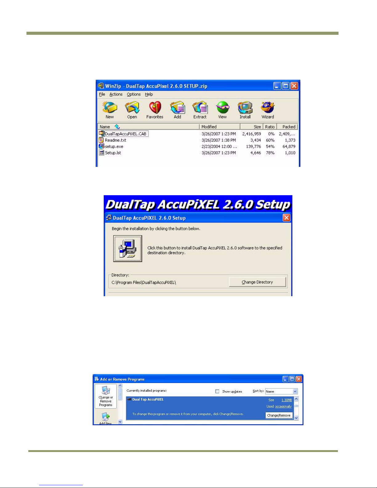
The Setup icon installs Dual Tap AccuPIXel v 2.6.x.x ............................................ 2
List of Figures vii
Page 8

TM/TMC/RM/RMC-2030CL
Figure 51. Field Video Timing--Continuous Mode ............................................................. 34
Figure 52. Change memory settings. ............................................................................ 38
Figure 53. Physical Dimensions .................................................................................. 41
Figure 54. Monochrome Response ............................................................................... 42
Figure 55. Color Response ........................................................................................ 42
viii List of Figures
Page 9

TM/TMC/RM/RMC-2030CL
List of Tables
Table 1 12-Pin Connector ...................................................................................... 18
Table 2 Connector and Pin-out Configurations ............................................................. 19
Table 3 12-Pin Interface Pin-Outs ............................................................................ 21
Table 4 Scan Area Start Points ............................................................................... 24
Table 5 Asynchronous Mode Chart ........................................................................... 32
Table 6 TM/TMC-2030 Command List ........................................................................ 35
Table 7 Command Responses ................................................................................. 36
Table 8 TM-2030CL Camera Specifications Table .......................................................... 40
List of Tables ix
Page 10

TM/TMC/RM/RMC-2030CL
x List of Tables
Page 11

TM/TMC/RM/RMC-2
030C
L
Dual-Tap TM-2030CL Operation Manual
1 Introduction
The Dual-Tap AccuPiXEL software offered for the TM-2030CL is camera control software. It is not used in image
capture, but rather to configure camera functionality. The Cam2Net software and Dual-Tap AccuPiXEL software
have the same capabilities. The Dual-Tap AccuPiXEL software is not needed to use the camera.
If you find it more comfortable to use, or the AccuPiXEL software seems more compatible with your system,
then it may be used instead of Cam2Net to configure camera functionality. The Cam2Net and AccuPiXEL
software can not run simultaneously.
The Dual-Tap AccuPiXEL series cameras are high-resolution, progressive scan cameras with JAI Inc.- proprietary
LUT control and other excellent features. The software for these cameras was developed to function as
standard software for the entire Dual-Tap AccuPiXEL series, and can open either the RS-232 serial port (COM)
or Camera Link. Camera Link users must physically install the Camera Link frame grabber board into the PC.
They must also install the Camera Link API (clserXXX.dll) software. These cameras are specially designed to
capture images in progressive scan (non-interlace) format, producing a full frame of electronic shutter images,
as well as normal images.
Although this software works with all AccuPiXEL cameras, the interface for the TM-2030CL series appears
different from other cameras compatible with this same software, and has various capabilities, depending on
the camera model the software is accessing. The TM-2030CL series software is therefore, specifically
documented in this section
1.1 Software Installation
Following are the instructions to install the Dual-Tap AccuPiXEL series camera-control software on a PC.
1.1.1 Before Installing Dual-Tap AccuPiXEL Series Camera-Control Software
Please note the following requirements.
• Your computer must be running Microsoft Windows 2000, or Windows XP.
• The software requires one available communication port that is not in conflict with other peripherals such
as the mouse or modem.
• Installation of the software requires 2.4 MB of free space in your PC hard disk.
1.1.2 Installing the Software
To install the Dual-Tap AccuPiXEL series camera-control software, obtain the software from the JAI web site
and run “Setup.exe.” The installer will direct you to install the application code.
If dual tap software is already installed on your computer, uninstall the software using the steps in the
Uninstall section.
1. To obtain the Dual-Tap software visit the JAI Inc. web site at http://www.jai.com
2. Click the Support link
3. Click the Software Downloads link under the Customer Support menu
4. Select the camera model number by clicking in the option button.
5. Select either “Open” or “Save” on the install dialog box
Note: The file is compressed, and uses the decompression program installed on your computer. WinZip is used
in this example.Windows XP has an unzip capability as part of the operating system.
Introduction 1
Page 12
TM/TMC/RM/RMC-2030CL
6. Open the file.
7. Double click on the JAI Inc. GigE 2.2.0.1 Install icon.
Figure 1. The Setup icon installs Dual Tap AccuPIXel v 2.6.x.x
8. Follow the Setup instructions.
Figure 2. AccuPIXel Setup screen
1.1.3 Uninstalling the Software
To uninstall the Dual-Tap AccuPiXEL series camera-control software from the control panel, follow the steps
below.
1. Open “Add or Remove Programs” in the control panel.
2. Select “Dual Tap AccuPiXEL” from the lists of the installed software.
3. Click the “Change” or “Remove” button.
Figure 3. The “Add or Remove Programs” utility can uninstall older software.
2 Introduction
Page 13

TM/TMC/RM/RMC-2
030C
L
1.2 TM/TMC-2030CL Camera
Figure 4. Back of the TM/TMC-2030CL
The camera must have all cables properly connected and any required adapters installed and configured to
allow the software to perform the operations on the interface.
Introduction 3
Page 14
2 GUI Features
The following is a list of camera functions that PC serial commands can control. The Dual-Tap AccuPiXEL series
Camera Link cameras use differential serial communication through the Camera Link connector on the rear
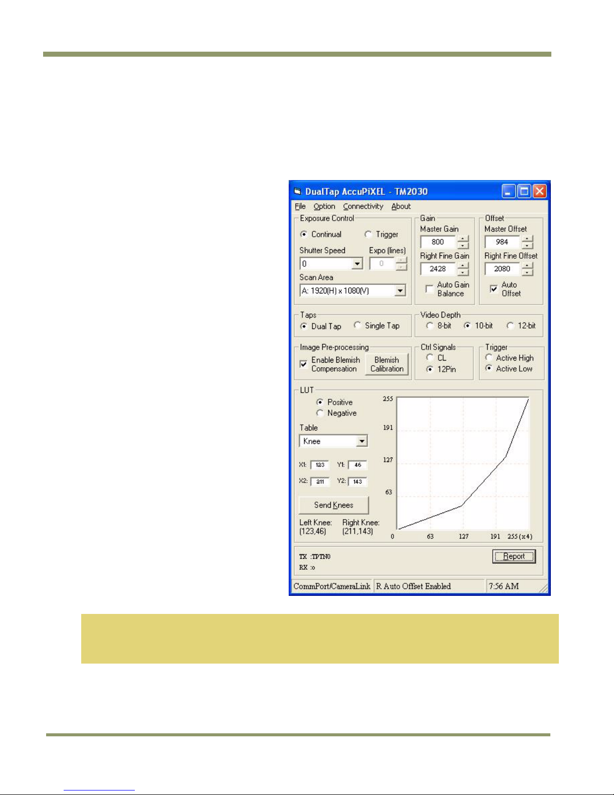
panel of the camera. The interface shown here is for the TM/TMC 2030 CL cameras.
Figure 5. Main Dual Tap AccuPiXEL Window
• Exposure Control
− Continual
− Trigger
− Shutter Speed
− Expo / Lines
− Scan Area
• Gain Settings
− Master Gain
− Right Fine Gain
− Auto Gain Balance check box
• Offset
− Master Offset
− Right Fine Offset
− Auto Offset
• Taps
• Video Depth
• Image Pre-processing
• Control Signals
• Trigger
• LUT
− Positive
− Negative
− Table Selection
− X1, Y1, X2, Y2
− Send Knees
• TX RX Report
TM/TMC/RM/RMC-2030CL
Note: White Balance—Color models of this camera (TMC-2030CL and RMC-2030CL) provide raw Bayer color
output which requires interpolation by means of third party software on the host PC. Similarly, any
white balancing must be performed by hostbased software. There is no white balance control in the
camera hardware or software.
4 GUI Features
Page 15
TM/TMC/RM/RMC-2
030C
L
2.1 Operating The Control Software
2.1.1 Exposure Control
The TM-2030CL exposure control allows you to select Continuous or Trigger modes using the appropriate radio
button. Notice that Continuous and Trigger mode offer slightly different menus.
2.1.1 (a) Continuous Mode Shutter Speed
The Shutter Speed drop-down list box allows you to select the specific shutter speed for manual shutter and
Async shutter. Manual shutter speed 0 is no shutter mode; Async shutter speed 0 is Async No Shutter mode;
Async shutter speed 9 is Async no delay shutter mode (pulse width control). A = PIV fixed exposure, B = PIV
PWC. For detailed shutter information, please see “Electronic Shutter” on page 28.
Figure 6. Continuous mode operates the shutter based on the camera settings.
2.1.1 (b) Continuous mode Scan Area
“Scan Area” offers a full scan or 2x2 binning when “Shutter Speed” is set at zero. Notice the “Expo (lines)”
setting is disabled.
Figure 7. The camera offers full scan or binning.
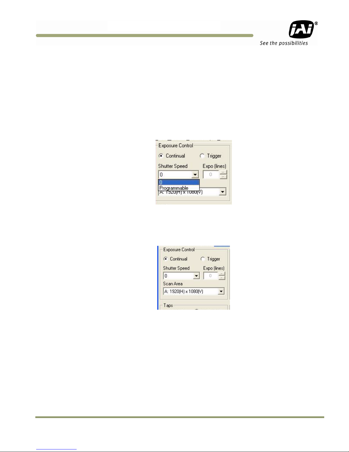
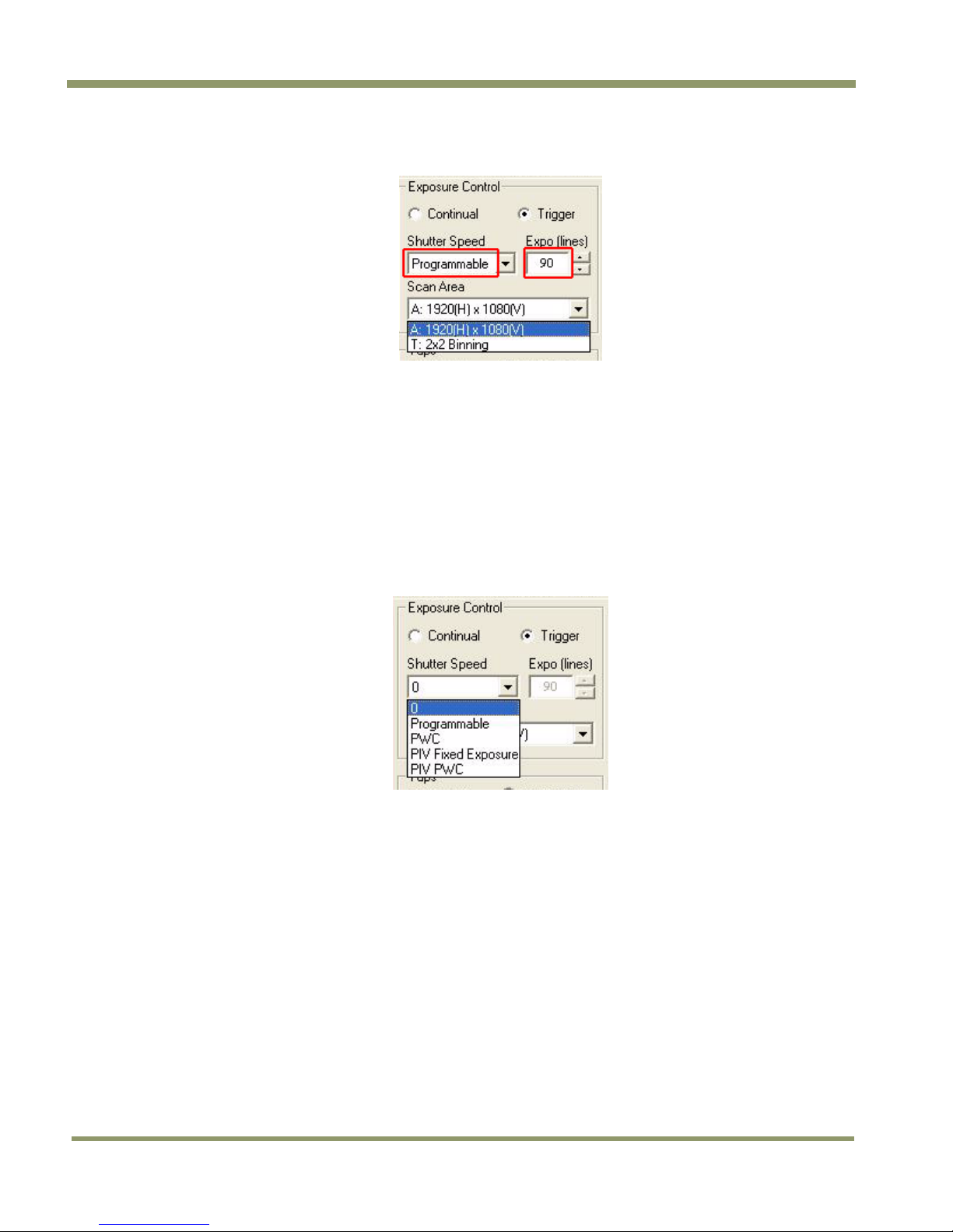
2.1.1 (c) Programmable Shutter Speed
“Programmable” Shutter Speed is set by entering a number in the “Expo (lines)” text box. Programmable is
available in Continuous or Trigger mode. The Expo setting is used instead of the Scan Area selection.
GUI Features 5
Page 16
TM/TMC/RM/RMC-2030CL
Figure 8. To use Programmable shutter speed, select Programmable.
2.1.1 (d) Expo (lines)
The “Expo (lines”) selection of the Exposure Control frame determines how long the shutter remains open,
since a certain amount of time is allotted to expose each line. A minimum of one line of pixels must be
exposed. The maximum number of lines is 2048. Enter the number of lines desired either by clicking on the
arrows in the interface, or by inputting a number directly into the text box beside the “Expo (lines)” box. The
control is inactive unless “Shutter Speed” is set to “Programmable”.
2.1.2 Configuring Trigger Settings
Trigger mode uses a manual or sensor command to control the shutter. The Trigger mode offers several settings
not available in Continuous mode.
Figure 9. Trigger mode shutter settings.
2.1.2 (a) Pulse Width Control Mode
Pulse Width Control (PWC) is controlled by the external trigger. An external trigger is used to generate one
discharge signal (Vsub) right after the active edge of the trigger. The exposure starts when time is controlled
by the pulse width of the external trigger.
2.1.2 (b) PIV Fixed Exposure
In Particle Imaging Velocimetry (PIV) Fixed Exposure Mode, when an external trigger is applied, the first time
exposure starts the same as PWC mode does. It lasts a very short period (8μs). The second time exposure starts
during the transferring time of the first image accumulated in the first exposure time. The second time
exposure continues until the first image transfers completely. The second image is transferred after the second
exposure. There is a short period (500ns) between the first exposure and the second exposure. In order to keep
two exposure periods constant, the LDV is reset before the first image is transferred out.
2.1.2 (c) PIV PWC
The PWC PIV is based on PIV Fixed Exposure. In this mode, the first time exposure is controlled by the pulse
width of the external trigger, which is similar to PWC mode. The real exposure time of the first image is equal
to the pulse width of the external trigger.
6 GUI Features
Page 17

TM/TMC/RM/RMC-2
030C
L
The maximum trigger frequency in this mode is equal to 1/ (transfer time of two frames + exposure time of the
first image).
The minimum active period of the external trigger is 10 pixel clocks (250ns)
2.1.3 Gain Control
2.1.3 (a) Gain
Gain controls the brightness of an image. If the gain number is increased (for example, 1000 to 2000), the
image becomes brighter. If the gain number is decreased, the image becomes dimmer. The Gain Control box
allows you to change the Gain value. Also, if operating the camera in dual-tap mode, the Gain Control allows
you to adjust the balance of the gain between the two channels.
To manually adjust the overall gain, increase or decrease the number in the Master Gain field. In dual-tap
mode, you can manually adjust the balance of channel B (right channel) by altering the number in the Right
Fine Gain field.
To automatically balance the gain between the two channels, check the box labeled Auto Gain Balance. While
the camera is balancing the gain, the user interface is disabled and the label for the check box changes to
“Balancing Please Wait.” Once the right channel gain has been balanced, the check box clears. Be careful not
to send other configuration commands during this process because the camera may not receive the commands.
Figure 10. The Gain is being set when the Auto Gain box appears checked.
Verify that the channel balance process has completed by checking the message area at the bottom of the GUI
window. The message “R Auto Gain Enabled” will appear when completed.
Figure 11. The message bar confirms channel balance status.
During channel balancing, channel B is aligned to channel A. Good channel balance is obtained by exposing the
camera to a uniform light source at under 80% saturation. If the camera is in async trigger mode and the trigger
frequency is low (or slow), it may take longer to collect enough frames to balance the channels. Another
condition in which auto balancing may not work properly is when you use the high-speed shutter under a lowfrequency light, such as a fluorescent light.
2.1.4 Offset Voltage
Offset is changed by raising or lowering the number in the “Master Offset” or “R Fine Offset” box either by
clicking on the arrows or typing a new value in the box.
GUI Features 7
Page 18

TM/TMC/RM/RMC-2030CL
Checking the “Auto Offset” check box causes the camera to automatically adjust the offset. The camera
continues to adjust the offset unless the user unchecks the auto offset; in that case the offset is left off.
When the offset is changed the new setting does not show in the interface. It is necessary to click on the
“Report” button to refresh the screen.
Figure 12. Auto Offset is checked only while the command is being set by the camera.
2.1.5 Tap Selection:
The TM-2030CL is capable of Dual-Tap or Single-Tap operation. Click the option button for the operation you
prefer. Single-Tap operation does not allow the higher data rate permitted by the Dual-Tap output.
Figure 13. Click on the option button to set the preferred option.
2.1.6 Video Depth
Figure 14. Use the option buttons to select 8-bit, 10-bit, or 12-bit output.
Figure 15. Image Pre-processing
Cover the lens with the lens cap before enabling the blemish calibration. Activate this control by clicking the
Blemish Calibration button and then check the “Enable Blemish Compensation” check box. The blemish
compensation activates.
Note: Blemish Calibration is necessary only after a camera has been powered off and restar ted. Once enabled,
blemish compensation remains active unless the user unchec ks the “Enable Blemish Compensation” check
box.
8 GUI Features
Page 19

TM/TMC/RM/RMC-2
030C
L
Figure 16. Image Pre-Processing is activated by checking “Enable Blemish
Compensation”.
2.1.7 LUT (Look-Up Table)
The Knee Control box allows you to set your own knee value to each LUT. See “LUT (Look-Up Table)” on page
28 (section 5.3.1) for more detail regarding the knee control.
2.1.7 (a) Positive or Negative LUT Selection
The LUT control panel allows you to select the positive or negative LUT. Choosing “Positive” provides a normal
image. Choosing the “Negative” option causes the image to appear reversed, as in a film negative.
Figure 17. Choose either a positive or negative image.
2.1.7 (b) LUT (Look-Up Table) Table Selection
The LUT Table drop-down box offers Linear, Gamma .45 or Knee selections.
Figure 18. Table drop down menu:
The Table drop down menu offers three options.
The Linear option gathers light in a proportional manner. In this particular selection the LUT is configured to
speed the light gathering capability at the beginning of the exposure.
The Gamma.45 option is designed to cause the camera to gather light for a result very similar to what the
human eye sees. The heavier curved blue line represents the Gamma.45 LUT adjustment (Figure 19).
GUI Features 9
Page 20

TM/TMC/RM/RMC-2030CL
Figure 19. Gamma.45 imitates human eye sensitivity when creating an image.
The knee setting allows two adjustments in the light gathering configuration of the LUT to permit the camera
to correct images as they are captured. It is possible to set knees on any of the drop down settings by clicking
on the existing curve and moving it to the desired configuration. If a drop-down menu setting is selected
without adjusting the knees, the camera sets the default.
Figure 20. The setting does not activate until the Send Knees button is clicked.
2.1.7 (c) Knee Control
The Knee Control graphical control allows you to change two knee point values visually by clicking and dragging
the “knee line.” You may also enter X1, Y1, X2, Y2 values directly to adjust the knee curve. When you have
chosen the value you want and are ready to set this value to the camera, click the “Send Knees” button.
Note: The use of the Knee LUT may interfere with the Auto Level Control (ALC).
2.1.8 Rx TX Report Frame
This frame of the main GUI window allows you to view the result of actions taken with the Dual-Tap AccuPiXEL
software. Clicking on the “Report” button also sends a command which reads out the current Dual-Tap
AccuPiXEL software settings. This reading can be read using Table 7, “Command Responses,” on page 36.
Figure 21. Click “Report” for current software setting information.
10 GUI Features
Page 21

TM/TMC/RM/RMC-2
030C
L
2.2 Main Menu: “File”
2.2.1 Load and Save Page
Click on the File menu and choose Load Page to load a saved set of camera parameters. The 1 slot contains the
power up default settings.
Figure 22. Load Page
2.2.1 (a) Save Page
Click on the File menu and choose Save Page to change a saved set of camera parameters. The zero slot is used
to store factory default settings, and can not be overwritten without supplying a password.
The 1 slot contains the power up default settings, and can be changed to allow different power up defaults.
The remaining five pages can be used as desired to save configurations.
Figure 23. Save Page
2.2.1 (b) Read Page
Click on the File menu and choose Read Page to read the EEPROM for a specific page. Using this command does
not change the saved configuration.
GUI Features 11
Page 22

2.3 Main Menu Option
Click on the “Option” menu and choose “Password” to gain access to load page 0 of the camera parameters.
Contact JAI Inc. at 1-800-445-5444 for password access. The password allows access to the EEPROM to rewrite
factory default settings.
Figure 24. Password Access
2.3.1 Password
Please contact JAI, Inc. for password access.
Figure 25. Password Screen
TM/TMC/RM/RMC-2030CL
2.3.1 (a) Test Pattern
From the main menu, select “Option” and click ‘Test Pattern” to view or disable the test pattern. This menu
option is disabled if a monitor is not connected to the camera’s video output.
Figure 26. Test Pattern requires a connected camera.
2.3.1 (b) Video Data Output Order
From the main menu, select “Option” and “Video Data Output Order” then choose “<--- <---” or “<--- --->” or
“<<------”
“<--- <---” = First video data are pixel no. 1 and no. 1025.
“<--- --->” = First video data are pixel no. 1 and no. 2848.
“<<------” = First video data are pixel no. 1 and no. 2.
12 GUI Features
Page 23

TM/TMC/RM/RMC-2
030C
L
Figure 27. Video output order
2.3.2 Main Menu “Connectivity”
Click on the “Connectivity” menu to view the buffer size. Some frame grabbers have a small buffer size and
require a special communication algorithm. Use the “Receive Buffer Size” menu to set the buffer size. If you
have trouble communicating with the camera, then select the “Receive buffer is small” option.
Figure 28. Buffer Size
2.3.3 Main Menu “About”
2.3.3 (a) Camera Model
From the main menu, select “About” and click “Camera Model” to check the camera information. The details
display in the information frame near the bottom of the window.
Figure 29. Camera Model
2.3.3 (b) CPU Firmware Version
From the main menu, select “About” and click “CPU Firmware Version” to check the CPU firmware
information.
Figure 30. CPU Firmware Version
GUI Features 13
Page 24

TM/TMC/RM/RMC-2030CL
2.3.3 (c) About Control Software
From the main menu, select “About” and click “About Control Software” to check the software information.
Figure 31. Control Software Version
14 GUI Features
Page 25

TM/TMC/RM/RMC-2
030C
L
3 Hardware Introduction
3.1 Product Description
The JAI Inc. TM/TMC/RM/RMC-2030CL series1 is a high-resolution progressive scan CCD camera. The interlinetype CCD permits full vertical and horizontal resolution of very high speed shutter images and applications. The
electronic shutter, which has speeds to 1/26,000 sec., can be reset asynchronously by external pulse control.
The frame rate for a full image is 32 fps. A square imager format with uniform square pixels provides superior
image definition in any orientation. On-chip micro lenses provide increased sensitivity to convert 12-bit input
to 10-bit or 8-bit output.
2
The TM-2030CL
table (LUT) knee slopes thereby optimizing the CCD’s full dynamic range in the normal output signal range. The
TM-2030CL has semi-auto-gain balancing functions. The camera does not have a LUT for the 12-bit output.
Applications for the TM-2030CL include machine vision, medical imaging, intelligent transportation systems,
high-definition graphics, on-line inspection, gauging, character reading, archiving, and high-security
surveillance.
3.2 Features
• Small size and light weight
The printed circuit boards in the TM-2030CL have been arranged to create modular electronics, giving the
camera flexibility. In addition, the use of miniature solid-state components results in a compact, lightweight
camera that is 51mm x 51mm x 74mm in dimensions, and weighs only 216 grams (7.6 oz.).
has a full dynamic range control function, which can be set at externally selectable look-up
• Imager
The TM-2030CL uses a dual-tap progressive scan interline transfer CCD that has the following features:
− Resolution of 1920 x 1080 active pixels for excellent image quality.
− 7.4 x 7.4 μm square pixels for precise dimensional measurement.
− High-speed electronic shutter capability for high dynamic resolution of moving objects that
eliminates the need for a mechanical shutter.
− Progressive scan CCD eliminates interlace deterioration of image and increases ease of computer
interface.
− High sensitivity and low noise during fast scanning. The CCD has an excellent S/N ratio at the
default setting that is greater than 57dB.
− The CCD for the TM-2030CL has a built-in microlens for increased quantum efficiency.
Note: The Kodak KAI-2093 imager used in the TM-2030CL is packaged using a clear coverglass that does not
have anti-reflective (AR) coatings. This is because the imager is not available from the manufacturer,
Kodak, with AR coating on the coverglass.
The camera will function normally and provide high quality imaging without AR coating. However, in low
light applications that are either high magnification or wide field-of-view, reflections between the back
of the optics and the coverglass may occur. In low light conditions, portions of these reflections may
cause some visible aberrations or ghosting.
• Electronic shutter
The TM-2030CL has a substrate drain-type shutter mechanism which provides superb pictures at various speeds
without smearing. For more information, please see Section 5.5 on page 28.
1
Unless otherwise stated, all information in this manual applies to the TM-2030CL series; the TM-2030CL, TMC-2030CL and
their RoHS compliant RM-2030CL and RMC-2030CL.
2
The TM-2030CL output is available with either 8-bit, 10-bit or 12-bit processing.
Hardware Introduction 15
Page 26

TM/TMC/RM/RMC-2030CL
• Asynchronous reset
The TM-2030CL captures async reset images and provides single-shot video output with single FDV (frame data
valid). This makes it simpler for an ordinary frame grabber to capture the asynchronous reset images. The TM2030CL’s asynchronous reset is flexible and accepts external horizontal drive (HD) for phase locking. When the
VINIT (5V) pulse is applied to CC1, it resets the camera's scanning and purging of the CCD.
The TM-2030CL has three modes to control the asynchronous reset and shutter speed:
− Async, no shutter. The video signal and FDV are reset by external VINIT.
− Internal shutter speed control. The speed control varies from 1/32 to 1/16,000 sec. The video signal
and FDV starts with internal V reset timing related to shutter speed.
− External VINIT with pulse width. The duration between pulse edges controls the shutter speed
externally.
• Output
The TM-2030CL has a dual-tap 12-bit/10-bit/8-bit Camera Link output. The analog output is 1.0 Vp-p composite
video (75 Ω) on all models.
• Dual-channel auto black level balancing and semi-auto gain balancing
The TM-2030CL, as a dual-tap output camera, has auto black level balancing and semi-auto gain balancing
functions.
• Warranty
Please contact your factory representative for details about the warranty.
16 Hardware Introduction
Page 27

TM/TMC/RM/RMC-2
030C
L
4 Installation
The following instructions are provided to help you to set up your camera. We suggest that you read through
these instructions before you unpack and set up the camera system.
4.1 Getting Started
4.1.1 Unpacking Instructions
We recommend that you save the original packing cartons for the cameras and accessories in case you need to
return or exchange an item.
We also recommend that you bench-test any equipment being sent to another location for field installation to
assure that everything is fully operational as a system.
4.1.2 Components
When you receive your TM-2030CL camera from JAI Inc., the contents of the shipping box should include the
camera and a document download card. If either of these items are missing, please contact your JAI Inc.
representative immediately. The document download card includes instructions and web locations for
downloading the datasheet, manual, and camera-control software. If you do not have Internet access, please
contact JAI Inc. to receive this material on a CD-ROM.
4.1.3 Accessories and Options
Following is a list of additional accessories and options that may be required for your application. Please check
with your JAI Inc. representative before you install your camera to determine what you might need.
• PD-12U series power supply
• 12P-02S power cable
• CamLink cable 26-CL-02-26 (2m), or 26-CL-05-26 (5m)
• Tripod Mounting Kit: TP-20
(for dimensions go to: www.jai.com/EN/CameraSolutions/Products/Accessories/Pages/Home.aspx)
4.2 Camera Setup
4.2.1 Heat Dissipation
The TM-2030CL is a compact 1920 by 1080 camera. Since all the electronics have been packed in a compact
package, the outer case of the camera can become hot due to heat dissipation. For optimal performance, JAI
Inc. recommends using a cooling fan to set up a positive air flow around the camera and following the
precautions below.
• Mount the camera on a large heat sink (camera bracket) made out of heat-conductive material like
aluminum.
• Make sure the flow of heat from the camera case to the bracket is not blocked by a non-conductive
material like plastic.
• Make sure the camera has enough open space around it to facilitate the free flow of air.
Please contact JAI Inc. at (800) 445-5444 or send an E-mail to imaging@jai.com if you have any questions.
Installation 17
Page 28

TM/TMC/RM/RMC-2030CL
4.2.2 Connector Pin Configurations
4.2.2 (a) 12-Pin Connector
The TM-2030CL has a 12-pin Hirose connector for power input as shown in Figure 32.
Figure 32. 12-Pin Connector Pinouts
Pin #1 is Ground and pin #2 is +12V DC. Table 7 shows the pin-out table.
Table 1 12-Pin Connector
Pin Description
1 GND 7
2 +12V DC 8
3 GND 9
4 Analog Video 10
5 GND (digital) 11
6 VINIT in 12
4.2.2 (b) Digital I/O Connector
The TM-2030CL has a 26-pin connector on the rear panel to output Camera Link data. The connector pin-out is
shown in Table 2 on page 19
Pin
Description
VD in
Strobe out
HD in
Reserved
Reserved
Reserved
Figure 33. 26-pin Camera Link Connector.
18 Installation
Page 29

TM/TMC/RM/RMC-2
030C
14
15
16
17
18
19
20
21
22
23
24
25
26
L
Table 2 Connector and Pin-out Configurations
Camera Link Connector
Pin # Description I/O
1 GND
2 Tx OUT 0- Out
3 Tx OUT 1- Out
4 Tx OUT 2- Out
5 Tx CLK OUT - Out
6 Tx OUT 3- Out
7 SerTC+ In
8 SerTFG- Out
9 VINIT In
10 Reserved In
11 EX-HD- In
12 EX-VD+ In
13 GND
Note: SerTC: Serial To Camera
SerTFG: Serial to Frame Grabber
4.2.2 (c) Analog Output Connector
The TM-2030CL has a BNC connector on the rear panel to output the analog video signal. Analog output is
available to drive auto-iris lenses and troubleshooting.
Note: This analog signal is not an RS-170 (television format) signal that can be connected to a standard CCTV
monitor.
Pin #
Description
GND
Tx OUT 0+
Tx OUT 1+
Tx OUT 2+
Tx CLK OUT+
Tx OUT 3+
SerTC-
SerTFG+
VINIT+
Reserved
EX-HD+
EX-VD-
GND
I/O
Out
Out
Out
Out
Out
In
Out
In
In
In
In
Figure 34. BNC Connector.
4.2.3 Camera Link Cable
The 26CL-02-26 cable assembly has been standardized as the Camera Link cable. This cable has a 26-pin
connector on both ends. This is a straight-through cable and the pin-out configuration is shown in Table 2 on
page 19. Contact JAI for cable lengths other than 2 meters.
Installation 19
Page 30

TM/TMC/RM/RMC-2030CL
Figure 35. 3M Camera Link Cable
Note: For CL versions, serial communication for camera control is accomplished by means of the Camera Link
connector on the rear panel of the camera.
4.2.4 Power Supplies and Power Cable Setup
4.2.4 (a) Power Supplies
The TM-2030CL camera requires 12V DC power that is obtained through the 12-pin connector located on the
back panel of the camera. JAI Inc. power supplies feature a 100-240V AC/12V DC 1.2A universal voltage power
supply. JAI Inc. recommends the following power supplies:
PD-12UU No 12-pin connector
PD-12UUP PD-12UU with 12-pin connector
PD-12UE PD-12UU no 12-pin connector
PD-12UEP PD-12UU with 12-pin connector
For users providing power through the 12-pin connector, the PD-12P, PD-12UEP and PD-12UUP power supplies
are available with the 12-pin mating connector already attached to the leads from the power supply. The PD12UU and PD-12UE power supplies can be connected to the JAI Inc. power cable either directly or using a
terminal strip.
When wiring the PD-12UU and PD-12UE power supplies directly, please note the following:
• The lead ends must be twisted together and tin-soldered for strength and electrical continuity.
• Shrink tubing or a similar insulator should be used to prevent exposed leads from touching and shorting.
• The +12V lead is marked with a red stripe or white lettering; be sure not to reverse the leads.
• All connections must be properly insulated to prevent shorting.
4.2.4 (b) JAI Inc. Power Cables
If you are using JAI Inc. power cables such as the 12P-02S, please refer to the 12-pin connector pinout diagram
below. The cable pin-out diagram is shown in Figure 36. The color-coded leads use Gray for Ground and Yellow
for +12V.
US Plug
US plug
European plug
European plug
20 Installation
Page 31

TM/TMC/RM/RMC-2
030C
7
8
9
L
Figure 36. 12P-02S Interface Cable (optional)
Table 3 12-Pin Interface Pin-Outs
12P-02S Interface Cable
Pin# Lead Color Function
1 Gray GND
2 Yellow +12V DC
3 Red coax shield GND(analog)
4 Red coax RESV
5 Orange coax shield GND(Digital)
6 Orange coax TTL IN (EXT_TRIG) 12
Note: Make sure that the unused leads are not touching and that there is no possibility that exposed wires
could cause the leads to short.
4.2.4 (c) Building Your Own Power Cable
Refer to the 12-pin connector pin-out in Figure 32 on page 18. Connect the Ground lead to pin #1, and the +12V
DC lead to pin #2 of the 12-pin connector. Power must be DC-regulated, and of sufficient current to properly
power the camera.
4.2.4 (d) Attaching the Power Cable to the Connector
The 12-pin connector is keyed and will only fit in one orientation. Follow these directions to properly attach
the power cable to the camera connector:
1. Rotate the connector while applying slight pressure until the keyways line up.
2. Press the connector into place until firmly seated.
3. Plug the power cord into the 100V AC socket. This powers-up the camera.
Pin#
10
11
Lead Color Function
Black coax
White coax shield TTL OUT (STROBE)
White coax
Brown
Blue
Black coax shield Reserved
TTL IN (EXT_VD)
TTL IN (EXT_HD)
Reserved
Reserved
4.2.5 Attaching the Camera Lens
The TM-2030CL camera accepts 1-inch or larger format size C-mount lenses. To attach the C-mount lens3 to the
camera, carefully engage the threads and rotate the lens clockwise until it firmly seats on the mounting ring.
Do not force the lens if it does not seat properly. Some lenses with extremely long flange backs may exceed the
mounting depth of the camera.
4.2.6 Adjustable Back-Focus
Before cameras are shipped, back focus is carefully set using a collimator, oscilloscope and other specialized
equipment. While the factory-set focus serves well in most cases, an adjustable back focus makes it possible to
improve image sharpness when using lower-cost zoom lenses, custom optics, or in unusual parameters.
3
C-mount to F-mount and C-mount to K-mount adapters are available for larger format lenses (35mm). Check with local
photography dealers for these lens adapters.
Installation 21
Page 32

TM/TMC/RM/RMC-2030CL
There should be an obvious need to refocus the lens before attempting to change the back focus. This is a very
exacting task. Some cameras have been returned to the factory to reset the back focus after failed attempts to
change the focus by customers. It might be wise to label cameras whose back focus was adjusted.
1. The camera must be connected to a monitor before attempting to adjust the back focus.
2. To back focus the camera, first attach a C-mount lens in the mount. Be certain that the lens is properly
seated.
3. Next set the lens focus to infinity (if the lens is a manual iris, set the iris to a high f number while still
retaining a well illuminated image).
4. Loosen the three miniature hex set-screws (use a 0.9 mm hex wrench) that lock the focus ring in place (two
screws for a CS-mount). Slowly turn the lens and focus ring assembly back and forth until you obtain the best
image of the desired object. This sets the back focus. Once the best image is obtained, tighten the focus ring
set-screws until they are snug. Do not over-tighten the screws.
Note: Mini-bayonet cameras adapted to C-mount do not have the back focus feature.
Figure 37. Back Focus Set-Screw Locations
22 Installation
Page 33

TM/TMC/RM/RMC-2
030C
L
5 Operation
5.1 Progressive Scanning
Standard TV-system scanning is 525 lines interlace scanning as specified in the RS-170 protocol. Every other
horizontal line (odd lines and even lines) is scanned at a 60Hz rate per field, and the scanning is completed
with two fields (one frame) at 30Hz rate. Because of the interlace scanning, the vertical resolution of CCD
cameras is limited at 350 TV lines, regardless of the horizontal resolution. When electronic shutter is applied,
the CCD can hold only one field of charge at each exposure. This means that the vertical resolution of the
electronic-shutter camera is only 244 TV lines. The situation is the same for an HDTV-format camera, since it
has interlaced scanning and the vertical resolution of the shuttered image is 500 lines.
The TM-2030CL uses a state-of-the-art progressive scanning interline transfer CCD which scans all lines
sequentially from top to bottom at one frame rate. Like a non-interlace computer screen, it generates a stable,
crisp image without alternating lines and provides full vertical TV resolution of 1000 lines (a normal TV monitor
display may not be able to show 1000 lines due to monitor resolution of 30Hz scanning).
The interline transfer architecture is also important to generate simultaneous shuttering. This is different from
full frame transfer architecture which requires a mechanical shutter or strobe light in order to freeze the
object motion.
5.1.1 Preset Scan Area
TM/TMC-2030CL has full scan mode, all active lines of the CCD sensor, 1080 lines, are transferred out line by
line.
5.1.2 Full Scan Area 2x2 Binning
TM/TMC-2030CL has a 2x2 binning of the full scan area. In 2x2 binning mode, pixel (i, j) includes all the
information of pixel (2i-1, 2j-1), (2i-1, 2j), (2i, 2j-1) and (2i, 2j) in normal full scan mode (where i=1 2, ..., 800;
j=1,2, ...., 540). In this mode vertical binning makes frame transfer faster than normal scan mode, however,
due to the mixture of pixel information, the camera resolution is low in this mode, and the Bayer pattern CCD
camera loses color information.
Operation 23
Page 34

TM/TMC/RM/RMC-2030CL
Figure 38. 2x2 Binning
Table 4 Scan Area Start Points
Scan Area
A Full Scan 1
1 Full Scan 2x2 Binning 1
Start Point
(Line)
Effective Area
(Lines x Pixels)
1920 x 1080
960 x 540
Frame Rate (FPS)
Dual Tap Single Tap
32.32 16.16
58.65 30.79
5.2 Bayer Color Filter (Color Versions)
JAI Inc. AccuPiXEL series color cameras are high-resolution, high-speed progressive scan CCD cameras. The
interline transfer, progressive scan CCD permits full vertical and horizontal resolution of images acquired at
very high shutter speeds. The electronic shutter, which has speeds up to 1/26,000 sec., can be reset
asynchronously by external pulse control. Uniform square pixels provide superior image definition in any
orientation. On-chip micro lenses mean increased sensitivity.
5.2.1 Color Filter Array
JAI Inc. AccuPiXEL cameras use Bayer CFA (color filter array) as their standard primary color filter. This filter
provides the most popular color interpolation supported by numerous software suppliers.
The digital format allows the camera to output accurate pixel data, including the color information. When the
data is stored in the frame buffer of a frame grabber or computer, the color information is easily manipulated
to restore the original color images. Because the color filter array contains only a single R, G or B color in each
pixel, the restored image has to fill in colors in the missing pixel locations. The software uses neighboring pixel
information to “guess” the missing colors to make smooth, clear images. This is called “color interpolation.”
Today’s high-speed computers allow such color interpolation to be done almost in real time. Because these
cameras do not contain internal color processing circuitry, they are smaller and less expensive than fullfunction color cameras.
5.2.2 Bayer Color Filter Array (CFA)
The Bayer CFA is an R, G, B primary color filter array. This is the most widely accepted CFA for the single-chip
CCD progressive scan format. This type of array layout has a specific order for each color’s pixels. Since the
human eye’s resolution and color recognition are highest at green, the CFA contains two greens per each red
and blue.
24 Operation
Page 35

TM/TMC/RM/RMC-2
030C
L
It is critical for the frame grabber and color interpolation to know where the individual color pixels exist
relative to sync (LDV and FDV) timing.
This requirement makes digital output the preferred choice, because the timing relationships are very accurate
Figure 39. Bayer Color Filter Response.
5.2.3 Starting Pixel Configuration
All manufacturers produce identical Bayer CFAs, but there are slight differences between the CCDs produced by
different manufacturers. The first line is generally R and G. The camera timing can be adjusted to start with
either G or R by skipping the very first pixels at each line. The majority of color interpolation software can
select between a variety of pixel relations, such as R/G start or G/R start, as well as G/B start and B/G start.
Once the correct scanning is configured, the rest of the interpolation is exactly the same. Contact JAI Inc. for
further information regarding CCD manufacturers.
Figure 40. Example of Color CCD CFA Pattern
Operation 25
Page 36

TM/TMC/RM/RMC-2030CL
5.2.4 Sync and Data
The individual color data is exactly the same as the pixel data. This means that the timing relationships of the
color cameras are also the same as of the monochrome cameras.
For a detailed timing chart, please refer to each monochrome camera’s data sheet and manual.
The following diagram is an example of the TMC-2030CL default mode. FDV and LDV are used internally for the
GigE interface.
Figure 41. Example of TMC-2030CL (Same as TM-2030CL)
5.2.5 Camera Functions
AccuPiXEL color cameras perform all functions the same way as monochrome cameras. However, because of
color characteristics, the LUT (Look-up Table) is different. The LUT is a powerful tool to adjust the dynamic
range as well as color dynamic range. Since human color perception is non-linear, LUT selection can help
optimize color contrast by selecting the LUT value. Gamma 0.45 is logarithmic and is closed to human
perception.
When LUT is selected, black-level adjustment must be more accurate than for monochrome cameras.
5.2.6 Interpolation Software
The color interpolation can be performed in the frame grabber or by using the host computer’s CPU. Most
major frame grabbers with processing capability provide tools for color interpolation. Software vision packages
also provide color interpolation capability, but speed and performance may be determined by the PC’s
resources and by the complexity of the interpolation routine.
26 Operation
Page 37

TM/TMC/RM/RMC-2
030C
L
5.2.7 Color Interpolation
The Bayer pattern color filter array (CFA) consists of R, G, and B primary colors. Each pixel represents one of
three colors. In order to display or print color images, the signal has to be converted to RGB output, which has
three independent channels (outputs) and sync signals.
Color interpolation software or firmware performs the color preprocessing by filling the missing color pixels
with neighboring pixels. It then separates the stream of data, (8-bit or 10-bit) into 3 (RGB) data (8-bit x 3) and
adds the color matrix to adjust and balance each of the R,G, and B channels (white balance or color balance).
Figure 42. Color Interpolation Diagram
The image quality depends on the camera’s own pixel data (including pixel data independency from
neighboring pixels, noise and color filter), and interpolation of the software algorithm such as 3 x 3
interpolation, 2 x 2 interpolation, color matrix, white balance capability, and so on.
All AccuPiXEL color cameras are carefully designed for maximum color performance. JAI Inc. strongly suggests
that you use digital output for the best performance.
Some software is used on board (FPGA or DSP) to perform the interpolation. Other software simply uses the
host computer’s memory and CPU. The process speed may vary depending on the architecture and speed of the
computer.
5.3 Dynamic Range Control
Figure 43. Output and Blooming
The typical interline transfer CCD has fixed noise levels based on dark current (thermal or KT noise), pattern
Operation 27
Page 38

TM/TMC/RM/RMC-2030CL
noise, and the operating clock speed. In general, the level of the 20 MHz pixel clock CCD at room temperature
is around 20 to 50 electrons. The maximum capacity of CCD charges is limited by the well capacity at
saturation. The range is limited by the structure and the pixel size.
The TM-2030CL uses a CCD with 7.4 ?m x 7.4 ?m pixel and two-phase vertical shift register structure. The well
capacity is 40,000 electrons. The theoretical dynamic range is 40,000:30 = 1333:1 (60 dB).
A typical CCD camera does not use the full dynamic range due to the nominal gain and the output specification
such as RS-170. The typical CCD camera’s gain is set at 16 to 22 dB and the RS-170 video level is 714 mV. Using
20 dB gain for the calculation, CCD output is limited to 714/10 = 71.4 mV. Since the CCD’s saturation voltage is
400 mV to 500 mV, it uses less than 1/5 of the full dynamic range.
Machine vision and outdoor applications, cannot afford to miss image information behind the saturation, which
is why the dynamic range adaptation is critical.
5.3.1 Programmable Look-Up Table (LUT) and Knee Control
The TM-2030CL has a built-in LUT (look-up table) for dynamic range control.
At a specific gain setting, the offset (minimum level.... dark point) and A/D reference top voltage (maximum
level... saturation point) are set to 12-bit A/D input so that the full dynamic range of the CCD is utilized at 12bit references as the input and the LUT output is converted into either 8-bit or 10-bit to adjust the gamma
correction. There is no 12-bit LUT.
The look-up table has two knee points (variable gamma selection) that allow the 10-bit input to be segmented
into three regions. The look-up table selection can be made by knee curve direct input.
5.4 External Sync and Pixel Locking
The TM-2030CL accepts an external sync of standard HD and VD at TTL level for general locking to a system
sync and clock. The frequency requirement is as follows:
Full Progressive Scan:
fHD = 36.36 KHz ± 2%
fVD = 32.32 Hz ± 2%
(Internal Master clock = 80.00 MHz,
Pixel clock = 40.00 MHz)
5.5 Electronic Shutter
The TM-2030CL has a substrate drain-type shutter mechanism which provides a superb picture at various speeds
without smearing.
5.5.1 Programmable Exposure-Continuous Mode
The exposure time of TM/TMC-2030CL can be specified from one video line to a maximum of one frame using
the serial communication commands in the Continuous Mode. There is overhead where the specified exposure
time is n video lines, making the real exposure time equal to
When n=0, the exposure time is the minimum exposure time. It is equal to:
In this mode the maximum exposure time is equal to the setting for one frame. If the user specified exposure
time is longer than the time allowed for one frame, it will be ignored by the camera.
5.5.2 Asynchronous No Shutter Mode
In Asynchronous No Shutter Mode, applying the external trigger starts a camera scan reset. The camera finishes
the line it is scanning and scans an additional 9 video lines, this charge is sent to the horizontal register.
28 Operation
Page 39

TM/TMC/RM/RMC-2
030C
L
Because the external trigger is randomly applied, the new image charge may overlap with the previous image.
To prevent an existing charge accumulation from interfering with a new image, most users set up the
application in a dark area and depend on a strobe light for illumination. From the time the external trigger
activates until the transfer gate turns off, about 9.5 video lines are available for integration; if everything is
properly configured, the strobe flashes during this time.
Figure 44. External Trigger Timing.
5.5.3 Asynchronous Programmable Exposure Mode
In Asynchronous Programmable Exposure Mode, when an external trigger is applied, the exposure starts after
one discharge signal (Vsub), which happens after the trigger’s active edge is off. Because the discharge signal
(Vsub) synchronizes with LDV in this mode, there is a maximum one video line of jitter between the trigger
active edges to discharge signals (Vsub) off. In this mode, the exposure time from 1 video line to 2080 video
lines can be controlled through serial communication commands in one video line steps. In this mode, the
minimum exposure time is equal to 1 video line plus overhead: the maximum exposure time is equal to 2080
video lines plus overhead. Where the specified exposure time is n video lines, the real exposure time is equal
to:
When n=0, the exposure time is minimum exposure time. It is equal to:
When n=1124 the exposure time is maximum exposure time. It is equal to:
Operation 29
Page 40

TM/TMC/RM/RMC-2030CL
• If the exposure time is less than one frame time, the maximum trigger frequency is equal to 1/1
frame time.
• If the exposure time is longer than one frame time, the maximum trigger frequency is equal to
1/exposure time.
• The minimum active period of the external trigger is 5μs.
Figure 45. Asynchronous Programmable External Trigger
5.5.4 Pulse Width Control Mode
In Pulse Width Control (PWC) Mode, the exposure time is controlled by the external trigger. When an external
trigger is applied, one discharge signal (Vsub) is generated right after the active edge of the trigger. The
exposure starts when the discharge signal is in the off state. The exposure is off following the trigger active
off. Exposure time is controlled by the pulse width of the external trigger. Because the CCD requires some
overhead from trigger active off to the transfer gate event, the actual exposure time is equal to:
Exposure Time = Pulse Width +12.4μs
Since one discharge signal (Vsub) is generated right after the active edge of the trigger, it is asynchronous with
LDV, and the discharge signal may happen during an active video transfer period, visible reset noise may show
in the current image. To avoid reset noise, the maximum trigger frequency in PWC mode should be less than 1/
(exposure time + one frame transferring time).
The minimum active period of the external trigger is 5?s. Theoretically, the maximum active period of the
external trigger is unlimited. But, due to the usability of images at 25oC it is recommended the active period of
the external trigger be no longer than one second.
30 Operation
Page 41

TM/TMC/RM/RMC-2
030C
L
Figure 46. Pulse Width Control Trigger
5.5.5 Particle Imaging Velocimetry Fixed Exposure Mode
In Particle Imaging Velocimetry (PIV) Fixed Exposure Mode, when an external trigger is applied, the first time
exposure starts the same as PWC mode does. It lasts a very short period (8μs). The second time exposure starts
during the transferring time of the first image accumulated in the first exposure time. The second time
exposure continues until the first image transfers completely. The second image is transferred after the second
exposure. There is a short period (500ns) between the first exposure and the second exposure. In order to keep
two exposure periods constant, the LDV is reset before the first image is transferred out.
The maximum trigger frequency in this mode is equal to 1/ (transfer time of two frames + 4μs). The minimum
active period of the external trigger is 5μs
Figure 47. PIV Exposure Timing Table
Operation 31
Page 42

TM/TMC/RM/RMC-2030CL
5.5.6 PWC PIV Mode
The PWC PIV is based on PIV Fixed Exposure. In this mode, the first time exposure is controlled by the pulse
width of the external trigger, which is similar to PWC mode. The real exposure time of the first image is equal
to the pulse width of the external trigger.
The maximum trigger frequency in this mode is equal to 1/ (transfer time of two frames + exposure time of the
first image).
The minimum active period of the external trigger is 10 pixel clocks (250ns)
Figure 48. PWC PIV Timing Table.
Table 5 Asynchronous Mode Chart
Asyn No Shutter Async Preset and Prog. Shutter
aA <1 line <1 line
aB 9.5 line (n+1) lines + 298 clk
aC
PIV Fixe Expo PIV PWC
pA 6 6
pB 70 70
pC 200 200
pD 320 320
pE 20 20
pF 1 1
PWC
6 clk
Pulse width + 48 clk
48 clk
Unit
Pixel
Frame
32 Operation
Page 43

TM/TMC/RM/RMC-2
030C
L
5.6 Camera Timing Charts
Figure 49. Camera Timing Chart
Figure 50. Digital Data Output Order for Configuration
Operation 33
Page 44

TM/TMC/RM/RMC-2030CL
Figure 51. Field Video Timing--Continuous Mode
34 Operation
Page 45

TM/TMC/RM/RMC-2
030C
R
L
6 Camera Serial Commands
You can control the C series cameras by serial command either using RS-232 or Camera Link. The Start
character is always “:” and the End character is always <CR> (return). For example, to set Asynchronous Pulse
Width Mode, send the command :ASH=9<CR> to the camera. Table 6 lists serial commands that can be used to
control the camera.
Table 6 TM/TMC-2030 Command List
Command Parameter End of Cmd Ack. Response
Scan Mode
Shutter Mode and Shutter Speed
:MSH= X <cr> :o<cr>
:DSH= XXX <cr> :o<cr>
:ASH= X <cr> :o<cr>
:ADS= XXX <cr> :o<cr>
:SHR? <cr> :o[shtr]<cr>
Gain and Offset
:MGA= XXX <cr> :o<cr>
:MGB= XXX <cr> :o<cr>
:VRA= XXX <cr> :o<cr>
:VRB= XXX <cr> :o<cr>
:MGA? <cr> :oMG[XXX]<cr> Inquire Master Gain (XXX = 000 - FFF)
:MGB? <cr> :oSG[XXX]<cr> Inquire R channel Fine Gain (XXX = 000 - FFF)
:VRA? <cr> :oMF[XXX]<cr> Inquire Master Offset (XXX = 000 - FFF)
:VRB? <cr> :oSF[XXX]<cr> Inquire R channel Fine Offset (XXX = 000 - FFF)
Lookup Table
:LINR <cr> :o<cr>
:GM45 <cr> :o<cr>
:KNEE= X1Y1X2Y2 <cr> :o<cr>
:NLUT X <cr> :o<cr>
:LUT? <cr> :o[lut]<cr>
Channel Balance
:EABL <cr> :oAB0<cr>
:DABL <cr> :o<cr>
:ABL? <cr> :oAB[X]<cr>
:ACL= X <cr> :o[AC][X]<cr>
EEPROM
:WRPG X <cr> :o<cr>
:LDPG X <cr> :o<cr>
:RDPG X <cr> :o[settings]<cr> Read Page (X = 0 - 6)
:RPST <cr> :o[settings]<cr> Report Current Settings
Set Continuous Mode Preset Shutter ( X= 0)
Set Continuous Mode Programmable Shutter
( XXX=000 - total lines)
Set Async Mode Preset Shutter (X=0, 9, A, B)
( X=0 async no shutter) ( X=9 PWC, X=A Fixed
exposure PIV, X=B PWC PIV)
Set Async Mode Programmable Shutter
(XXX=000 - 81F)
Inquire current shutter mode
Set Master Gain (XXX = 000 - FFF)
Set
channel Fine Gain (XXX = 000 - FFF)
Set Master Offset (XXX = 000 - FFF)
Set R channel Fine Offset (XXX = 000 - FFF)
Set linear table
Set gamma .45 table
Set knees (X1, Y1, X2, Y2 = 00 - FF)
Set Positive Knee or Negative Knee
(X = 0 Positive, X = 1 Negative)
Inquire current LUT setting
Enable Gain Balancing
Disable Gain Balancing
Check Gain Balancing Status (X = 1 Enable,
X = 0 Disable)
Enable/Disable Optical Black Balancing and
Inquire Status (X = 0 Disable, X = 1 Enable,
X = ? Inquire Status)
Write Page (X = 0 - 6) (Unlock the Password first
if writing to page 0) (Page 0 is the factory
default setting, Page 1 is the power up default
setting)
Load Page (X = 0 - 6)
Description
Camera Serial Commands 35
Page 46

TM/TMC/RM/RMC-2030CL
Command Parameter End of Cmd Ack. Response
Dual Tap Digital Video Output Order
:VDO X <cr> :o[VD][X]<cr>
Image Pre-processing
:BLC= 0 <cr> :o<cr>
:EBL= X <cr> :o[BL][X]<cr>
Miscellaneous
:DUL= X <cr> :o<cr>
:DDP= X <cr> :o<cr>
:CCS= X <cr> :o<cr>
:TAH= X <cr> :o<cr>
:TPTN X <cr> :o<cr>
:CAM? <cr> :o[model]<cr> Inquire Camera Model
:VER? <cr> :o[version]<cr> Inquire MPU firmware version
Set Dual Tap Digital Video Output Order (X = A,
B, C, ?) (A <--<--, B <---->, C <<----, ? Inquire
video output order)
Set White Blemish Calibration Flag
Enable/Disable Blemish Compensation and
Inquire Status (X = 0 Disable, X = 1 Enable,
X = ? Inquire Status)
Single Tap/Dual Tap Selection (X = 0 Dual Tap,
X = 1 Single Tap)
Set Output Data Depth (X = 0 8-bit, X = 1 10-bit,
x = 2 12-bit)
Select Camera Control signals (X = 0 CL Conn,
X = 1 Hirose Conn)
External Trigger Polarity (X = 1 Active High,
X = 0 Active Low)
Enable/Disable Test Pattern (X = 1 Enable,
X = 0 Disable)
Description
Note: If a command is not accepted for any reason, the camera will return a “nack” response. “:e” <cr> *Not
available yet.
Table 7 Command Responses
Command Parameter End of Cmd
Byte 1, 2
Byte 3, 4
Byte 5, 6
Byte 7, 8
Byte 9 Function Flag 0
Bit 1
Bit 3
Bit 5
Byte 10
Bit 0
Bit 2
Master Gain
R Channel Fine
Gain
Master Offset
R Channel Fine
Offset
Bit 0
Bit 2
Bit 4
Bit 6
Bit 7
Function Flag 1
Bit 1
Bit 3
Master Gain (H'0000 - H'0FFF: -3dB - +12dB)
Master Offset (H'0000 - H'0FFF)
Rsvd
Rsvd
Rsvd
Rsvd
Rsvd
Rsvd
Pixel Output
Order 0
Pixel Output
Order 1
Shutter 0
Shutter 1
Shutter 2
Shutter 3
R Channel Fine Gain (H'0000 - H'0FFF)
R Channel Fine Offset (H'0000 - H'0FFF)
00=<---<--- 01<=<------>
10=<<------
Continuous Mode: 0000
Continuous no shutter
Trigger mode: 0 = Async no shutter
1001=PWC 1010=PIV Fixed Exposure
1011=PIV PWC
Description
36 Camera Serial Commands
Page 47

TM/TMC/RM/RMC-2
030C
L
Command Parameter End of Cmd
Bit 4
Bit 5
Bit 6 Data Depth 0
Byte 11
Bit 0
Bit 2
Bit 4
Bit 6
Byte 12 Function Flag 3
Bit 3
Bit 5
Byte 13, 14
Byte 15, 16
Byte 17, 18
Byte 19, 20
Byte 21, 22
Byte 23, 24 Vsub Voltage
Bit 7
Function Flag 2
Bit 1
Bit 3
Bit 5
Bit 7
Bit 0
Bit 1
Bit 2
Bit 4
Bit 6
Bit 7
(X1, Y1)
(X2, Y2)
Shutter Speed of
Programmable
Shutter
Shutter Mode 0
Shutter Mode 1
Data Depth 1
Look-up table 1
Rsvd
Camera Control
Signals
Rsvd
Trigger Signal
Polarity
Dual / Signal Tap
Positive /
Negative LUT
R Channel Auto
Fine Gain
R Channel Auto
Fine Offset
Rsvd
Rsvd
Blemish
Compensation
Rsvd
Password
Test Pattern
Rsvd
Rsvd
00=Continuous Preset Shutter
01=Trigger Preset Shutter
10=Trigger Programmable Shutter
11=Continuous Programmable Shutter
00=8bit 01=10bit
10=12bit
00=Linear 01=Gamma.45
10=User Knee Table
0=CameraLink Connector
1=Hirose 12pin Connector
0=Active Low 1=Active High
0=Dual Tap 1=Single Tap
0=Positive LUT 1=Negative LUT
0=Disable 1=Enable
0=Disable 1=Enable
0=Disable 1=Enable
0=Disable 1=Enable
0=Disable 1=Enable
Coordinate for Knee 1 (X1, Y1=H'00 - H'FF)
Coordinate for Knee 2 (X2, Y2=H'00 - H'FF)
Shutter Speed of Programmable Shutter
(H'0000 - H'081F)
Vsub Voltage (H'0600 - H'0D00=7.8V - 17V)
Description
Camera Serial Commands 37
Page 48

7 Troubleshooting
7.1 Problems and Solutions
Following are troubleshooting tips for common problems. In general, the problems listed in this section are
solved by following these instructions. If there is no solution listed to the problem you are encountering,
contact a JAI Inc. representative.
7.1.1 Symptom: No Video
Remedies: Check that the following are properly connected and operational.
• Power supplies
• Power cables
• Main power source
• Shutter control
• Async mode
• Lens
• Digital output cable
• Analog video cable
7.1.2 Symptom: Dark Video
Remedies: Check that the following are properly connected and operational.
TM/TMC/RM/RMC-2030CL
• Shutter selection
• Iris opening on the lens
7.1.3 Symptom: Non-Synchronized Video
Remedies: Check that the following are properly connected and operational.
• Proper mode output
• Frame grabber software camera selection
7.1.4 Symptom: Video does not Display Properly
Remedies: Open the Coyote software and click on the Display heading. If the display is set to Use video memory
change it to Use system memory.
Figure 52. Change memory settings.
7.1.5 Symptom: Notebook Computer Driver Installation Problems
Remedies: The IBM T-42 laptop is unable to properly install.
38 Troubleshooting
Page 49

TM/TMC/RM/RMC-2
030C
L
7.1.6 Information and Support Resources
For further information and support:
North American Technical Support
Phone 408-383-0300
E-Mail: camerasupport@jai.com
European Technical Support
Phone: +45 4457 8916
E-Mail: camerasupport@jai.com
Japan/Asia Technical Support
Phone +81 45 440 0154
E-Mail: tsh@jai.com
Mail:
JAI Inc.
Sales Department
625 River Oaks Parkway
San Jose, CA 95134
ATTN: Video Applications
Web Site: www.jai.com
Troubleshooting 39
Page 50

8 Appendix
8.1 Specifications
Table 8 TM-2030CL Camera Specifications Table
Sensor 1" progressive scan interline transfer CCD
Active Area 14.2mm x 8.0mm
Active Pixels 1920 (H) x 1080 (V)
Cell Size 7.4μm x 7.4μm
Readout Mode
(Active Pixels)
Sync Internal/External auto switch
Data Clock Output 40.00 MHz
Resolution Digital: 1920 (H) x 1080 (V),
S/N Ratio >57dB min.
Min. Illumination Monochrome: 0.45 lux. Color: 3.6 lux.
Video Output Digital output: 8-bit / 10-bit /12-bit Gigabit Ethernet
Gamma Programmable LUT (1.0 std.)
Lens Mount C-mount (use >1" format lenses or larger)
Power Requirement 12V DC, ±10%, 520mA (typical at 25°C)
Operating Temp. -10°C to 50°C*
Vibration 7 Grams (10Hz to 2000Hz) Random
Shock 70G, 11 ms half sine
Size (W x H x L) 51mm x 51mm x 74mm
Weight 188 grams (7.5 oz.) without tripod
Optional Functions OP3-1 Internal IR Filter Added;
Optional Accessories
Power Cable
Power Supply
Tripod Mounting Kit
*. Refer to Section 4.2.1 on page 17 for information on camera heat dissipation. Image quality will degrade with
increasing temperature.
TM/TMC/RM/RMC-2030CL
Feature TM-2030CL
1920 (H) x 1080 (V) @ 32 Hz (dual tap) or
16 Hz (single tap) selectable
HD/VD, 4.0 Vp-p impedance 4.7 K ohms
VD=32.32±2%, non-interlace
HD=36.36kHz±2%
(Analog: over 800 TV lines (H) x 1600 TV lines (V))
f = 1.4 (no shutter) @ 32 fps. Sensitivity: 30uV/e-
(selectable at factory)
OP3-2 Optical Filter Removal;
OP21 Glassless CCD Imager;
OP21-1UV Ultraviolet Imager;
OP65-6 F-Mount; OP65-7 M-Mount;
OP65-8 M-Mount with 10 mm Backfocus
12P-02S
PD-12UUP series (includes power connector)
TP-20
40 Appendix
Page 51

TM/TMC/RM/RMC-2
030C
L
8.1.1 TM-2030CL Physical Dimensions
Figure 53. Physical Dimensions
Caution: When mounting the camera to any fixture, do not use screws that extend more than 5 mm into the
camera housing to avoid possible damage to the internal circuitry. For attaching the tripod
mounting plate, only the supplied screws should be used.
Appendix 41
Page 52

TM/TMC/RM/RMC-2030CL
8.1.2 Spectral Response
Figure 54. Monochrome Response
Figure 55. Color Response
42 Appendix
Page 53

Page 54

Europe, Middle East & Africa
Phone +45 4457 8888
Fax +45 4491 3252
Asia Pacific
Phone +81 45 440 0154
Fax +81 45 440 0166
Americas
Phone (Toll-Free) 1 800 445-5444
Phone +1 408 383-0301
www.jai.com
 Loading...