

Page 1

Thank you for purchasing this product.
Be sure to read this manual before use.
This manual includes important safety precautions and instructions on
how to operate the unit. Be sure to read this manual to ensure proper
operation.
© 2017 JAI
User Manual
GO-5101M-PMCL
GO-5101C-PMCL
5.1M Digital Progressive Scan
Monochrome and Color Camera
Document Version: 1.1
GO-5101-PMCL_Ver.1.1_May 2017
Page 2

Contents
Notice ............................................................................3
Warranty .......................................................................3
Certifications ................................................................. 3
Warning ........................................................................3
Usage Precautions .......................................................6
Features ........................................................................7
Parts Identification ........................................................8
Preparation........................................................... 11
Preparation Process ...................................................11
Step 1: Installing the Software (first time only) ............11
Step 2: Connecting Devices ........................................13
Step 3: Verifying the Camera’s Connection Status .....15
Step 4: Configuring Initial Settings for the Camera .....15
Connecting the Camera to the Control Tool ...........15
Configuring the Output Format ...............................16
Configuring Exposure and External Trigger
Settings ...................................................................17
Control via External Triggers .......................................18
When Controlling the Exposure Time Using
Specified Exposure Times ......................................18
When Controlling the Exposure Time using
the Pulse Width of the Trigger Input Signal ............18
Control Without External Triggers ...............................19
When Controlling the Exposure Time Using
Specified Exposure Times ......................................19
When not Controlling the Exposure Time ...............19
Step 5: Adjusting the Image Quality............................19
Adjusting the Gain ..................................................20
Manual adjustment .............................................20
Adjusting the White Balance
(GO-5101C-PMCL only) .........................................20
Manual white balance adjustment ......................20
Automatic white balance adjustment .................20
Adjusting the Black Level .......................................21
Step 6: Configuring Various Other Settings ................21
Step 7: Saving the Settings .........................................21
To save user settings ..........................................22
To load user settings ...........................................22
Basic Function Matrix .................................................23
Main Functions .................................................... 24
GPIO (Digital Input/Output Settings) ...........................24
Valid Input/Output Combinations ............................25
Camera Output Formats .............................................25
1X2-1Y ................................................................26
1X3-1Y ................................................................26
1X4-1Y ................................................................27
Cable length reference ....................................... 27
Acquisition Control (Image Acquisition Controls) ........27
Changing the Frame Rate ......................................27
Maximum frame rate period formula ..................28
Exposure Mode ...........................................................29
Image Output Timing ..................................................29
Vertical timing .....................................................29
Horizontal timing ................................................. 30
Trigger Control ............................................................30
Shortest Repetition Period for Triggers ...................30
When [Exposure Mode] is [Timed] .....................30
When [Exposure Mode] is [Trigger Width] .........32
Gain Control ................................................................33
LUT (Lookup Table) ....................................................34
To use the LUT function ......................................34
LUT values .......................................................... 34
Gamma Function ........................................................35
To use the gamma function ................................35
Defective Pixel Correction Function ............................35
Automatic detection ............................................36
Manual configuration ..........................................36
Shading Correction .....................................................36
Flat Shading ........................................................37
Color Shading (GO-5101C-PMCL only) .............37
To use the shading correction function ..............38
Binning Function .........................................................38
ROI (Regional Scanning Function) .............................38
ROI Settings ............................................................38
Sequencer Function ....................................................39
ALC (Automatic Level Control) Function .....................42
To use the ALC function ......................................42
Automatic gain level control ...............................42
Detailed Settings for Gain Auto
(Automatic Gain Level Control) ..............................42
Counter and Timer Control Function
(counter support only) .................................................43
Counter occurrence diagram .............................43
Internal camera blocks .......................................44
To use the counter function ................................44
Video Process Bypass Mode ......................................45
Differences in camera operation ........................45
To enable video process bypass mode..............45
Settings List ......................................................... 46
Feature Properties ......................................................46
Miscellaneous ...................................................... 53
Troubleshooting ..........................................................53
Specifications ..............................................................54
Frame Rate Reference ...............................................56
Spectral Response .....................................................56
Dimensions .................................................................57
User’s Record .............................................................58
Index ..................................................................... 59
— 2 —
GO-5101M-PMCL / GO-5101C-PMCL
Page 3

— 3 —
Notice
The material contained in this manual consists of information that is proprietary to JAI Ltd., Japan and may
only be used by the purchasers of the product. JAI Ltd., Japan makes no warranty for the use of its product
and assumes no responsibility for any errors which may appear or for damages resulting from the use of the
information contained herein. JAI Ltd., Japan reserves the right to make changes without notice.
Company and product names mentioned in this manual are trademarks or registered trademarks of their
respective owners.
Warranty
For information about the warranty, please contact your factory representative.
Certifications
CE compliance
As defined by the Directive 2004/108/EC of the European Parliament and of the Council, EMC
(Electromagnetic compatibility), JAI Ltd., Japan declares that GO-5101M-PMCL and GO-5101C-PMCL comply
with the following provisions applying to its standards.
EN 61000-6-3 (Generic emission standard part 1)
EN 61000-6-2 (Generic immunity standard part 1)
FCC
This equipment has been tested and found to comply with the limits for a Class B digital device, pursuant
to Part 15 of the FCC Rules. These limits are designed to provide reasonable protection against harmful
interference in a residential installation. This equipment generates, uses and can radiate radio frequency
energy and, if not installed and used in accordance with the instructions, may cause harmful interference
to radio communications. However, there is no guarantee that interference will not occur in a particular
installation. If this equipment does cause harmful interference to radio or television reception, which can be
determined by turning the equipment off and on, the user is encouraged to try to correct the interference by
one or more of the following measures:
• Reorient or relocate the receiving antenna.
• Increase the separation between the equipment and receiver.
• Connect the equipment into an outlet on a circuit different from that to which the receiver is connected.
• Consult the dealer or an experienced radio/TV technician for help.
Warning
Changes or modifications to this unit not expressly approved by the party responsible for FCC compliance
could void the user’s authority to operate the equipment.
GO-5101M-PMCL / GO-5101C-PMCL
Page 4
— 4 —
Supplement
The following statement is related to the regulation on “ Measures for the Administration
of the control of Pollution by Electronic Information Products “ , known as “ China RoHS “.
The table shows contained Hazardous Substances in this camera.
mark shows that the environment-friendly use period of contained Hazardous
Substances is 15 years.
߃ч࠺ӟɍȭ
զᔘԱզبᰄޮֽഊ΅ӌࡒ
Хᜠ᭹ደᢦবࢻ˒ᡇњˎŕᆕ࢝˒ᡇႽᰆѸ᧞ޤსݎȹ᧯ŖԱɶႽƻզᔘԱզ
بᰄޮֽഊ΅ӌࡒœ൸ԁ
Գ
௵᧽፺ՎᜟȨ
ᆕ࢝˒ᡇႽզᜂզᔘզبᰄޮֽഊدݧఏ፺Վᜂᙿӱԁ᩻ളᆒʶፐ
ʍᖶࡂőᆕ࢝˒ᡇႽՎᔶ፺Վɞᆕ࢝˒ᡇႽ᩻ള௵࠷ّζ߃ᰆѸ
Ύደ᧒őيّζ߃ᮡبᜂᜟȨŒ
ࢬʠŔᓌᜟȨ܇Œ
部件名称
有毒有害物质或元素
铅
(Pb)
汞
(Hg)
镉
(Cd)
六价铬
(Cr (VI))
多溴联苯
(PBB)
多溴二苯醚
(PBDE)
电路板 ×○○○○○
螺丝 ×○○○○○
··········································
GO-5101M-PMCL / GO-5101C-PMCL
Page 5
— 5 —
Supplement
The following statement is related to the regulation on “ Measures for the Administration
of the control of Pollution by Electronic Information Products “ , known as “ China RoHS “.
The table shows contained Hazardous Substances in this camera.
mark shows that the environment-friendly use period of contained Hazardous
Substances is 15 years.
߃ч࠺ӟɍȭ
զᔘԱզبᰄޮֽഊ΅ӌࡒ
Хᜠ᭹ደᢦবࢻ˒ᡇњˎŕᆕ࢝˒ᡇႽᰆѸ᧞ޤსݎȹ᧯ŖԱɶႽƻզᔘԱզ
بᰄޮֽഊ΅ӌࡒœ൸ԁ
Գ
௵᧽፺ՎᜟȨ
ᆕ࢝˒ᡇႽզᜂզᔘզبᰄޮֽഊدݧఏ፺Վᜂᙿӱԁ᩻ളᆒʶፐ
ʍᖶࡂőᆕ࢝˒ᡇႽՎᔶ፺Վɞᆕ࢝˒ᡇႽ᩻ള௵࠷ّζ߃ᰆѸ
Ύደ᧒őيّζ߃ᮡبᜂᜟȨŒ
ࢬʠŔᓌᜟȨ܇Œ
部件名称
有毒有害物质或元素
铅
(Pb)
汞
(Hg)
镉
(Cd)
六价铬
(Cr (VI))
多溴联苯
(PBB)
多溴二苯醚
(PBDE)
电路板 ×○○○○○
螺丝 ×○○○○○
光学滤镜 × ○ × ○ ○ ○
··········································
GO-5101M-PMCL / GO-5101C-PMCL
Page 6

— 6 —
Notes on cable configurations
The presence of lighting equipment and television receivers nearby may result in video and audio
noise. In such cases, change the cable configurations or placement.
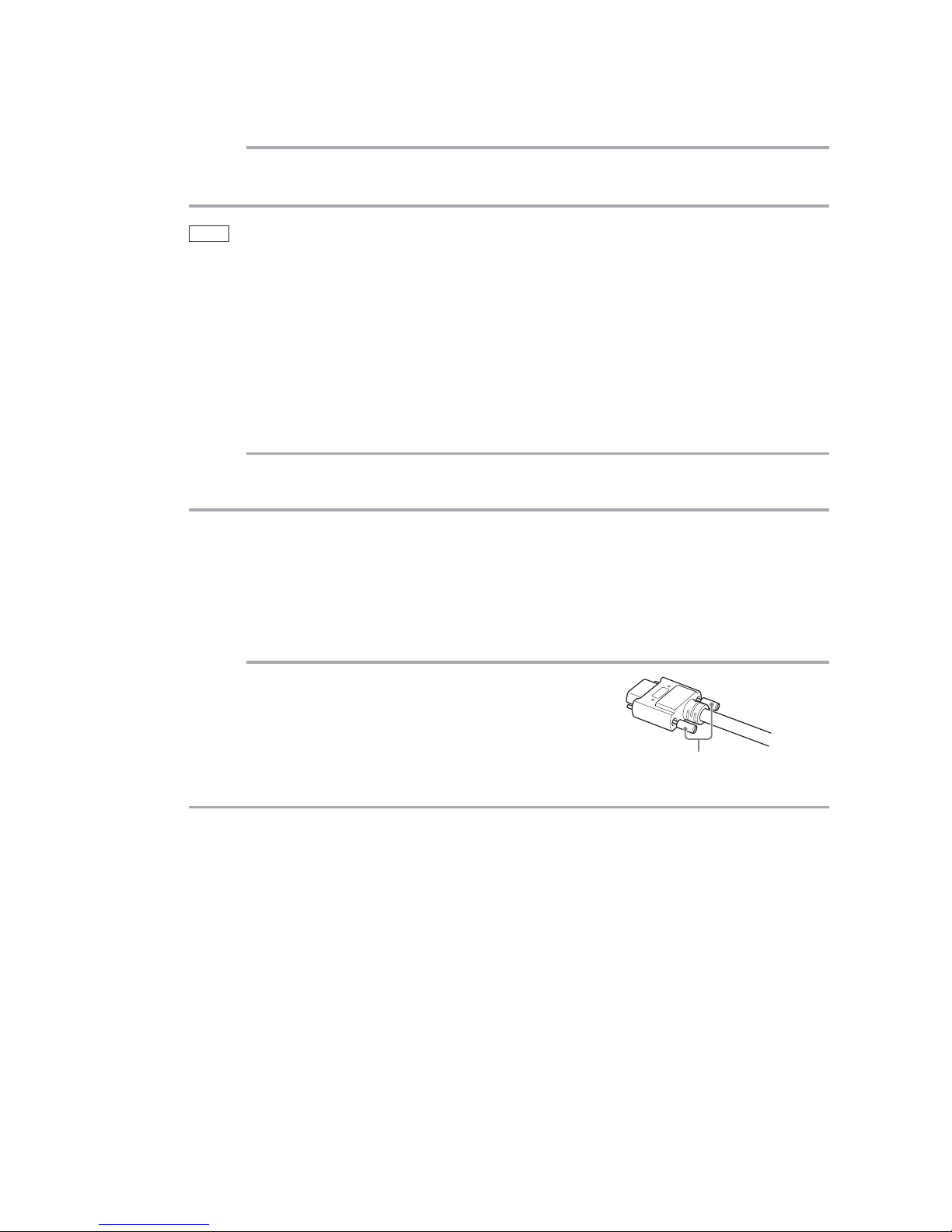
Notes on Camera Link cable connections
Secure the locking screws on the connector manually, and do not
use a driver. Do not secure the screws too tightly. Doing so may
wear down the screw threads on the camera. (Tightening torque:
0.291±0.049 N·m or less)
Notes on attaching the lens
Avoiding dust particles
When attaching the lens to the camera, stray dust and other particles may adhere to the sensor
surface and rear surface of the lens. Be careful of the following when attaching the lens.
• Work in a clean environment.
• Do not remove the caps from the camera and lens until immediately before you attach the
lens.
• To prevent dust from adhering to surfaces, point the camera and lens downward and do not
allow the lens surface to come into contact with your hands or other objects.
• Always use a blower brush to remove any dust that adheres.
Never use your hands or cloth, blow with your mouth, or use other methods to remove
dust.
Phenomena specific to CMOS image sensors
The following phenomena are known to occur on cameras equipped with CMOS image sensors. These
do not indicate malfunctions.
• Aliasing
When shooting straight lines, stripes, and similar patterns, vertical aliasing (zigzag distortion) may
appear on the monitor.
• Blooming
When the camera is pointed at scenes containing very bright areas or strong light sources, some
pixels on the CMOS image sensor may accumulate more than the maximum charge allowed, causing
the excess charge to overflow into the surrounding pixels. While this "blooming" affects image quality,
it does not affect the operation of the camera.
• Fixed pattern noise
When shooting dark objects in high-temperature conditions, fixed pattern noise may occur
throughout the entire video monitor screen.
• Defective pixels
Defective pixels (white and black pixels) of the CMOS image sensor are minimized at the factory
according to shipping standards. However, as this phenomenon can be affected by the ambient
temperature, camera settings (e.g., high sensitivity and long exposure), and other factors, be sure to
operate within the camera’s specified operating environment.
Notes on exportation
When exporting this product, please follow the export regulations of your country or region.
Secure manually.
Do not secure too tightly.
Usage Precautions
GO-5101M-PMCL / GO-5101C-PMCL
Page 7

— 7 —
GO-5101M-PMCL / GO-5101C-PMCL
Features
The GO-5101M-PMCL/GO-5101C-PMCL is an industrial progressive scan camera equipped with a
2/3-inch global shutter CMOS image sensor with 5.1 effective megapixels (2464 × 2056). The unit is
compact and lightweight in design and is equipped with Camera Link Ver. 2.0 compatible interface.
The GO-5101M-PMCL produces monochrome output while the GO-5101C-PMCL produces Bayer output.
Compact and lightweight
The unit’s compact size (approx. 29 × 29 × 41.5 mm, excluding lens mount) and lightweight design
(approx. 46 g) allows for easy assembly and installation.
Camera Link Ver. 2.0 compatible interface
• High-speed transfer at up to 850 MByte/s of uncompressed data, the ideal format for image
processing.
• Maximum cable length of 10 m.
• Support for PoCL (Power over Camera Link) allowing you to supply power to the camera via the
Camera Link cable.
Note
To power the camera via Camera Link, the frame grabber board you are using must support PoCL. You can also
supply power via the 4-pin connector. A separate power supply and/or conversion cable (not supplied) is required.
Output formats
You can choose from 8-bit, 10-bit, and 12-bit* output for both monochrome and Bayer.
* As the color camera cannot perform white balance when using 12-bit output, perform white balance on the
application.
High frame rate
The GO-5101M-PMCL and GO-5101C-PMCL are both capable of frame rates of up to 35.6 fps (8-bit
format) for full 5.1-megapixel output. Even faster frame rates can be achieved when binning is utilized
(GO-5101M-PMCL only) or when a smaller ROI (region of interest) is specified.
ALC (automatic level control) function
Combine the automatic gain control and automatic exposure control functions to allow handling of
changes in various brightnesses.
Variety of pre-process functions
• LUT (lookup table)
For programmable control over gamma and contrast.
• Gamma correction
Gamma can be set to 0.45, 0.60, or 1.0 (off).
• Shading correction (flat field and color shading)
Non-uniformity (i.e., shading) in the amount of light generated by the lens and lighting equipment can
be corrected.
• Bayer white balance (GO-5101C-PMCL only)
White balance can be automatically adjusted continuously. It can also be adjusted manually using R,
and B gain.
Page 8
— 8 —
GO-5101M-PMCL / GO-5101C-PMCL
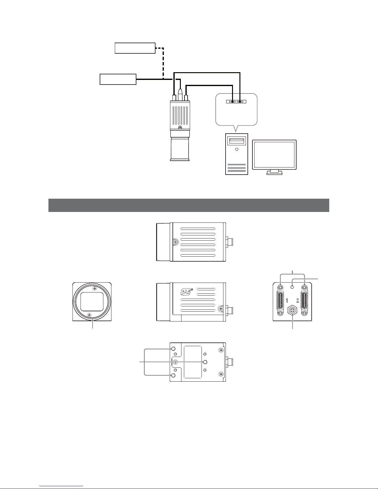
Connection example:
External trigger
AC adapter
Camera
Frame grabber
board
Computer
Parts Identification
②
③
④
①
⑤
1
Lens mount (C-mount)
Mount a C-mount lens, microscope adapter, etc. here.
Before mounting a lens, be sure to refer to “Step 2: Connecting Devices” (page 13) and confirm the
precautions for attaching a lens and the supported lens types.
Page 9
— 9 —
GO-5101M-PMCL / GO-5101C-PMCL
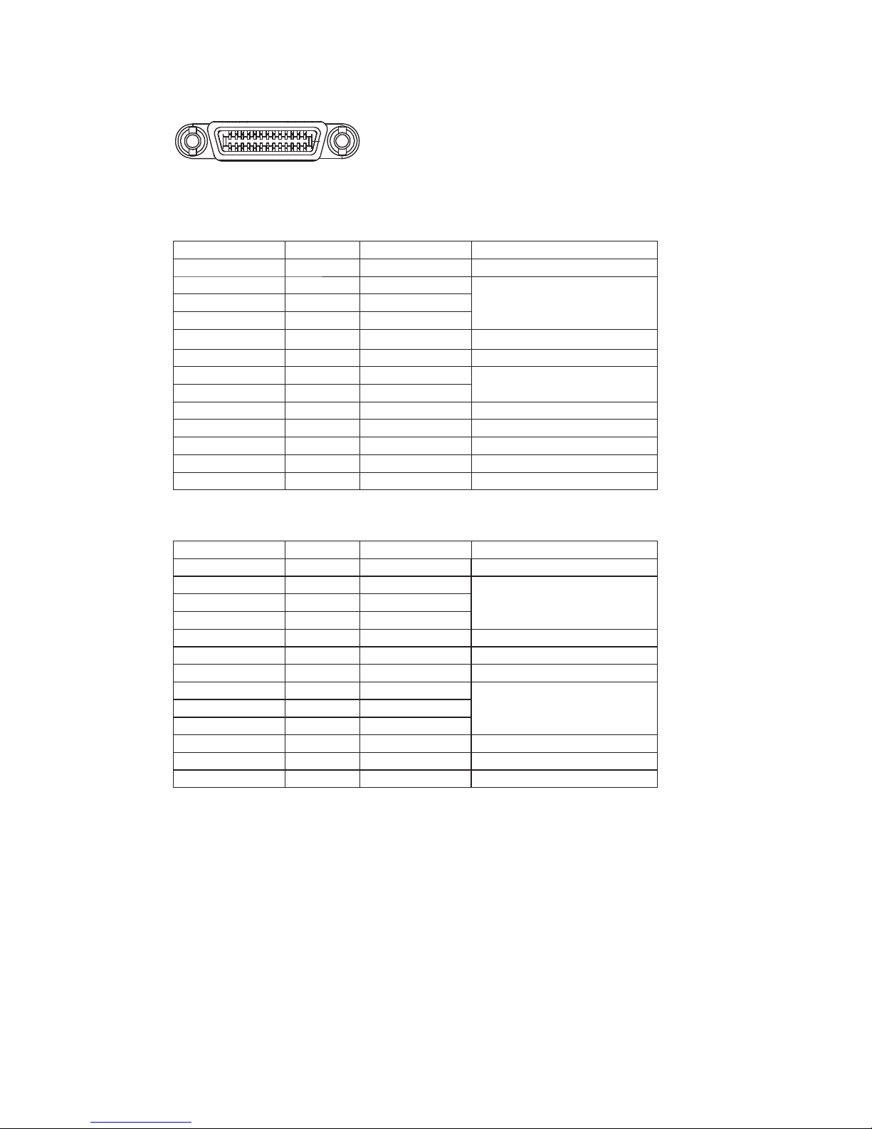
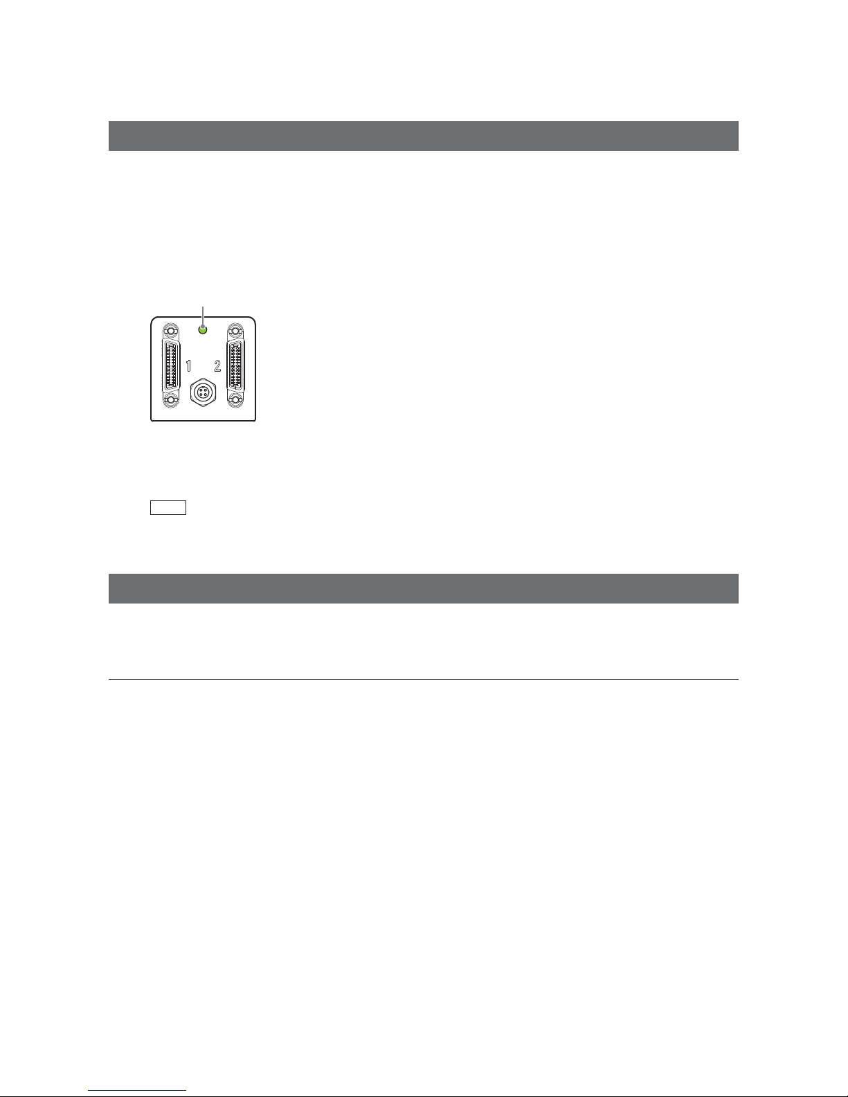
2 Mini Camera Link connector
Connect a cable that is compatible with Mini Camera Link (SDR) connectors here.
13
14
1
26
Camera side: HONDA HDR-EC26FYTG2-SL+
Port 1
Pin No. Input/output Signal Description
1, 26 Power Power
2(–), 15(+) Out X_OUT0 Data out
3(–), 16(+) Out X_OUT1
4(–), 17(+) Out X_OUT2
5(–), 18(+) Out X_Clk CL Clock
6(–), 19(+) Out X_OUT3 Data out
7(+), 20(–) In SerTC (RxD) LVDS Serial Control
8(–), 21(+) Out SerTFG (TxD)
9(–), 22(+) In CC1 (Trigger) JAI standard trigger
10(+), 23(–) In CC2 (Reserved)
11, 24 N.C
12, 25 N.C
13, 14 Shield Power Return
Port 2
Pin No. Input/output Signal Description
1, 26 Power Power
2(–), 15(+) Out Y_OUT0 Data out
3(–), 16(+) Out Y_OUT1
4(–), 17(+) Out Y_OUT2
5(–), 18(+) Out Y_Clk CL Clock
6(–), 19(+) Out Y_OUT3 Data out
7(+), 20(–) N.C
8(–), 21(+) Out Z_OUT0 Data out
9(–), 22(+) Out Z_OUT1
10(+), 23(–) Out Z_OUT2
11(–), 24(+) Out Z_Clk CL Clock
12(–), 25(+) Out Z_OUT3 Data out
13, 14 Shield Power Return
Page 10
— 10 —
GO-5101M-PMCL / GO-5101C-PMCL
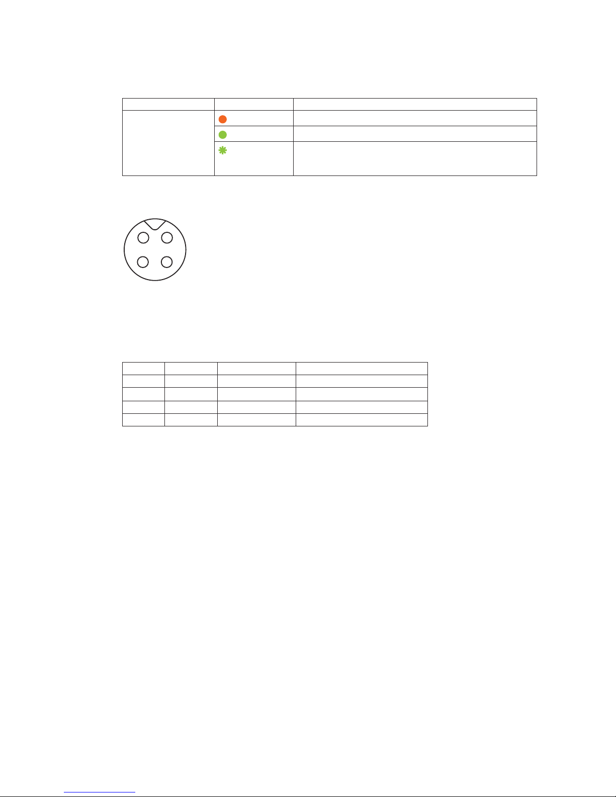
3 Power/trigger LED
Indicates the power and trigger input status.
LED status and camera status
LED Light Status
Power / trigger LED
Lit amber
Camera initializing.
Lit green
Operational and no triggers being input.
Blinking green
Operational and triggers being input.
The blinking interval is not related to the actual input interval
of the external trigger.
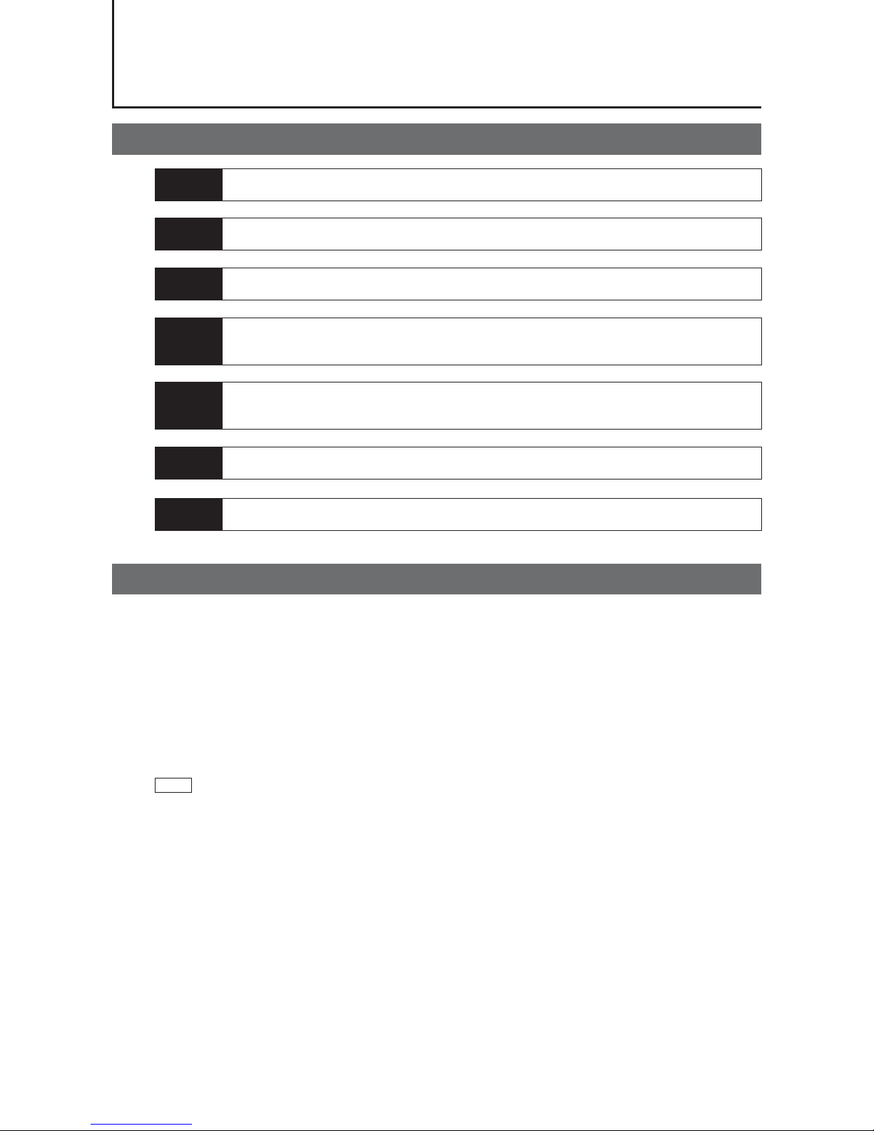
4 DC IN / trigger IN connector ( 4-pin round)
Connect the cable for a VA-044F or PD-4P-GO Power Supply (optional) or for DC IN / trigger IN here.
1
2
3
4
Compatible connectors
Camera side: 09-3111-81-04 (Binder)
Cable side: 79-3108-52-04 (Binder) AWG 26
or
79-3108-32-04 (Binder) AWG 24
Pin No. Input/output Signal Description
1 Power In DC (+12 V) In DC 12 V to 24 V +/– 10%
2 In TTL In Line 4
3 Out TTL Out Line 1
4 Out Power GND COMMON GND
5 Camera locking screw holes (M3, 3 mm depth)
Use these holes when attaching an MP-43 tripod adapter plate (optional) or mounting the camera
directly to a wall or other structural system.
• The smaller holes (×4) are M2 with a depth of 3 mm.
Page 11
— 11 —
GO-5101M-PMCL / GO-5101C-PMCL
Preparation
Preparation Process
Step 1 Installing the Software (first time only)
Install the software for configuring and controlling the camera (JAI SDK) on the computer.
Step 2 Connecting Devices
Connect the lens, Camera Link cable, AC adapter, computer, and other devices.
Step 3 Verifying the Camera’s Connection Status
Verify whether the camera is ready for use via the LEDs at the rear of the camera.
Step 4 Configuring Initial Settings for the Camera
• Configure the output format.
• Configure settings related to the exposure and external trigger.
Step 5 Adjusting the Image Quality
• Adjust the gain and white balance.
• Adjust the exposure (shutter).
Step 6 Configuring Various Other Settings
Configure various other settings as necessary.
Step 7 Saving the Settings
Save the current setting configurations in user memory.
Step 1: Installing the Software (first time only)
When using the camera for the first time, install the software for configuring and controlling the camera
( JAI SDK) on the computer.
When you install JAI SDK, JAI Camera Control Tool will also be installed.
1
Download the “JAI - Getting Started Guide” and JAI SDK from the JAI website.
URL: http://www.jai.com/en/support/download-jai-software
2
Refer to the “JAI - Getting Started Guide,” and install JAI SDK on the computer.
The computer will restart when installation is complete.
Note
When the JAI SDK is installed, a camera driver for the interface is also part of the default installation. This Vision
Filter Driver is added to every NIC/port on the host computer. As the driver is also added to the NIC/port for
Internet connection, it may, on some systems, affect Internet access speed. If you think your Internet speed is
affected, configure the following settings to disable the filter driver on that port.
u
Open [Control Panel] [Network and Internet] [Connect to a network], and right-click the port
used for Internet connection to open the properties dialog box.
Page 12
— 12 —
GO-5101M-PMCL / GO-5101C-PMCL
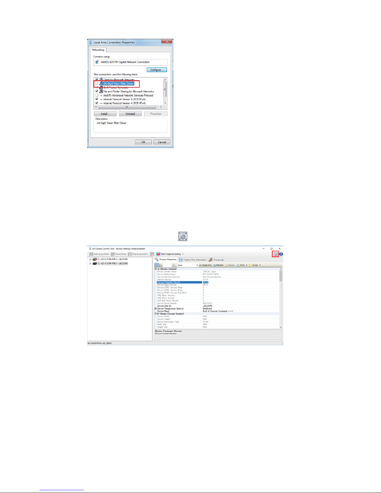
v
Clear the [JAI Vision Filter Driver] checkbox, and save.
3
Verify the settings for using Camera Link.
The GO-5101-PMCL supports GenICam and Gen-CP. Check the following settings when
controlling the camera via JAI SDK.
Checking the frame grabber board's settings
Settings must be configured on the frame grabber board to enable Gen-CP support.
For details, refer to the operating instructions for each board.
Checking JAI SDK's settings
u
Start JAI Control Tool, and click the (Settings) icon at the top right.
v
Check that the [JAI_GenCP_Camera_Link] and [Camera Link Transport Layer] settings are
configured as follows.
Page 13
— 13 —
GO-5101M-PMCL / GO-5101C-PMCL
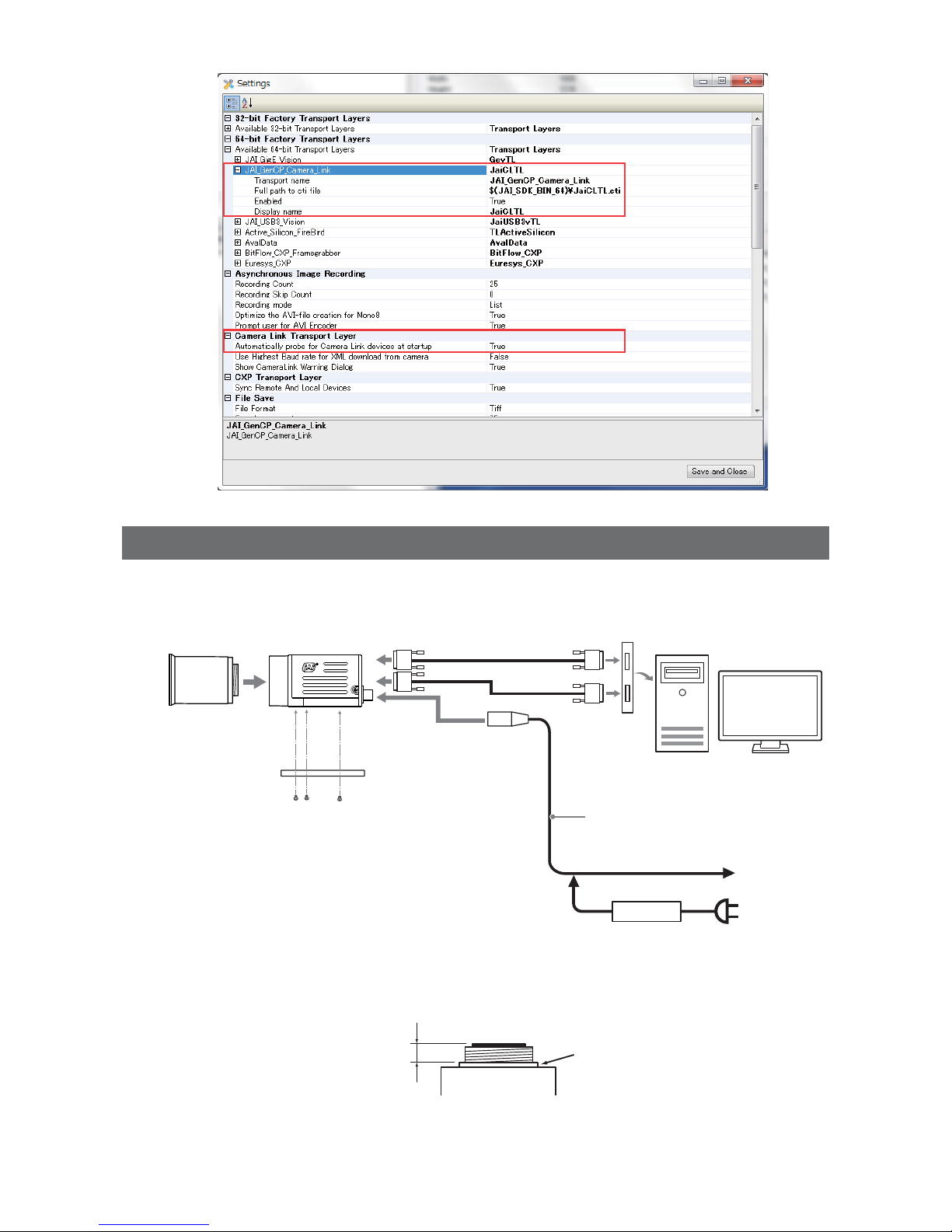
Step 2: Connecting Devices
Connect the lens, Camera Link cable, AC adapter, and other devices.
Attach the lens in a clean environment to prevent dust from adhering to the unit.
Camera body
2
Direct connection
(or MP-43 tripod adapter plate)
6
DC IN / trigger IN
connection cable (not supplied)
1
Lens
3
Camera Link cable
4
Frame grabber board
5
Computer
to external
trigger
or
7
AC adapter (not supplied)
1
Lens
• C-mount lenses with lens mount protrusions of 9 mm or less can be attached.
9 mm or less
Lens mount protrusion
Lens
• The diagonal of the camera’s CMOS image sensor is 11 mm, the size of standard 2/3-inch lenses.
Page 14
— 14 —
GO-5101M-PMCL / GO-5101C-PMCL
To prevent vignetting and to obtain the optimal resolution, use a lens that will cover the 11 mm
diagonal. Some lens manufacturers offer lenses with an 11 mm format. If not, a 2/3-inch lens is
recommended.
Caution
• The maximum performance of the camera may not be realized depending on the lens.
• Attaching a lens with a mount protrusion of 9.1 mm or longer may damage the lens or camera.
Note
The following formula can be used to estimate the focal length.
focal length = WD / (1 + W/w)
WD: Working distance (distance between lens and object)
W: Width of object
w: Width of sensor (sensor width is 8.5 mm on this camera)
2
Direct connection (or MP-43 tripod adapter plate)
When mounting the camera directly to a wall or other device, use screws that match the locking
screw holes on the camera. (Large: M3, small: M2, depth: 3 mm)
Use the supplied screws to attach the tripod adapter plate.
Caution
For heavy lenses, be sure to support the lens itself. Do not use configurations in which its weight is supported
by the camera.
3
Camera Link cable
Connect the Camera Link cable to the Mini Camera Link connector.
• Use a cable that supports the Camera Link standard and is compatible with Mini Camera Link
(SDR) connectors.
• Refer to the specifications of the cable for details on its bend radius.
• For details on the cable, see “2 Mini Camera Link connector” (page 9).
Caution
Secure the locking screws on the connector manually, and do not use a
driver. Do not secure the screws too tightly. Doing so may wear down the
screw threads on the camera. (Tightening torque: 0.291±0.049 N·m or
less)
4
Frame grabber board
Refer to the operating instructions of the frame grabber board, and configure settings on the
computer as necessary.
5
Computer
Use a computer that meets the following requirements.
Operating system (OS):
Microsoft Windows 7/8 32-bit/64-bit edition
CPU: Intel Core i3 or higher
Memory:
Windows 7/8 32-bit edition: DDR3, 4 GB or higher
Windows 7/8 64-bit edition: DDR3, 8 GB or higher
Graphics card: PCI-Express 3.0 or higher
6
DC IN / trigger IN connection cable
7
AC adapter (power supply) (if necessary)
Connect the AC adapter and the round connector of the connection cable to the DC IN / trigger IN
Secure manually.
Do not secure too tightly.
Page 15
— 15 —
GO-5101M-PMCL / GO-5101C-PMCL
connector on the camera.
The AC adapter is not required when using PoCL.
Step 3: Verifying the Camera’s Connection Status
When the necessary devices are connected and power is supplied to the camera, the power / trigger
LED at the rear of the camera lights amber, and initialization of the camera starts.
When initialization is complete, the power / trigger LED lights green.
Verify whether power is being supplied to the camera and whether the camera is operational by
checking the rear LED.
Lit green
During normal status
For details on how to read the LEDs, see “LED status and camera status” (page 10) in the “Parts
Identification” section.
Note
If the power / trigger LED does not switch to green within minutes of supplying power, check the Camera Link
cable and other connections.
Step 4: Configuring Initial Settings for the Camera
Start Control Tool, connect the camera to the frame grabber board, and configure initial settings for the
output format, exposure, external trigger, etc.
Connecting the Camera to the Control Tool
1
Start JAI Control Tool.
Cameras connected to the frame grabber board are detected, and a window appears. If they do
not appear, right-click inside the window and select [Search for Cameras].
2
Select the camera you want to configure.
3
Check that the settings of the selected camera are displayed.
Page 16
— 16 —
GO-5101M-PMCL / GO-5101C-PMCL
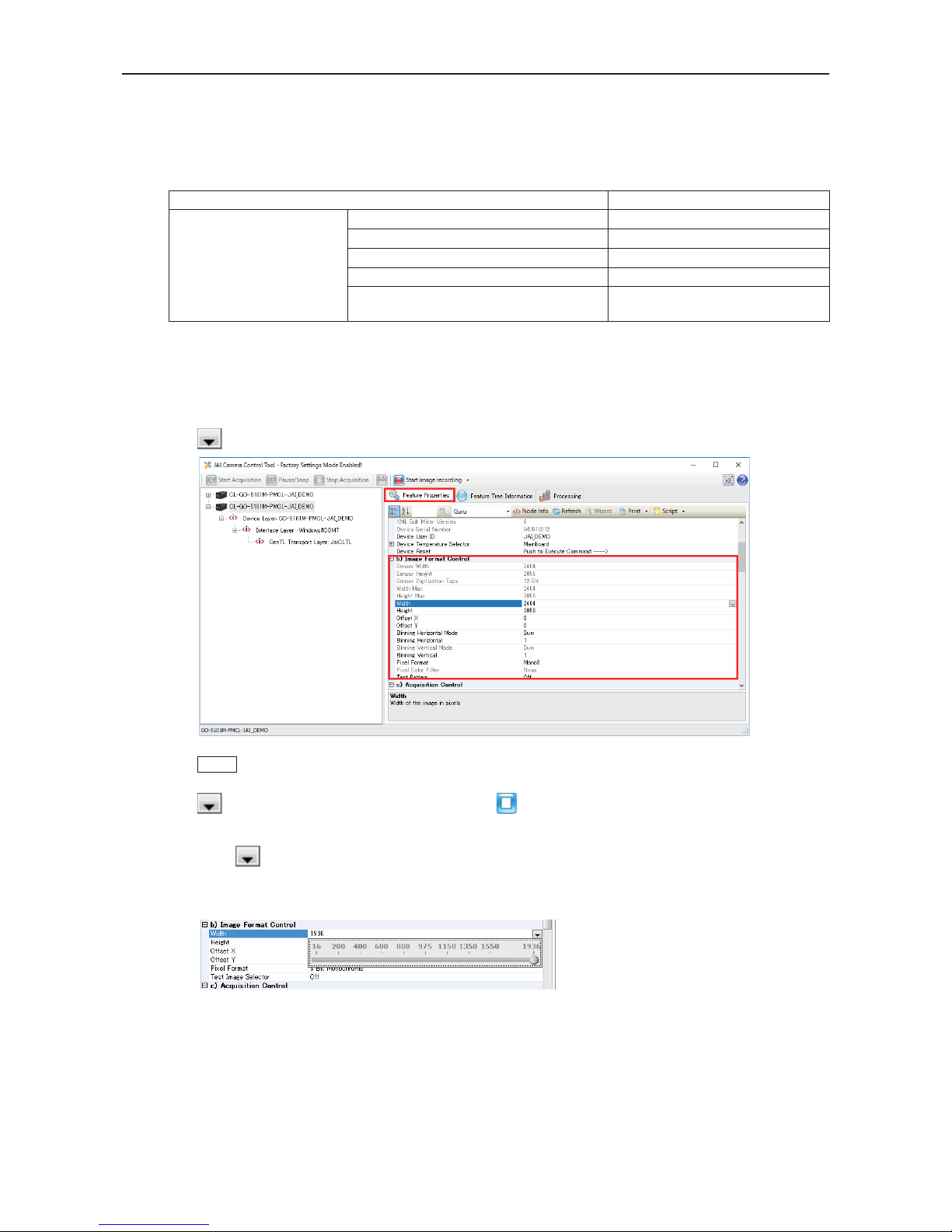
Configuring the Output Format
Configure the size, position, and pixel format of the images to be acquired.
The factory settings are as follows. Change the settings as necessary.
Factory default values
Item Default value
Image Format Control Width 2464 (pixels)
Height 2056 (pixels)
Offset X (horizontal position) 0 (pixels)
Offset Y (vertical position) 0 (pixels)
Pixel Format GO-5101M-PMCL: Mono8
GO-5101C-PMCL: BayerRG8
You can specify the image acquisition area. For details, see “ROI (Regional Scanning Function)” (page 38).
1
Select the [Feature Properties] tab, and select the item you want to configure under [Image
Format Control].
when a configurable item is selected.
Note
Settings can only be changed when image acquisition on the camera is stopped. If an item is grayed out and
does not appear even when you select it, click (Stop Acquisition) to stop image acquisition.
2
Click and change the setting value.
Example: When changing [Width]
Page 17

— 17 —
GO-5101M-PMCL / GO-5101C-PMCL
Example: When changing [Pixel Format]
Note
Direct entry of numerical and text values is possible for some setting items.
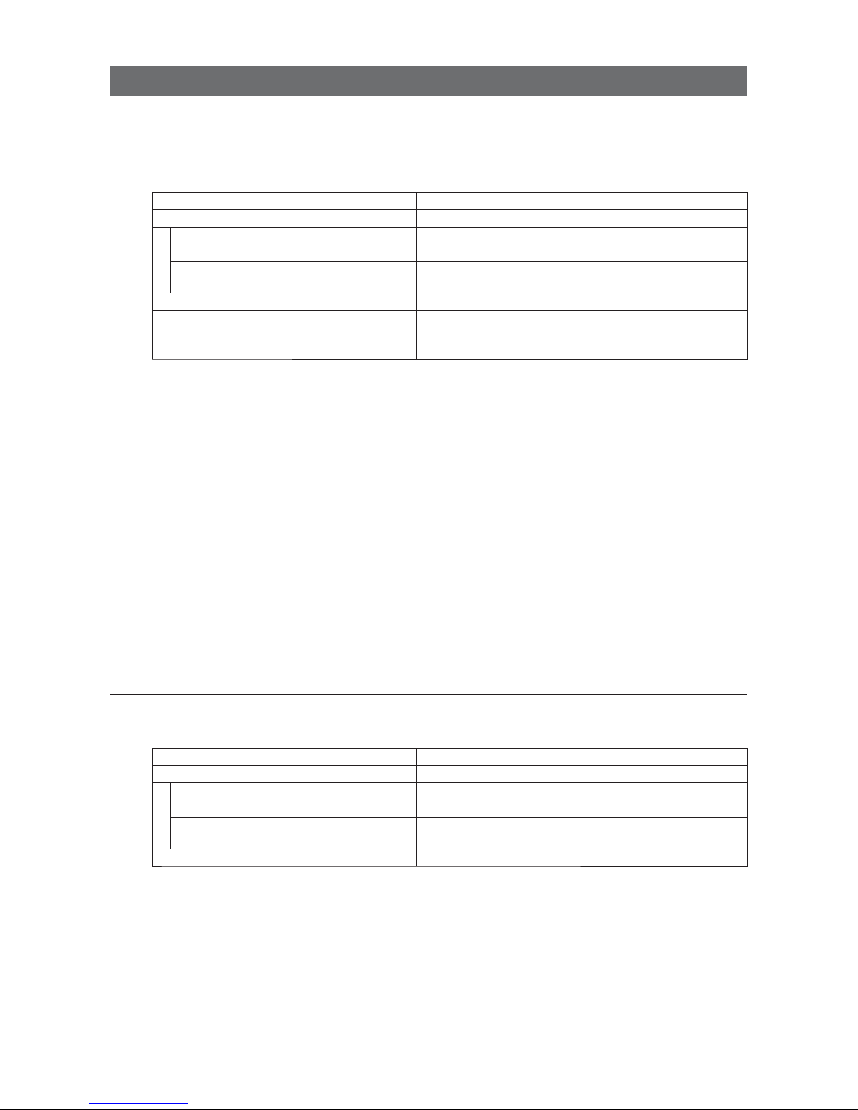
Configuring Exposure and External Trigger Settings
Configure settings related to exposure control methods and trigger control.
The factory settings are as follows. Change settings as necessary, according to the intended purpose
or application.
Factory default values
Item Default value
Trigger Selector (trigger operation) Frame Start
Trigger Mode Off
Trigger Source (trigger signal source) Line7-CC1
Trigger Activation (trigger polarity) Rising Edge (rising edge of input signal)
Exposure Mode Timed (control via exposure time)
Exposure Time 27847 (µs)
Exposure Auto* Off
* This item is only enabled when [Exposure Mode] is set to [Timed].
Caution
When [Exposure Mode] is set to [Off], [Trigger Mode] cannot be set to [On]. Other settings may also be restricted
depending on the exposure mode, so be sure to set the exposure mode before configuring the trigger settings.
Configure the settings by expanding [Acquisition Control] and configuring the following items.
Page 18
— 18 —
GO-5101M-PMCL / GO-5101C-PMCL
Control via External Triggers
When Controlling the Exposure Time Using Specified Exposure Times
Configure the settings as follows.
Item Setting value / selectable range
Trigger Selector (trigger operation) Frame Start
Trigger Mode On
Trigger Source (trigger signal source) Any
Trigger Activation (trigger polarity) Rising Edge (rising edge of input signal), Falling Edge (falling
edge of input signal)
Exposure Mode Timed (control via exposure time)
Exposure Time Varies depending on the Tap Geometry and CL Pixel Clock
settings.
Exposure Auto Off, Continuous
1
Set [Exposure Mode] to [Timed].
([Timed] is the default setting.)
2
Specify the exposure time in [Exposure Time].
The setting value for the exposure time can only be changed when [Exposure Auto] is set to [Off].
If [Exposure Auto] is set to [Continuous], temporarily set it to [Off] before changing the exposure
time.
3
Set [Trigger Selector] to [Frame Start].
([Frame Start] is the default setting.)
4
Set [Trigger Mode] to [On].
5
If necessary, change the [Trigger Source], [Trigger Activation], and [Exposure Auto]
settings.
When Controlling the Exposure Time using the Pulse Width of the Trigger Input Signal
Configure the settings as follows.
Item Setting value / selectable range
Trigger Selector (trigger operation) Frame Start
Trigger Mode On
Trigger Source (trigger signal source) Any
Trigger Activation (trigger polarity) Level High (high-level duration), Level Low (low-level
duration)
Exposure Mode Trigger Width (control via trigger width)
1
Set [Exposure Mode] to [Trigger Width] .
When you select [Trigger Width], [Trigger Mode] will automatically be set to [On].
2
Set [Trigger Selector] to [Frame Start].
([Frame Start] is the default setting.)
3
If necessary, change the [Trigger Source] and [Trigger Activation] settings.
Page 19

— 19 —
GO-5101M-PMCL / GO-5101C-PMCL
Control Without External Triggers
When Controlling the Exposure Time Using Specified Exposure Times
Configure the settings as follows.
Item Setting value / selectable range
Trigger Selector (trigger operation) Frame Start
Trigger Mode Off
Exposure Mode Timed (control via exposure time)
Exposure Time Varies depending on the Tap Geometry and CL Pixel Clock
settings.
Exposure Auto Off, Continuous
1
Set [Exposure Mode] to [Timed].
([Timed] is the default setting.)
2
Specify the exposure time in [Exposure Time].
The setting value for the exposure time can only be changed when [Exposure Auto] is set to [Off].
If [Exposure Auto] is set to [Continuous], temporarily set it to [Off] before changing the exposure
time.
3
Set [Trigger Mode] to [On].
4
If necessary, change the [Exposure Auto] setting.
When not Controlling the Exposure Time
Configure the settings as follows.
Item Setting value / selectable range
Exposure Mode Off
The exposure will be performed with an exposure time equal to 1 / frame rate.
Step 5: Adjusting the Image Quality
Adjust the image quality using the gain and white balance (GO-5101C-PMCL only) functions.
To adjust the image quality
The display level must be changed from [Beginner] to [Guru].
Page 20

— 20 —
GO-5101M-PMCL / GO-5101C-PMCL
Adjusting the Gain
Adjust the sensitivity via the analog gain (i.e., master gain).
For details on gain control, see “Gain Control” (page 33) in the “Main Functions” section.
■ Manual adjustment
1
Expand [Analog Control], and set [Gain Auto] to [Off].
([Off] is the default setting.)
2
Configure the gain.
u
Expand [Analog Control], and select the gain you want to configure in [Gain Selector].
• For the GO-5101M-PMCL, only [Analog All] (master gain) can be configured.
• For the GO-5101C-PMCL, [Analog All] (master gain), [Digital Red] (digital R gain), and
[Digital Blue] (digital B gain) can be configured individually.
v
Configure the gain value in [Gain].
• [Analog All] (master gain) can be set to multiple (x1 to x16) of Analog Gain. The resolution is
set in x0.01 steps (0.005 dB to 0.08 dB depending on the setting value). Values are
configured by multipliers. For example, the values set for x1 and x16 are 100 and 1600
respectively.
• For the GO-5101C-PMCL, the [Digital Red] (digital R gain) and [Digital Blue] (digital B gain)
can be set to a value from x0.45 to x5.62 (–7 dB to +15 dB) the [Digital All] (master gain)
value. The resolution is set in x0.01 dB steps.
Adjusting the White Balance (GO-5101C-PMCL only)
Adjust the white balance using R and B gain. The white balance can also be adjusted automatically.
■ Manual white balance adjustment
1
Expand [Analog Control], and set [Balance White Auto] to [Off].
([Off] is the default setting.)
2
Select the gain to configure in [Gain Selector], and set the gain value in [Gain].
■ Automatic white balance adjustment
1
Place a white sheet of paper or similar object under the same lighting conditions as the
intended subject, and zoom in to capture the white.
White objects near the subject, such as a white cloth or wall, can also be used.
Be sure to prevent the high-intensity spot lights from entering the screen.
2
Select the [Balance White Auto] tab, and click [Continuous] or [Once] depending on your
intended application.
The white balance is automatically adjusted.
Page 21

— 21 —
GO-5101M-PMCL / GO-5101C-PMCL
Adjusting the Black Level
1
Expand [Analog Control], and select the black level you want to configure in [Black Level
Selector].
For the GO-5101M-PMCL, only [Digital All] (master black) can be configured.
For the GO-5101C-PMCL, [Digital All] (master black), [Digital Red] (digital R), and [Digital Blue]
(digital B) can be configured individually.
2
Specify the adjustment value in [Black Level].
Step 6: Configuring Various Other Settings
See “Settings List” (page 46) and configure settings as necessary.
Step 7: Saving the Settings
The setting values configured in Control Tool will be deleted when the camera is turned off. By saving
current setting values to user memory, you can load and recall them whenever necessary. You can
save up to three sets of user settings (User Set1 to 3) in the camera.
User memory Temporary memory
Current
setting
values
Control
Tool
Save
User Set1
User Set2
User Set3
Note
Changes to settings are not saved to the computer (Control Tool).
Page 22

— 22 —
GO-5101M-PMCL / GO-5101C-PMCL
■ To save user settings
1
Stop image acquisition.
2
Expand [User Set Control], and select the save destination ([User Set1] to [User Set3]) in
[User Set Selector].
Note
The factory default setting values are stored in [Default] and cannot be overwritten.
3
Select [User Set Save], and click [Execute ‘User Set Save’ Command].
The current setting values are saved as user settings.
■ To load user settings
1
Select the settings to load (User Set1 to User Set3) in [User Set Selector].
2
Select [User Set Load], and click [Execute ‘User Set Load’ Command].
The selected user settings are loaded.
Page 23

— 23 —
GO-5101M-PMCL / GO-5101C-PMCL
Basic Function Matrix
The combinations of settings for the basic functions that can be used together are as follows.
Exposure Mode
Frame Start Trigger
Binning Vertical*
1
Binning Horizontal*
1
Exposure Time
ROI
Balance White
Auto*
2
Gain Auto
Exposure Auto
Sequencer
Trigger
Sequencer
Mode
Command
Sequencer
Mode
Off Off 1 × 1 (Off) ×
×× ×
1 × 2 ×
−
×× ×
2 × 1 ×
−
×× ×
2 × 2 ×
−
×× ×
Timed Off 1 × 1 (Off)
×
1 × 2
−
×
2 × 1
−
×
2 × 2
−
×
Timed (EPS) On 1 × 1 (Off)
1 × 2
−
2 × 1
−
2 × 2
−
Trigger Width On 1 × 1 (Off) ×
×× ×
1 × 2 ×
−
×× ×
2 × 1 ×
−
×× ×
2 × 2 ×
−
×× ×
*1 Operates only on the GO-5101M-PMCL
*2 Operates only on the GO-5101C-PMCL
Page 24

— 24 —
GO-5101M-PMCL / GO-5101C-PMCL
Main Functions
GPIO ( Digital Input/Output Settings)
The unit can input/output the following signals to and from external input/output connectors.
External output TTL Out (Line1) DC IN / trigger IN connector (4-pin round)
External input TTL IN (Line4) DC IN / trigger IN connector (4-pin round)
CC1 (Line7) Camera Link cable
These signals can be used as triggers and other necessary signals within the camera or as signals
output from the camera to the system, such as those used for lighting equipment control.
In addition, a pulse generator for generating custom pulses and a NAND module for performing logic
operations are built into the camera. The two can be used together for a variety of purposes, such as
noise removal for trigger signals and phase adjustment for pulse outputs.
Such functions are generally referred to as GPIO functions.
Signals are selected as follows.
• When using external signals or the signals of each GPIO module as trigger signals:
Select in [Trigger Selector] > [Trigger Source].
• When selecting the signals to use for external outputs:
Select in [Line Selector] > [Line Source].
• When selecting the input signal for the NAND logic line:
Select in [Line Selector] > [Line Source].
• When selecting the clear signal for [Pulse Generator]:
Select in [Pulse Generator Selector] > [Pulse Generator Clear source].
GPIO block diagram
NAND Logic
NAND Logic
Pulse
Generator
Trigger Selector
PulseGenerator
Selector
Line Selector
Cross point switch
External input
Camera internal signal
User control signal
GPIO module signal
Trigger signal
External output
Signal to the GPIO module
Page 25

— 25 —
GO-5101M-PMCL / GO-5101C-PMCL
Valid Input/Output Combinations
The following signals can be used as sources for each output destination (Trigger Selector, Line
Selector, Pulse Generator Selector).
You can also connect two different sources to NAND paths in the GPIO and reuse the signal generated
there as a source for a different selector.
The combinations of source signals and output destinations are indicated in the following.
Selector
(Cross point
switch output)
Source signal
(Cross point
switch input)
Output destination
Trigger
Selector
Line Selector
Pulse
Generator
Selector
Frame Start
Line1 Output Source
Nand Gate 0 In 1
Nand Gate 0 In 2
Nand Gate 1 In 1
Nand Gate 1 In 2
Pulse Generator
Clear Source
Signals to use as output
LOW
HIGH
Software
ЧЧЧЧЧ Ч
Line 4 TTL In
Line 7 CC1
Pulse Generator 0
×
User Output 0
User Output 1
NAND 0 Out
××
NAND 1 Out
××
Exposure Active
×
Frame Active
×
Frame Trigger Wait
×
FVAL
×
LVA L
ЧЧЧЧЧЧ
Trigger
Source
Line Source
Pulse
Generator
Clear Source
Use
: Indicates default values for each selector. “Factory default values” (page 17) shows the
default values for [Frame Start].
Camera Output Formats
The GO-5101-PMCL supports a variety of output formats.
The following tap geometries are supported.
The settings on the frame grabber board must be configured to match the tap geometry setting on the
camera. For details configuring frame grabber board settings, refer to the operating instructions for
each board.
Tap Geometry CL Configuration Video Process Bypass Off Video Process Bypass On
1X2-1Y Base bit: 8/10 bit: 8/10/12
1X3-1Y Base bit: 8 bit: 8
1X3-1Y Medium bit: 10 bit: 10/12
1X4-1Y Medium bit: 8/10 bit: 8/10/12
Page 26

— 26 —
GO-5101M-PMCL / GO-5101C-PMCL
■ 1X2-1Y
1X2-1Y is a 2-tap output format as defined in GenICam tap geometry.
■ 1X3-1Y
1X3-1Y is a 3-tap output format as defined in GenICam tap geometry.
Page 27

— 27 —
GO-5101M-PMCL / GO-5101C-PMCL
■ 1X4-1Y
1X4-1Y is a 4-tap output format as defined in GenICam tap geometry.
3
4
■ Cable length reference
The following is a reference for the length of cable you can use based on the Camera Link clock*1.
CL Pixel Clock [MHz] CL cable length
37.125 10 m
74.25 7 m
84.85 3 m
*1 The length of cable you can use will also vary depending on type and maker.
Acquisition Control (Image Acquisition Controls)
Perform operations and configure settings related to image capture in [Acquisition Control].
On the GO-5101-PMCL, acquisition control always operates in [Continuous] mode.
Changing the Frame Rate
When [Trigger Mode] is disabled, you can change the frame rate in [Acquisition Frame Rate].
Note
• The shortest frame period varies depending on the ROI, pixel format, and binning mode selected. The longest
frame period is 0.125 Hz (8 sec.).
• When [Trigger Mode] is enabled, the [Acquisition Frame Rate] setting is disabled.
Page 28

— 28 —
GO-5101M-PMCL / GO-5101C-PMCL
■ Maximum frame rate period formula
During continuous operation ([Frame Start] trigger is [Off] or [Exposure Mode] is [Off])
• Maximum frame rate of sensor
FR_Cont = 1 / {H Period × (Height + 34)}
When the exposure time is longer than the frame interval
• Maximum exposure time at maximum frame rate
MaxExposureTime_TrOlrd = (1 / FR_Cont) - (14 × H Period)
• Exposure time outside of frame interval
NonOverlapExposureTime = ExposureTime - MaxExposureTime_TrOlrd
However, NonOverlapExposureTime calculation results that are 0 or below will be considered as 0.
• Maximum frame rate
FR_ContLongExposure = 1/{(1/FR_Cont) + NonOverlapExposureTime}
When [Frame Start] trigger is [On] and [Trigger OverLap] is [Off]
• Maximum frame rate of sensor
FR_Cont = 1 / {H Period × (Height + 34)}
• Maximum frame rate
FR_TrOloff = 1/{1/FR_Cont) + ExposureTime}
When [Frame Start] trigger is [On] and [Trigger OverLap] is [Readout]
• Maximum frame rate of sensor
FR_Cont = 1 / {H Period × (Height + 34)}
• Exposure time possible within frames
MaxOverlapTime_TrOlrd = (1 / FR_Cont) - (14 × H Period)
• Exposure time outside of frame interval
NonOverlapExposureTime_TrOlrd = ExposureTime - MaxOverlapTime_TrOlrd
However, NonOverlapExposureTime_TrOlrd calculation results that are 0 or below will be considered
as 0.
For TriggerWidth, the trigger pulse is equivalent to ExposureTime.
• Maximum frame rate
FR_TrOlrd = 1 / {(1 / FR_Cont) + NonOverlapExposureTime_TrOlrd}
Full size - Vertical Binning =1(OFF)
Tap Geometry CL Pixel Clock (MHz) H Period [usec] Frame Rate (fps)
1X2-1Y 37.125 33.293 14.3
1X2-1Y 74.25 16.646 28.7
1X2-1Y 84.85 14.613 32.7
1X3-1Y 37.125 22.249 21.5
1X3-1Y 74.25 13.414 35.6
1X4-1Y 37.125 16.700 28.6
1X4-1Y 74.25 13.414 35.6
Page 29

— 29 —
GO-5101M-PMCL / GO-5101C-PMCL
Exposure Mode
The following exposure modes are available on the camera.
Exposure Mode Description
Off Exposure control is not performed (free-running operation).
Timed Mode in which control is performed using exposure time. Acquire images using an
exposure time configured beforehand on an external trigger.
Trigger Width Mode in which control of the exposure time is performed using the pulse width of the
trigger input signal. The exposure time will be the same as the pulse width of the
trigger input signal. This allows long exposure.
The settings for exposure control and triggers are related to each other. Be sure to configure the settings
described in “Configuring Exposure and External Trigger Settings” (page 17).
Image Output Timing
■ Vertical timing
Tap
Geometry
CL
PixelClock
[MHz]
H
Frequency
(KHz)
FVAL
BlankingLine
[A]
FVALValid
Line [B]
Total
FrameLine [C]
Total Frame
Period (msec)
Frame Rate
(Hz)
1X2-1Y
(Full)
37.125 30.036 34 2056 2090 69.6 14.37
74.25 60.073 34 2056 2090 34.8 28.74
84.85 68.433 34 2056 2090 30.5 32.74
1X3-1Y
(Full)
37.125 44.946 34 2056 2090 46.5 21.51
74.25 74.548 34 2056 2090 28.0 35.67
1X4-1Y
(Full)
37.125 59.879 34 2056 2090 34.9 28.65
74.25 74.548 34 2056 2090 28.0 35.67
Page 30

— 30 —
GO-5101M-PMCL / GO-5101C-PMCL
■ Horizontal timing
㩷
㩷
Tap Geometry
CL Pixel
Clock (MHz)
Line
BlankingClock
[A]
LineValid clock
[B]
Total Line clock
[C]
Total Line Period
(usec) [C]
Line Rate (KHz)
[C]
1X2-1Y
(Full)
37.125 4 1232 1236 33.293 30.036
74.25 4 1232 1236 16.646 60.073
84.85 8 1232 1240 14.613 68.433
1X3-1Y
(Full)
37.125 6 820 826 22.249 44.946
74.25 176 820 996 13.414 74.548
1X4-1Y
(Full)
37.125 4 616 620 16.700 59.879
74.25 380 616 996 13.414 74.548
Trigger Control
The camera allows Frame Start trigger controls to be performed via external trigger signals.
The Frame Start trigger allows exposure control via the trigger signal inputs.
The settings for exposure control and triggers are related to each other. Be sure to configure the settings
described in “Configuring Exposure and External Trigger Settings” (page 17).
Shortest Repetition Period for Triggers
The reciprocal of the maximum frame rate is the time required to output one frame. The shortest
repetition periods for triggers cannot be lower than that value.
■ When [Exposure Mode] is [Timed]
Example: When [Trigger Source] is set to [Line 7 - CC1]
• Trigger overlap: Off
FVAL
Readout duration
Next trigger disabled
Next trigger
input enabled
Sensor
Exposure
Trigger
(= Height x Line Period)
EEN
A
B
t1
Page 31

— 31 —
GO-5101M-PMCL / GO-5101C-PMCL
Tap
Geometry
CL Pixel
Clock
(MHz)
Period from
Trigger start
edge to
Exposure
start[A]
(usec)
Period from
Exposure
end to
FVAL
start[B]
(usec)
Max
Exposure
[msec]
Min
Exposure
[usec]
1X2-1Y 37.125 101 851 69.116 34
1X2-1Y 74.25 51 435 34.558 17
1X2-1Y 84.85 45 384 30.336 15
1X3-1Y 37.125 68 573 46.189 23
1X3-1Y 74.25 42 354 27.847 14
1X4-1Y 37.125 51 436 34.669 17
1X4-1Y 74.25 42 314 27.847 14
• Trigger overlap: Readout
FVAL
Sensor
Exposure
Trigger
(= Height x Line Period)
EEN
A
B
C
Readout duration
Next trigger disabled
Next trigger
input enabled
Tap
Geometry
CL Pixel
Clock
(MHz)
Period from
Trigger start
edge to
Exposure
start[A](usec)
Period from
Exposure
end to FVAL
start[B](usec)
Period FVAL
end to next
trigger start[C]
(usec)
Max
Exposure
[msec]
Min
Exposure
[usec]
1X2-1Y 37.125 101 851 851 − Expo
(Current) +
Expo (Next)
69.116 34
1X2-1Y 74.25 51 435 934 − Expo
(Current) +
Expo (Next)
34.558 17
1X2-1Y 84.85 45 384 939 − Expo
(Current) +
Expo (Next)
30.336 15
1X3-1Y 37.125 68 573 906 − Expo
(Current) +
Expo (Next)
46.189 23
1X3-1Y 74.25 42 354 942 − Expo
(Current) +
Expo (Next)
27.847 14
1X4-1Y 37.125 51 436 937 − Expo
(Current) +
Expo (Next)
34.669 17
1X4-1Y 74.25 42 314 952 − Expo
(Current) +
Expo (Next)
27.847 14
Page 32

— 32 —
GO-5101M-PMCL / GO-5101C-PMCL
■ When [Exposure Mode] is [Trigger Width]
Example: When [Trigger Source] is set to [Line 7 - CC1]
• Trigger overlap: Off
FVAL
Sensor
Exposure
Trigger
(= Height x Line Period)
EEN
A
B
t5
D
Readout duration
Next trigger disabled
Next trigger
input enabled
Tap
Geometry
CL Pixel
Clock
(MHz)
Period from
Trigger start
edge to
Exposure
start[A](usec)
Period from
Exposure
end to FVAL
start[B](usec)
Period FVAL
end to next
trigger start[C]
(usec)
Max
Exposure
[msec]
Min
Exposure
[usec]
1X2-1Y 37.125 101 851 851 − Expo
(Current) +
Expo (Next)
69.116 34
1X2-1Y 74.25 51 435 934 − Expo
(Current) +
Expo (Next)
34.558 17
1X2-1Y 84.85 45 384 939 − Expo
(Current) +
Expo (Next)
30.336 15
1X3-1Y 37.125 68 573 906 − Expo
(Current) +
Expo (Next)
46.189 23
1X3-1Y 74.25 42 354 942 − Expo
(Current) +
Expo (Next)
27.847 14
1X4-1Y 37.125 51 436 937 − Expo
(Current) +
Expo (Next)
34.669 17
1X4-1Y 74.25 42 314 952 − Expo
(Current) +
Expo (Next)
27.847 14
• Trigger overlap: Readout
FVAL
Sensor
Exposure
Trigger
(= Height x Line Period)
EEN
A
B
D
Readout duration
Next trigger
disabled
C Next trigger input enabled
Page 33

— 33 —
GO-5101M-PMCL / GO-5101C-PMCL
Tap
Geometry
CL Pixel
Clock
(MHz)
Period from
Trigger start
edge to
Exposure
start[A](usec)
Period from
Exposure
end to FVAL
start[B](usec)
Next trigger
start prohibited
period[C](usec)
Period from
Trigger end
edge to
Exposure
end[D](usec)
Min
Exposure
[usec]
1X2-1Y 37.125 101 851 466 128 34
1X2-1Y 74.25 51 435 233 61 17
1X2-1Y 84.85 45 384 205 53 15
1X3-1Y 37.125 68 573 311 83 23
1X3-1Y 74.25 42 354 188 48 14
1X4-1Y 37.125 51 436 234 61 17
1X4-1Y 74.25 42 314 188 48 14
Gain Control
[Analog All] can be used for gain control for both the monochrome and color camera. [Analog All]
(master gain) uses the sensor's internal gain function and consists of analog gain + digital gain.
Analog gain is used for lower gain, and analog gain + digital gain is used when the gain becomes
high. R and B can be configured individually as digital gain on the GO-5101C-PMCL.
For details on how to configure the settings, see “Adjusting the Gain” (page 20).
The relationship between the gain setting value, gain amplification, and dB value is as follows. For
example, a gain amplification of x5.62 will be 15 dB.
Monochrome
x16
x1
1600
100
24dB
0dB
Gain
setting
value
Gain
amplification
Gain adjustment range (monochrome)
Bayer color
X89.12
X16
X7.15
X5.62
X1
X0.45
1600
0
37876 (X5.62)
0 (X1)
–4533 (X0.45)
R&B
Red
Blue
39dB
-7dB
0dB
24dB
15dB
0dB
–7dB
15dB
0dB
–7dB
15dB
37876 (X5.62)
0 (X1)
–4533 (X0.45)
Gain
setting
value
Master Master
Gain
amplification
Gain setting
value (scaling)
Gain adjustment range (Bayer color)
Page 34

— 34 —
GO-5101M-PMCL / GO-5101C-PMCL
LUT ( Lookup Table)
The LUT function is used to generate a non-linear mapping between signal values captured on the
sensor and those that are output from the camera. You can specify the output curve using 257 setting
points (indexes).
■ To use the LUT function
Configure the settings as follows.
Item Setting value / selectable range Description
JAI LUT Mode LUT Use LUT.
LUT Selector* GO-5101M-PMCL:
Mono
GO-5101C-PMCL:
Red,
Green,
Blue
Select the LUT channel to control.
LUT Index GO-5101M-PMCL: 0 to 256
GO-5101C-PMCL: 0 to 256
Select the LUT index to configure. Indexes represent the
possible pixel values captured on the sensor, from the lowest
value (Index 0) to the highest (Index 256). For example,
Index 0 represents a full black pixel and Index 255
represents a full white pixel.
LUT Value 0 to 4095 Set the LUT output value for the selected index.
* GO-5101C-PMCL only
■ LUT values
LUT values range from 0 at the lowest to 4095 at the highest. Linear interpolation is used to calculate
LUT values between the index points.
4095
Index0
Index1
LUT Value [1]
LUT Value [0]
Index256
Values between points are determined
using the linear interpolation values of
data to the left and right.
Page 35

— 35 —
GO-5101M-PMCL / GO-5101C-PMCL
Gamma Function
The gamma function corrects the output signals from the camera beforehand (reverse correction),
taking into consideration the light-emitting properties of the monitor display.
As the light-emitting properties of the monitor are not linear, the entire image may be darker or the
gradation in the dark areas may be less noticeable when camera outputs are displayed without
processing.
The gamma function can be used to correct the camera signals with an opposite-direction curve and
produce a display that is close to linear.
Example of the light-emitting properties
of the monitor display
■ To use the gamma function
Configure the settings as follows.
Item Setting value / selectable range Description
Gamma 0.45, 0.60, 1.0 (Off) Select the gamma correction value.
JAI LUT Mode Gamma Use gamma.
Note
You can use the LUT function to configure a curve with more detailed points. For details, see “LUT (Lookup Table)”
(page 34).
Defective Pixel Correction Function
Multiple defective pixels that are not adjacent to each other can occur on conventional CMOS sensor
cameras.
This camera features a function that interpolates defective pixels using the surrounding pixels.
Up to 512 pixels can be corrected. Pixel interpolation can be performed via automatic detection or
point-by-point manual settings.
Page 36

— 36 —
GO-5101M-PMCL / GO-5101C-PMCL
■ Automatic detection
Automatic detection can only detect lit defective pixels (i.e., white blemishes).
1
Shield the camera sensor.
If a lens is attached, use the lens cap as a shield, for example.
2
Configure the threshold level for defective pixel detection.
Specify the threshold value for the blemishes to be detected using the [JAI Custom Control
Blemish] - [Blemish Detect Threshold] setting.
The threshold value is specified as a percentage.
The default setting is "10" with 10% of the full scale (100%) specified as the threshold value.
3
Execute [Blemish Detect] to start automatic detection.
After detection, the interpolation data is saved to the camera's internal memory.
To check the number of interpolated pixels after automatic detection
You can check the number of pixels interpolated via automatic detection by loading the BlemishNum
data.
■ Manual configuration
1
Select the index in [Blemish Detect Position Index].
You can select from 0 to 511. However, configure the indexes in order starting with the smallest
index. If you skip indexes while configuring settings, interpolation may not be performed.
2
Specify the pixel points for interpolation using the [Blemish Detect Position X] and [Blemish
Detect Position Y] settings.
Each point is saved to the camera's internal memory as you configure them.
You can configure values that are within the total effective pixel area. Specify pixels for which
interpolation is not necessary as -1. If 0 is specified, the first line or first pixel will be interpolated.
3
Set [Blemish Enable] to [True], and execute interpolation.
If [False] is specified, defective pixel interpolation is disabled.
Shading Correction
The shading correction is a function that corrects non-uniformity (i.e., shading) in the amount of light
generated by the lens and lighting equipment. Using this function allows correction even if top, bottom,
left, and right shading is not symmetrical in relation to the center of the screen (H, V).
The size of the correction block is 20 (H) × 17 (V) blocks and calculation errors in the correction data
are minimized due to the small interpolation block. Each block is 128 × 128 pixels.
The total size of the blocks is 2560 (H) × 2176 (V), but the actual number of effective pixels for the
camera is 2464 (H) × 2056 (V). The ineffective peripheral areas will be deleted internally on the camera
automatically.
Page 37

— 37 —
GO-5101M-PMCL / GO-5101C-PMCL
2560 (Total size)
2464 (Effective pixels)
2176 (Total size)
2056 (Effective pixels)
128
128
to
to
The following shading correction modes are available on the camera.
■ Flat Shading
Correction is performed using the area of the screen with the highest brightness level as the reference,
and adjusting the brightness levels of the other areas to match this level.
Within 30% of
adjustment range
■ Color Shading (GO-5101C-PMCL only)
R-channel and B-channel properties are adjusted by using the G-channel shading properties as a
reference.
Pre-correction Post-correction
Caution
Proper correction is not possible under the following conditions.
• If an area with a brightness level that is more than 30% less than the reference level exists within the
screen
• If the brightness level is saturated in parts or all of the screen
• If the area in the screen with the highest brightness level is 300 LSB or less (during 10-bit video
output)
Page 38

— 38 —
GO-5101M-PMCL / GO-5101C-PMCL
■ To use the shading correction function
Configure the settings as follows.
Item Setting value Description
Shading Correction Mode GO-5101M-PMCL:
Flat Shading (fixed)
GO-5101C-PMCL:
Flat Shading, Color Shading
Select the shading correction mode.
Shading Mode User 1, User 2, User 3, Off Select the user area to which to save the
shading correction value.
Display a white chart under a uniform light, and execute [Perform Shading Calibration].
Note
After shading correction is executed, the shading correction value is automatically saved to the user area selected
in [Shading Mode].
Binning Function
The binning function allows you to combine the signal values of adjacent pixels in the vertical or
horizontal direction (1 x 2 or 2 x 1), or in both directions simultaneously (2 x 2 binning).
Applying binning to a specific field of view results in greater pixel sensitivity with reduced resolution in
the direction(s) that binning has been applied.
The GO-5101 performs vertical binning on the sensor, reducing the total number of lines that must be
read out, thereby resulting in a faster frame rate.
ROI ( Regional Scanning Function)
The ROI (region of interest) function allows you to output images by specifying the areas to scan.
ROI Settings
Specify the area to scan by specifying width, height, and horizontal/vertical offset values under [Image
Format Control].
For details on how to configure the settings, see “Configuring the Output Format” (page 16).
You can increase the frame rate by specifying a lower height, as the number of lines scanned
decreases.
The minimum area is as follows.
Width (pixels) Height (pixels)
GO-5101M-PMCL 96 2
GO-5101C-PMCL 96 2
Page 39

— 39 —
GO-5101M-PMCL / GO-5101C-PMCL
Example 1: Without binning
[Binning Horizontal] *: 1
[Binning Vertical] *: 1
OffsetX
OffsetY
Height
Width
2056 Height Max
2464 Width Max
Scanning range
Example 2: With binning
[Binning Horizontal] *: 2
[Binning Vertical] *: 2
OffsetX
OffsetY
Height
Width
1028 Height Max
1232 Width Max
Scanning range
* GO-5101M-PMCL only
For details on the frame rates for common ROI sizes, see “Frame Rate Reference” (page 56).
Sequencer Function
The Sequencer function lets you define up to 128 preset combinations of exposure time, gain, ROI, and
other settings which can be stepped through each time a trigger is received. This is particularly useful
for quickly capturing multiple exposures of objects under inspection to adjust for areas or components
with significantly different levels of reflectance. The order of execution and the repetition of particular
presets are based on user-defined parameters configured in [Sequencer Control].
Two operation modes (Trigger Sequencer mode and Command Sequencer mode) are available for the
Sequencer function.
Use [Sequencer Mode] and [Sequencer Mode Select] to enable the Sequencer and select a mode of
operation.
Trigger Sequencer mode
With this mode, the Sequencer Trigger “pattern” is predetermined by the user. The user defines up to
128 different “indexes.” Each index represents a combination of the following parameters:
• ROI (width, height, offset X, and offset Y)
• Exposure Time
• Gain Level (R/B Gain can also be configured on the color model)
• Black Level
• Binning Mode (monochrome only)
• LUT Enable (whether or not to enable the use of LUT for this index)
• Frame Count (the number of times to repeat this index before moving to the next)
• Next Index to execute in the predetermined pattern
In addition to these individual index parameters, two other parameters are applied to the entire
sequence:
[Sequencer LUT Mode] defines whether Gamma or LUT is to be applied to the sequence. If Gamma
is selected, the Gamma setting defined in the camera’s Analog Control section will be applied to all
exposures in the sequence. If LUT is selected, the LUT characteristics defined in Analog Control will
be applied to any index where [Sequencer LUT enable] has been set to ON.
[Reset Sequencer Reset] causes the index selector to be reset to Index 1. Thus, the sequencer pattern
will start over at the next trigger.
Page 40

— 40 —
GO-5101M-PMCL / GO-5101C-PMCL
In Trigger Sequencer mode, patterns begin with the index of [Sequencer Set Start]. Subsequent
triggers follow the user-defined values in [Sequencer Index Frame Count] and [Sequencer ROI Next
Index].
Assigning a Next Index value of “1” to an index creates a loop back to the start of the sequencer
pattern.
Trigger Sequencer example
User-defined Indexes (up to 128)
Index1 Index2
Index4 Index3
ROI
Exposure
Gain
LUT
Binning
Frame Count = 2
Next Index = 3
ROI
Exposure
Gain
LUT
Binning
Frame Count = 1
Next Index = 1
ROI
Exposure
Gain
LUT
Binning
Frame Count = 1
Next Index = 4
ROI
Exposure
Gain
LUT
Binning
Frame Count = 2
Next Index = 2
Triggers /
Image
Frames
Index structure for Trigger Sequencer
Index1
ROI1
Exposure
1
Gain1
(M/Red/Blue)
Black
Level1
Binning1
(H/V)
LUT
Enable1
Frame
Count1
Next
Index1
Index2
ROI2
Exposure
2
Gain2
(M/Red/Blue)
Black
Level2
Binning2
(H/V)
LUT
Enable2
Frame
Count2
Next
Index2
Index128 ROI128
Exposure
128
Gain128
(M/Red/Blue)
Black
Level128
Binning128
(H/V)
LUT
Enable128
Frame
Count128
Next
Index128
Index
Selector
(MUX)
Index Table
・
Index Next Index
Current㩷
Index
Command
・
Reset Sequencer Index
Reset
Sequencer
Common Settings
・
Sequencer LUT mode
Command Sequencer mode
This mode allows the user to vary the “pattern” of the sequence in response to external factors.
Changes in the sequence can be initiated manually or in a programmatic fashion as the result of data
from sensors/controllers or from the analysis of previous images.
In this mode, the user can define up to 128 different “indexes” each incorporating a combination of:
• ROI (width, height, offset X, and offset Y)
• Exposure Time
• Gain Level (R/B Gain can also be configured on the color model)
• Black Level
• Binning Mode (monochrome only)
• LUT Enable (whether or not to enable the use of LUT for this index)
The user must also enter a value from 1 to 128 in [Command Sequencer Index]. This indicates which
index to execute each time a trigger is received. The same index will continue to be executed for all
subsequent triggers as long as the value of [Command Sequencer Index] remains unchanged.
Page 41

— 41 —
GO-5101M-PMCL / GO-5101C-PMCL
Changing the value of [Command Sequencer Index] to one of the other predefined indexes causes
that index to be executed in response to subsequent triggers. This mode of operation enables users to
develop applications that continually send new values to [Command Sequencer Index] in response to
external factors such as changing light conditions, different types or sizes of objects being inspected,
or other factors. This allows applications to change ROI, exposure, gain, etc., without being restricted
to a predefined pattern.
As with Trigger Sequencer, [Sequencer LUT Mode] defines whether Gamma or LUT is to be applied
to the sequence. If Gamma is selected, the Gamma setting defined in the camera’s Analog Control
section will be applied to all exposures in the sequence. If LUT is selected, the LUT characteristics
defined in Analog Control will be applied to any index where [Sequencer LUT enable] has been set to
ON.
[Sequencer Index Frame Count], [Sequencer ROI Next Index], and [Reset Sequencer Index] are not
used in Command Sequencer mode and entered values are ignored.
Command Sequencer Example
User-defined Indexes (up to 128)
Index1 Index2
Index3
ROI
Exposure
Gain
LUT
Binning
ROI
Exposure
Gain
LUT
Binning
ROI
Exposure
Gain
LUT
Binning
Command
Sequencer
Index
Camera
Triggers
Image
Frames
Set to
Index1
Set to
Index3
Set to
Index1
Set to
Index2
Set to
Index1
Set to
Index2
Index1
Settings
Index3
Settings
Index1
Settings
Index2
Settings
Index1
Settings
Index2
Settings
Settings
Used
Index structure for Command Sequencer
Index1
ROI1
Exposure1
Gain1
Black
Level1
Binning1
LUT
Enable1
Index2
ROI2
Exposure2
Gain2
Black
Level2
Binning2
LUT
Enable2
Index128
ROI128
Exposure
128
Gain128
Black
Level128
Binning128
LUT
Enable128
Index
Selector
(MUX)
Current
(M/Red/Blue)
(H/V)
(M/Red/Blue)
(H/V)
Common Settings
Command Sequencer Index (1 to 128)
Common Settings
Sequencer LUT mode
Index
(M/Red/Blue) (H/V)
Page 42

— 42 —
GO-5101M-PMCL / GO-5101C-PMCL
ALC ( Automatic Level Control) Function
The ALC (automatic level control) function combines the automatic gain control (AGC/Auto Gain
Control) and automatic exposure control (ASC/Auto Shutter Control) functions, and is capable of
handling various changes in brightness.
The function operates as follows in response to changes in brightness.
Change from bright to dark: ASC AGC
Change from dark to bright: AGC ASC
Change in brightness
Fixed at max. ASC value Fixed at min. ASC value
Fixed at min. gain value
AGC
Max
AGC operation
Max. to min. (user specified)
Operation during change
from dark to bright
Operation during change
from bright to dark
ASC operation
Max. to min. (user specified)
ASC (auto shutter) operation
AGC operation
Dark Bright
■ To use the ALC function
Set [Gain Auto] or [Exposure Auto] or both to [Continuous] mode. Configure the minimum value,
maximum value, etc. for AGC and ASC under [JAI Custom Control ALC].
The target video levels for AGC and ASC are configured in [ALC Reference]. For example, when [ALC
Reference] is set to 100%, video levels will be maintained at 100% for AGC and ASC.
■ Automatic gain level control
Set [Gain] to [Continuous].
Detailed Settings for Gain Auto (Automatic Gain Level Control)
When [Gain Auto] is set to [Continuous], you can configure the conditions for automatic adjustment in
detail.
Item Description
ALC Reference Specify the target level for automatic gain control. (This
setting is also used for automatic exposure control.)
ALC Area Enable All Select whether to specify all areas as auto gain metering
areas or whether to specify the areas individually.
[0]: Specify areas as auto gain metering areas (16 areas)
individually.
[1]: Specify all areas as auto gain metering areas.
ALC Area Selector Individually select any of 16 areas for automatic gain
metering. (This setting is also used for automatic exposure
control.)
ALC Area Enable Select [True] to enable the metering area selected in [ALC
Area Selector], or select [False] to disable it.
AGC Max. Specify the maximum value for the automatic gain control
range.
AGC Min. Specify the minimum value for the automatic gain control
range.
AGC/ASC Control Speed Specify the reaction speed for automatic gain control. (This
setting is also used for automatic exposure control.)
Page 43

— 43 —
GO-5101M-PMCL / GO-5101C-PMCL
Auto gain metering areas (16 areas)
Low
Right
Low
Mid-right
Low
Mid-left
Low
Left
Mid-Low
Mid-left
Mid-High
Mid-left
High
Mid-left
Mid-Low
Left
Mid-High
Left
High
Left
High
Mid-right
Mid-High
Mid-right
Mid-Low
Mid-right
High
Right
Mid-High
Right
Mid-Low
Right
Counter and Timer Control Function (counter support only)
The counter function counts up change points in the camera’s internal signals using the camera’s
internal counter, and reads that information from the host side. This function is useful for verifying error
conditions via the count value using internal camera operations.
Counting is performed at frame trigger, frame start, exposure start, and exposure transfer end, and
by comparing these values, you can determine the internal camera state at which missed triggers will
occur.
■ Counter occurrence diagram
Frame trigger
Frame trigger counter
Set to count 1
Exposure Start
Exposure start counter
Set to count 2
Event occurrence
Event occurrence
Count up
Count up
Count 2
request
Read count
value
Count 1
Request
MCU
HOST
Read count
value
Counter reset
Counter reset
Count 1 reset
Count 2 reset
Note
To reset the counter itself, execute [Counter Reset] or enter “1” in [Counter Reset].
Page 44

— 44 —
GO-5101M-PMCL / GO-5101C-PMCL
■ Internal camera blocks
Frametrigger
Event
detection
Counter
At event occurrence or count up
Counter
Counter
Counter
Counter reset
Internal MCU of camera
Read requested
counter value
Send
information
to the HOST
Event
detection
Event
detection
Event
detection
Exposure Start
Frame Start
FrameTransfer End
■ To use the counter function
Configure the settings as follows.
Three counters can be configured (Counter 0 to 2).
Item Setting value / selectable range Description
Counter 0 to 2 Counter 0 to 2 Select the counter.
Counter 0 to 2 Event Source Off,
Frame Trigger,
Frame Start,
Exposure Start,
Frame Transfer End
Select the counter event signal for
which to read the count value.
Counter 0 to 2 Event Activation Rising Edge (fixed)
or Falling Edge
Specify the timing at which to count.
Note
The four counter event signals are always counted up internally on the camera.
Page 45

— 45 —
GO-5101M-PMCL / GO-5101C-PMCL
Video Process Bypass Mode
The video process bypass mode is a function that bypasses internal video processing on the camera.
When bypass is enabled, the sensor output and camera output data can be set to the same bit width.
Operation using 12-bit outputs must be performed in bypass mode.
Video process bypass mode On Off
Camera operation All video processes except Gain all
(excluding R/B Gain) and Blemish
Compensation are disabled.
All video processes are enabled.
Camera output 8-/10-/12-bit 8-/10-bit
■ Differences in camera operation
When video process bypass mode is disabled
All video processes are enabled.
Sensor
Block
Gain All
Vertical
Binning
BlackLevel
Block
R/B Black Level
Pixel Gain
Block
R/B Gain
LUT Block
LUT
Blemish
Comp Block
Blemish Comp
Binning Block
Horizontal Binning
Shading Block
Shading
Correction
Black Setup
Block
Black Setup
When video process bypass mode is enabled
All video processes except Gain all (excluding R/B Gain) and Blemish Compensation are disabled.
Sensor
Block
Gain All
Blemish
Comp Block
Blemish Comp
■ To enable video process bypass mode
Item Setting value / selectable range Description
Video Process Bypass Mode On Enable video process bypass
mode.
Page 46

— 46 —
GO-5101M-PMCL / GO-5101C-PMCL
Settings List
Feature Properties
Item Setting range Default value Description
a) Device Control
Display/configure information related to
the device.
Device Vendor Name — “JAI Ltd., Japan” Display the manufacturer name.
Device Model Name — GO-5101M-
PMCL
GO-5101CPMCL
Display the model name.
Device Manufacturer Info — See the
possibilities
Display the manufacturer information.
Device Version — — Display the hardware version.
Device Firmware Version — — Display the firmware version.
Device Serial Number — — Display the device ID.
Device User ID Any — Set the user ID for the camera.
Device Temperature Selector Mainboard Mainboard Select the area of the camera's interior for
which to display the temperature sensor's
reading.
Device Temperature (C) — — Display the internal temperature (°C) of
the camera.
Device Reset — — Reset the device.
b) Image Format Control
Configure image format settings.
Sensor Width 2464 2464 Display the maximum image width.
Sensor Height 2056 2056 Display the maximum image height.
Sensor Digitization Taps 12 Bit 12 Bit Displays the pixel depth output from the
sensor.
Width Max 2464 2464 Display the maximum image width.
Height Max 2056 2056 Display the maximum image height.
Width Binning Horizontal 1:
96 to 2464
Binning Horizontal 2:
96 to 1232
2464 Set the image width.
Height GO-5101M-PMCL:
Binning Vertical 1:
2 to 2056
Binning Vertical 2:
2 to 1028
GO-5101C-PMCL: 2 to 2056
2056 Set the image height.
Offset X Binning Horizontal 1:
0 to 2448
Binning Horizontal 2:
0 to 1224
0 Set the horizontal offset.
Offset Y GO-5101M-PMCL:
Binning Vertical 1:
0 to 2054
Binning Vertical 2:
0 to 1027
GO-5101C-PMCL:
0 to 2054
0 Set the vertical offset.
Binning Horizontal Mode
(GO-5101M-PMCL only)
Sum,
Average
Sum Set the addition process to be used
during horizontal binning.
Binning Horizontal
(GO-5101M-PMCL only)
1, 2 1 Set the number of pixels in the horizontal
direction for which to perform binning.
Binning Vertical Mode
(GO-5101M-PMCL only)
Sum Sum Display the addition process to be used
during vertical binning.
Binning Vertical
(GO-5101M-PMCL only)
1, 2 1 Set the number of pixels in the vertical
direction for which to perform binning.
Page 47

— 47 —
GO-5101M-PMCL / GO-5101C-PMCL
Item Setting range Default value Description
Pixel Format GO-5101M-PMCL:
Mono8,
Mono10,
Mono12
GO-5101C-PMCL:
BayerRG8,
BayerRG10,
BayerRG12
GO-5101M-
PMCL:
Mono8
GO-5101C-
PMCL:
BayerRG8
Set the pixel format.
[Mono12] and [BayerRG12] are enabled
when [Video Process Bypass] is set to
[On].
Test Pattern GO-5101M-PMCL:
Off,
GreyHorizontalRamp,
GreyVerticalRamp,
GreyHorizontalRamp
Moving
GO-5101C-PMCL:
Off,
GreyHorizontalRamp,
GreyVerticalRamp,
GreyHorizontalRamp
Moving,
HorizontalColorBar,
VerticalColorBar,
MovingColorBar
Off Select the test image.
c) Acquisition Control
Configure image acquisition settings.
Acquisition Frame Rate (Hz) 0.125 to 35.6697 (Full) 35.6697
Set the frame rate as a frequency. (unit: Hz)
The maximum value varies depending on
the TapGeometory and ROI settings.
Trigger Selector Frame Start Frame Start Select the trigger operation.
Trigger Mode Off, On Off Select the trigger mode.
Trigger Software — — Execute a software trigger.
Trigger Source Low,
High,
Software,
Pulse Generator 0,
User Output 0,
User Output 1,
Line4 - TTL In,
Line7 - CC1,
NAND0 Out,
NAND1 Out
Line7 - CC1
Select the trigger signal source.
Trigger Activation Rising Edge,
Falling Edge
Rising Edge
(rising edge of
input signal)
Select the polarity of the trigger signal
(i.e., location of signal at which trigger is
applied).
Trigger OverLap Off
Readout
Off Select the trigger overlap operation.
Exposure Mode Off,
Timed,
Trigger Width
Timed (control
via exposure
time)
Select the exposure mode.
Exposure Time 8-bit: 14 to 7999812
10-/12-bit: 14 to 7999631
27847 Set the exposure time.
The maximum value when [Trigger Mode]
is set to [Off] varies depending on the
[Acquisition Frame Rate Raw] value.
The minimum value varies depending on
the [Pixel Format] setting.
Exposure Auto Off, Continuous Off Set whether to enable auto exposure.
d) Analog Control
Configure analog control settings.
Gain Selector GO-5101M-PMCL:
Analog All
GO-5101C-PMCL:
Analog All,
Digital Red All,
Digital Blue All
Analog All Select the gain to configure.
Gain Analog All: 1 to 16
Digital Red All and Digital
Blue All: 0.4467 to
5.6235
Master gain: 1
R, B: 1
Set the gain value for the gain setting
selected in [Gain Selector].
Gain Auto Off, Continuous Off
Page 48

— 48 —
GO-5101M-PMCL / GO-5101C-PMCL
Item Setting range Default value Description
Black Level Selector GO-5101M-PMCL:
Digital All
GO-5101C-PMCL:
Digital All,
Digital Red,
Digital Blue
Digital All Select the black level to configure.
Black Level –133 to 255 0 Set the black level value.
Balance White Auto Off, Once,
Countinuos,
Preset 4600K,
Preset 5600K,
Preset 6500K
Off Set the auto white balance.
LUT Mode Off, Gamma, LUT Off Select the LUT mode.
Gamma Selector 0.45, 0.60, 1.0 0.45 Set the gamma value.
e) LUT Control
Configure LUT settings.
LUT Selector Red, Green, Blue Green Select the LUT channel to control.
LUT Index 0 to 256 0 Set the LUT index table number.
LUT Value 0 to 4095 0 Set the LUT value.
f) Sequencer Control
Configure sequencer settings.
Sequencer Mode On, Off Off Enable/disable [Sequencer Mode].
Sequencer Mode Select Trigger Sequencer Mode,
Command Sequencer Mode
Trigger
Sequencer
Mode
Select the sequencer mode.
Sequencer Configuration Mode On, Off Off Select [On] to change the settings within
the index.
Sequencer Set Selector 1 to 128 1 Select the [Trigger Sequencer] mode and
[Command Sequencer] mode index.
Sequencer Frame Number 1 to 255 1 Set the number of frames to display for
the selected Sequencer Index. (Enabled
only for Trigger Sequencer.)
Sequencer Set Next 1 to 128 1 Set the next index to be displayed for the
selected Sequencer Index. (Enabled only
for Trigger Sequencer.)
Sequencer Width 96 to 2464 2464 Set the width of the selected Sequencer
Index.
Sequencer Height 2 to 2056 2056 Set the height of the selected Sequencer
Index.
Sequencer Offset X 0 to 2448 0 Set the horizontal offset value for the
selected Sequencer Index.
Sequencer Offset Y 0 to 2054 0 Set the vertical offset value for the
selected Sequencer Index.
Sequencer Gain 100 to 1600 100 Set the gain for the selected Sequencer
Index.
Sequencer GainR -4533 to 37876 1024 Set the red gain for the selected
Sequencer Index.
Sequencer GainB -4533 to 37876 1024 Set the blue gain for the selected
Sequencer Index.
Sequencer Exposure Time 27 to 8000000 27847 Set the exposure time for the selected
Sequencer Index.
Sequencer Black Level -133 to 255 0 Set the black level for the selected
Sequencer Index.
Sequencer LUT Enable True, False False Enable/disable the LUT setting for the
selected Sequencer Index.
Sequencer H Binning
(GO-5101M-PMCL only)
1 to 2 1 Set the horizontal binning for the selected
Sequencer Index.
Sequencer V Binning
(GO-5101M-PMCL only)
1 to 2 1 Set the vertical binning for the selected
Sequencer Index.
Sequencer Repetition 0 to 255 1 Set the repeat count for the sequencer.
Sequencer Command Index — 1 Set this to change the Sequencer Index.
(Enabled only for Command Sequencer.)
Sequencer Set Active — — Displays the active LUT number.
Sequencer LUT Mode Gamma, LUT Gamma Set the sequencer LUT mode.
Sequencer Set Start — 1 Set the index number that is used when
executing [Sequencer Reset] in [Trigger
Sequencer] mode or [Command
Sequencer] mode.
Page 49

— 49 —
GO-5101M-PMCL / GO-5101C-PMCL
Item Setting range Default value Description
Sequencer Reset — — Reset the current index number to the
number configured in [Sequencer Set
Start].
g) Digital IO Control
Configure settings for digital input/output.
Line Selector Line1 - TTL Out,
Line4 - TTL In,
Line7 - CC1,
NAND Gate 0 In 1,
NAND Gate 0 In 2,
NAND Gate 1 In 1,
NAND Gate 1 In 2
Line1 - TTL Out Select the input/output to configure.
Line Mode Input,
Output
Output Display the input/output status (whether it
is input or output).
Line Inverter True, False False Enable/disable polarity inversion for the
selected input signal or output signal.
Line Status True, False False Display the status of the input signal or
output signal (True: High, False: Low).
LineSource Low, High,
Frame Trigger Wait,
Frame Active,
Exposure Active,
FVAL,
Pulse Generator 0,
User Output 0,
User Output 1,
Line4 - TTL In,
Line7 - CC1,
Nand 0 Out,
Nand 1 Out
Low Select the line source signal for the item
selected in [Line Selector].
Line Format — TTL Display the current I/F type.
User Output Selector User Output 0,
User Output 1
0: User Output 0 Set the user output signal.
User Output Value True, False False Set the value for the User Output selected
in [User Output Selector].
h) Pulse Generators
Configure pulse generator settings.
Clock Pre-scaler 1 to 4096 165 Set the division value for the prescaler
(128-bit length) using the pixel clock as
the base clock.
Pulse Generator Clock (MHz) 0.018127 to 74.25 0.45 Set the clock used for the pulse
generator.
This value is calculated using the [Clock
Pre-scaler] value as a base.
Pulse Generator Selector Pulse Generator 0
Pulse Generator 0
Select the pulse generator.
Page 50

— 50 —
GO-5101M-PMCL / GO-5101C-PMCL
Item Setting range Default value Description
Pulse Generator Length 1 to 1048575 30000 Set the maximum count-up value as a
clock count.
Pulse Generator Length
(ms)
0.002222 to 2330.166666 66.6667 Set the maximum count-up value in
milliseconds.
This value is calculated using the [Pulse
Generator Length] value as a base.
The setting range varies depending on
the [Clock Pre-scaler] value.
Pulse Generator Frequency
(Hz)
0.429154 to 450000 15 Set the maximum count-up value as a
frequency.
This value is calculated using the [Pulse
Generator Length] value as a base.
Pulse Generator Start Point 0 to 1048574 0 Set the start point of the High interval as a
clock count.
When the counter reaches this value, the
output will be 1.
Pulse Generator Start Point
(ms)
0 to 2330.164444 0 Set the start point of the High interval in
milliseconds.
When the counter reaches this value, the
output will be 1.
The setting range varies depending on
the [Clock Pre-scaler] value.
Pulse Generator End Point 1 to 1048575 15000 Set the end point of the High interval as a
clock count.
Pulse Generator End Point
(ms)
0.002222 to 2330.166666 33.3333 Set the end point of the High interval in
milliseconds.
Pulse Generator pulsewidth (ms)
0 to 14.1222 33.3333 Display the High interval width of the
pulse in milliseconds.
The duration between the Start Point and
End Point is calculated.
The setting range varies depending on
the [Clock Pre-scaler] value.
Pulse Generator Repeat
Count
0 to 255 0 Set the repeat count for the counter.
When this is set to [0], a free counter is
enabled with no repeat limit.
Pulse Generator Clear
Activation
Off,
High Level,
Low Level,
Rising Edge,
Falling Edge
Off Set the clear signal condition for the
count clear input of the pulse generator.
Pulse Generator Clear
Source
Low,
High,
Frame Trigger Wait,
Frame Active,
Exposure Active,
FVAL,
LVAL,
User Output 0,
User Output 1,
Line4 - TTL In,
Line7 - CC1,
Nand0 Out,
Nand1 Out
Low Select the count clear input signal source.
[Line4 TTL In] can be used on the
Standard Model.
Pulse Generator Clear
Inverter
True, False False Select whether to invert the polarity of the
count clear input signal.
Pulse Generator Clear
Sync Mode
Async Mode,
Sync Mode
Async Mode Select the sync mode for the count clear
input signal.
i) Transport Layer Control
Display information on transport layer
control.
Device Tap Geometry Geometry_1X2_1Y,
Geometry_1X3_1Y,
Geometry_1X4_1Y
Geometry_1X4_1YSet the transmission method for each time
images are transmitted from the device
(TAP structure).
Camera Link Clock Frequency 37.1MHz,
74.3MHz,
84.9MHz
74.3MHz Set the Camera Link clock.
j) User Set Control
Configure user settings.
User Set Selector 0: Default,
User Set1 to User Set3
Default (factory
default values)
Select the user settings.
Page 51

— 51 —
GO-5101M-PMCL / GO-5101C-PMCL
Item Setting range Default value Description
User Set Load — — Load user settings.
User Set Save — — Save the current setting values as user
settings.
k) JAI Custom Control ALC
Configure JAI ALC settings. These
settings are also used for AGC (auto gain
control).
ALC Reference 10 to 95 50 Set the target level for ALC. (unit: %)
ALC Area Selector Low Right,
Low Mid-Right,
Low Mid-Left,
Low Left,
Mid-Low Right,
Mid-Low Mid-Right,
Mid-Low Mid-Left,
Mid-Low Left,
Mid-High Right,
Mid-High Mid-Right,
Mid-High Mid-Left,
Mid-High Left,
High Right,
High Mid-Right,
High Mid-Left,
High Left
Low Right Select the area for which to configure
[ALC Area Enable].
ALC Area Enable True, False False Enable/disable the photometry area
selected in [ALC Area Selector].
ALC Area Enable All Off, On Off On: Operate ALC with all areas
designated as photometry areas,
regardless of the individual enabled/
disabled photometry area states
configured in [ALC Area Selector].
Off: Operate ALC according to the
individual enabled/disabled
photometry area states configured in
[ALC Area Selector].
ASC Min. 100 to 7999999 100 Set the minimum value for the Exposure
Auto (ASC) control range.
ASC Max. 101 to 8000000 8216 Set the maximum value for the Exposure
Auto (ASC) control range.
AGC Min. 100 to 1599 100 Set the minimum value for the Gain Auto
(ASC) control range.
AGC Max. 101 to 1600 1600 Set the maximum value for the Gain Auto
(ASC) control range.
AGC/ASC Control Speed 1 (slow) to 8 (fast) 4 Set the reaction speed for AGC/ASC.
(8 is the fastest.)
ALC Status Display the counter ALC.
l) JAI Custom Control AWB
Configure settings for JAI AWB.
AWB Area Selector Low Right to High Left Low Right Select from the 16 metering areas for
AWB individually.
AWB Area Enable True, False False Enable / disable the selected AWB
metering area.
AWB Area Enable All True, False True Enable / disable all AWB metering area.
AWB Control Speed 1 to 8 4 Select the AWB reaction speed. (for
continuous)
AWB Status — Idle Display the counter AWB.
m) JAI Custom Control Blemish
Configure settings for JAI white blemish
correction.
Blemish Enable True, False True Enable/disable blemish correction.
Blemish Detect — — Execute blemish detection
Blemish Detect Threshold 0 to 100 10 Set the blemish detection threshold.
Blemish Detect Position Index 0 to 511 0 Select the index for the target blemish
coordinates (Blemish Data Position X/Y).
Page 52

— 52 —
GO-5101M-PMCL / GO-5101C-PMCL
Item Setting range Default value Description
Blemish Detect Position X –1 to 2463 — Display the X coordinate (horizontal pixel
position) of the target blemish selected in
[Blemish Detect Position Index].
You can also manually enter the X
coordinate of the blemish you want to
correct.
Blemish Detect Position Y –1 to 2055 — Display the Y coordinate (vertical pixel
position) of the target blemish selected in
[Blemish Detect Position Index].
You can also manually enter the Y
coordinate of the blemish you want to
correct.
Blemish Compensation
Number
— 0 Display the number of target blemishes.
n) JAI Custom Control Shading
Configure shading correction settings.
Shading Correction Mode GO-5101M-PMCL:
Flat Shading (fixed)
GO-5101C-PMCL:
Flat Shading, Color
Shading
Flat Shading Select the shading correction method.
Shading Mode Off, User 1, User 2, User 3 Off Set the area to which to save shading
correction data.
When this is set to [Off], shading
correction data is not saved.
Perform Shading Calibration — — Execute shading correction.
Shading Detect Result — — Display the shading correction results.
o) JAI Custom Control Counter
And Timer Control
Configure counter settings. (This camera
only supports counter functions.)
Counter 0 to 2 Counter 0 to 2 — Select the counter.
Counter 0 to 2 Event
Source
Off,
Frame Trigger,
Frame Start,
Exposure Start,
Exposure Transfer End
Off Select the counter event signal for which
to read the count value.
Counter 0 to 2 Event
Activation
Rising Edge
Falling Edge
Rising Edge Display the timing at which to count.
Counter 0 to 2 Reset — — Reset the counter.
Counter 0 to 2 Refresh — — Update the count value.
Counter 0 to 2 Value — 0 Display the count value.
Counter 0 to 2 Status Counter Active Counter Active Display the counter status.
p) JAI Custom control Misc.
Configure settings for other JAI functions.
Video Process Bypass
Mode
On, Off Off Enable / disable video process bypass
mode.
Trigger Option Off Off —
Video Send Mode Normal Mode,
Trigger Sequencer Mode,
Command Sequencer Mode
Normal Mode Display the video send mode status.
Page 53

— 53 —
GO-5101M-PMCL / GO-5101C-PMCL
Miscellaneous
Troubleshooting
Check the following before requesting help. If the problem persists, contact your local JAI distributor.
■ Power supply and connections
Problem Cause and solution
The power / trigger LED remains lit amber and
does not turn green, even after power is
supplied to the camera.
Camera initialization may not be complete. Check the Camera
Link cable conection.
■ Image display
Problem Cause and solution
Gradation in dark areas is not noticeable. Use the gamma function to correct the display.
As the light-emitting properties of the monitor are not linear,
the entire image may be darker or the gradation in the dark
areas may be less noticeable when camera outputs are
displayed without processing. Using the gamma function
performs correction to produce a display that is close to
linear.
For details, see “Gamma Function” (page 35).
■ Settings and operations
Problem Cause and solution
I want to restore the factory default settings. Load [Default] under [User Set Selector] in the [Feature
Properties] tab to restore the factory default settings.
Page 54

— 54 —
GO-5101M-PMCL / GO-5101C-PMCL
Specifications
Item GO-5101M-PMCL GO-5101C-PMCL
Scanning system Progressive scan, 1 tap
Synchronization Internal
Interface CameraLink (Version 2.0)
Image sensor Monochrome CMOS Bayer color CMOS
Image size (effective image) 8.5 (H) × 7.09 (V), 11.1 mm diagonal
Pixel size 3.45 (H) × 3.45 (V) µm
Effective image pixel output 2464 (H) × 2056 (V) 2464 (H) × 2056 (V)
Frame Rate
(max.)
Tap Geometry CL Pixel
Clock [MHz]
——
Base 1X2-1Y 37.125 14.3 fps 14.3 fps
74.25 28.7 fps 28.7 fps
84.85 32.7 fps 32.7 fps
1X3-1Y 37.125 21.5 fps 21.5 fps
74.25 35.6 fps 35.6 fps
Medium 1X4-1Y 37.125 28.6 fps 28.6 fps
74.25 35.6 fps 35.6 fps
EMVA 1288 parameters
Absolute sensitivit
Maximum SN ratio
At 10-bit output
3.54p (λ = 525 nm)
40.26 dB
At 10-bit output
3.94p (λ = 525 nm)
40.26 dB
SN ratio (traditional method) 60 dB or more (typical)
(0 dB gain, Black)
60 dB or more (typical)
Dark compression ON: 50 dB
(typical)
(0 dB gain, Green Black)
Digital image
output format
Full pixel 2464 (H) × 2056 (V)
Bayer 2464 (H) × 2056 (V)
ROI Width 96 to 2464, 16 pixels/step 96 to 2464, 16 pixels/step
Offset X 0 to 2448, 16 pixels/step 0 to 2448, 16 pixels/step
Height 2 to 2056, 2 line/step 2 to 2056, 2 lines/step
Offset Y 0 to 2054, 2 lines/step 0 to 2054, 2 lines/step
Binning H 1 2464 (H) 2464 (H)
2 1232 (H) —
V 1 2056 (V) 2056(V)
2 1028 (V) —
Pixel Format Mono8, Mono10, Mono12 BayerRG8, BayerRG10,
BayerRG12
Trigger
selector
Exposure Frame Start
Exposure modes Off, Timed (EPS), Trigger Width (PWC)
Trigger overlap Off/Readout
Trigger input signals Line4 - TTL In, Line7 - CC1, Software, PG0, NAND Out 0/1,
Low, High, User Output 0/1
Exposure
modes
Timed 14 µs (min) to 8 s (max), variable unit: 1 µs
Trigger Width 14 µs (min) to 8 s (max)
Auto exposure (Exposure Auto) Off, Continuous
Auto exposure response speed
(AGC/ASC Control Speed)
1 to 8
Video Send Mode Selector Normal ROI, Trigger Sequencer,
Command Sequencer
Digital I/O Line Selector (4P): GPIO IN / GPIO OUT
Black level
adjustment
Default level 33LSB (during 10-bit output)
Video level adjustment range 0 to 100 (during 10-bit output)
Adjustment range –33LSB to +64LSB against reference level (during 10-bit output)
Resolution adjustment 1 STEP = 0.25LSB
Page 55

— 55 —
GO-5101M-PMCL / GO-5101C-PMCL
Item GO-5101M-PMCL GO-5101C-PMCL
Gain
adjustment
Manual adjustment range 0 dB to +24 dB 0 dB to +24 dB
Auto gain Off, Continuous Off, Continuous
WB gain — R / B: –7 dB to +15 dB, 1 step =
0.1 dB
WB Preset — 4600K, 5600K, 6500K
WB area — 16 (4 × 4) Area
WB range — 3000 K to 9000 K
White balance — Off, Continuous, Once
Blemish
correction
Detection Detect white blemishes using threshold values
(black blemish correction performed only at factory)
Correction Interpolation using adjacent pixels (continuous blemishes not
corrected)
Correctable pixels 512 pixels
ALC Adjusts exposure automatically using combination of AGC and auto
shutter
Gamma 0.45, 0.6 an, 1.0 (OFF) (3 steps available)
LUT
OFF: = 1.0, ON = 257 points can be set
Power supply 4-pin
connector
Input range DC +12 V to +24 V ±10% (via input terminal)
Power consumption 2.88 W (Typ) 12 V input
PoCL Input range DC 12 V ±10%
Power consumption 2.88 W (Typ) 12 V input
Lens mount C-mount
Lens mount protrusion length of 9 mm or less is supported
Flange back 17.526, tolerance: 0 mm to –0.05 m
Optical filter (IR cut filter) Not provided Half value of 670 nm
Verified performance temperature / humidity –5°C to +45°C / 20% to 80% (non-condensing)
Storage temperature / humidity –25°C to +60°C / 20% to 80% (non-condensing)
Regulations CE (EN61000-6-2 and EN61000-6-3), FCC part 15 class B, RoHS,
WEEE
Dimensions (housing) 29 × 29 × 41.5 mm (WHD) (excluding mount protrutions)
Weight 46 g
Approximately 5 minutes of warm-up are required to achieve these specifications.
Package contents
Camera body (1)
Sensor protection cap (1)
Dear Customer (sheet) (1)
Optional accessories (not supplied)
MP-43 tripod mount
AC adapter
Design and specifications are subject to change without notice.
Page 56

— 56 —
GO-5101M-PMCL / GO-5101C-PMCL
Frame Rate Reference
(Theoretical value: decimal values are dropped, during Unpacked)
Pixel count
Resolution
(screen size)
ROI/Binning Pixel size(µm) Image size
Frame rate
8 / 10 / 12 bit
5.1 MP 2464 × 2056 Full pixel 3.45 × 3.45 2/3" 35.6 fps
2 MP 1920 × 1080 ROI 3.45 × 3.45 1/2" (7.6 mm) 66.9 fps
1.4 MP 1408 × 1050 ROI 3.45 × 3.45 1/2.6" (6.04 mm) 68.7 fps
1.3 MP 1280 × 1024 ROI 3.45 × 3.45 1/2.8" (5.66 mm) 70.4 fps
0.5 MP 800 × 600 ROI 3.45 × 3.45 1/4.6" (3.45 mm) 117.5 fps
0.5 MP 800 × 600 (Mono only) ROI + 2×2 Binning 6.9 × 6.9 1/2.3" (6.90 mm) 117.5 fps
0.3 MP 640 × 480 ROI 3.45 × 3.45 1/5.75" (2.76 mm) 145.0 fps
0.3 MP 640 × 480 (Mono only) ROI + 2×2 Binning 6.9 × 6.9 1/2.9" (5.52 mm) 145.0 fps
Spectral Response
GO-5101M-PMCL
0
0.1
0.2
0.3
0.4
0.5
0.6
0.7
0.8
0.9
1
400 500 600 700 800 900 1000
Sensitivity
wave length (nm)
B&W
Page 57

— 57 —
GO-5101M-PMCL / GO-5101C-PMCL
GO-5101C-PMCL
0
0.1
0.2
0.3
0.4
0.5
0.6
0.7
0.8
0.9
1
400 500 600 700 800 900 1000
Sensitivity
wave length (nm)
Rch
Gch
Bch
Dimensions
12
20
41.5
23.7
22
29
29
18
19.2
CMount
10
12.5
14 3-M3 Depth3
4-M2 Depth3
Dimensional tolerance: ±0.3 mm
Unit: mm
Page 58

— 58 —
GO-5101M-PMCL / GO-5101C-PMCL
User’s Record
Camera type: GO-5101M-PMCL / GO-5101C-PMCL
Revision: ……………..
Serial No. ……………..
Firmware version. ……………..
For camera revision history, please contact your local JAI distributor.
Trademarks
• Microsoft and Windows are trademarks or registered trademarks of Microsoft Corporation in the United States and other
countries.
• Intel and Intel Core are trademarks of Intel Corporation in the United States and other countries.
Other system and product names described in this document are trademarks or registered trademarks of their respective
owners. The ™ and ® symbols are not used in this document.
Page 59

— 59 —
GO-5101M-PMCL / GO-5101C-PMCL
A
AC adapter
14
Acquisition Control
27
Adjusting the Black Level
21
Adjusting the Gain
20
Adjusting the White Balance
20
ALC
42
Automatic Level Control Function
42
B
black level
21
C
Camera Link cable
14
C-mount
13
Configuring Exposure
17
Connecting Devices
13
Counter and Timer Control Function
43
D
DC IN
10
DC IN / trigger IN connector
10
Digital Input/Output Settings
24
Dimensions
57
E
exposure
17
Exposure
10
Exposure Mode
29
External Trigger Settings
17
F
factory default settings
53
Feature Properties
46
Frame Rate
27
Frame Rate Reference
56
G
Gain Auto
42
Gain Control
33
Gain Level
42
Gamma Function
35
GPIO
24
I
Initial Settings for the Camera
15
Installing the Software
11
J
JAI Camera Control Tool
11
JAI SDK
11
L
LED
10
Lens
13
Lens mount
8
Lookup Table
34
LUT
34
N
Nozzle check pattern
10
O
Optional accessories (not supplied)
55
Output format
16
P
Parts Identification
8
R
Regional Scanning Function
14
Regional Scanning Function
38
RJ-45 connector
9
ROI
38
S
Saving the Settings
21
Settings List
46
Shading Correction
36
software
11
Specifications
54
Spectral Response
56
T
Trigger Control
30
Troubleshooting
53
V
Verifying the Camera’s Network
Connection Status
15
Video Process Bypass Mode 10,
45
W
white balance
20
Index
Page 60

Revision history
Revision Date Changes
1.0 Mar. 2017 First draft
1.1 May 2017 Power supply
 Loading...