

Page 1

User Manual
GO-5100MP-USB
5.1M CMOS Digital Progressive Scan
GO-5100MP-USB_Ver.1.0_Nov.2018
Polarized Camera
Document Version: 1.0
Thank you for purchasing this product.
Be sure to read this manual before use.
This manual includes important safety precautions and instructions on how to operate the unit. Be sure to read
this manual to ensure proper operation.
he contents of this manual are subject to change without notice for the purpose of improvement.
T
© 2018 JAI
Page 2

Contents
Notice/Warranty/Certifications............... 3
Usage Precautions.................................. 5
Features ................................................ 6
Parts Identifications............................... 7
Preparation ........................................... 11
Preparation Process............................. 11
Step 1:Installing the Software(first time
only) ................................................. 11
Step 2:Connecting Devices................... 12
Step 3:Verifying Camera Operation...... 14
Step 4:Verifying the Connection between
the Camera and PC............................. 14
Step 5:Changing the Camera Settings.. 17
Step 6:Adjusting the Image Quality..... 18
Step 7:Saving the Settings .................. 20
Main Functions ...................................... 22
Basic Function Matrix .......................... 22
GPIO(Digital Input/Output Settings).... 22
Camera Output Formats ...................... 23
Camera Image Output Modes ............... 24
Binning Function .................................. 26
GO-5100MP-USB
Gain Control ......................................... 38
Line Status ........................................... 38
Blemish Compensation........................... 39
Shading Correction ............................... 40
Sequencer Function............................... 42
Delayed Readout.................................... 44
CounterAndTimerControl Function ......... 44
Chunk Data Function ............................. 46
VideoProcessBypassMode ..................... 46
Setting List ............................................. 47
Feature Properties ................................. 47
Miscellaneous.......................................... 59
Troubleshooting ..................................... 59
Specifications......................................... 60
Frame Rate Reference............................. 62
Spectral Response................................... 62
Dimensions............................................. 63
Comparison of the Decibel Display and
Multiplier Display ................................... 64
User’s Record ......................................... 65
Index........................................................ 66
12-bit Output ....................................... 29
ROI(Regional Scanning Function).......... 29
Image Acquisition Controls.................... 30
Exposure Mode...................................... 32
Trigger Control ..................................... 33
—2—
Page 3

GO-5100MP-USB
Notice
The material contained in this manual consists of information that is proprietary to JAI Ltd., Japan and may only
be used by the purchasers of the product. JAI Ltd., Japan makes no warranty for the use of its product and
assumes no responsibility for any errors which may appear or for damages resulting from the use of the
information contained herein. JAI Ltd., Japan reserves the right to make changes without notice.
Company and product names mentioned in this manual are trademarks or registered trademarks of their
respective owners.
Warranty
For information about the warranty, please contact your factory representative.
Certifications
CE compliance
As defined by the Directive 2004/108/EC of the European Parliament and of the Council, EMC (Electromagnetic
compatibility), JAI Ltd., Japan declares that GO-5100MP-USB complies with the following provisions applying to
its standards.
EN 61000-6-3 (Generic emission standard part 1)
EN 61000-6-2 (Generic immunity standard part 1)
FCC
This equipment has been tested and found to comply with the limits for a Class B digital device, pursuant to Part
15 of the FCC Rules. These limits are designed to provide reasonable protection against harmful interference in
a residential installation. This equipment generates, uses and can radiate radio frequency energy and, if not
installed and used in accordance with the instructions, may cause harmful interference to radio communications.
However, there is no guarantee that interference will not occur in a particular installation. If this equipment
does cause harmful interference to radio or television reception, which can be determined by turning the
equipment off and on, the user is encouraged to try to correct the interference by one or more of the following
measures:
• Reorient or relocate the receiving antenna.
• Increase the separation between the equipment and receiver.
• Connect the equipment into an outlet on a circuit different from that to which the
receiver is connected.
• Consult the dealer or an experienced radio/TV technician for help.
Warning
Changes or modifications to this unit not expressly approved by the party responsible for FCC compliance could
void the user’s authority to operate the equipment.
KC
GO-5100MP-USBに変更必要
— 3 —
Page 4
GO-5100MP-USB
Supplement
The following statement is related to the regulation on “ Measures for the Administration
of the control of Pollution by Electronic Information Products “ , known as “ China RoHS “.
The table shows contained Hazardous Substances in this camera.
mark shows that the environment-friendly use period of contained Hazardous
Substances is 15 years.
—4—
Page 5

Usage Precautions
Notes on cable configurations
The presence of lighting equipment and television receivers nearby may result in
video noise. In such cases, change the cable configurations or placement.
Notes on attaching the lens
Avoiding dust particles
When attaching the lens to the camera, stray dust and other particles may adhere
to the sensor surface and rear surface of the lens. Be careful of the following
when attaching the lens.
• Work in a clean environment.
• Do not remove the caps from the camera and lens until immediately before
you attach the lens.
• To prevent dust from adhering to surfaces, point the camera and lens
downward and do not allow the lens surface to come into contact with your
hands or other objects.
•
Always use a blower brush to remove any dust that adheres.
Never use your hands or cloth, blow with your mouth, or use other methods to
remove dust.
GO-5100MP-USB
Phenomena specific to CMOS image sensors
The following phenomena are known to occur on cameras equipped with CMOS
image sensors. These do not indicate malfunctions.
• Aliasing
When shooting straight lines, stripes, and similar patterns, vertical aliasing
(zigzag distortion) may appear on the monitor.
• Blooming
When strong light enters the camera, some pixels on the CMOS image sensor
may receive much more light than they are designed to hold, causing the
accumulated signal charge to overflow into surrounding pixels.This
“blooming” phenomenon can be seen in the image, but does not affect the
operation of the camera.
• Fixed pattern noise
When shooting dark objects in high-temperature conditions, fixed pattern noise
may occur throughout the entire video monitor screen.
• Defective pixels
Defective pixels (white and black pixels) of the CMOS image sensor are
minimized at the factory according to shipping standards. However, as this
phenomenon can be affected by the ambient temperature, camera settings
(e.g., high sensitivity and long exposure), and other factors, be sure to operate
within the camera’s specified operating environment.
Notes on exportation
When exporting this product, please follow the export regulations of your country
or region.
—5—
Page 6
GO-5100MP-USB
Features
The GO-5100MP-USB is a machine vision polarization camera incorporating a
monochrome CMOS image sensor with a 2/3-inch global shutter and a four-directional
polarization square pixel array that offers 5.1 effective megapixels (2464 × 2056). The
unit is compact and lightweight in design and is equipped with a USB 3.0 interface.
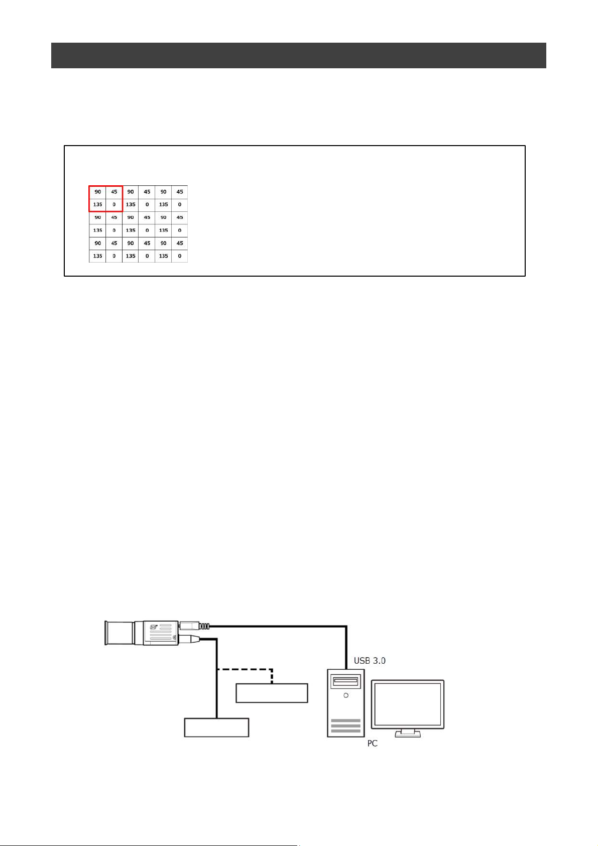
Image sensor with four-directional polarization
Polarizers are provided for individual pixels to capture polarization.
The numbers in the figure on the left indicate the
polarizer angles.
Four polarizer angles are available: 0º, 45º, 90º,
and 135º. Various polarization processing is
performed on the four pixels enclosed in the red
frame as a block.
Also, various functions considered necessary for machine vision are
provided.
The unit is equipped with pre-processing circuits for shading correction and
blemish correction in addition to external trigger, exposure setting, and
image level control.
Feature overview
• C
ompliance with USB3 Vision and GenICam standards
•2/3-inch global shutter and a four-directional polarization square pixel array that
offers 5.1 effective megapixels CMOS sensor
• L
ens mount: C-mount (flange back: 17.526 mm)
ixel size : 3.45 um × 3.45 um
• P
•Effective pixels 2464(H) × 2056(V)
p to 74 fps at full resolution
• U
• Various Video Output modes
Raw Image, Four polarizer, Four functions, Color on average image and
Color on gray image.
•Internal test signal for settings configuration
BUS SDK for JAI that supports Windows 7, 8, 10
• e
Connection example:
Camera
External Trigger
AC adapter
— 6 —
Page 7
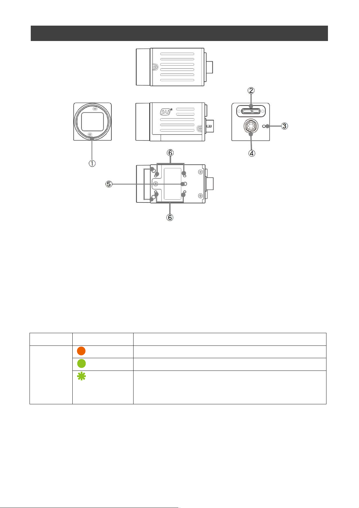
Parts Identification
GO-5100MP-USB
① Lens mount(C-mount)
Mount a C-mount lens, microscope adapter, etc. here.
❖ Before mounting a lens, be sure to refer to “Step 2:Connecting Devices” and confirm
the precautions for attaching a lens and the supported lens types.
② USB 3.0 connector
Use a USB 3.0 compatible cable to connect this to a USB port on the computer.
③ POWER/TRIG LED
Indicates the power and trigger input status.
LED status and camera status
LED Light Status
POWER/
TRIG LED
(Lit amber)
(Lit green)
(Blinking green)
Camera initializing.
Camera in operation.
During operation in trigger mode, trigger signals are
being input.
❖ The blinking interval is not related to the actual input interval of
the external trigger.
— 7 —
Page 8
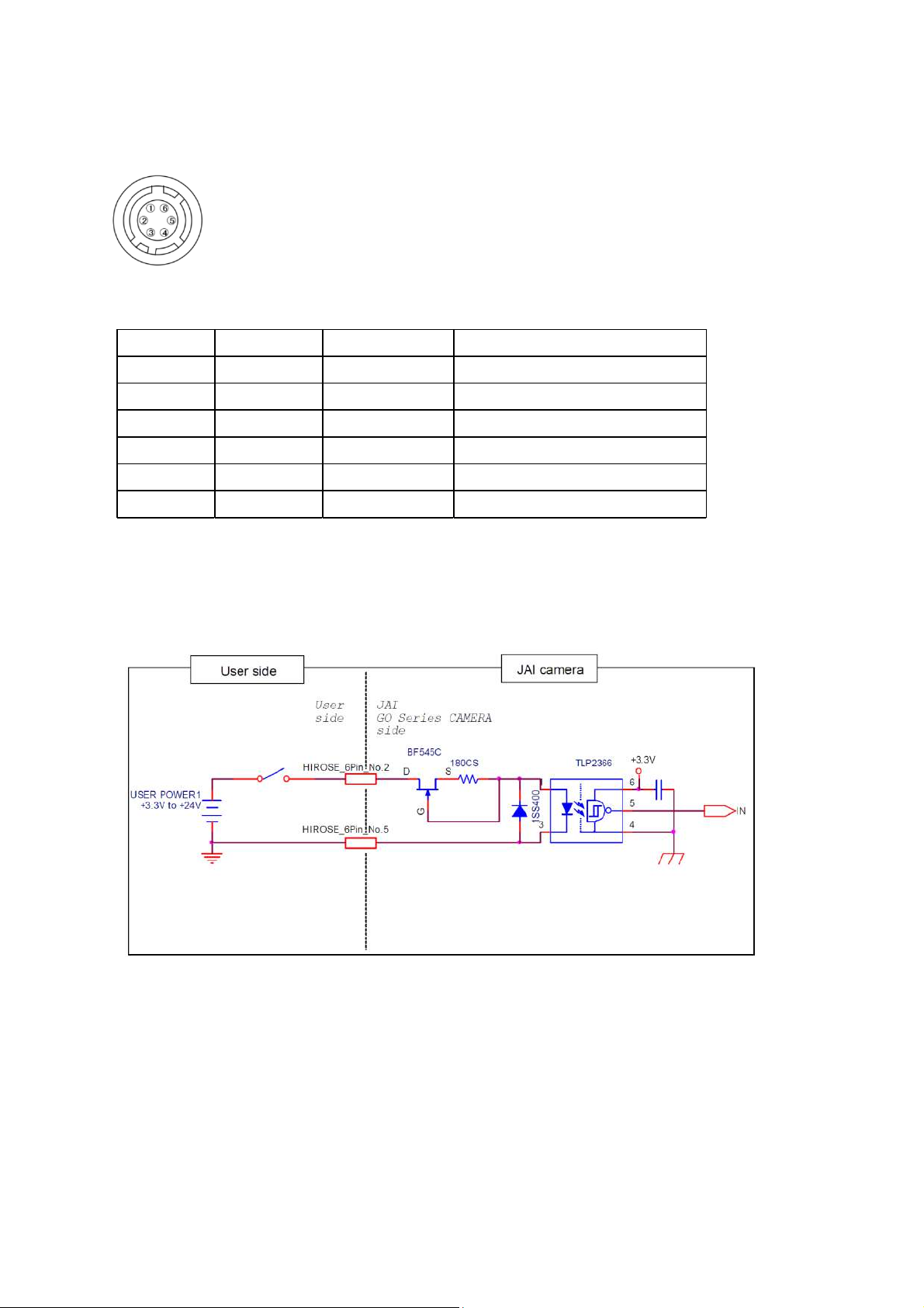
④ DC IN/TRIG connector(6-pin round)
Pin No.
Input/Output
Signal Description
1 Power In DC In DC 12 V ~ 24 V ± 10%
2 In Opto In 1 GPIO 5
3 Out Opto In 1 GPIO 1
4 Out Opto In 2 + GPIO 2
5 Opto Common
6 GND
Connect the cable for a power supply (optional) or for DC IN / trigger IN here.
HR10A-7R-6PB(73)(Hirose Electric or equivalent)
GO-5100MP-USB
Recommended external input circuit diagram (reference example)
— 8 —
Page 9

Recommended external output circuit diagram (reference example)
Standard circuit diagram example
GO-5100MP-USB
Characteristics of the recommended circuits for Opto OUT
— 9 —
Page 10

⑤ Camera locking screw holes(M3, 3mm depth)
Use these holes when attaching an MP-43 tripod adapter plate (optional) or
mounting the camera directly to a wall or other structural system.
⑥ Camera locking screw holes(M2, 3mm depth)
Use these holes when mounting the camera directly to a wall or other structural
system.
GO-5100MP-USB
— 10 —
Page 11
Preparation
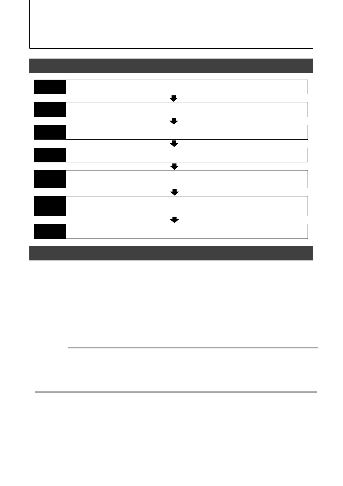
Preparation Process
GO-5100MP-USB
Step 1
Step 2
Step 3
Step 4
Step 5
Step 6
Step 7
Installing the Software (first time only)
Install the software for configuring and controlling the camera (eBUS SDK for JAI) on the computer.
Connecting Devices
Connect the lens, USB cable, AC adapter, computer, and other devices.
Verifying Camera Operation
Verify whether the camera is turned on and ready for use.
Verifying the Connection between the Camera and PC
Verify whether the camera is properly recognized via eBUS Player for JAI.
Changing the Camera Settings
Refer to the procedure for changing the output format setting as an example, and change various
settings as necessary.
Adjusting the Image Quality
Refer to the procedures for adjusting the gain, white balance, and black level as examples, and adjust
the image quality.
Saving the Settings
Save the current setting configurations in user memory.
Step 1: Installing the Software (first time only)
When using the camera for the first time, install the software for configuring and
controlling the camera (eBUS SDK for JAI) on the computer.
❖ When you install eBUS SDK for JAI, eBUS SDK for JAI player will also be installed.
Download the eBUS SDK for JAI from the JAI website.
1
URL https://www.jai.com/support-software/jai-software
Install eBUS SDK for JAI on the computer.
2
Caution
eBUS SDK for JAI was released in April 2018 and is the latest software for setting and
controlling JAI cameras.
When JAI SDK and eBUS SDK for JAI are installed on the same machine, conflicts can
occur. Therefore, JAI strongly recommends that JAI SDK is uninstalled before installing
eBUS SDK for JAI.
— 11 —
Page 12
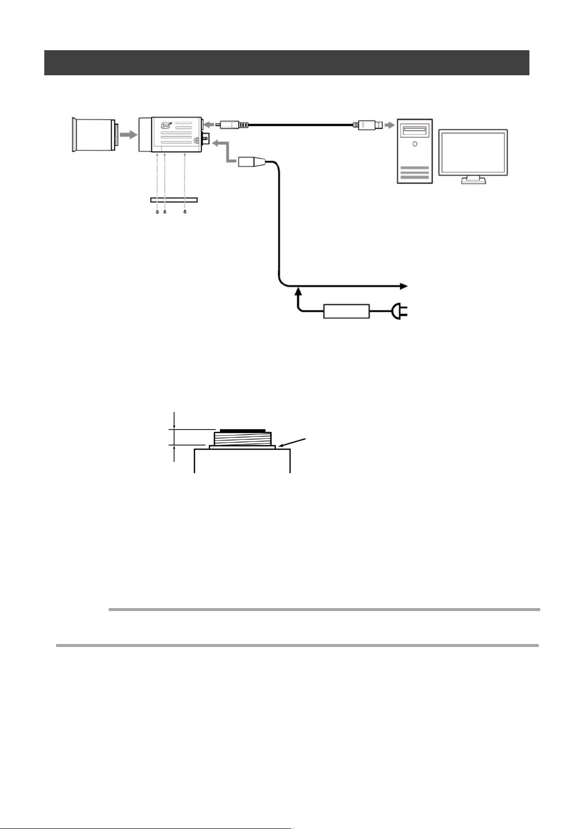
Step 2: Connecting Devices
GO-5100MP-USB
Camera body
① Lens
② Direct connection
(or MP-45 tripod
adapter plate)
③ USB cable
④ PC
⑤ DC IN / trigger IN
connection cable
to external trigger
or
⑥ AC adapter(not supplied)
(power supply)
① Lens
・C-mount lenses with lens mount protrusions of 9 mm or less can be attached.
9 mm or less
Lens
Lens mount protrusion
・The diagonal of the camera’s CMOS image sensor is 11 mm, the size of
standard 2/3-inch lenses.
To prevent vignetting and to obtain the optimal resolution, use a lens
that will cover the 11 mm diagonal. Some lens manufacturers offer lenses with
an 11 mm format. If not, a 2/3-inch lens is recommended.
Caution
・The maximum performance of the camera may not be realized depending on the lens.
・Attaching a lens with a mount protrusion of 9 mm or longer may damage the lens or camera.
— 12 —
Page 13

GO-5100MP-USB
Note
The following formula can be used to estimate the focal length.
Focal length = WD /(1 + W/w)
WD :Working distance (distance between lens and object)
W :Width of object
w :Width of sensor(8.5 mm on this camera)
② Direct connection(or MP-43 tripod adapter plate)
When mounting the camera directly to a wall or other device, use screws that match the
camera locking screw holes on the camera (M3, depth: 3 mm). Use the supplied screws to
attach the tripod adapter plate.
Caution
For heavy lenses, be sure to support the lens itself. Do not use configurations in which its weight
is supported by the camera.
③ USB cable
Connect a USB cable to the USB 3.0 connector.
Caution
The camera is equipped with a USB 3.0 compatible Micro B connector. Although this connector
includes USB 2.0 connectors, the camera does not support use of USB 2.0.
④ Computer
Use a computer that meets the following requirements.
Operating system (OS):
Microsoft Windows 7/8/10 32-bit/64-bit edition
CPU: Intel Core i3 or higher
Memory:
Windows 7/8/10 32-bit edition: DDR3, 4 GB or higher
Windows 7/8/10 64-bit edition: DDR3, 8 GB or higher
Graphics card: PCI-Express 3.0 or higher
Interface: USB 3.0 compatible connector
⑤ DC IN / trigger IN connection cable
⑥ AC adapter (power supply) (if necessary)
Connect the AC adapter and the round connector of the connection cable to the DC IN /
trigger IN connector on the camera.
— 13 —
Page 14

Step 3: Verifying Camera Operation
When power is supplied to the camera while the necessary equipment is connected, the
POWER/TRIG LED at the rear of the camera lights amber, and initialization of the camera
starts.When initialization is complete, the POWER/TRIG LED lights green.
Verify whether power is being supplied to the camera by checking the rear LED.
When properly turned on
Lit green
* For details on how to read the LEDs, see “LED status and camera status” in the “Parts
Identification” section.
GO-5100MP-USB
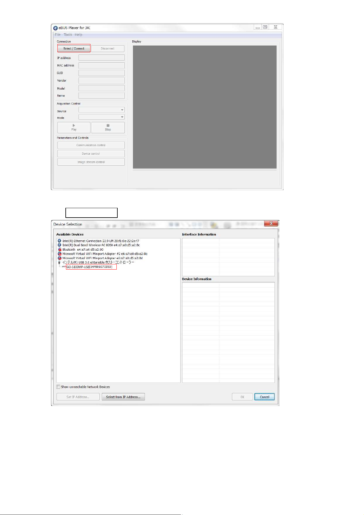
Step 4: Verifying the Connection between the Camera
and PC
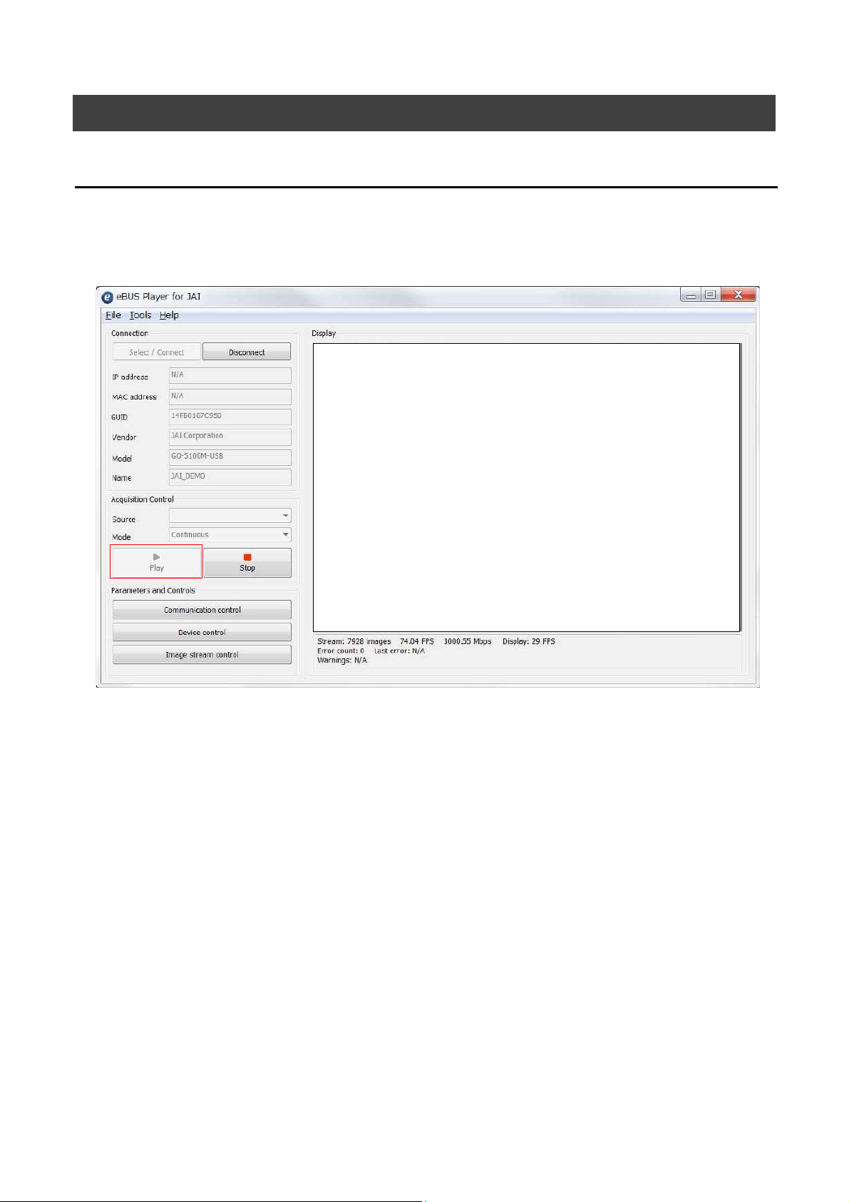
Verify whether the camera is properly recognized via eBUS Player for JAI.
Connecting the Camera to eBUS Player for JAI.
Startup eBUS Player for JAI
1
eBUS Player for JAI startup screen appears.
— 14 —
Page 15
GO-5100MP-USB
Select the camera you want to configure.
2
Push Select / Connect button
The connected camera is listed.
Please select one camera.
— 15 —
Page 16
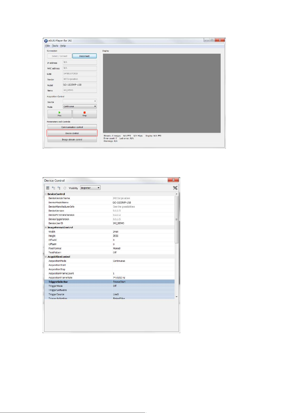
GO-5100MP-USB
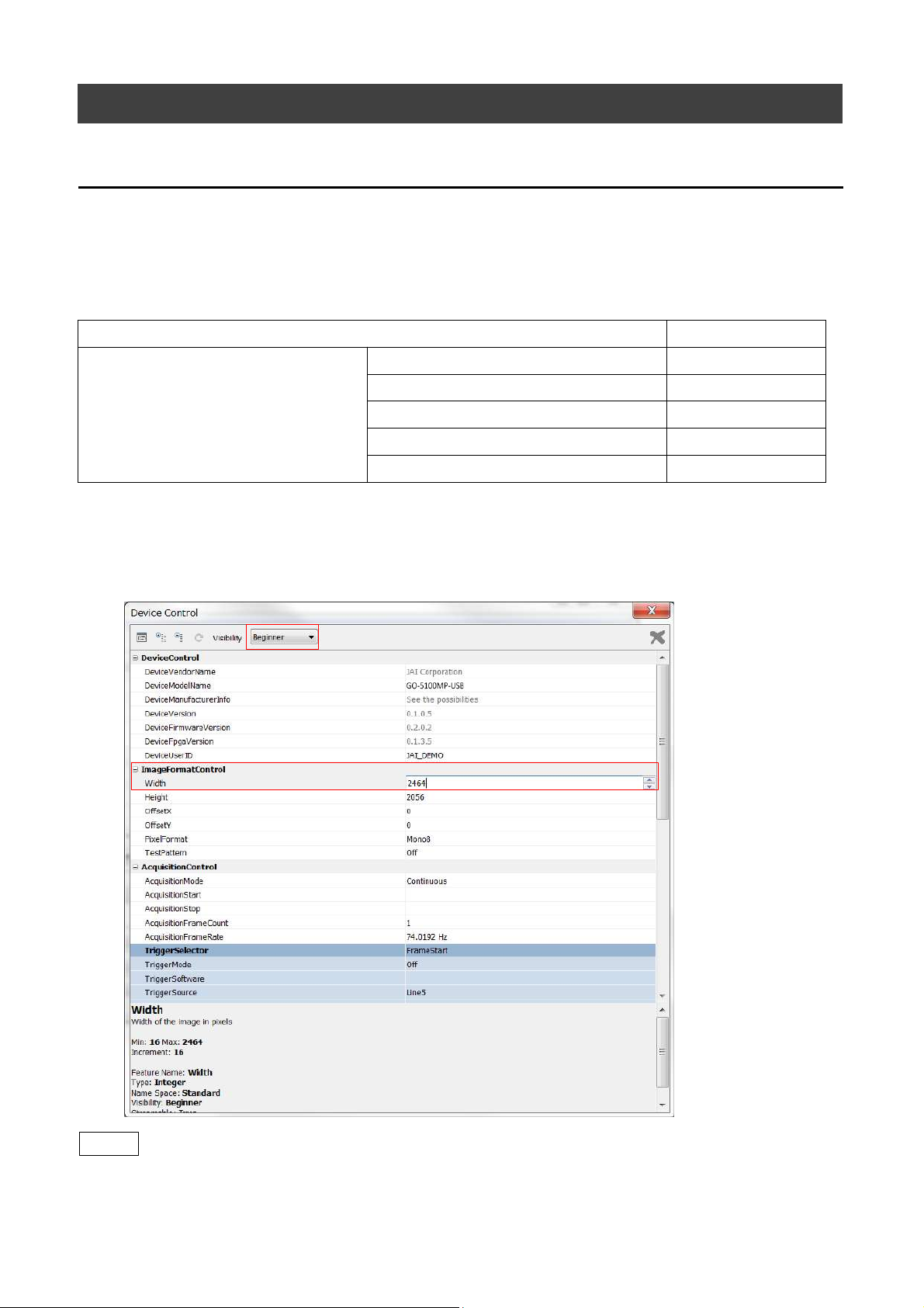
3
Check that the settings of the selected camera are displayed.
Push the Device control button.
The screen shown below will be displayed. In this window you can adjust various
settings of the camera.
This completes the procedure for verifying whether the camera is properly recognized and
whether control and settings configuration are possible.
— 16 —
Page 17
Step 5: Changing the Camera Settings
This section explains how to change settings by describing the procedure for changing the
output format as an example.
Configuring the Output Format
Configure the size, position, and pixel format of the images to be acquired.
The factory settings are as follows. Change the settings as necessary.
Factory default values
Item Default value
ImageFormatControl
Width 2464
Height 2056
OffsetX (horizontal position) 0
OffsetY (vertical position) 0
PixelFormat Mono8
GO-5100MP-USB
* You can specify the image acquisition area. For details, see “ROI (Regional Scanning Function)”.
Configuring the [Width] of[ImageFormatControl]
1
By selecting the item of [Width], you can change the value as shown below.
Note
Depending on the setting item, you need to change visibility.
Please switch visibility (Beginner / Expert / Guru) as necessary.
— 17 —
Page 18
Step 6: Adjusting the Image Quality
Display the camera image and adjust the image quality.
Displaying the Image
Display the image captured by the camera.
When you push [Play] button, the camera image appears in right area.
GO-5100MP-USB
— 18 —
Page 19

Adjusting the Gain
Adjust the image quality using the gain function.
To adjust the image quality
The Visibility must be changed from [Beginner] to [Guru].
Adjust the sensitivity via the analog gain (i.e., master gain).
For details on gain control, see “Gain Control” in the “Main Functions” section.
■ Manual adjustment
Expand [AnalogControl], and set [GainAuto] to [Off].
1
([Off] is default setting.)
Configure the gain.
2
❶ Expand [AnalogControl], and select the gain you want to configure in [GainSelector].
[AnalogAll] (master gain) can be configured.
GO-5100MP-USB
❷ Configure the gain value in [Gain].
• [AnalogAll] (master gain) can be set to a value from x1 to x16 the analog gain
value. The resolution is set in x0.1 steps. Values are configured by multipliers.
Adjusting the Black Level
Expand [AnalogControl], and select the black level you want to configure in
1
[BlackLevelSelector].
[DigitalAll] (master black) can be configured.
Specify the adjustment value in [BlackLevel].
2
— 19 —
Page 20
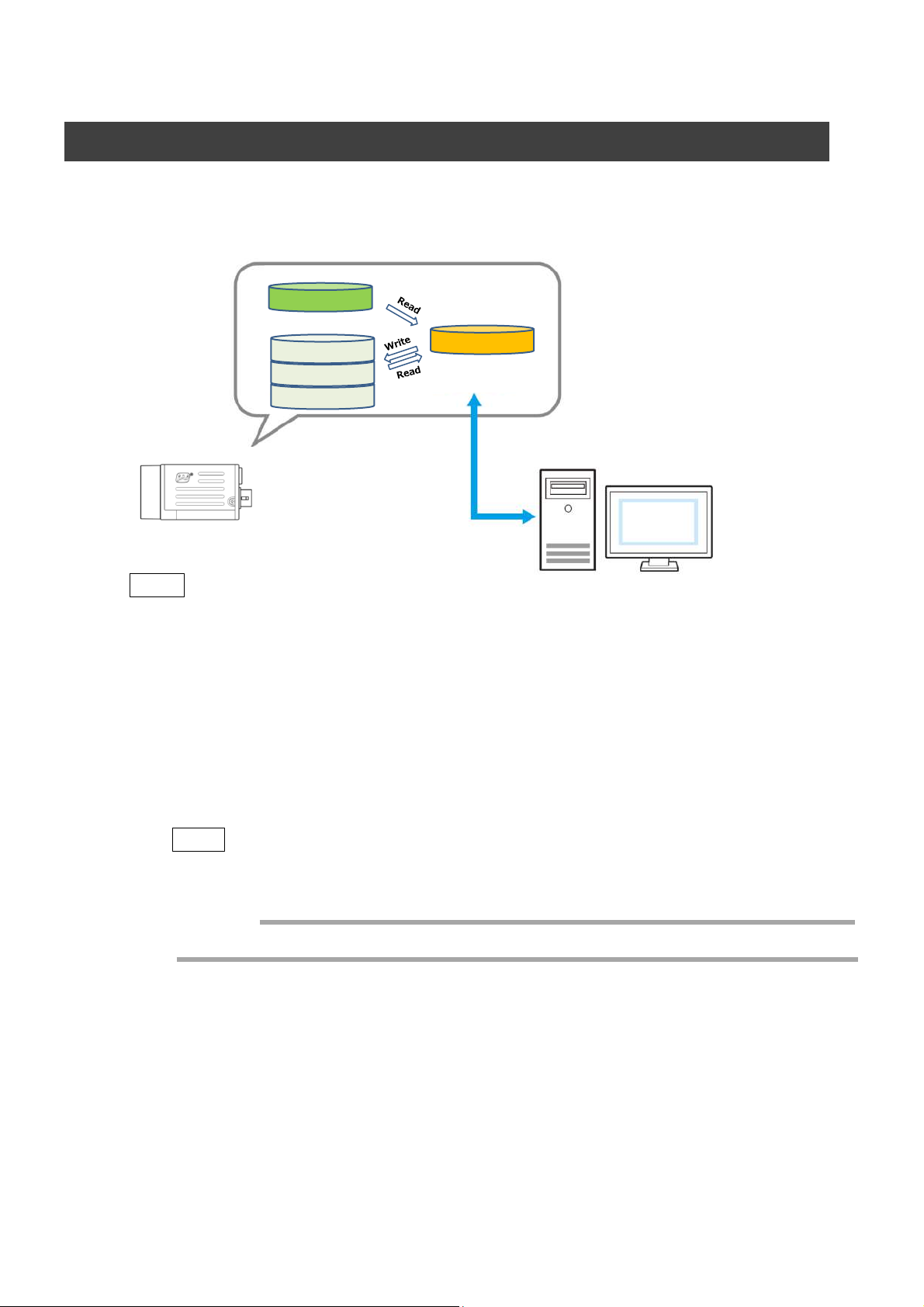
Step 7: Saving the Settings
The setting values configured in the player (eBUS SDK for JAI) will be deleted when the
camera is turned off. By saving current setting values to user memory, you can load and
recall them whenever necessary. You can save up to three sets of user settings in the
camera. (User Set1 to 3)
GO-5100MP-USB
Memory(Flash)
DefaultSet
UserSet1
UserSet2
UserSet3
Note
Changes to settings are not saved to the computer (eBUS SDK for JAI).
■ To save user settings
Stop image acquisition.
一時メモリ
Memory(RAM)
Working Set
1
eBUS SDK for
JAI (Player)
Expand [UserSetControl], and select the save destination ([UserSet1] to
2
[UserSet3]) in [UserSetSelector].
Note
The factory default setting values are stored in [Default] and cannot be overwritten.
Caution
Settings can only be saved when image acquisition on the camera is stopped.
Select [UserSetSave], and click [Execute ‘UserSetSave’ Command].
3
The current setting values are saved as user settings.
— 20 —
Page 21

■ To load user settings
Stop image acquisition.
1
User settings can only be loaded when image capture on the camera is stopped.
Select the settings to load (UserSet1 to UserSet3) in [UserSetSelector].
2
Select [UserSetLoad], and click [Execute ‘UserSetLoad’ Command].
3
The selected user settings are loaded.
GO-5100MP-USB
— 21 —
Page 22

Main Functions
TriggerSequencerMode
CommandSequencerMode
Off Off × ○ ○ × ×
Timed Off ○ ○ ○ × ○
Timed(EPS) On ○ ○ ○ ○ ○
TriggerWidth On × ○ ○ × ×
ROI
GainAuto
Sequencer
ExposureMode
FrameStartTrigger
ExposureTime
Basic Function Matrix
The combinations of settings for the basic functions that can be used together are as follows.
GO-5100MP-USB
GPIO (Digital Input/Output Settings)
The camera is equipped with GPIO (general-purpose input/output) functions for generating
and using combinations of triggers and other necessary signals within the camera and of
signals output from the camera to the system such as those used for lighting equipment
control.
Valid Input/Output Combinations
The following signals can be used as sources for each output destination (Trigger Selector,
Line Selector, Pulse Generator Selector).
You can also connect two different sources to NAND paths in the GPIO and reuse the signal
generated there as a source for a different selector.
— 22 —
Page 23

The combinations of source signals and output destinations are indicated in the following.
PixelFormat
Mono8, Mono10, Mono10packed
*1) Mono12, Mono12Packed
*2) BayerRG8, BayerRG10, BayerRG10Packed
GO-5100MP-USB
: Indicates default values for each selector.
Camera Output Formats
The GO-5100MP-USB supports the following output formats.
*1) When VideoProcessBypassMode is enabled, PixelFormat can be set to Mono12 or Mono12Packed.
In this case, the image output mode of the camera will be fixed to the RawImage mode.
For details, see "12-bit Output" section.
*2) PixelFormat is switched to BayerRG8, BayerRG10, or BayerRG10Packed automatically depending
on the output mode setting (PolarizeImageSelector) of the camera. For details, see the "Camera
Image Output Modes" section.
— 23 —
Page 24

GO-5100MP-USB
Camera Image Output Modes
The GO-5100MP-USB has five output modes.
First, we will explain about the monochrome CMOS image sensor with a four-directional polarization
square pixel array that is incorporated in this camera.
A polarizer with one of the four angles of 0º, 45º, 90º, and 135º is provided for each pixel.
The numbers in the figure on the left indicate the
polarizer angles.
Four polarizer angles are available: 0º, 45º, 90º,
and 135º. Various polarization processing is
performed on the four pixels enclosed in the red
frame as a block.
The number of effective pixels is 2464 x 2056, and polarizers angled at 90º and 45º are
provided alternately for each pixel on the first line. Polarizers angled at 135º and 0º are
provided alternately for each pixel on the second line.
2464 pixels
2056 pixels
1. RawImage mode
The data output from the image sensor is output as is from the camera.
As shown in the figure above, the data of the pixels where there are polarizers angled at
90º and 45º is output as the first line, and the data of the pixels where there are
polarizers angled at 135º and 0º is output as the second line.
— 24 —
Page 25

2. FourPolarizeElement mode
The data is output arranged as a screen divided into four (pixels of the polarizers angled
at 45º at the top right, pixels of the polarizers angled at 90º at the top left, pixels of the
polarizers angled at 0º at the bottom right, and pixels of the polarizers angled at 135º at
the bottom left).
1232 pixels
1028 pixels
GO-5100MP-USB
3. FourFunctions mode
This mode allows you to set each quadrant of the screen to one of five available
functions. The five selectable functions are:
PolarizeAngle (polarization angle), PolarizeRatio (polarization ratio),
DiffusedLight (diffused light), PolarizedLight (polarized light),
and AverageLight (average brightness)
The follow example shows the settings that would be used to configure the output
into four functions arranged as shown in the screen diagram below.
PolarizeAngle
DiffusedLight
PolarizeRatio
PolarizedLight
Setting item Setting value
PolarizeImageSelector: FourFunctions
Panel1selector: PolarizeAngle
Panel2selector: PolarizeRatio
Panel3selector: DiffusedLight
Panel4selector: AverageLight
— 25 —
Page 26

GO-5100MP-USB
*) The same function can be output in multiple quadrants.
Polarization angle:
The polarization angle producing the greatest luminance for a given pixel block.
Intensity values assigned to pixels represent angles from 0 to 180˚.
8-bit output: 00000000 to 10110100
10-bit output: 0000000000 to 1110000100
Polarization ratio:
The proportion of polarized light (at the angle described above) contained within
the total light falling on a pixel block. Intensity values represent proportions of
polarized light from 0 to 100%.
8-bit output: 00000000 to 11111111
10-bit output: 0000000000 to 1111111111
Diffused light:
The intensity of light falling on a pixel block when some or all of the polarized
light is excluded. The ReflectionAdjust control determines how much of the
polarized component is removed. The higher the ReflectionAdjust setting, the
more polarized light is removed. Set to maximum to display only the diffused
component.
Polarized light:
The intensity of the polarized light that is falling on a pixel block after the diffused
light has been excluded.
Average light:
The brightness of a pixel block when the polarized component and the diffused
component are averaged.
Two additional output modes are available to users. These are not selectable in the
FourFunctions mode. Instead, they produce a single image that combines
information from the functions above with the main image being captured.
4. ColorOnPicture mode
This mode provides a pseudo-color overlay representing polarization angle and
polarization ratio information displayed over an image built using average light
information. The PixelFormat is automatically changed in this mode as follows:
When PixelFormat is Mono8, the image is output as BayerRG8
When PixelFormat is Mono10, the image is output as BayerRG10
When PixelFormat is Mono10Packed, the image is output as BayerRG10Packed
5. ColorOnGray mode
This mode provides a pseudo-color overlay representing polarization angle and
polarization ratio information displayed over a gray image. The PixelFormat is
automatically changed in this mode as follows:
When PixelFormat is Mono8, the image is output as BayerRG8
When PixelFormat is Mono10, the image is output as BayerRG10
When PixelFormat is Mono10Packed, the image is output as BayerRG10Packed
— 26 —
Page 27

GO-5100MP-USB
Binning Function
The binning function allows you to combine the signal values of clusters of adjacent pixels to
create improved virtual pixels. Using the function results in images with lower pixel resolution
and higher sensitivity.
This camera performs both horizontal binning and vertical binning via digital addition or
averaging processing.
The following four conditions must be met to use the binning function.
1. [PolarizeImageSelector] is [RawImage].
2. The ROI function, sequencer function, and binning function cannot be used at the
same time.
3. PixelFormat is one of Mono8, Mono10, and Mono10p.
4. [VideoProcessBypassMode] is [Off].
■ When horizontal binning only (2x1)
The signal values of the pixels having polarizers at the same angle are combined. The signal
values of the two pixels indicated by the red frames in the following figure are combined.
The image data output from this camera becomes RawImage with 1232 pixels
(horizontally) x 2056 pixels (vertically).
1232 pixels
2056 pixels
■ When vertical binning only (1x2)
The signal values of the pixels having polarizers at the same angle are combined.
The signal values of the two pixels indicated by the red frames in the following figure
are combined.
— 27 —
Page 28

GO-5100MP-USB
The image data output from this camera becomes RawImage with 2464 pixels
(horizontally) x 1028 pixels (vertically).
2464 pixels
1028 pixels
■ When horizontal and vertical binning (2x2)
The signal values of the pixels having polarizers at the same angle are combined.
The signal values of the four pixels indicated by the red frames in the following figure
are combined.
The image data output from this camera becomes RawImage with 1232 pixels
(horizontally) x 1028 pixels (vertically).
1232 pixels
1028 pixels
— 28 —
Page 29

12-bit Output
With this camera, when VideoProcessBypassMode is enabled, output with PixelFormat
as Mono12 or Mono12Packed is possible.
When VideoProcessBypassMode is enabled, video output is fixed to the RawImage
mode and the binning function and ROI function cannot be used.
ROI (Regional Scanning Function)
The ROI (region of interest) function allows you to output images by specifying the areas to
scan.
ROI Settings
Specify the area to scan by specifying width, height, and horizontal/vertical offset values
under [ImageFormatControl].
GO-5100MP-USB
Scanning range
2056 Height Max
2464 Width Max
You can increase the frame rate by specifying a lower height, as the number of lines
scanned decreases.The setting ranges for the ROI function's readable area based on the
Binning setting (BinningHorizontal, BinningVertical) are as follows.
— 29 —
Page 30

Image Acquisition Controls
AcquisitionMode Description
SingleFrame
Acquire a single frame when the [AcquisitionStart]
command is executed.
MultiFrame
Acquire the number of frames specified in
[AcquisitionFrameCount] when the [AcquisitionStart]
command is executed.
Continuous
Acquire images continuously until the
[AcquisitionStop] command is executed.
Perform operations and configure settings related to image acquisition in [AcquisitionControl].
The following acquisition modes are available on the camera.
GO-5100MP-USB
Changing the Frame Rate
When [TriggerMode] is disabled, you can change the frame rate in [AcquisitionFrameRate].
Note
• The shortest frame period varies depending on the ROI, pixel format, and binning mode
selected. The longest frame period is 0.125 Hz (8 sec.).
• When TriggerMode[FrameStart] is enabled, the [AcquisitionFrameRate] setting is disabled.
Maximum Frame Rate
The maximum frame rate is the smaller value between the SensorFR that is calculated from
the readable range of the sensor and the InterfaceFR that is limited by the USB 3.0 bandwidth.
Maximum frame rate
(Value derived from sensor
scanning range)
SensorFR
Compared
Maximum frame rate
(Value derived from USB 3.0
bandwidth)
InterfaceFR
SensorFR < InterfaceFR
Maximum frame
SensorFR
— 30 —
SensorFR > InterfaceFR
Maximum frame
InterfaceFR
Page 31

GO-5100MP-USB
■ Maximum frame rate period formula
During continuous operation ([Frame Start] trigger is [Off] or [Exposure Mode] is [Off])
• Maximum frame rate of sensor output
SensorFR = 1 / {Hperiod × (Height + 40)}
• Maximum frame rate by interface
InterfaceFR = 3000 × 1000000 / (Height × Width × Pack value)
• Maximum frame rate
FR_Cont = Min (Sensor FR, Interface FR)
When the exposure time is longer than the frame interval
• Maximum exposure time at maximum frame rate
MaxExposureTime_TrOlrd = (1 / FR_Cont) - (14 × H Period)
• Exposure time outside of frame interval
NonOverlapExposureTime = ExposureTime - MaxExposureTime_TrOlrd
However, NonOverlapExposureTime calculation results that are 0 or below will be considered as 0.
• Maximum frame rate
FR_ContLongExposure = 1/{(1/FR_Cont) + NonOverlapExposureTime}
When [Frame Start] trigger is [On] and [Trigger OverLap] is [Off]
• Maximum frame rate of sensor output
Sensor FR = 1 / {H Period × (Height + 40)}
• Maximum frame rate by interface
Interface FR = 3000 × 1000000 / (Height × Width × Pack value)
• Maximum frame rate
FR_Cont = Min (Sensor FR, Interface FR)
• Exposure time possible within frames
MaxOverlapTime_TrOloff = (1 / FR_Cont) - (1 / Sensor FR)
• Exposure time outside of frame interval
NonOverlapExposureTime_TrOloff = ExposureTime - MaxOverlapTime_TrOloff
For TriggerWidth, the trigger pulse is equivalent to ExposureTime.
However, NonOverlapExposureTime_TrOloff calculation results that are 0 or below will be considered as 0.
• Maximum frame rate
FR_TrOloff = 1 / {(1 / FR_Cont) + NonOverlapExposureTime_TrOloff}
When [Frame Start] trigger is [On] and [Trigger OverLap] is [Readout]
• Maximum frame rate of sensor
Sensor FR = 1 / {H Period × (Height + 40)}
• Maximum frame rate by interface
Interface FR = 3000 × 1000000 / (Height × Width × Pack value)
• Maximum frame rate
FR_Cont = Min (Sensor FR, Interface FR)
• Exposure time possible within frames
MaxOverlapTime_TrOlrd = (1 / FR_Cont) - (14 × H Period)
• Exposure time outside of frame interval
NonOverlapExposureTime_TrOlrd = ExposureTime - MaxOverlapTime_TrOlrd
However, NonOverlapExposureTime_TrOlrd calculation results that are 0 or below will be considered as 0.
For TriggerWidth, the trigger pulse is equivalent to ExposureTime.
• Maximum frame rate
FR_TrOlrd = 1 / {(1 / FR_Cont) + NonOverlapExposureTime_TrOlrd}
— 31 —
Page 32

ExposureMode
ExposureMode Description
Off Exposure control is not performed (free-running operation).
Timed
Mode in which control is performed using exposure time. Acquire
images using an exposure time configured beforehand on an external
trigger.
TriggerWidth
Mode in which control of the exposure time is performed using the
pulse width of the trigger input signal. The exposure time will be the
same as the pulse width of the trigger input signal. This allows long
exposure.
Exposure Mode Shortest exposure time
Timed
14.7μs
TriggerWidth
14.7μs
The following exposure modes are available on the camera.
GO-5100MP-USB
* T h e settings for exposure control and triggers are related to each other. Be sure to configure the
settings described in “Trigger Control”.
Actual Exposure Times
The shortest exposure times that can be configured are as follows.
・The actual exposure time will consist of the image sensor’s offset duration (13.7 μs) added
to the setting configured on the camera.
・When [ExposureMode] is set to [Timed] and the exposure time is set to 1 μs, the actual
exposure time will be as follows.
1 μs + 13.7 μs (offset duration of image sensor) = 14.7 μs
・When [ExposureMode] is set to [TriggerWidth], the exposure is slightly longer than the width
of the trigger signal. To achieve an exposure time of 14.7 µs and the exposure time offset
is 13.7 µs, use 14.7 µs - 13.7 µs = 1 µs as the high or low time for the trigger signal.
— 32 —
Page 33

Trigger Control
TriggerSelector Description
FrameStart
Start exposure in response to the external trigger signal input. Select
this to perform exposure control using external triggers.
AcquisitionStart Start image acquisition in response to the external trigger signal input.
AcquisitionEnd Stop image acquisition in response to the external trigger signal input.
AcquisitionTransferStart
Output acquired images at a specified timing in response to an
external trigger signal input.
* There is a limit to the number of image frames that can be stored
internally. The limits for each image format are as follows. Acquired
images must be output to avoid exceeding these limits.
8 bit: Up to 8 frames
10 bit: Up to 4 frames
12 bit: Up to 4 frames
The camera allows the following controls to be performed via external trigger signals.
GO-5100MP-USB
• The settings for exposure control and triggers are related to each other. Be sure to
configure the settings described in “ExposureMode” .
Shortest Repetition Period for Triggers
The reciprocal of the maximum frame rate is the time required to output one frame. The
shortest repetition periods for triggers cannot be lower than that value.
The above table indicates the shortest trigger periods for when [TriggerOverLap] is set to
[Readout]. When [TriggerOverLap] is set to [Off], even when the exposure time is shorter
than the frame period, the cycle may be extended.
— 33 —
Page 34

GO-5100MP-USB
PixelFormat Sensor Dig Bit
Period from Trigger
start edge to
Exposure start [A]
(usec)
Period from Exposure
end to FVAL start [B]
(usec)
Period FVAL end to
next trigger start [C]
(usec)
Mono8
12 25.1 201.8 1.9
Mono10Packed
12 28.3 238 6.7
Mono10
12 28.3 237 6.1
■ When [ExposureMode] is [Timed]
Example: When [TriggerSource] is set to [Line 5 - OptIn1] and [OptInFilterSelector] is set
to [10 µs]
• TriggerOverlap:Off
— 34 —
Page 35

• TriggerOverlap:readout
GO-5100MP-USB
— 35 —
Page 36

GO-5100MP-USB
■ When [ExposureMode] is [TriggerWidth]
Example: When [TriggerSource] is set to [Line 5 - Optical In 1] and [OptInFilterSelector]
is set to [10 µs]
• TriggerOverlap:Off
— 36 —
Page 37

• TriggerOverlap:readout
GO-5100MP-USB
— 37 —
Page 38

Gain Control
Adjust the [AnalogAll] (master gain) setting.
Analog All
GO-5100MP-USB
x 16
x 1.0
24dB
0dB
LineStatus
The line status function allows you to verify the status of external input/output signals. You
can verify the status of the following signals.
• Line5-OptIn1, Line6-OptIn2
• NANDGate0In1, NANDGate0In2
• NANDGate1In1, NANDGate1In2
• Line1-TTLOut1, Line2-OptOut1
• TimestampReset
— 38 —
Page 39

BlemishCompensation
Multiple defective pixels that are not adjacent to each other can occur on conventional CMOS
sensor cameras.
This camera features a function that interpolates defective pixels using the surrounding pixels.
Up to 256 pixels can be corrected for each of the three sensors. Pixel interpolation can be
performed via automatic detection or point-by-point manual settings.
■ Automatic detection
Automatic detection can only detect lit defective pixels (i.e., white blemishes).
Shield the camera sensor.
1
If a lens is attached, use the lens cap as a shield, for example.
Configure the threshold level for defective pixel detection.
2
Up to 256 pixels can be corrected.
The threshold value is specified as a percentage.
The default setting is "10" with 10% of the full scale (100%) specified as the threshold
value.
GO-5100MP-USB
Execute [BlemishDetect] to start automatic detection.
3
After detection, the interpolation data is saved to the camera's internal memory.
To check the number of interpolated pixels after automatic detection
You can check the number of pixels interpolated via automatic detection by loading the
BlemishNum data.
■ Manual configuration
Select the index in [BlemishCompensationIndex].
1
You can select from 0 to 255. However, configure the indexes in order starting
with the smallest index. If you skip indexes while configuring settings,
interpolation may not be performed.
Specify the pixel points for interpolation using the
2
[BlemishCompensationPositionX] and [BlemishCompensationPositionY] settings.
You can configure values that are within the total effective pixel area. Specify pixels for
which interpolation is not necessary as -1. If 0 is specified, the first line or first pixel
will be interpolated.
Note
BlemishCompensationDataClear[BlemishCompensationIndex], you can return a specific pixel
correction setting to the default value (storage not required).
Execute [BlemishStore].
3
Blemish compensation data will be stored.
Set [BlemishEnable] to [True], and execute interpolation.
4
If it is set to [False] , Blemish compensation is not effective.
— 39 —
Page 40

ShadingCorrection
The shading correction is a function that corrects non-uniformity (i.e., shading) in the amount
of light generated by the lens and lighting equipment. Using this function allows correction
even if top, bottom, left, and right shading is not symmetrical in relation to the center of the
screen (H, V).
The size of the correction block is 20 (H) × 17 (V) blocks and calculation errors in the
correction data are minimized due to the small interpolation block. Each block is 128 × 128
pixels.The total size of the blocks is 2560 (H) × 2176 (V), but the actual number of effective
pixels for the camera is 2464 (H) × 2056 (V). The ineffective peripheral areas will be deleted
internally on the camera automatically.
GO-5100MP-USB
The following shading correction modes are available on the camera.
■ FlatShading
Correction is performed using the area of the screen with the highest brightness level as the
reference, and adjusting the brightness levels of the other areas to match this level.
Pre-correction
Post-correction
Caution
Proper correction is not possible under the following conditions.
• If an area with a brightness level that is more than 30% less than the reference level exists
within the screen
• If the brightness level is saturated in parts or all of the screen
• If the area in the screen with the highest brightness level is 300 LSB or less
(during 10-bit video output)
— 40 —
Page 41

■ To use the shading correction function
Item Setting value Description
ShadingCorrectionMode
FlatShadin g Select the shading correction mode.
ShadingMode User1, User2, User3 , Off
Select the user area to which to save the
shading correction value.
Configure the settings as follows.
Display a white chart under a uniform light, and execute [PerformShadingCalibration].
Note
After shading correction is executed, the shading correction value is automatically saved to the
user area selected in [ShadingMode].
GO-5100MP-USB
— 41 —
Page 42

Sequencer Function
The Sequencer function lets you define up to 128 index combinations of exposure time, gain,
ROI, and other settings which can be stepped through each time a trigger is received.This is
particularly useful for quickly capturing multiple exposures of objects under inspection to adjust
for areas or components with significantly different levels of reflectance. You can specify the
next index in the stepping sequence and the order in which indexes are executed. Multiple
indexes can also be executed repeatedly.
Two operation modes (TriggerSequencer mode and CommandSequencer mode) are available
for the Sequencer function.
Note
The following four conditions must be met to use the Sequencer function.
1. [PolarizeImageSelector] is [RawImage].
2. Sequencer Width, Sequencer Offset X function, and Sequencer H Binning function
cannot be used at the same time.
3. Sequencer Height, Sequencer Offset Y function, and Sequencer V Binning function
cannot be used at the same time.
GO-5100MP-USB
About indexes (imaging conditions)
Up to 128 indexes can be configured.The following settings can be configured for each
index. However, SequencerFrameNumber and SequencerSetNext can only be configured
in TriggerSequencer mode.
Trigger Sequencer mode
With this mode, the Sequencer Trigger “pattern” is predetermined by the user. The user
defines up to 128 different “indexes.” The items indicated in the above index can be
configured for each index. The operation of this mode is controlled using the following five
commands.
[SequencerSetActive]
This allows you to confirm the currently configured index number.
[SequencerSetStart]
This configures the index number to execute at the start of TriggerSequencer mode.
[SequencerReset]
During TriggerSequencer mode operation, this switches the index number to be executed to
that specified in [SequencerSetStart].
[SequencerRepetition]
This parameter applies to TriggerSequencer patterns which include an index whose
[SequencerROINextIndex] is set to 0 (OFF).When the index whose [SequencerROINextIndex]
is set to 0 (OFF) is finished executing, the value of Sequencer Repetition (range = 1-255) is
decremented internally. If the result of the decrement is not zero, the TriggerSequencer
pattern starts over from the index specified in SequencerSetStart. If the result of the
decrement is zero, the status changes to Acquisition Stop and external triggers are not
accepted.
— 42 —
Page 43

Sample TriggerSequencer mode operation
User-defined Indexes (up to 128)
Triggers/
Image
Frames
Specify "1" in [SequencerSetStart], and start TriggerSequencer mode with index 1.
1
Capture a 2-frame image with the first and second triggers.
2
GO-5100MP-USB
For the next index, configure index 3 specified in [SequencerSetNext], and capture
3
an image with the number of frames (number of triggers) specified in
[SequencerFrameNumber].
Proceed to sequence from index 4 to index 2 to index 1.
Note
In addition to repeating multiple conditions as in the above example, you can specify "0"
(which indicates the end of TriggerSequencer mode) in [SequencerSetNext] of index 2, and
specify the number of repetitions in [SequencerRepetition].
Command Sequencer mode
As with TriggerSequencer mode, you can define up to 128 indexes beforehand in this mode. Set
[SequencerCommandIndex] to point to one of your pre-configured indexes. This index will be
executed on each trigger, until it is changed to point to a different index, typically by your vision
application. In this way, Command Sequencer mode allows you to programmatically adjust your
sequence in response to image analysis or input from other sensors.
Note
• The same index table will be executed for subsequent triggers unless the
[CommandSequencerIndex] value is changed.
• [SequencerFrameNumber] and [SequencerSetNext] cannot be used in CommandSequencer
mode.
Command
Sequencer
Index
2
Index
Selector
(MUX)
Index1
Index2
Index3
ROI1 Exposure1 Gain1 Binning1
ROI2 Exposure2 Gain2 Binning2
・
・
・
ROI128 Expo sure128 Gain128 Binning128
— 43 —
Page 44

Delayed Readout
Delayed readout allows images captured by a [FrameStart] trigger command to be stored
temporarily inside the camera (delayed readout buffer) and read out using a
[AcquisitionTransferStart] trigger after capture.This function is useful when executing triggers
simultaneously on multiple cameras.
Note
This function imposes a heavy processing load on the network bandwidth, as images from
multiple cameras are read out simultaneously. The number of frames that can be stored for
delayed readout depends on PixelFormat.
For details, see “Trigger Control” .
CounterAndTimerControl Function
The counter function counts up change points in the camera’s internal signals using the
camera’s internal counter, and reads that information from the host side. This function is
useful for verifying error conditions via the count value using internal camera
operations.Counting is performed at frame trigger, frame start, exposure start, and exposure
transfer end, and by comparing these values, you can determine the internal camera state at
which missed triggers will occur.
GO-5100MP-USB
■ Counter occurrence diagram
FrameStartTrigger
Counter0
ExposureStart
Counter1
Note
Event occurrence
Count up
Event occurrence
Count up
Counter1
Request
Counter0
Request
Read count
value
MCU
HOST
Read out
value
Counter reset
Count 0 reset
Counter reset
Counter1 reset
You can reset a specific counter's count value by executing CounterReset[Counter0, Counter1,
Counter2, Counter3].
— 44 —
Page 45

■ Internal camera blocks
Setting value /
selectable range
Description
Counter 0 to 2 Select the counter.
Counter 0 to 2 Event Source
Off,
Frame Trigger, Frame Start,
Exposure Start, Exposure
Transfer End
Select the counter event signal
for which to read the count
value.
Counter 0 to 2 Event Activation
Rising Edge or Falling Edge
Specify the timing at which to
count.
Item
Counter 0 to 2
■ To use the counter function
Configure the settings as follows.
Three counters can be configured (Counter 0 to 2).
GO-5100MP-USB
* The three counter event signals are always counted up internally on the camera.
— 45 —
Page 46

Chunk Data Function
The Chunk Data function adds camera configuration information to the image data that is
output from the camera. Embedding camera configuration information in the image data
allows you to use the serial number of the camera as a search key and find specific image data
from among large volumes of image data. In addition, when images are shot with a single
camera in sequence under multiple setting conditions, you can search for images by their
setting conditions.
The following information can be added to image data as chunk data.
■ Configuring Chunk Data
Set [ChunkModeActive] to [True].
1
Select the items of information you want added to image data with
2
[ChunkSelector], and set [ChunkEnable] from [False] to [True].
Note
When [ChunkModeActive] is set to [True], [ChunkImage] is automatically set to [True].
GO-5100MP-USB
Caution
The Chunk Data function settings cannot be changed during image output. To change the
settings, stop Acquisition.
*) For items that can be added to image data as Chunk Data, refer to [m) ChunkDataControl]
in the setting item list.
Video Process Bypass Mode
The video process bypass mode is a function that bypasses internal video processing on the
camera. When bypass is enabled, the sensor output and camera output data can be set to the
same bit width. Operation using 12-bit outputs must be performed in bypass mode.
Functions disabled in Video Process Bypass mode
BlackLevel, Shading, Binning(H, V)
Polarize Image Selector (Fixed to Raw Image)
PixelFormat available only in Video Process Bypass mode
Mono12, Mono12Packed
— 46 —
Page 47

Setting List
Feature Properties
GO-5100MP-USB
Item
a) Device Control
Device Vendor Name
Device Model Name
Device Manufacturer Info
Device Version
Device Firmware Version
Device Serial Number
Device User ID
Device Temperature Selector
Device Temperature(C) ー ー Display the internal temperature (°C) of
Device Reset
Setting range Default value Description
Display/configure information related to
the device.
ー "JAI Corporation" Display the manufacturer name.
ー GO-5100MP-USB Display the model name.
ー See the possibilities Display the manufacturer information.
ー ー Display the hardware version.
ー ー Display the firmware version.
ー ー Display the device ID.
Any ー Set the user ID (64bytes) for the camera.
Mainboard Mainboard Select the area of the camera's interior for
which to display the temperature sensor's
reading. (fixed Mainboard)
the camera.
ー ー Reset the device.
(After the camera receives this command, it returns
an ACK response. Then, execute reset.)
— 47 —
Page 48

GO-5100MP-USB
Item
b)) mage Format Control
Sensor Width
Sensor Height
Width Max
Height Max
Width
Height
Offset X
Offset Y
Binning Horizontal Mode
Binning Horizontal
Binning Vertical Mode
Binning Vertical
Pixel Format
Setting range Default value Description
Configure image format settings.
2464 2464 Display the maximum image width.
2056 2056 Display the maximum image height.
2464 2464 Display the maximum image width.
2056 2056 Display the maximum image height.
BinningHorizontal 1:
16〜2464
BinningHorizontal 2:
16〜1232
BinningVertical 1:
1 〜 2056 step 2
BinningVertical 1:
1 〜 1028 step 2
BinningHorizontal 1:
0〜2448
BinningHorizontal 2:
1〜1216
BinningVertical 1:
0 〜 2055
BinningVertical 1:
0 〜 1027
2464
Set the image width.
2056 Set the image height.
0 Set the horizontal offset.
0 Set the vertical offset.
Average, Sum Sum Set the addition process to be used during
horizontal binning.
1,2 1 Set the number of pixels in the horizontal
direction for which to perform binning.
Average, Sum Sum Display the addition process to be used
during vertical binning.
1,2 1 Set the number of pixels in the vertical
direction for which to perform binning.
8 Bit Monochrome
10 Bit Monochrome
10 Bit Monochrome Packed
12 Bit Monochrome
12 Bit Monochrome Packed
Off,
GreyHorizontalRamp,
GreyVerticalRamp,
GreyHorizontalRampMoving
Mono8
Off Select the test image.Test Pattern
Set the pixel format.
The following mode are enabled when
[VideoProcessBypassMode] is set to [On].
12 Bit Monochrome
12 Bit Monochrome Packed
— 48 —
Page 49

GO-5100MP-USB
Item
c)) cquisition Control
Acquisition Mode
Setting range Default value Description
Configure image capture settings.
Single Frame,
Countinuous Select the image capture mode.
Multi Frame,
Continuous
Acquisition Start
Acquisition Stop
AcquisitionFrameCount
ー ー Start image capture.
ー ー Stop image capture.
1〜255 1 In [MultiFrame] mode, set the number of
frames to capture.
AcquisitionFrameRate(Hz)
0.125〜74.0192 74.0192 Set the frame rate as a frequency. (unit:
Hz)
The maximum value varies depending on
the PixelFormat and ROI settings.
Trigger Selector
Acquisition Start,
Acquisition End,
Frame Start,
Acquisition Transfer Start
Frame Start
Select the trigger operation.
Trigger Mode Off, On Off Select the trigger mode.
Trigger Software ー ー Execute a software trigger.
Trigger Source
Low
High
Software
Pulse Generator0
User Output 0
User Output 1
Line5 - Optical In 1
NAND0Out
NAND1Out
Line 5 - Optical In 1
Select the trigger signal source.
Trigger Activation
Rising Edge
Falling Edge
Trigger Overlap Off, ReadOut
ExposureMode
Off, Timed,
Rising Edge Select the polarity of the trigger signal
(i.e., location of signal at which trigger is applied).
Off
Select the trigger overlap operation.
Timed Select the exposure mode.
Trigger Width
ExposureTime
1 〜 ー Set the exposure time. The specifiable
range varies depending on the
[StartTriggerMode] and
[PixelFormat] setting.
ExposureAuto
Item
d)) nalog Control
Gain Selector
Off, Continuous Off Set whether to enable auto exposure.
Setting range Default value Description
Configure analog control settings.
Analog All Analog All Select the gain to configure.
Gain x1.0 〜 x16.0 x1.0 Set the gain value for the gain setting
selected in [GainSelector].
Black Level Selector
Digital All Digital All Select the black level to configure.
Black Level -133〜255 0 Set the black level value.
GainAuto
Off,
Continuous
Off Enable/disable gain auto adjustment.
[Once] automatically changes to [Off]
when the signal level converges once.
— 49 —
Page 50

GO-5100MP-USB
Item
e)) Digital I/O contr
Line Selector
Setting range Default value Description
Configure settings for digital input/output.
Line2-Opt Out 1,
Line3-Opt Out 2,
Line5-Opt In 1,
Time Stamp Reset,
NAND Gate 0 In 1,
NAND Gate 0 In 2,
NAND Gate 1 In 1,
NAND Gate 1 In 2
Line2-Opt Out 1 Select the input/output to configure.
Line Mode Input, Output ー Display the input/output status (whether it
is input or output).
Line Inverter True, False False Enable/disable polarity inversion for the
selected input signal or output signal.
Line Status True, False ー Display the status of the input signal or
output signal (True: High, False: Low).
Line Source
Low,
High,
Acquisitiion Trigger Wait,
Acquisition Active,
Frame Trigger Wait,
Frame Active,
Exposure Active,
FVAL,
LVAL,
PulseGenerator0,
User Output 0,
User Output 1,
Line5 - Opt In 1,
NAND0Out,
NAND1Out,
Low Select the line source signal for the item
selected in [LineSelector].
Line Format ー Opto Coupled Display the signal format.
Line Status All
ー 0x00 Display the input/output signal status.
The state is shown with 16 bits. Bit
assignments are as follows.
[0]0] (unus
[1]1] Line2 - OptO
[2]2] Line3 - OptO
[3]] (unus
[4]4] Line5 - Opt I
[5], [6], [7], [8], [9], [10] (unused)
[11]11] Time Stamp R
[12]12] NAND Gate 0
[13]13] NAND Gate 0
[14]14] NAND Gate 1
[15]15] NAND Gate 1
User Output Selector
User Output 0
User Output 1
User Output 0
Set the UserOutput signal.
User Output Value True, False False Set the value for the UserOutput selected
in [UserOutputSelector].
— 50 —
Page 51

GO-5100MP-USB
項⽬
f)) ounter And Timer Control
Counter0 Event Source
Counter0 Event Activation
Counter0 Reset
Counter0 Refresh
Counter0 Value
Counter0 Status
Counter1 Event Source
Counter1 Event Activation
Counter1 Reset
Counter1 Refresh
Counter1 Value
Counter1 Status
Counter2 Event Source
設定範囲 初期値 説明
Configure counter settings.
(This camera only supports counter functions.)
Off,
Frame Trigger,
Frame Start,
Exposure Start,
Frame Transfer End
Rising Edge
Falling Edge
Off
Assign the counter event signal for which
you want to read the count value to a
dedicated counter, and read the value.
ー Set the count timing.
ー ー Reset the counter.
ー ー Update the count value.
ー 0 Display the count value.
Counter Active Counter Active Display the counter status.
CounterIdle: Idle
CounterActive: Counting
CounterOverflow: Count value exceeded the
mazimum value
Off,
Frame Trigger,
Frame Start,
Exposure Start,
Frame Transfer End
Off
Assign the counter event signal for which
you want to read the count value to a
dedicated counter, and read the value.
Counter2 Event Activation
Counter2 Reset
Counter2 Refresh
Counter2 Value
Counter2 Status
Item
g) User Set Control
User Set Selector
Rising Edge
Falling Edge
ー ー Reset the counter.
ー ー Update the count value.
ー 0 Display the count value.
Counter Active Counter Active Display the counter status.
Setting range Default value Description
Default,
UserSet1,
UserSet2,
UserSet3
ー Set the count timing.
CounterIdle: Idle
CounterActive: Counting
CounterOverflow: Count value exceeded the
mazimum value
Configure user settings.
Default
Select the user settings.
User Set Load 0(default), 1, 2, 3 ー Load user settings.
(If 0 is specified, the factory default setting is read.)
User Set Save 1,2,3 ー Save the current setting values as user
settings.
— 51 —
Page 52

GO-5100MP-USB
Item
h)) equencer Control
Sequencer Mode
Sequencer Mode Select
Sequencer Configuration Mode
Setting range Default value Description
Configure sequencer settings.
Off, On Off Enable(On)/disable(Off) [SequencerMode].
Trigger Sequencer Mode,
Command Sequencer Mode
Trigger Sequencer Mode
Select the sequencer mode.
Off, On On Select [On] to change the settings within
the index.
Sequencer Set Selector
1〜128 1 Select the index number to configure.
Sequencer Frame Number 1〜255 1 Set the number of frames to display for the
selected SequencerIndex.
(Enabled only for TriggerSequencer.)
Sequencer Set Next 0〜128 ー Set the next index to be displayed for the
selected SequencerIndex.
(Enabled only for TriggerSequencer.)
If 0 is specified, the operation of Sequencer is
stopped.
Sequencer Width 16〜2464 2464 Set the width of the selected
SequencerIndex.
Sequencer Height 1〜2056 2056 Set the height of the selected
SequencerIndex.
Sequencer OffsetX 0 〜 2448 0 Set the horizontal offset value for the
selected SequencerIndex.
Sequencer OffsetY 0 〜 2055 0 Set the vertical offset value for the selected
SequencerIndex.
Sequencer Gain 100〜1600 100 Set the GainAnalogAll value.
Sequencer Exposure Time 1 〜 8000000 ー Set the exposure time for the selected
SequencerIndex.
Sequencer Black Level -133〜255 0 Set the BlackLevelDigitalAll for the selected
SequencerIndex.
Sequencer H Binning 1,2 1
Set the H Binning for the selected
SequencerIndex.
Binning Horizontal Mode setting is applied in binning
mode.
Sequencer V Binning 1,2 1 Set the V Binning for the selected
SequencerIndex.
Binning Vertical Mode setting is applied in binning
mode.
Sequencer Repetition
1〜255 1 Set the repeat count for the sequencer.
Sequencer Set Active
Sequencer Command Index
Sequencer Set Start
Sequencer Reset
1〜128 1 Displays the sequencer set number.
1〜128 1 Set this to change the SequencerIndex.
(Enabled only for CommandSequencer.)
1〜128 1
ーー
Specify the first index number to switch to when
starting [TriggerSequencerMode].
In [TriggerSequencerMode], reset the current index
number to the number configured in
[SequencerSetStart].
— 52 —
Page 53

GO-5100MP-USB
Item
i) ChunkDataControl
Chunk Mode Active
Chunk Selector
Setting range Default value Description
Configure chunk control settings.
True, False False Set whether to enable ChunkData.
Image
Offset X,
Offset Y,
Width,
Height,
Pixel Format,
TimeStamp,
Line Status All,
ExposureTime,
Gain All,
Black Level All,
Sequencer Set Active,
Frame Trigger Counter,
Exposure Start Counter,
Fame Start Counter,
Transfer End Counter,
Frame
Status All On FVAL Start,
Line
Device Temperature,
Device Serial Number,
Device User ID
OffsetX Select the ChunkData to be added.
ChunkEnable True, False False Select whether to output ChunkData.
Default: Only [ChunkImage] is [True].
Item
j) Test Control
Test Pending Ack (ms)
Item
k)) ransportLayerControl
PlayloadSize (B)
DeviceTapGeometry
Setting range Default value Description
ー ー PendingAck function test command.
The camera waits for TestPendingAck (ms)
time and returns an Ack response.
Setting range Default value Description
Display information on transport layer
control.
Display the payload size.
ー Geometry_1X_1Y Set the transfer method (tap configuration)
of images transferred from the camera at
one time.
— 53 —
Page 54

GO-5100MP-USB
Item
l) PulseGenerator
Clock Pre Scaler
Setting range Default value Description
Configure pulse generator settings.
1〜4096 165 Set the division value for the prescaler (12
bit) using PixelClock as the base clock.
Pulse Generator Clock (MHz)
0.018127〜74.25 0.45 Set the clock used for the pulse generator.
This value is calculated using the
[ClockPreScaler] value as a base.
Pulse Generator Selector
Pulse Generator 0 Pulse Generator 0 Select the pulse generator.
Pulse Generator Length 1〜1048575 30000 Set the maximum count-up value as a
clock count.
Pulse Generator Length (ms) 0.00222222〜2330.17 66.6667 Set the maximum count-up value in
milliseconds.
This value is calculated using the
[PulseGeneratorLength] value as a base.
The setting range varies depending on the
[ClockPreScaler] value.
Pulse GeneratorFrequency (Hz) 0.429154〜450000 15 Set the maximum count-up value as a
frequency.
This value is calculated using the
[PulseGeneratorLength] value as a base.
Pulse Generator Start Point 0 〜 1048575 0 Set the start point of the High interval as a
clock count. When the counter reaches this
value, the output will be 1.
Pulse Generator Start Point
(ms)
0.002222〜2330.166666
0 Set the start point of the High interval in
milliseconds.
When the counter reaches this value, the output will
be 1.
The setting range varies depending on the
[ClockPreScaler] value.
Pulse Generator End Point 1 〜 1048575 15000 Set the start point of the Low interval as a
clock count.
When the counter reaches this value, the output will
be 0.
Pulse Generator End Point (ms)
0.002222〜2330.166666
33.3333 Set the start point of the Low interval in
milliseconds.
When the counter reaches this value, the output will
be 0.
The setting range varies depending on the
[ClockPreScaler] value.
Pulse Generator Pulse Width
(ms)
0.002222〜2330.166666
33.3333 Display the High interval width of the pulse
in milliseconds.
The duration between the Start Point and End Point is
calculated. The setting range varies depending on the
[ClockPreScaler] value.
Pulse Generator Repeat Count 0 〜 255 0 Set the repeat count for the counter.
When this is set to [0], a free counter is enabled with
no repeat limit.
— 54 —
Page 55

GO-5100MP-USB
Pulse Generator Clear
Activation
Pulse Generator Clear Source
Off,
LevelHigh,
LevelLow,
RisingEdge,
FallingEdge
Low,
High,
Acquisitiion Trigger Wait,
Frame Trigger Wait,
Frame Active,
Exposure Active,
FVAL,
LVAL,
User Output 0
User Output 1
Line5 - Opt In 1
NAND0 Out
NAND1 Out
Off
Set the clear signal condition for the count
clear input of the pulse generator.
Low Select the count clear input signal source.
Pulse Generator Clear Inverter True, False False Select whether to invert the polarity of the
count clear input signal.
Pulse Generator Clear Sync
Mode
Async Mode,
Sync Mode
Async Mode Select the sync mode for the count clear
input signal.
— 55 —
Page 56

GO-5100MP-USB
Item
m)) AI Custom Control ALC
Setting range Default value Description
Configure JAI ALC settings. These settings
are also used for AGC (auto gain control).
ALC Reference
ALC Area Selector
10 〜 95 50 Set the target level for ALC. (unit: %)
Low Right,
Low Mid-Right,
Low Mid-Left,
Low Left,
Mid-Low Right,
Mid-Low Mid-Right,
Mid-Low Mid-Left,
Mid-Low Left,
Mid-High Right,
Mid-High Mid-Right,
Mid-High Mid-Left,
Mid-High Left,
High Right,
High Mid-Right,
High Mid-Left,
High Left
Low Right Select the area for which to configure
[ALCAreaEnable].
ALC Area Enable True, False True Enable/disable the photometry area
selected in [ALCAreaSelector].
ALC Area Enable All
ASC Min.
ASC Max.
AGC Min.
AGC Max.
AGC/ASC Control Speed
ALC Status
True, False True True: Operate ALC with all areas
designated as photometry areas,
regardless of the individual
enabled/disabled photometry area
states configured in
[ALCAreaSelector].
False: Operate ALC according to the
individual enabled/disabled
photometry area states configured
in [ALCAreaSelector].
100 〜 13426 100 Set the minimum value for the
posureAuto(ASC) control range.
Ex
101 〜 13427 13427 Set the maximum value for the
ExposureAuto(ASC) control range.
100 〜 1599 100 Set the minimum value for the
GainAuto(ASC) control range.
101 〜 1600 1600 Set the maximum value for the
GainAuto(ASC) control range.
1 〜 8 4 Set the response speed for AGC/ASC.
(8 is the fastest.)
Off, ASC, AGC ー Allows confirmation of the current
operation area during ALC operation.
— 56 —
Page 57

GO-5100MP-USB
Item
n)) AI Custom Control Blemish
Blemish Enable
Blemish Detect
Blemish Detect Threshold
Blemish Compensation Index
Blemish Compensation PositionX
Blemish Compensation PositionY
Blemish Compensation Number
Item
o)) AI Custom Control Shading
Shading Correction Mode
Setting range Default value Description
Configure settings for JAI white blemish
correction.
True, False True Enable/disable blemish correction.
ー ー Execute blemish detection.
1 〜 100 10 Set the blemish detection threshold.
0 〜 255 0 Select the index for the target blemish
coordinates
(BlemishDataPosition X/Y).
-1 〜 2463 -1 Display the X coordinate (horizontal pixel
position) of the target blemish selected in
[BlemishCompensationIndex].
You can also manually enter the X coordinate of the
blemish you want to correct.
-1 〜 2055 -1 Display the Y coordinate (vertical pixel
position) of the target blemish selected in
[BlemishCompensationIndex].
You can also manually enter the Y coordinate of the
blemish you want to correct.
0 〜 ー Display the number of target blemishes.
Setting range Default value Description
Configure shading correction settings.
Flat Shading Flat Shading Select the shading correction method.
Shading Mode
Perform Shading Calibration
Shading Detect Result
Off,
User1,
User2,
User3
Off Set the area to which to save shading
correction data.
When this is set to [Off], shading
correction data is not saved.
ー ー Execute shading correction.
ー ー Display the shading correction results.
— 57 —
Page 58

GO-5100MP-USB
Item
p)) AICustomControlPolarized
Polarize Image Selector
Panel1 Selector
Panel2 Selector
Panel3 Selector
Panel4 Selector
Setting range Default value Description
Configure controling polarization settings.
Raw Image,
Four Polarize Element,
Four Functions,
Color on Picture,
Color on Gray
Polarize Angle,
Polarize Ratio,
Diffused Light,
Polarized Light,
Average Light
Polarize Angle,
Polarize Ratio,
Diffused Light,
Polarized Light,
Average Light
Raw Image Set the video output mode.
ー
This mode allows you to set the image to
output by assigning any of the following
five information items to each area of the
screen divided into four.
ー
The five information items are as follows.
PolarizeAngle,
PolarizeRatio,
DiffusedLight,
PolarizedLight,
Polarize Angle,
Polarize Ratio,
Diffused Light,
Polarized Light,
Average Light
Polarize Angle,
Polarize Ratio,
Diffused Light,
Polarized Light,
Average Light
ー
ー
AverageLight
Panel 1 to 4 show the 4 division positions
as shown below.
Panel1 Selector : top left
Panel2 Selector : top right
Panel3 Selector : bottom left
Panel4 Selector : bottom right
Reflection Adjust [%]
Item
q)) AICustomControlMisc
VideoProcessBypassMode
Trigger Option
OptIn Filter Selector
Video Send Mode
50 〜 200 % step 10
100 The ratio for removing the polarized light
component can be changed by adjusting
Reflection Adjust.
If ReflectionAdjust is set higher, DiffusedLight with
more of the polarized light component removed can
be obtained.
Setting range Default value Description
Configure settings for other JAI functions.
Off, On Off Enable/disable VideoProcessBypass mode.
Off Off
10μs,
Select the surge protection filter
100μs,
500μs,
1ms,
5ms,
10ms
Normal Mode,
Trigger Sequencer Mode,
Command Sequencer Mode
Normal Mode Display the [VideoSendMode].
Sensor LVDS Ch Num
Sensor Digitization Bits
8 8 Display the number of sensor output LVDS
channels.
10Bits, 12Bits 10Bits Display the resolution per pixel of sensor
output.
— 58 —
Page 59

Miscellaneous
Problem Cause and solution
The POWER/TRIG LED remains lit amber and
does not turn green, even after power is
supplied to the camera.
Camera initialization may not be complete
due to lack of a network connection. Check
the 12-pin power cable connection.
Problem Cause and solution
Gradation in dark areas is not noticeable.
Use the gamma function to correct the
display.
As the light-emitting properties of the
m
onitor are not linear, the entire image may
be darker or the gradation in the dark areas
may be less noticeable when camera outputs
are displayed without processing. Using the
gamma function performs correction to
produce a display that is close to linear.
For details, see “Gamma Function”.
Problem Cause and solution
Settings cannot be saved to user memory.
You cannot save to user memory while
images are being acquired by the camera.
Stop image acquisition before performing the
save operation.
I want to restore the factory default settings.
Load [Default] under [User Set Selector] in
the [Feature Properties] tab to restore the
factory default settings.
Troubleshooting
Check the following before requesting help. If the problem persists, contact your local JAI
distributor.
■ Power supply and connections
■ Image display
GO-5100MP-USB
■
Settings and operations
— 59 —
Page 60

Specifications
GO-5100MP-USB
Scanning system
Synchronization
Interface
Image sensor
Image size (effective image)
Pixel size
Effective image pixel (Image sensor)
Acquisition
Frame Rate
(max)
EMVA1288 parameters
Absolute sensitivity
Maximum SN ratio
Digital
image
output
format
Acquisition Mode
Trigger
Selector
OptIn filter (for trigger noise)
Trigger overlap
Trigger input signals
Exposure
Mode
Video send mode
Digital I/O
Black Level
adjustment
Gain
adjustment
8bit
10/12bit Packed
10/12bit UnPacked
ROI
Pixel Format
Acquisition
Exposure
Transfer
Timed
Trigger Witdh
Default level
Video level adjustment range
Adjustment range
Manual adjustment range
Item
GO-5100MP-USB
Progressive scan, 1 tap
internal
monochrome CMOS image sensor with a four-directional polarization grid
2/3-inch 8.5mm(H) x 7.09mm(V) : 11.1mm(diagonal)
Mono8
Mono10Packed, Mono12Packed,
Mono10, Mono12
Full
Width 16 〜2464 pixels, 16 pixels/step
Offset X 0 〜2448 pixels, 16 pixels/step
Height 1 〜2056 lines, 2 lines/step
Offset Y 0 〜2054 lines, 2 lines/step
*When the video output mode is ColorOnPicture mode or ColorOnGray mode.
Continuous / Single Frame / Multi Frame(1 〜 255)
AcquisitionTransfer Start(delayed readout)
5 steps (10 µs(Typ), 100 µs, 500 µs, 1ms, 5ms, 10ms)
Line 5 (Opt In)、Software、PG0、NAND Out 0/1、Action 1/2
14.7 μs(min) 〜 8 s(max) variable unit:1 µs
14.7 μs(min) 〜 ∞ s(max) variable unit:1 µs
-33LSB 〜+64LSB against reference level(during 10bit output)
1 step = x 0.01 (0.005dB〜0.08dB:varies by setting value)
USB 3 Vision compatible
3.45 μm (H) x 3.45μm(V)
2464(H) x 2056(V)
74.0 fps
59.2 fps
37.0 fps
T.B.D.
2464(H) x 2056(V)
Mono8,Mono10, Mono10Packed,
Mono12, Mono12Packed
BayerRG8, BayerRG10, BayerRG10Packed
Acquisition Start / Acquisition Stop
Frame Start
Off / Read out
❖ Performance verified for up to 1 second.
❖ Performance verified for up to 1 second.
Normal Mode, Trigger Sequencer Mode,
Command Sequencer Mode, Multi Mode
Line Selector(6P):GPIO IN / GPIO OUT
33LSB@10bit
0 〜 100 @10bit
1 STEP =0.25LSB
0dB 〜 24dB
Blemish
correction
Vibration resistance
Impact resistance
Power
supply
Lens mount
Flange back
Optical filter
Verified performance temperature / humidity
Storage temperature / humidity
Regulations
Dimensions (housing)
Weight
Detection
Correction
Correctable pixels
6-pin connector
USB BUS Power
Input range DC + 12 V 〜+ 24 V ± 10%(Via input terminal)
Power consumption 4.2 W (typ.) (at 12 V input, full pixel)
Input range DC 5V
Power consumption 4.35 W (typ.) (at 5 V input, full pixel)
Detect white blemishes using threshold values
(black blemish correction performed only at factory)
Interpolation using nearby pixels
(continuous blemishes not corrected)
256 pixels
10G(20 Hz 〜 200 Hz X-Y-Z direction)
80G
C mount
Lens mount protrusion length of 9 mm or less is supported
17.526, tolerance: 0 mm 〜 0.05 m
none
5℃〜+ 45℃ / 20%〜 80%(non-condensing)
25℃〜+ 60℃ / 20%〜 80%(non-condensing)
CE(EN61000-6-2 and EN61000-6-3)、FCC part 15 class B、
RoHS、WEEE
29 × 29 × 41.5 mm(W×H×D)(excluding mount protrutions)
46 g
— 60 —
Page 61

GO-5100MP-USB
Package contentsCamera
body (1)
Sensor protection cap (1)
Dear Customer (sheet) (1)
Optional accessories (not supplied)
MP-43 tripod mount
Design and specifications are subject to change without notice.
Approximately 5 minutes of warm-up are required to achieve these specifications.
Caution
About the verified performance temperature make sure the following temperature conditions are
met when operating the unit.
1) The camera's internal temperature sensor detects temperatures of 65 °C or less during
operation.
2) The top surface of the camera's casing is 61 °C or less.
If the above temperature conditions are exceeded, take measures to dissipate heat according to
your installation environment and conditions.
— 61 —
Page 62

Frame Rate Reference
GO-5100MP-USB
[Theoretical value]
Spectral Response
Sensitivity
Wave length (nm)
— 62 —
Page 63

Dimensions
GO-5100MP-USB
Dimenstional tolerance: ± 0.3mm
Unit: mm
— 63 —
Page 64

Comparison of the Decibel Display and Multiplier Display
Decibels[db] Multipliers[x] Remarks
-6 0.501
-5 0.562
-4 0.631
-3 0.708
-2 0.794
-1 0.891
0 1
1 1.122
2 1.259
3 1.413
4 1.585
5 1.778
6 1.995
7 2.239
8 2.512
9 2.818
10 3.162
11 3.548
12 3.981
13 4.467
14 5.012
15 5.623
16 6.31
17 7.079
18 7.943
19 8.913
20 10
21 11.22
22 12.589
23 14.125
24 15.849
25 17.783
26 19.953
27 22.387
28 25.119
29 28.184
30 31.623
31 35.481
32 39.811
33 44.668
34 50.119
35 56.234
36 63.096
— 64 —
GO-5100MP-USB
Page 65

User’s Record
Camera type: GO-5100MP-USB
Revision: ……………
Serial No: ……………
Firmware version: ……………
For camera revision history, please contact your local JAI distributor.
GO-5100MP-USB
Trademarks
• Microsoft and Windows are trademarks or registered trademarks of Microsoft Corporation in the
United States and other countries.
• Intel and Intel Core are trademarks of Intel Corporation in the United States and other countries.
Other system and product names described in this document are trademarks or registered
trademarks of their respective owners. The ™ and ® symbols are not used in this document.
— 65 —
Page 66

Index
GO-5100MP-USB
6-pin round 8
A
Acquisition Control 30
Acquisition modes 30
Adjusting the Black Level 19
Adjusting the Gain 19
B
Binning Function 27
Black level 19
Blemish Compensation 39
C
Camera locking screw holes 10
Chunk Data Function 46
C-mount 7
Connecting Devices 12
Counter And Timer Control Function 44
D
DC IN 8
DC IN / TRIG connector 8
Digital Input/Output Settings 22
Dimensions 63
E
Exposure Mode 32
L
D 7
LE
Lens 12
Lens mount 7
Line Status 38
M
Maximum Frame Rate 30
O
Optional accessories (not supplied) 61
Output format 23
P
Parts Identification 7
POWER/TRIG LED 7
R
Regional Scanning Function 29
ROI 29
S
Saving the Settings 20
Sequencer Function 42
Setting List 47
Shading Correction 40
Specifications 60
Spectral Response 62
F
Feature Properties 47
Frame Rate 30
Frame Rate Reference 62
G
GPIO 22
I
Installing the Software 11
T
Trigger Control 33
Trigger IN 8
Trigger Selector 22
Troubleshooting 59
U
User memory 20
V
Video Process Bypass Mode 46
— 66 —
Page 67

Revision Date Changes
Revision history
GO-5100MP-USB
— 67 —
 Loading...