

Page 1

Thank you for purchasing this product.
Be sure to read this manual before use.
This manual includes important safety precautions and instructions on
how to operate the unit. Be sure to read this manual to ensure proper
operation.
© 2016 JAI
GO-2400M-PMCL
GO-2400C-PMCL
2.35M Digital Progressive Scan
Monochrome and Color Camera
Document Version: 1.2
GO-2400-PMCL_Ver.1.2_Mar.2017
User Manual
Page 2

Contents
Notice ............................................................................3
Warranty .......................................................................3
Certifications .................................................................3
Warning ........................................................................3
Usage Precautions .......................................................6
Features ........................................................................7
Parts Identification ........................................................8
Preparation...........................................................11
Preparation Flow .........................................................11
Step 1: Installing the Software (first time only) ............11
Step 2: Connecting Devices ........................................13
Step3: Verifying the Camera Connection Status .........15
Step 4: Configuring Initial Settings for the Camera .....16
Connecting to the Camera to Control Tool .............16
Configuring the Output Format ...............................16
Configuring Exposure and External Trigger
Settings ...................................................................18
Exposure times ...............................................19
Control via External Triggers .......................................19
When Controlling the Exposure Time Using
Specified Exposure Times ......................................19
When controlling the exposure time using the
pulse width of the trigger input signal ....................20
Control without external triggers .................................21
When controlling the exposure time using
specified exposure times .......................................21
When not controlling the exposure time .................21
Step 5: Adjusting the Image Quality............................22
Adjusting the Gain ..................................................22
Manual adjustment .............................................22
Adjusting the White Balance (GO-2400C-PMCL
only) ........................................................................23
Manual white balance adjustment ......................23
Automatic white balance adjustment .................23
Adjusting the Black Level .......................................23
Step 6: Configuring Various Other Settings ................23
Step 7: Saving the Settings .........................................24
To save user settings ..........................................24
To load user settings ...........................................25
Basic Function Matrix .................................................26
Main Functions ....................................................27
GPIO (Digital Input/Output Settings) ...........................27
Valid Input/Output Combinations ............................28
Camera Output Formats .............................................29
1X2-1Y ................................................................29
1X3-1Y ................................................................30
1X4-1Y ................................................................30
1X8-1Y (CL) ........................................................31
Cable length reference .......................................31
Acquisition Control (Image Acquisition Controls) ........31
Changing the Frame Rate ......................................31
Maximum frame rate period formula ..................32
Exposure Mode ...........................................................32
Image Output Timing ..................................................33
Vertical timing .....................................................33
Horizontal timing .................................................34
Trigger Control
............................................................35
Shortest Repetition Period for Triggers ...................35
When [Exposure Mode] is [Timed] .....................35
When [Exposure Mode] is [Trigger Width] .........36
During normal continuous operation ..................37
Gain Control ................................................................39
LUT (Lookup Tab le) ....................................................40
To use the LUT function ......................................40
LUT values ..........................................................41
Gamma Function ........................................................41
To use the gamma function ................................41
Shading Correction .....................................................42
Flat Shading ........................................................42
Color Shading (GO-2400C-PMCL only) .............43
To use the shading correction function ..............43
Binning Function .........................................................43
ROI (Regional Scanning Function) .............................44
ROI Settings ............................................................44
Video Send Mode .......................................................45
Video Send Mode ...................................................45
To switch the video send mode ..........................45
Trigger Sequence mode ..................................... 45
Sensor Multi ROI Function ..........................................48
ALC (Automatic Level Control) Function .....................51
To use the ALC function ......................................51
Automatic gain level control ...............................51
Detailed Settings for Automatic Gain Level
Control (Gain Auto) .................................................51
Counter and Timer Control Function (only
“Counter” is implemented) ..........................................52
Counter occurrence diagram .............................52
Internal camera blocks .......................................52
To use the counter function ................................53
Video Process Bypass Mode ......................................53
Differences in camera operation ........................53
To enable video process bypass mode..............53
P-Iris Lens Control Model ...........................................54
Example of camera and P-Iris lens
connection .....................................................54
Supported lenses ...............................................55
Configuration procedure .....................................55
Settings List .........................................................57
Feature Properties ......................................................57
ASCII Command List ..................................................69
Settings .......................................................................92
Miscellaneous ......................................................94
Troubleshooting ..........................................................94
Specifications ..............................................................95
Frame Rate Reference ...............................................97
Spectral Response .....................................................97
Dimensions .................................................................98
Index ...................................................................100
2
GO-2400M-PMCL / GO-2400C-PMCL
Page 3

3
Notice
The material contained in this manual consists of information that is proprietary to JAI Ltd., Japan and may
only be used by the purchasers of the product. JAI Ltd., Japan makes no warranty for the use of its product
and assumes no responsibility for any errors which may appear or for damages resulting from the use of the
information contained herein. JAI Ltd., Japan reserves the right to make changes without notice.
Company and product names mentioned in this manual are trademarks or registered trademarks of their
respective owners.
Warranty
For information about the warranty, please contact your factory representative.
Certifications
CE compliance
As defined by the Directive 2004/108/EC of the European Parliament and of the Council, EMC
(Electromagnetic compatibility), JAI Ltd., Japan declares that GO-2400M-PGE and GO-2400C-PGE comply
with the following provisions applying to its standards.
EN 61000-6-3 (Generic emission standard part 1)
EN 61000-6-2 (Generic immunity standard part 1)
FCC
This equipment has been tested and found to comply with the limits for a Class B digital device, pursuant
to Part 15 of the FCC Rules. These limits are designed to provide reasonable protection against harmful
interference in a residential installation. This equipment generates, uses and can radiate radio frequency
energy and, if not installed and used in accordance with the instructions, may cause harmful interference
to radio communications. However, there is no guarantee that interference will not occur in a particular
installation. If this equipment does cause harmful interference to radio or television reception, which can be
determined by turning the equipment off and on, the user is encouraged to try to correct the interference by
one or more of the following measures:
•Reorient or relocate the receiving antenna.
•Increase the separation between the equipment and receiver.
•Connect the equipment into an outlet on a circuit different from that to which the receiver is connected.
•Consult the dealer or an experienced radio/TV technician for help.
Warning
Changes or modifications to this unit not expressly approved by the party responsible for
FCC compliance could void the user
s authority to operate the equipment.
GO-2400M-PMCL / GO-2400C-PMCL
Page 4
4
GO-5000M-PGE
Supplement
The following statement is related to the regulation on “ Measures for the Administration
of the control of Pollution by Electronic Information Products “ , known as “ China RoHS “.
The table shows contained Hazardous Substances in this camera.
mark shows that the environment-friendly use period of contained Hazardous
Substances is 15 years.
嶷勣廣吭並㍻
嗤蕎嗤墾麗嵎賜圷殆兆各式根楚燕
功象嶄鯖繁酎慌才忽佚連恢匍何〆窮徨佚連恢瞳麟半陣崙砿尖一隈〇云恢瞳ゞ 嗤蕎嗤
墾麗嵎賜圷殆兆各式根楚燕 〃泌和
桟隠聞喘豚㍉
窮徨佚連恢瞳嶄根嗤議嗤蕎嗤墾麗嵎賜圷殆壓屎械聞喘議訳周和音氏窟伏翌
亶賜融延、窮徨佚連恢瞳喘薩聞喘乎窮徨佚連恢瞳音氏斤桟廠夛撹冢嶷麟半
賜斤児繁附、夏恢夛撹冢嶷鱒墾議豚㍉。
方忖仝15々葎豚㍉15定。
部件名称
有毒有害物质或元素
铅
(Pb)
汞
(Hg)
镉
(Cd)
六价铬
(Cr (VI))
多溴联苯
(PBB)
多溴二苯醚
(PBDE)
电路板 × ○ ○ ○ ○ ○
螺丝 × ○ ○ ○ ○ ○
插座 × ○ ○ ○ ○ ○
······ ······ ······ ······ ······ ······ ······
GO-2400M-PMCL / GO-2400C-PMCL
Page 5

5
GO-5000C-PGE
Supplement
The following statement is related to the regulation on “ Measures for the Administration
of the control of Pollution by Electronic Information Products “ , known as “ China RoHS “.
The table shows contained Hazardous Substances in this camera.
mark shows that the environment-friendly use period of contained Hazardous
Substances is 15 years.
嶷勣廣吭並㍻
嗤蕎嗤墾麗嵎賜圷殆兆各式根楚燕
功象嶄鯖繁酎慌才忽佚連恢匍何〆窮徨佚連恢瞳麟半陣崙砿尖一隈〇云恢瞳ゞ 嗤蕎嗤
墾麗嵎賜圷殆兆各式根楚燕 〃泌和
桟隠聞喘豚㍉
窮徨佚連恢瞳嶄根嗤議嗤蕎嗤墾麗嵎賜圷殆壓屎械聞喘議訳周和音氏窟伏翌
亶賜融延、窮徨佚連恢瞳喘薩聞喘乎窮徨佚連恢瞳音氏斤桟廠夛撹冢嶷麟半
賜斤児繁附、夏恢夛撹冢嶷鱒墾議豚㍉。
方忖仝15々葎豚㍉15定。
部件名称
有毒有害物质或元素
铅
(Pb)
汞
(Hg)
镉
(Cd)
六价铬
(Cr (VI))
多溴联苯
(PBB)
多溴二苯醚
(PBDE)
电路板 × ○ ○ ○ ○ ○
螺丝 × ○ ○ ○ ○ ○
插座 × ○ ○ ○ ○ ○
光学滤镜 × ○ × ○ ○ ○
······ ······ ······ ······ ······ ······ ······
GO-2400M-PMCL / GO-2400C-PMCL
Page 6

6
Notes on cable configurations
The presence of lighting equipment and television receivers nearby may result in video and audio
noise. In such cases, change the cable configurations or placement.
Notes on Camera Link cable connections
Secure the locking screws on the connector manually, and do not
use a driver. Do not secure the screws too tightly. Doing so may
wear down the screw threads on the camera. (Tightening torque:
0.291±0.049 N·m or less)
Notes on attaching the lens
Avoiding dust particles
When attaching the lens to the camera, stray dust and other particles may adhere to the sensor
surface and rear surface of the lens. Be careful of the following when attaching the lens.
•Work in a clean environment.
•Do not remove the caps from the camera and lens until immediately before you attach the lens.
•To prevent dust from adhering to surfaces, point the camera and lens downward and do not allow the
lens surface to come into contact with your hands or other objects.
•Always use a blower brush to remove any dust that adheres.
Never use your hands or cloth, blow with your mouth, or use other methods to remove dust.
Phenomena specific to CMOS image sensors
The following phenomena are known to occur on cameras equipped with CMOS image sensors. These
do not indicate malfunctions.
•
Aliasing
When shooting straight lines, stripes, and similar patterns, vertical aliasing (zigzag distortion) may
appear on the monitor.
•
Blooming
When strong light enters, more than the allowable amount of charge of the sensor element in the
COMS image sensor (pixel) and the charge is overflowing, enters into the surrounding pixels, and
blooming may occur. However, this does not affect actual operation.
•
Fixed pattern noise
When shooting dark objects in high-temperature conditions, fixed pattern noise may occur
throughout the entire video monitor screen.
•
Defective pixels
Defective pixels (white and black pixels) of the CMOS image sensor are minimized at the factory
according to shipping standards. However, as this phenomenon can be affected by the ambient
temperature, camera settings (e.g., high sensitivity and long exposure), and other factors, be sure to
operate within the camera's specified operating environment.
Notes on exportation
When exporting this product, please follow the export regulations of your country or region.
Secure manually.
Do not secure too tightly.
Usage Precautions
GO-2400M-PMCL / GO-2400C-PMCL
Page 7

7
GO-2400M-PMCL / GO-2400C-PMCL
Features
The GO-2400M-PMCL/GO-2400C-PMCL is an industrial progressive scan camera equipped with a
1/1.2-inch global shutter CMOS image sensor with 2.35 effective megapixels (1936 × 1216). The unit is
compact and lightweight in design and is equipped with Camera Link Ver. 2.0 compatible interface.
The GO-2400M-PMCL produces monochrome output while the GO-2400C-PMCL produces color output.
Compact and lightweight
The unit's compact (approx. 29 × 29 × 41.5 mm (excluding the lens)) and lightweight (approx. 46 g)
design allows for easy assembly and installation.
Camera Link Ver. 2.0 compatible interface
•High-speed transfer at up to 850 MByte/s of uncompressed data, the ideal format for image
processing.
•Maximum cable length of 10 m.
•Support for PoCL (Power over Camera Link) allowing you to supply power to the camera via the
Camera Link cable.
Note
To power the camera via Camera Link, the frame grabber board you are using must support PoCL. You can also
supply power via the 4-pin connector. A separate power supply and/or conversion cable (not supplied) is required.
Output formats
You can choose from 8-bit, 10-bit, and 12-bit for both monochrome and color outputs.
* As the color camera cannot perform white balance when using 12-bit output, perform white balance on the
application.
High frame rate
Both the GO-2400M-PMCL and GO-2400C-PMCL are capable of frame rates of up to 165.5 fps (for the
8-bit format) and 2.35 megapixel outputs. Even faster frame rates can be achieved by using binning
(GO-2400M-PMCL only) or by specifying smaller scanning areas for the ROI (region of interest).
ALC (automatic lighting control) function
Combine the automatic gain control and automatic exposure control functions to allow handling of
changes in various brightnesses.
Variety of pre-process functions
•LUT (Lookup T able)
Programmable control over gamma and contrast is possible.
•Gamma correction
Gamma can be set to 0.45, 0.60, or 1.0 (off).
•Shading correction (flat field and color shading)
Non-uniformity (i.e., shading) in the amount of light generated by the lens and lighting equipment can
be corrected.
•Bayer white balance (GO-2400C-PMCL only)
Automatically adjust white balance continuously. It can also be adjusted manually using R, and B
gain.
Page 8
8
GO-2400M-PMCL / GO-2400C-PMCL
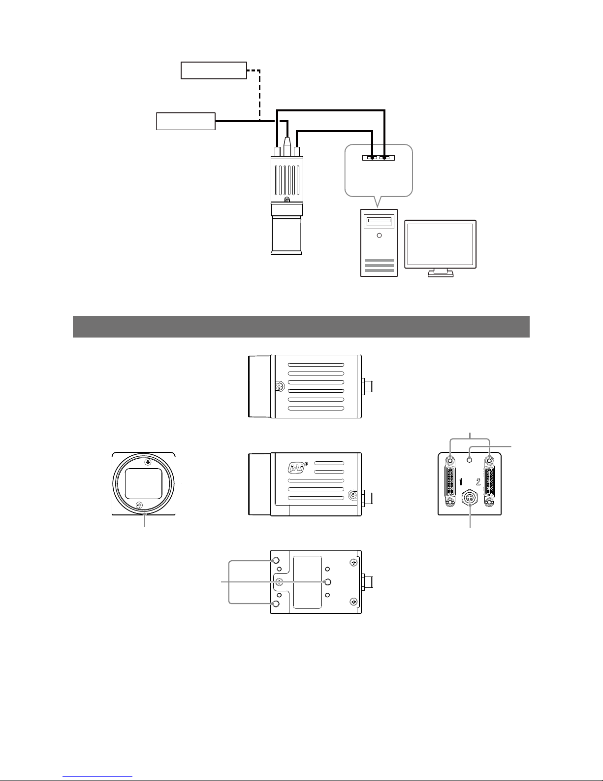
Connection example:
External trigger
AC adapter
Camera
Frame grabber
board
Computer
Parts Identification
②
③
④
①
⑤
1
Lens mount (C-mount)
Mount a C-mount lens, microscope adapter, etc. here.
Before mounting a lens, be sure to refer to “Step 2: Connecting Devices” (page 13) and confirm the
precautions for attaching a lens and the supported lens types.
Page 9
9
GO-2400M-PMCL / GO-2400C-PMCL
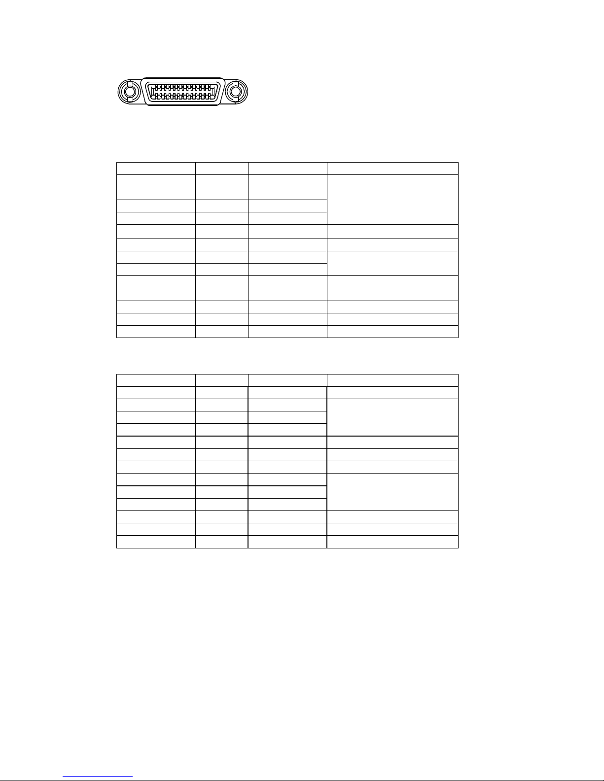
2 Mini Camera Link connector
Connect a cable that is compatible with Mini Camera Link (SDR) connectors here.
13
14
1
26
Camera side: HONDA HDR-EC26FYTG2-SL+
Port 1
Pin No. Input/output Signal Description
1, 26 Power Power
2(–), 15(+) Out X_OUT0 Data out
3(–), 16(+) Out X_OUT1
4(–), 17(+) Out X_OUT2
5(–), 18(+) Out X_Clk CL Clock
6(–), 19(+) Out X_OUT3 Data out
7(+), 20(–) In SerTC (RxD) LVDS Serial Control
8(–), 21(+) Out SerTFG (TxD)
9(–), 22(+) In CC1 (Trigger) JAI standard trigger
10(+), 23(–) In CC2 (Reserved)
11, 24 N.C
12, 25 N.C
13, 14 Shield Power Return
Port 2
Pin No. Input/output Signal Description
1, 26 Power Power
2(–), 15(+) Out Y_OUT0 Data out
3(–), 16(+) Out Y_OUT1
4(–), 17(+) Out Y_OUT2
5(–), 18(+) Out Y_Clk CL Clock
6(–), 19(+) Out Y_OUT3 Data out
7(+), 20(–) N.C
8(–), 21(+) Out Z_OUT0 Data out
9(–), 22(+) Out Z_OUT1
10(+), 23(–) Out Z_OUT2
11(–), 24(+) Out Z_Clk CL Clock
12(–), 25(+) Out Z_OUT3 Data out
13, 14 Shield Power Return
Page 10
10
GO-2400M-PMCL / GO-2400C-PMCL
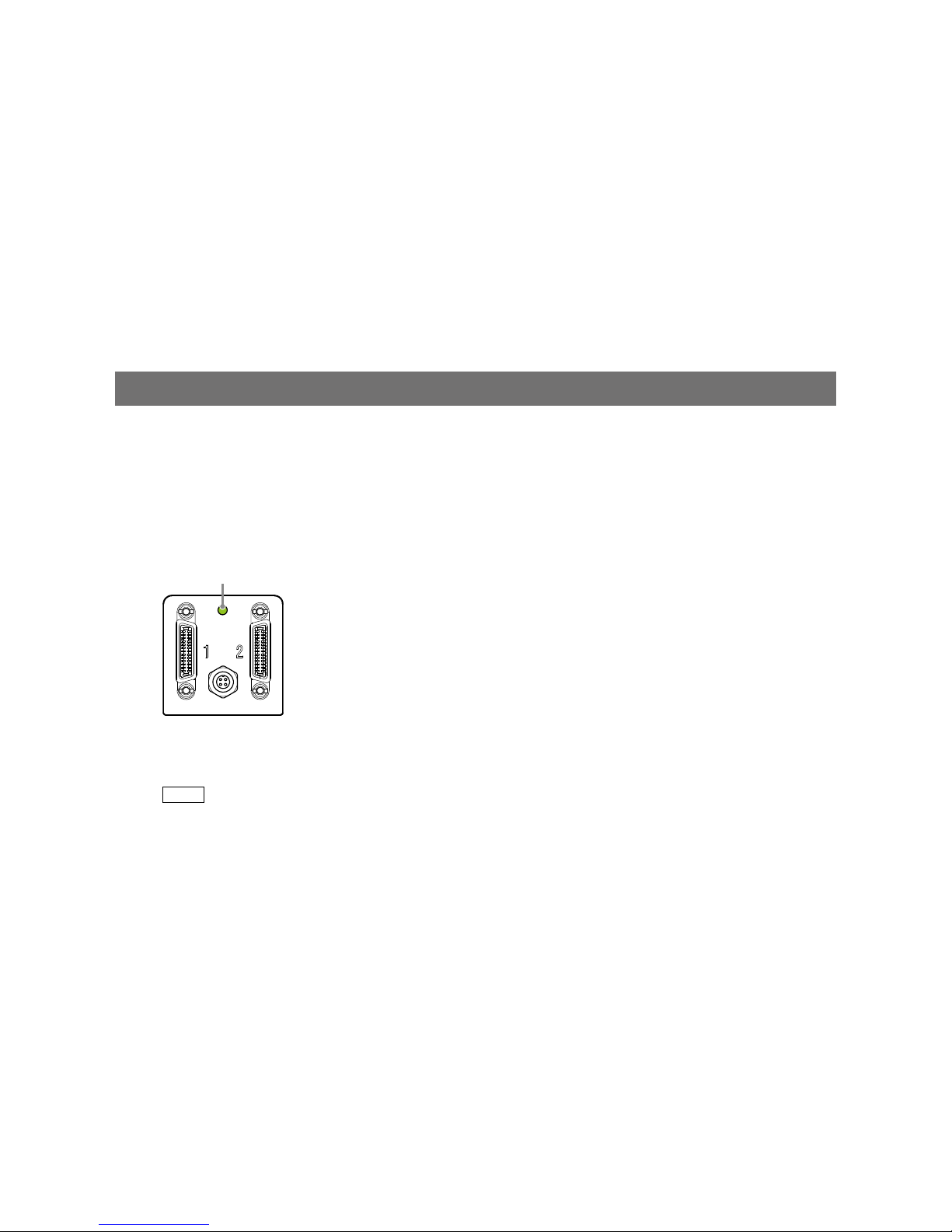
3 Power/trigger LED
Indicates the power and trigger input status.
LED status and camera status
LED Light Status
Power / trigger LED
Lit amber
Camera initializing.
Lit green
Operational and no triggers being input.
Blinking green
Operational and triggers being input.
The blinking interval is not related to the actual input interval
of the external trigger.
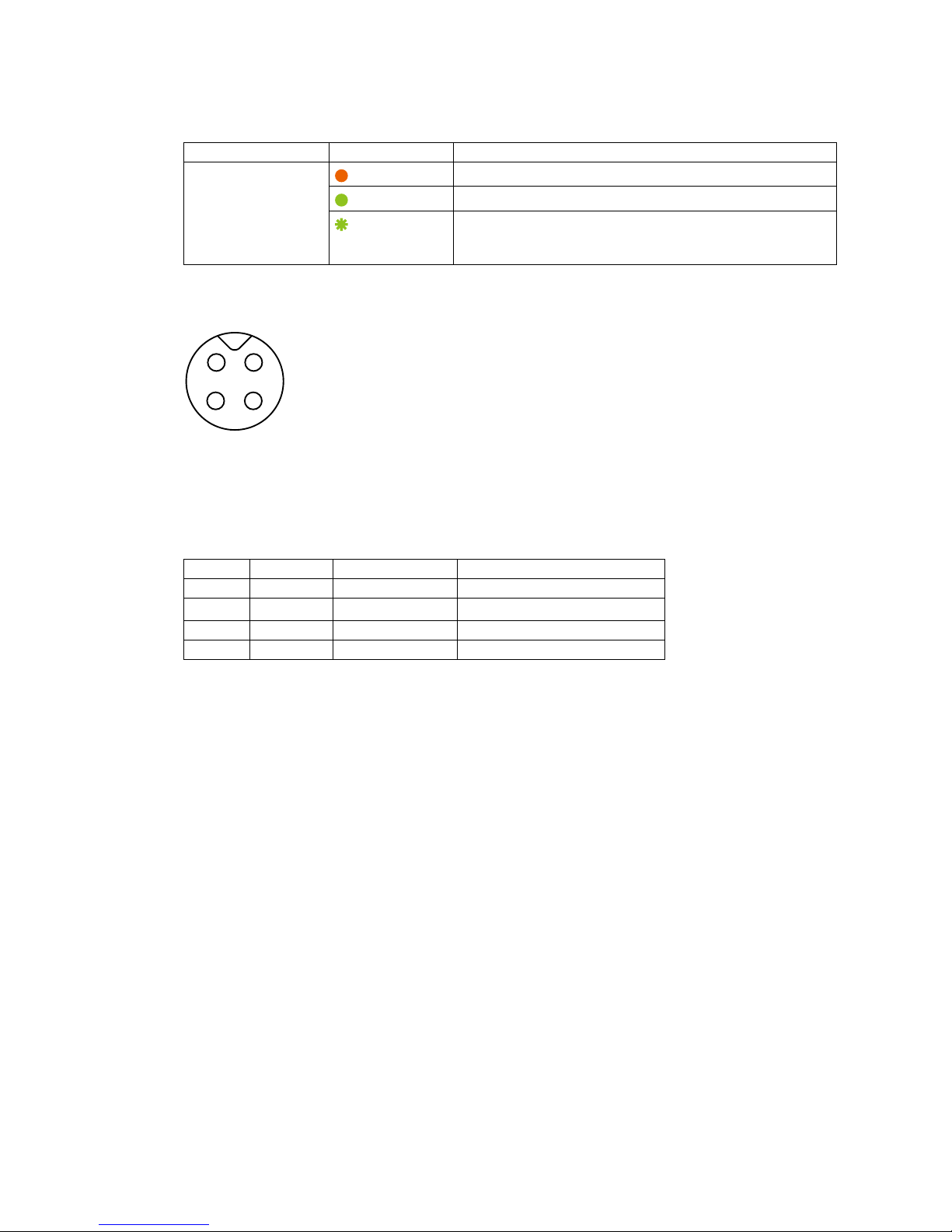
4 DC IN / trigger IN connector (4-pin round)
Connect the cable for a VA-044G Power Supply (optional) or for DC IN /trigger IN here.
1
2
3
4
Compatible connectors
Camera side: 09-3111-81-04 (Binder)
Cable side: 79-3108-52-04 (Binder) AWG 26
or
79-3108-32-04 (Binder) AWG 24
Pin No. Input/output Signal Description
1 Power In DC (+12 V) In DC 12 V to 24 V +/– 10%
2 In TTL In Line 4
3 Out TTL Out Line 1
4 Out Power GND COMMON GND
Page 11
11
GO-2400M-PMCL / GO-2400C-PMCL
Preparation
Preparation Flow
Step 1
Installing the Software (first time only)
Install the software for configuring and controlling the camera (JAI SDK) on the computer.
Step 2
Connecting Devices
Connect the lens, Camera Link cable, AC adapter, computer, and other devices.
Step 3
Verifying the Camera's Network Connection Status
Verify whether the camera is ready for use via the LEDs at the rear of the camera.
Step 4
Configuring Initial Settings for the Camera
• Configure the output format.
• Configure the exposure and external trigger settings.
Step 5
Adjusting the Image Quality
• Adjust the gain and white balance.
• Adjust the exposure (shutter).
Step 6
Configuring Various Other Settings
Configure various other settings as necessary.
Step 7
Saving the Settings
Save the current setting configurations as user memory.
Step 1: Installing the Software (first time only)
When using the camera for the first time, install the software for configuring and controlling the camera
(JAI SDK) on the computer.
When you install JAI SDK, JAI Camera Control Tool will also be installed.
1
Download the "JAI - Getting Started Guide" and JAI SDK from the JAI website.
URL http://www.jai.com/en/support/jai_sdk_and_control_tool
2
Refer to the "JAI - Getting Started Guide," and install JAI SDK on the computer.
The computer will restart when installation is complete.
Note
When the JAI SDK is installed, a camera driver for the interface is also part of the default installation. This
Vision Filter Driver is added to every NIC/port on the host computer. As the driver is also added to the NIC/
port for Internet connection, it may affect Internet access speed on some systems. If you think your Internet
speed is affected, configure the following settings to disable the filter driver on that port.
u
Open [Control Panel] [Network and Internet] [Connect to a network], and right-click the
port used for Internet connection to open the properties dialog box.
Page 12
12
GO-2400M-PMCL / GO-2400C-PMCL
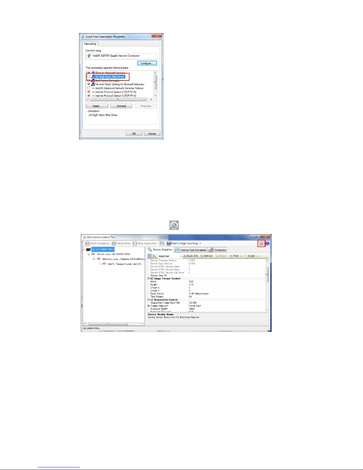
v
Clear the [JAI GigE Vision Filter Driver] checkbox, and save.
3
Verify the settings for using Camera Link.
The GO-2400-PMCL supports GenICam and Gen-CP. Check the following settings when
controlling the camera via JAI SDK.
Checking the frame grabber board's settings
Settings must be configured on the frame grabber board to enable Gen-CP support.
For details, refer to the operating instructions for each board.
Checking JAI SDK's settings
u
Start JAI Control Tool, and click the
(Settings) icon at the top right.
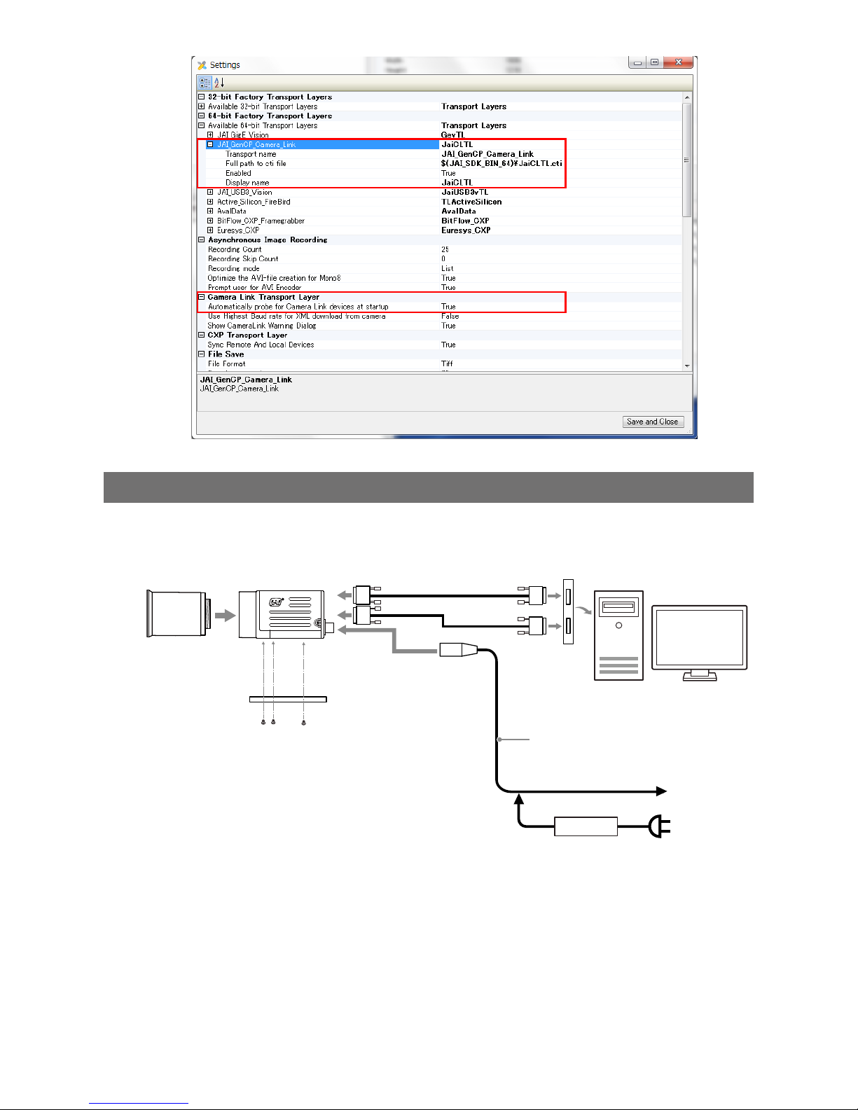
v
Check that the [JAI_GenCP_Camera_Link] and [Camera Link Transport Layer] settings are
configured as follows.
Page 13
13
GO-2400M-PMCL / GO-2400C-PMCL
Step 2: Connecting Devices
Connect the lens, Camera Link cable, AC adapter, and other necessary devices.
Attach the lens in a clean environment to prevent dust from adhering to the unit.
Camera body
2
Direct connection
(or MP-43 tripod adapter plate)
6
DC IN / trigger IN
connection cable (not supplied)
1
Lens
3
Camera Link cable
4
Frame grabber board
5
Computer
to external
trigger
or
7
AC adapter (not supplied)
Page 14
14
GO-2400M-PMCL / GO-2400C-PMCL
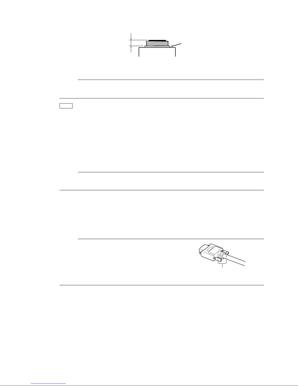
1
Lens
•C-mount lenses with lens mount protrusions of 9 mm or less can be attached.
9 mm or less
Lens mount protrusion
Lens
•The diagonal of the camera's CMOS image sensor is smaller at 13.4 mm than the 16 mm of 1-inch
models. To prevent vignetting and to obtain the optimal resolution, use a 1-inch lens.
Caution
• The maximum performance of the camera may not be realized depending on the lens.
• Attaching a lens with a mount protrusion longer than 9.1 mm may damage the lens or camera.
Note
The following formula can be used to estimate the focal length.
focal length = WD/(1 + W/w)
WD: Working distance (distance between lens and object)
W: Width of object
w: Width of sensor (11.3 mm on this camera)
2
Direct connection (or MP-43 tripod adapter plate)
When mounting the camera directly to a wall or other device, use screws that match the camera
locking screw holes on the camera. (Large: M3, small: M2, depth: 3 mm)
Use the supplied screws to attach the tripod adapter plate.
Caution
For heavy lenses, be sure to support the lens itself. Do not use configurations in which its weight is supported
by the camera.
3
Camera Link cable
Connect the Camera Link cable to the Mini Camera Link connector.
•Use a cable that supports the Camera Link standard and is compatible with Mini Camera Link
(SDR) connectors.
•Refer to the specifications of the cable for details on its bend radius.
•For details on the cable, see “2 Mini Camera Link connector” (page 9).
Caution
Secure the locking screws on the connector manually, and do not use a
driver. Do not secure the screws too tightly. Doing so may wear down the
screw threads on the camera. (Tightening torque: 0.291±0.049 N·m or
less)
4
Frame grabber board
Refer to the operating instructions of the frame grabber board, and configure settings on the
computer as necessary.
Secure manually.
Do not secure too tightly.
Page 15
15
GO-2400M-PMCL / GO-2400C-PMCL
5
Computer
Use a computer that meets the following requirements.
Operating system (OS):
Microsoft Windows Vista 7/8 32-bit/64-bit edition
CPU: Intel Core i3 or higher
Memory:
Windows 7/8 32-bit edition: DDR3, 4 GB or higher
Windows 7/8 64-bit edition: DDR3, 8 GB or higher
Graphics card: PCI-Express 3.0 or higher
6
DC IN / trigger IN connection cable
7
AC adapter (if desired)
Connect an AC adapter to the DC IN / trigger IN connector on the camera. For details on the
connector, see “4 DC IN / trigger IN connector (4-pin round)” (page 10).
The AC adapter is not required when using PoCL.
Step3: Verifying the Camera Connection Status
When the necessary devices are connected and power is supplied to the camera, the power / trigger
LED at the rear of the camera lights amber, and initialization of the camera starts.
When initialization is complete, the power / trigger LED lights green.
Verify whether power is being supplied to the camera and whether the camera is operational by
checking the rear LED.
Lit green
During normal status
For details on how to read the LED, see “LED status and camera status” (page 10) in the “Parts Identification”
section.
Note
Initialization of the camera will not complete unless connection with the host is established. If the power /
trigger LED does not switch to green within minutes of supplying power, check the Camera Link cable and
other connections. After initialization is completed once, the power / trigger LED will remain green, even if the
connection with the host is severed.
Page 16

16
GO-2400M-PMCL / GO-2400C-PMCL
Step 4: Configuring Initial Settings for the Camera
Start Control Tool, connect the camera to the frame grabber board, and configure initial settings for the
output format, exposure, external trigger, etc.
Connecting to the Camera to Control Tool
1
Start JAI Control Tool.
Cameras connected to the frame grabber board are detected, and a window appears. If they do
not appear, right-click inside the window and select [Search for Cameras].
2
Select the camera you want to configure.
3
Check that the settings of the selected camera are displayed.
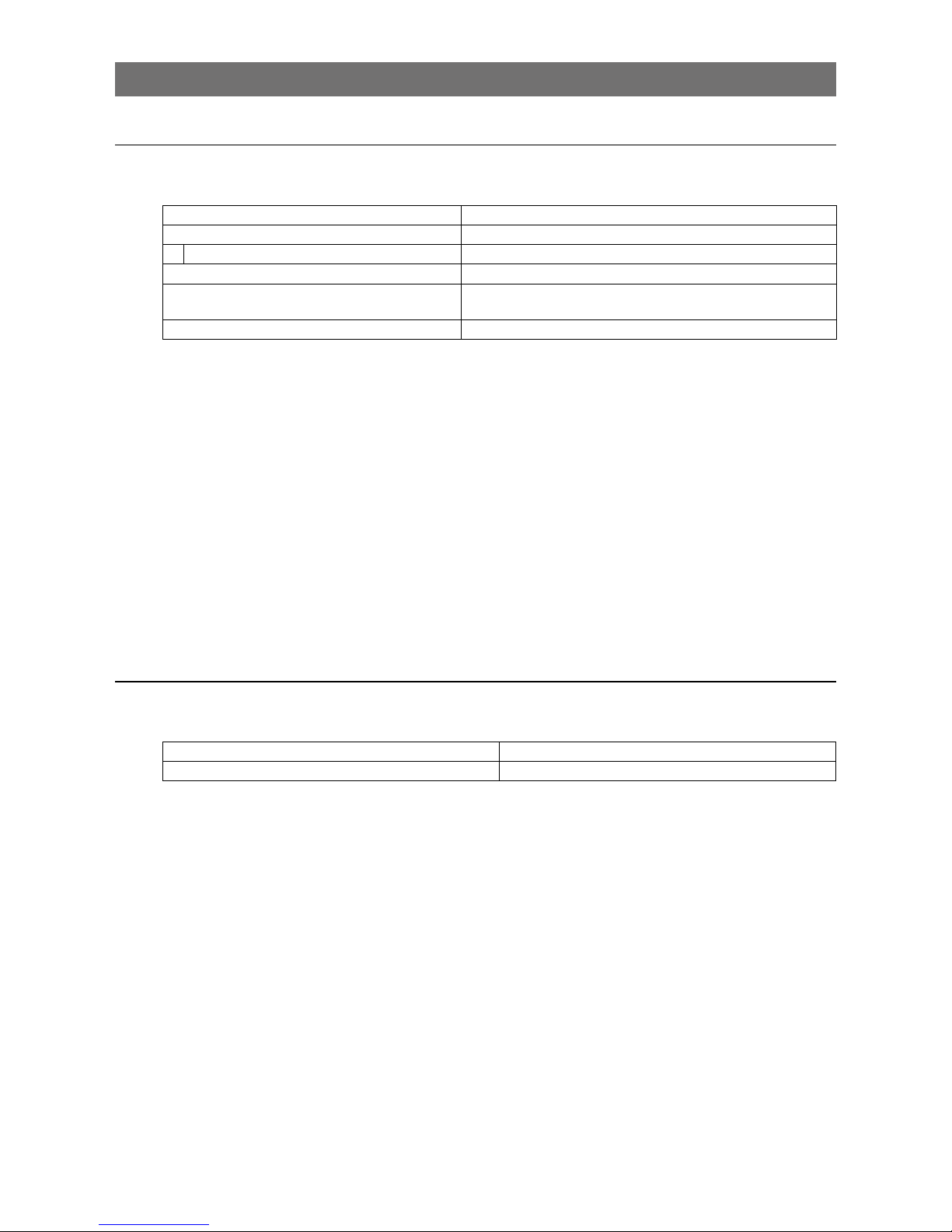
Configuring the Output Format
Configure the size, position, and pixel format of the images to be captured.
The factory default settings are as follows. Change the settings as necessary.
Factory default values
Item Default value
Image Format Control Width 1936 (pixels)
Height 1216 (pixels)
Offset X (horizontal position) 0 (pixels)
Offset Y (vertical position) 0 (pixels)
Pixel Format GO-2400M-PGE: 8 Bit
Monochrome
GO-2400C-PMCL: 8 Bit Bayer RG
You can specify the image capture area. For details, see “ROI (Regional Scanning Function)” (page 44).
Page 17
17
GO-2400M-PMCL / GO-2400C-PMCL
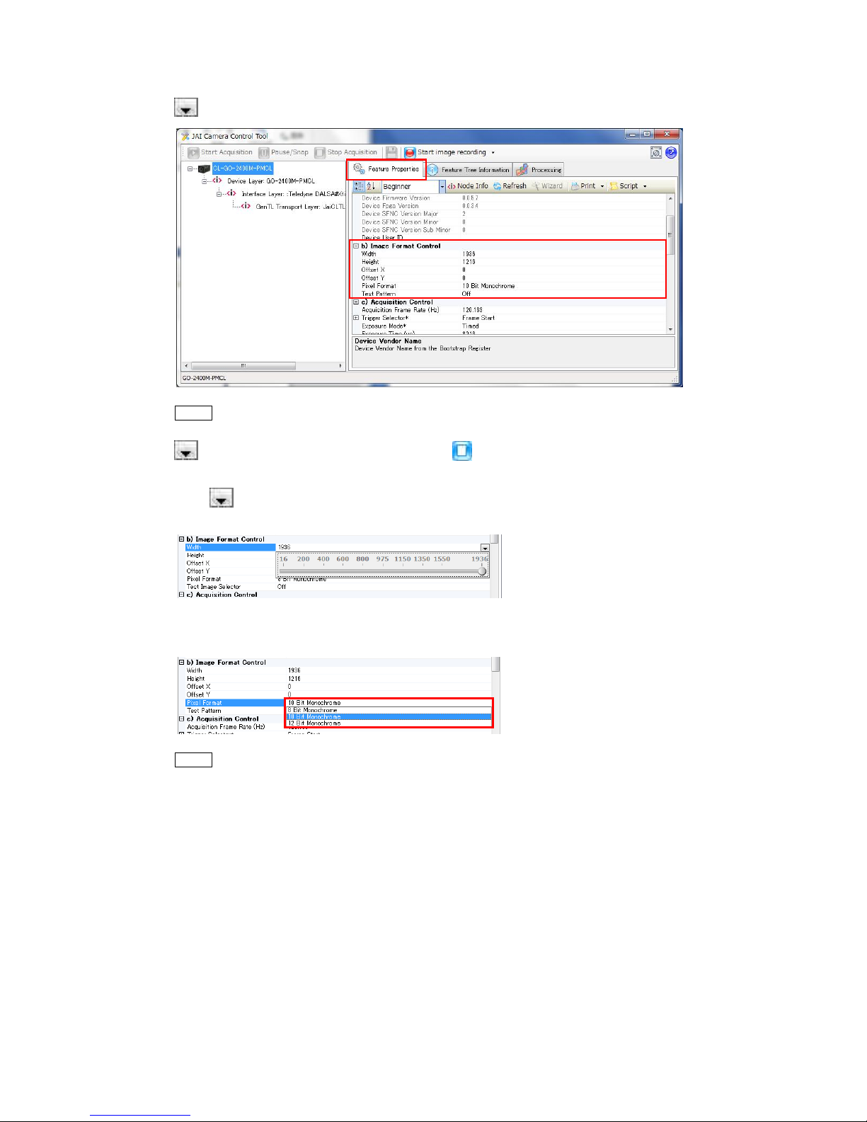
1
Select the [Feature Properties] tab, and select the item you want to configure under [Image
Format Control].
when a configurable item is selected.
Note
Settings can only be changed when image capture on the camera is stopped. If an item is grayed out and
does not appear even when you select it, click (Stop Acquisition) to stop image capture.
2
Click and change the setting value.
Example: When changing [Width]
Example: When changing [Pixel Format]
Note
Direct entry of numerical and text values is possible for some setting items.
Page 18
18
GO-2400M-PMCL / GO-2400C-PMCL
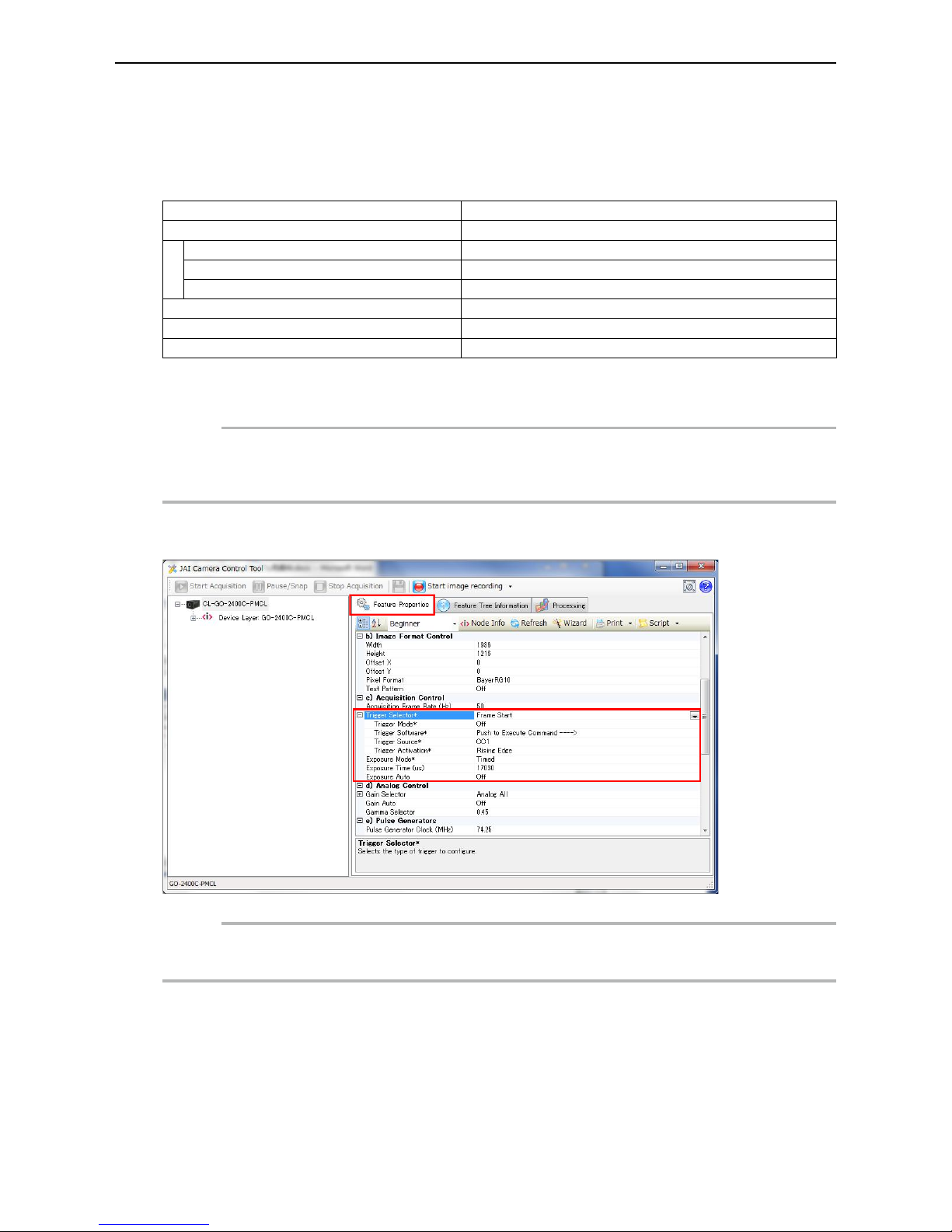
Configuring Exposure and External T rigger Settings
Configure settings related to exposure control methods and trigger control.
The factory default settings are as follows. Change settings as necessary, according to the intended
purpose or application.
Factory default values
Item Default value
Trigger Selector (trigger operation) Frame Start
Trigger Mode Off
Trigger Source (trigger signal source) Line7 CC1
Trigger Activation (trigger polarity) Rising Edge (rising edge of input signal)
Exposure Mode Timed (control via exposure time)
Exposure Time 20363 (µs)
Exposure Auto * Off
* This item is only enabled when [Exposure Mode] is set to [Timed].
Caution
When [Exposure Mode] is set to [Off], [Trigger Mode] cannot be set to [On]. Other settings may also be restricted
depending on the [Exposure Mode] setting, so be sure to set the [Exposure Mode] setting before configuring the
trigger settings.
Expand [Acquisition Control] and configure the following items.
Caution
Settings can only be configured when image capture on the camera is stopped. If an item is grayed out and the
setting cannot be changed, stop image capture beforehand.
Page 19
19
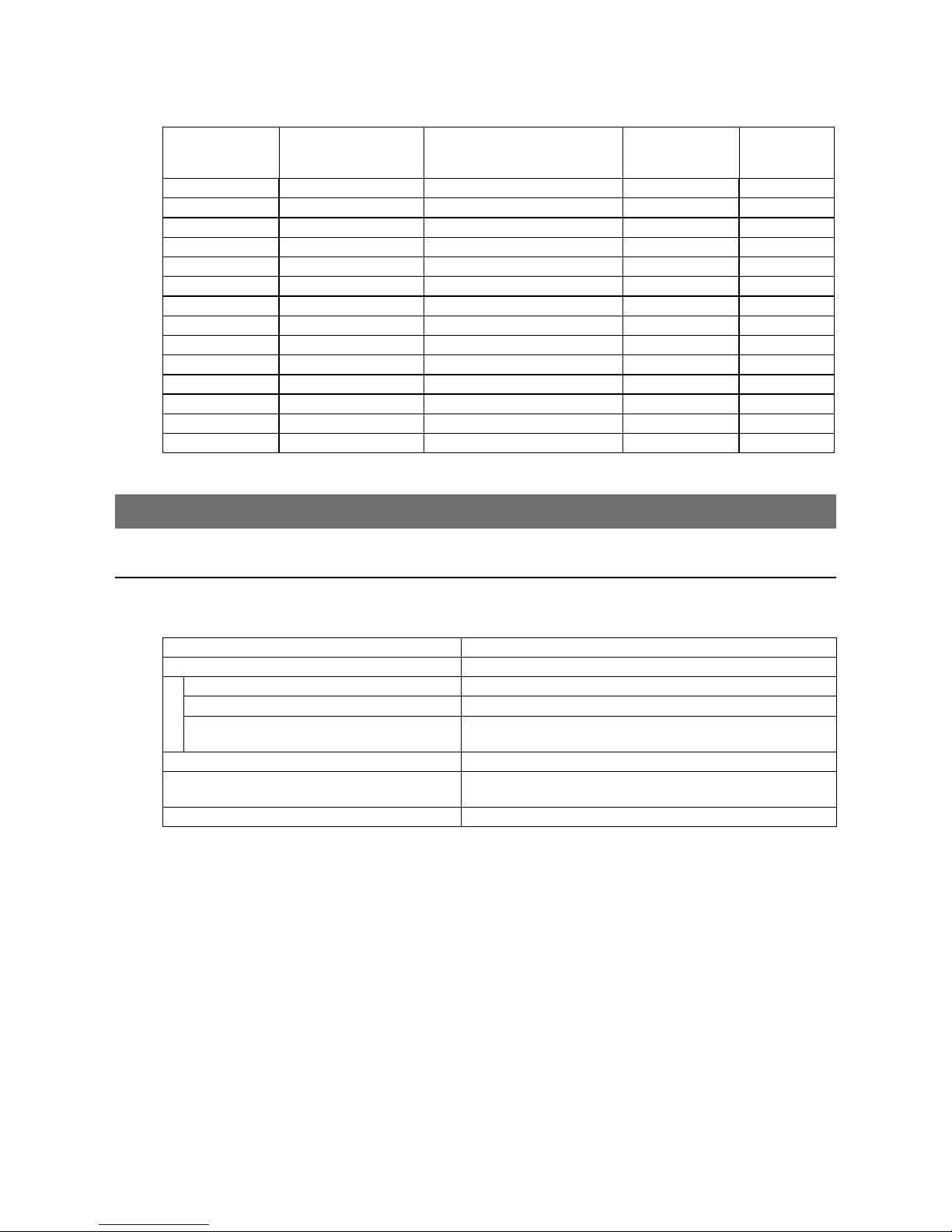
GO-2400M-PMCL / GO-2400C-PMCL
■ Exposure times
Exposure times vary depending on the Tap Geometry and CL Pixel Clock settings. Refer to the
following table.
Tap Geometry CL Pixel Clock (MHz) Max. exposure time value A
Longest
exposure time
[msec]
Shortest
exposure time
[usec]
1X2-1Y 37.125 Frame Period -342 [usec] 7999.658 79
1X2-1Y 74.25 Frame Period -171 [usec] 7999.829 40
1X2-1Y 84.85 Frame Period -162 [usec] 7999.838 38
1X3-1Y 37.125 Frame Period -252 [usec] 7999.748 59
1X3-1Y 74.25 Frame Period -114 [usec] 7999.886 27
1X3-1Y 84.85 Frame Period -100 [usec] 7999.900 24
1X4-1Y 37.125 Frame Period -172 [usec] 7999.828 40
1X4-1Y 74.25 Frame Period -86 [usec] 7999.914 20
1X4-1Y 84.85 Frame Period -81 [usec] 7999.919 19
1X8-1Y 37.125 Frame Period -88 [usec] 7999.912 21
1X8-1Y 74.25 Frame Period -63 [usec] 7999.937 15
1X8-1Y 74.25 Frame Period -81 [usec] 7999.919 19
1X8-1Y 84.85 Frame Period -63 [usec] 7999.937 15
1X8-1Y 84.85 Frame Period -81 [usec] 7999.919 19
Control via External Triggers
When Controlling the Exposure Time Using Specified Exposure Times
Configure the settings as follows.
Item Setting value / selectable range
Trigger Selector (trigger operation) Frame Start
Trigger Mode On
Trigger Source (trigger signal source) Any
Trigger Activation (trigger polarity) Rising Edge (rising edge of input signal), Falling Edge (falling
edge of input signal)
Exposure Mode Timed (control via exposure time)
Exposure Time Varies depending on the Tap Geometry and CL Pixel Clock
settings. *
1
Exposure Auto Off, Continuous
* 1 Max. value = [Acquisition Frame Rate] - Max. exposure time value A (“Exposure times” (page 19))
1
Set [Exposure Mode] to [Timed].
([Timed] is the default setting.)
2
Specify the exposure time in [Exposure Time].
The setting value for the exposure time can only be changed when [Exposure Auto] is set to [Off].
If [Exposure Auto] is set to [Continuous], temporarily set it to [Off] before changing the [Exposure
Time].
3
Set [Trigger Selector] to [Frame Start].
([Frame Start] is the default setting.)
4
Set [Trigger Mode] to [On].
Page 20

20
GO-2400M-PMCL / GO-2400C-PMCL
5
If necessary, change the [Trigger Source], [Trigger Activation], and [Exposure Auto]
settings.
When controlling the exposure time using the pulse width of the trigger input signal
Configure the settings as follows.
Item Setting value / selectable range
Trigger Selector (trigger operation) Frame Start
Trigger Mode On
Trigger Source (trigger signal source) Any
Trigger Activation (trigger polarity) Level High (high-level duration), Level Low (low-level
duration)
Exposure Mode Trigger Width (control via trigger width)
1
Set [Exposure Mode] to [Trigger Width] .
When you select [Trigger Width], [Trigger Mode] will automatically be set to [On].
2
Set [Trigger Selector] to [Frame Start].
([Frame Start] is the default setting.)
3
If necessary, change the [Trigger Source] and [Trigger Activation] settings.
Page 21
21
GO-2400M-PMCL / GO-2400C-PMCL
Control without external triggers
When controlling the exposure time using specified exposure times
Configure the settings as follows.
Item Setting value / selectable range
Trigger Selector (trigger operation) Frame Start
Trigger Mode Off
Exposure Mode Timed (control via exposure time)
Exposure Time Varies depending on the Tap Geometry and CL Pixel Clock
settings. *
1
Exposure Auto Off, Continuous
* 1 Max. value = [Acquisition Frame Rate] - Max. exposure time value A (“Exposure times” (page 19))
1
Set [Exposure Mode] to [Timed].
([Timed] is the default setting.)
2
Specify the exposure time in [Exposure Time].
The setting value for the exposure time can only be changed when [Exposure Auto] is set to [Off].
If [Exposure Auto] is set to [Continuous], temporarily set it to [Off] before changing the [Exposure
Time].
3
Set [Trigger Mode] to [On].
4
If necessary, change the [Exposure Auto] setting.
When not controlling the exposure time
Configure the settings as follows.
Item Setting value / selectable range
Exposure Mode Off
The exposure will be performed with an exposure time equal to 1 / frame rate.
* The [Exposure Time] setting will be disabled, and the [Exposure Auto] function cannot be used.
Page 22
22
GO-2400M-PMCL / GO-2400C-PMCL
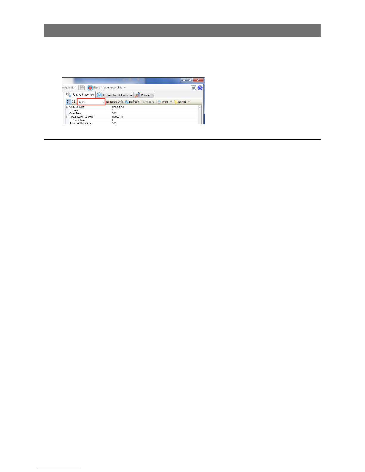
Step 5: Adjusting the Image Quality
Adjust the image quality using the gain and white balance (GO-2400C-PMCL only) functions.
To adjust the image quality
The display level must be changed from [Beginner] to [Guru].
Adjusting the Gain
Adjust the sensitivity via the analog gain (i.e., master gain).
For details on gain control, see “Gain Control” (page 39) in the "Main Functions" section.
■ Manual adjustment
1
Expand [Analog Control], and set [Gain Auto] to [Off].
([Off] is the default setting.)
2
Configure the gain.
u
Expand [Analog Control], and select the gain you want to configure in [Gain Selector].
•For the GO-2400M-PMCL, only [Analog All] (master gain) can be configured.
•For the GO-2400C-PMCL, [Analog All] (master gain), [Digital Red] (digital R gain), and
[Digital Blue] (digital B gain) can be configured individually.
v
Configure the gain value in [Gain].
•The [Digital All] (master gain) can be set to a value from x1 to x16 (0 dB to +24 dB) the
analog base gain value. The resolution is set in x0.01 steps (0.05 dB to 0.08 dB depending
on the setting value). Values are configured by multipliers. For example, the values set for x1
and x16 are 100 and 1600 respectively.
•For the GO-2400C-PMCL, the [Digital Red] (digital R gain) and [Digital Blue] (digital B gain)
can be set to a value from x0.45 to x5.62 (
–7 dB to +15 dB) the [Digital All] (master gain)
value. The resolution is set in 0.1 dB steps. Specify 0 for 0 dB, negative values for settings
below 0, and positive values for settings above 0.
Page 23

23
GO-2400M-PMCL / GO-2400C-PMCL
Adjusting the White Balance (GO-2400C-PMCL only)
Adjust the white balance using R, and B gain. The white balance can also be adjusted automatically.
■ Manual white balance adjustment
1
Expand [Analog Control], and set [Balance White Auto] to [Off].
([Off] is the default setting.)
2
Select the gain to configure in [Gain Selector], and set the gain value in [Gain].
■ Automatic white balance adjustment
1
Place a white sheet of paper or similar object under the same lighting conditions as the
intended subject, and zoom in to capture the white.
White objects near the subject, such as a white cloth or wall, can also be used.
Be sure to prevent the high-intensity spot lights from entering the screen.
2
Select the [Balance White Auto] tab, and click [Continuous] or [Once] depending on your
intended application.
The white balance is automatically adjusted.
Adjusting the Black Level
1
Expand [Analog Control] and select the black level you want to configure in [Black Level
Selector].
For the GO-2400M-PMCL, only [Digital All] (master black) can be configured.
For the GO-2400C-PMCL, [Digital All] (master black), [Digital Red] (digital R), and [Digital Blue]
(digital B) can be configured individually.
2
Specify the adjustment value in [Black Level].
Step 6: Configuring Various Other Settings
See “Settings List” (page 57), and configure settings as necessary.
Page 24
24
GO-2400M-PMCL / GO-2400C-PMCL
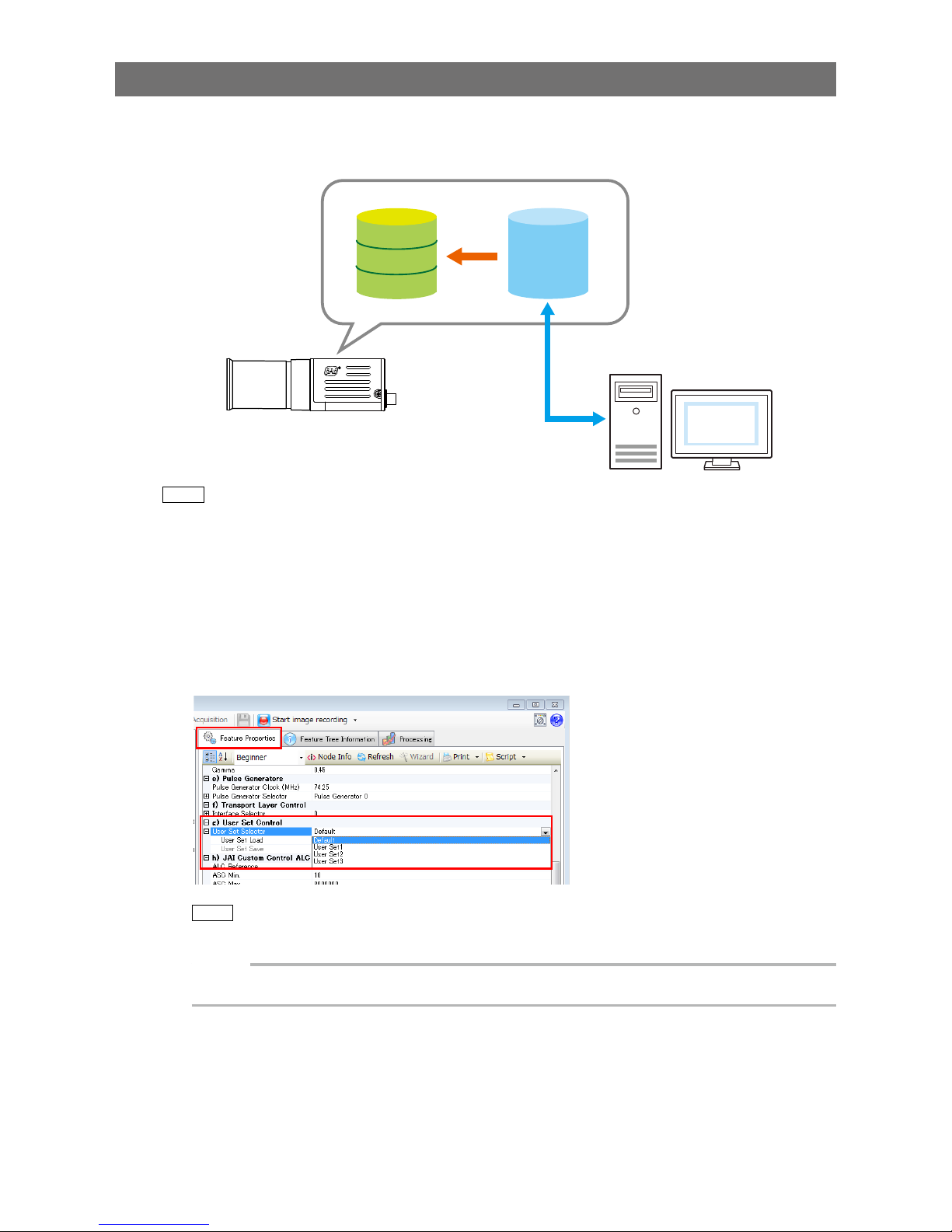
Step 7: Saving the Settings
The setting values configured in Control Tool will be deleted when the camera is turned off. By storing
current setting values to user memory, you can load and recall them whenever necessary. You can
save up to three sets of user memory settings (User Set1 to 3).
User memory Temporary memory
Current
setting
values
Control
Tool
Save
User Set1
User Set2
User Set3
Note
The setting values are not saved to the computer (Control Tool).
■ To save user settings
1
Stop image capture.
2
Expand [User Set Control] and select the save destination ([User Set1] to [User Set3]) in
[User Set Selector].
Note
The factory default setting values are stored in [Default] and cannot be overwritten.
Caution
Settings can only be saved when image capture on the camera is stopped.
Page 25

25
GO-2400M-PMCL / GO-2400C-PMCL
3
Select [User Set Save], and click [Execute 'User Set Save' Command].
The current setting values are saved as user settings.
■ To load user settings
1
Stop image capture.
User settings can only be loaded when image capture on the camera is stopped.
2
Select the settings to load (Default, and User Set1 to User Set3) in [User Set Selector].
3
Select [User Set Load], and click [Execute 'User Set Load' Command].
The selected user settings are loaded.
The next time the unit is started up, the settings selected in [User Set Selector] will be loaded automatically.
Page 26
26
GO-2400M-PMCL / GO-2400C-PMCL
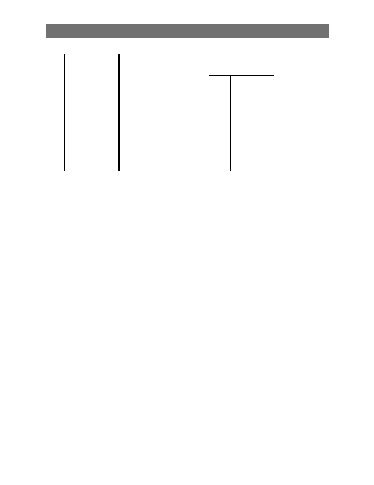
Basic Function Matrix
The combinations of settings for the basic functions that can be used together are as follows.
Exposure Mode
Frame Start Trigger
Exposure Time
ROI
Balance White Auto
*1
Gain Auto
Exposure Auto
Video Send Mode
Sensor Multi ROI
Trigger Sequence Mode
Command Sequence Mode
Off Off ×
×
× ×
Timed Off
×
Timed (EPS) On
× × ×
Trigger Width On ×
× × ×
× ×
* 1 Operates only on the GO-2400C-PMCL
Page 27
27
GO-2400M-PMCL / GO-2400C-PMCL
Main Functions
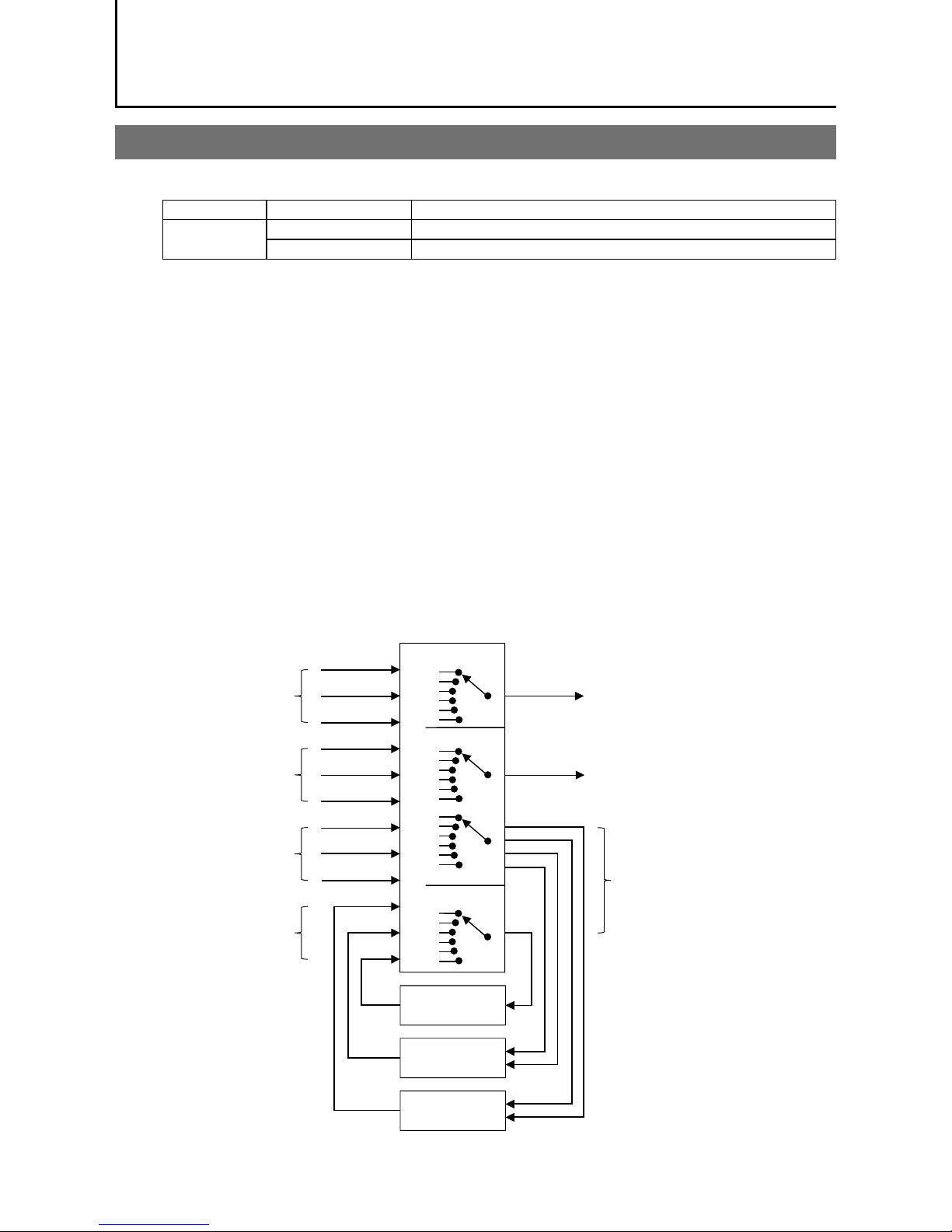
GPIO (Digital Input/Output Settings)
The unit can input/output the following signals to and from external input/output connectors.
External output TTL Out (Line1) DC IN / trigger IN connector (4-pin round)
External input TTL IN (Line4) DC IN / trigger IN connector (4-pin round)
CC1 (Line7) Camera Link cable
These signals can be used as triggers and other necessary signals within the camera or as signals
output from the camera to the system, such as those used for lighting equipment control.
In addition, a pulse generator for generating custom pulses and a NAND module for performing logic
operations are built into the camera. The two can be used together for a variety of purposes, such as
noise removal for trigger signals and phase adjustment for pulse outputs.
Such functions are generally referred to as GPIO functions.
Signals are selected as follows.
•When using external signals or the signals of each GPIO module as trigger signals:
Select in [Trigger Selector] > [Trigger Source].
•When selecting the signals to use for external outputs:
Select in [Line Selector] > [Line Source].
•When selecting the input signal for the NAND logic line:
Select in [Line Selector] > [Line Source].
•When selecting the clear signal for [Pulse Generator]:
Select in [Pulse Generator Selector] > [Pulse Generator Clear source].
GPIO block diagram
NAND Logic
NAND Logic
Pulse
Generator
Trigger Selector
PulseGenerator
Selector
Line Selector
Cross point switch
External input
Camera internal signal
User control signal
GPIO module signal
Trigger signal
External output
Signal to the GPIO module
Page 28
28
GO-2400M-PMCL / GO-2400C-PMCL
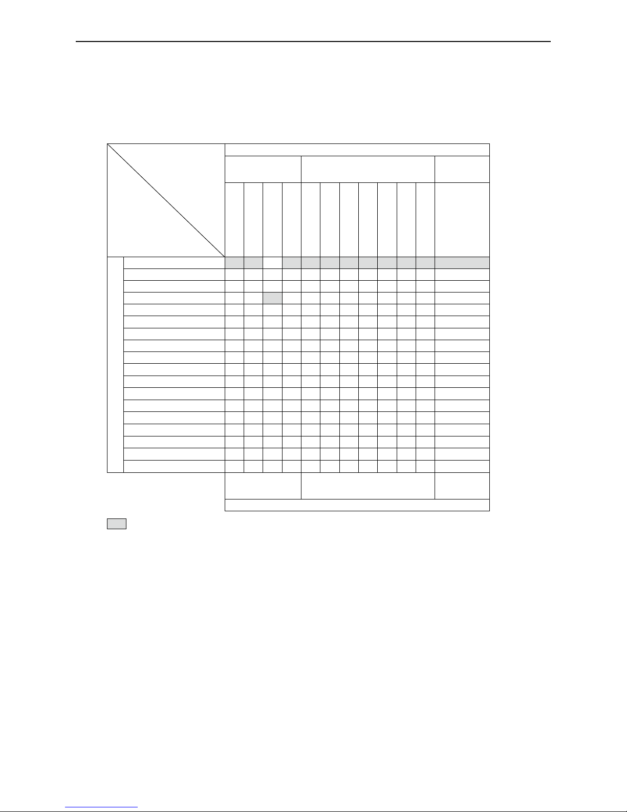
Valid Input/Output Combinations
The following signals can be used as sources for each output destination (Trigger Selector, Line
Selector, Pulse Generator Selector).
You can also connect two different sources to NAND paths in the GPIO and reuse the signal generated
there as a source for a different selector.
The combinations of source signals and output destinations are indicated in the following.
Selector
(Cross point
switch output)
Source signal
(Cross point
switch input)
Output destination
Trigger Selector Line Selector
Pulse
Generator
Selector
Acquisition Start
Acquisition Stop
Frame Start
Transfer Start
Line2 OPT Out 1
(GPIO 1)
Line2 OPT Out 2
(GPIO 2)
Time Stamp Reset
NAND 0 In 1
NAND 0 In 2
NAND 1 In 1
NAND 1 In 2
Pulse Generator 0
Signals to use as output
LOW
HIGH
Line4 TTL In
Line7 CC1
NAND 0 Out
× ×
NAND 1 Out
× ×
Pulse Generator 0
×
User Output 0
User Output 1
Software Trigger
× ×
× × × × ×
Action 1
× × × × × × ×
Action 2
× × × × × × ×
FVAL
× × × ×
LVAL
× × × ×
×
Exposure Active
× × × ×
Frame Trigger Wait
× × × ×
Frame Active
× × × ×
Acquisition Trigger Wait
× × × ×
Trigger Source Line Source
Pulse
Generator
Clear Source
Use
: Indicates default values for each selector. “Factory default values” (page 18) shows the
default values for [Frame Start].
Page 29
29
GO-2400M-PMCL / GO-2400C-PMCL
Camera Output Formats
The GO-2400-PMCL supports a variety of output formats.
The following tap geometries are supported.
The settings on the frame grabber board must be configured to match the tap geometry setting on the
camera. For details configuring frame grabber board settings, refer to the operating instructions for
each board.
Tap Geometry CL Configuration IP Bypass Off IP Bypass On
1X2-1Y Base bit: 8/10 bit: 8/10/12
1X3-1Y Base bit: 8 bit: 8
1X3-1Y Medium bit: 10 bit: 10/12
1X4-1Y Medium bit: 8/10 bit: 8/10/12
1X8-1Y Full bit: 8 bit: 8
1X8-1Y 80-bit bit: 10 bit: 10
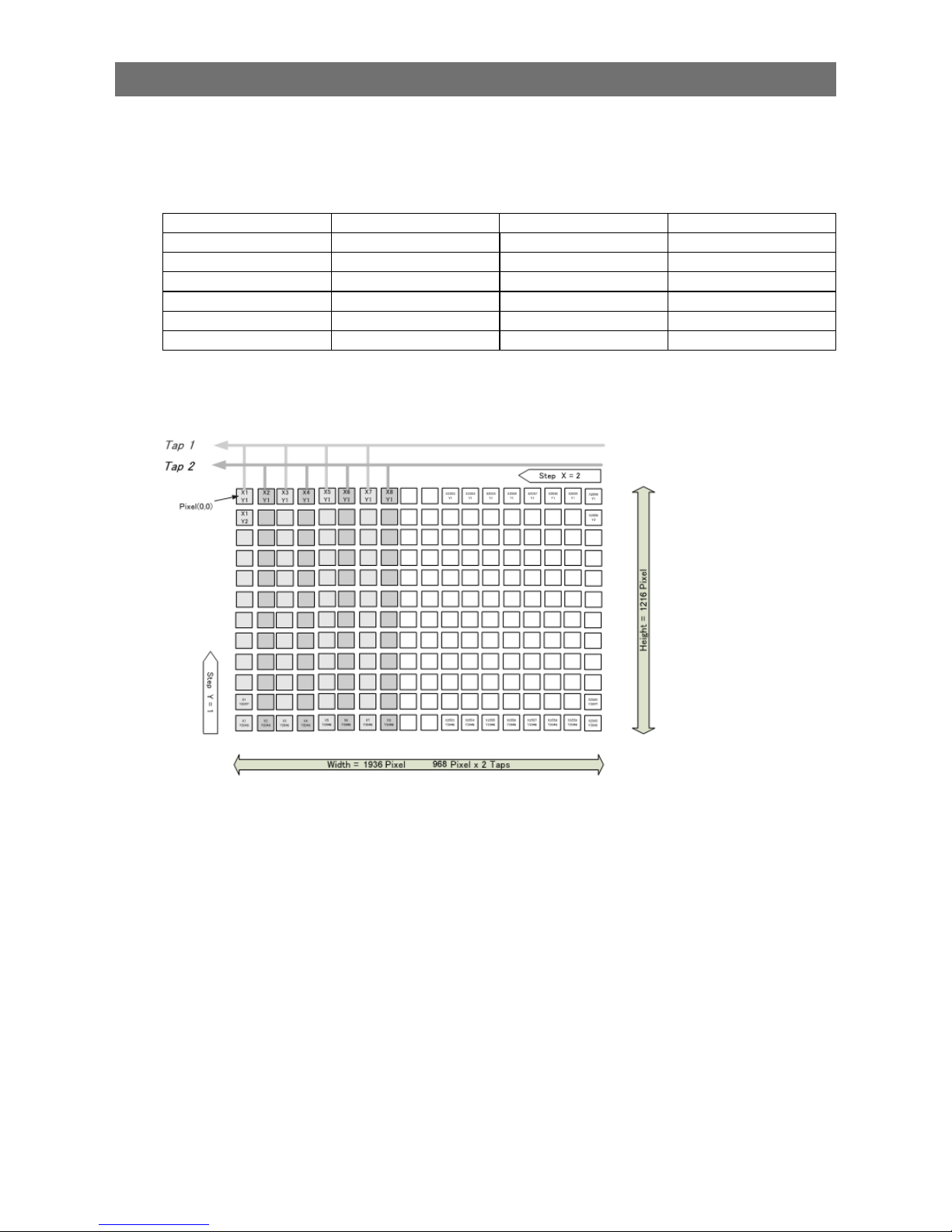
■ 1X2-1Y
1X2-1Y is a 2-tap output format as defined in GenICam tap geometry.
Page 30
30
GO-2400M-PMCL / GO-2400C-PMCL
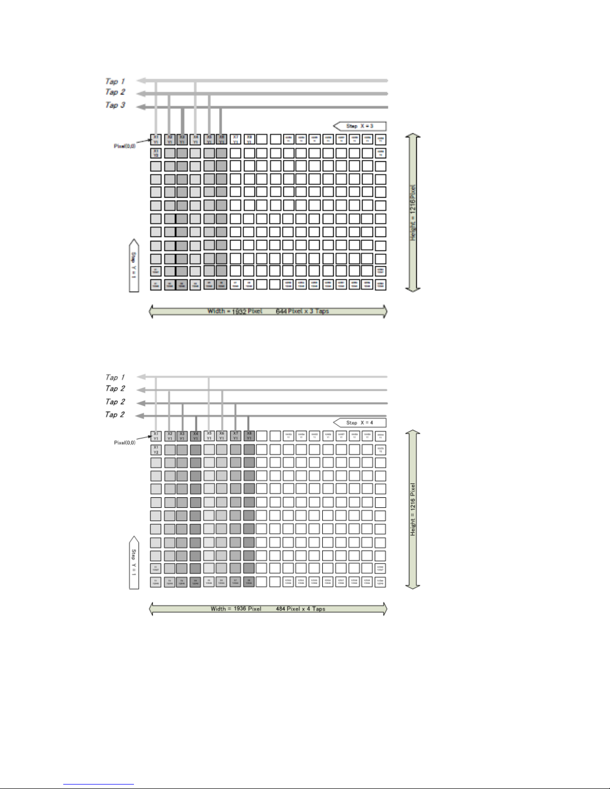
■ 1X3-1Y
1X3-1Y is a 3-tap output format as defined in GenICam tap geometry.
■ 1X4-1Y
1X4-1Y is a 4-tap output format as defined in GenICam tap geometry.
Page 31

31
GO-2400M-PMCL / GO-2400C-PMCL
■ 1X8-1Y (CL)
1X8-1Y (CL) is a 8-tap output format as defined in GenICam tap geometry.
■ Cable length reference
The following is a reference for the length of cable you can use based on the Camera Link clock*1.
CL Pixel Clock [MHz] CL cable length
37.125 10 m
74.25 7 m
84.85 3 m
*1 The length of cable you can use will also vary depending on type and maker.
Acquisition Control (Image Acquisition Controls)
Perform operations and configure settings related to image capture in [Acquisition Control].
On the GO-2400-PMCL, acquisition control always operates in [Continuous] mode.
Changing the Frame Rate
When [Trigger Mode] is disabled, you can change the frame rate in [Acquisition Frame Rate].
Note
• The shortest frame period varies depending on the ROI, pixel format, and binning mode selected. The longest
frame period is 0.125 Hz (8 sec.).
• When [Trigger Mode] is enabled, the [Acquisition Frame Rate] setting is disabled.
Page 32

32
GO-2400M-PMCL / GO-2400C-PMCL
■ Maximum frame rate period formula
•<Maximum output frame rate>
During [Continuous] mode: 1 / ((Height_s + 40) × Hperiod)
During [Trigger Mode]: 1 / (Exposure Time [sec] + (Height_s + 40) × Hperiod)
Full size (regardless of Binning Vertical and Binning Horizontal settings)
Tap Geometry CL Pixel Clock (MHz) H Period [sec] Frame Rate [Hz]
1X2-1Y 37.125 26.290 × 10
-6
30.28
1X2-1Y 74.25 13.145 × 10
-6
60.57
1X2-1Y 84.85 12.444 × 10
-6
63.98
1X3-1Y 37.125 19.421 × 10
-6
41.00
1X3-1Y 74.25 8.795 × 10
-6
90.53
1X3-1Y 84.85 7.731 × 10
-6
102.99
1X4-1Y 37.125 13.253 × 10
-6
60.08
1X4-1Y 74.25 6.626 × 10
-6
120.15
1X4-1Y 84.85 6.222 × 10
-6
127.96
1X8-1Y 37.125 6.734 × 10
-6
118.23
1X8-1Y 74.25 4.848 × 10
-6
164.21
1X8-1Y 74.25 6.222 × 10
-6
127.96
1X8-1Y 84.85 4.808 × 10
-6
165.59
1X8-1Y 84.85 6.222 × 10
-6
127.96
Exposure Mode
The following exposure modes are available on the camera.
Exposure Mode Description
Off Exposure control is not performed (free-running operation).
Timed Mode in which exposure time is pre-set by the user. Images can be captured with the
trigger off (free-running) or with trigger on (EPS).
Trigger Width Mode in which control of the exposure time is performed using the pulse width of the
trigger input signal. The exposure time will be the same as the pulse width of the
trigger input signal. This allows long exposure.
The settings for exposure control and triggers are related to each other. Be sure to configure the settings
described in “Configuring Exposure and External Trigger Settings” (page 18).
Page 33

33
GO-2400M-PMCL / GO-2400C-PMCL
Image Output Timing
■ Vertical timing
Tap
Geometry
CL
PixelClock
[MHz]
H
Frequency
(KHz)
FVAL
BlankingLine
[A]
FVALValid
Line [B]
Total
FrameLine [C]
Total Frame
Period (msec)
Frame Rate
(Hz)
Vertical
ROI
ALL
40 Height Height + 40 (Height +
40) / H Freq
H Freq*1000 /
Height + 40
1X2-1Y
(Full)
37.125 38.038 40 1216 1256 33.020 30.28
74.25 76.076 40 1216 1256 16.510 60.57
84.85 80.357 40 1216 1256 15.630 63.98
1X3-1Y
(Full)
37.125 51.491 40 1216 1256 24.393 41.00
74.25 113.706 40 1216 1256 11.046 90.53
84.85 129.355 40 1216 1256 9.710 102.99
1X4-1Y
(Full)
37.125 75.457 40 1216 1256 16.645 60.08
74.25 150.915 40 1216 1256 8.323 120.15
84.85 160.714 40 1216 1256 7.815 127.96
1X8-1Y
(Full)
37.125 148.500 40 1216 1256 8.458 118.23
74.25_8 206.250 40 1216 1256 6.090 164.21
74.25_10 160.714 40 1216 1256 7.815 127.96
84.85_8 207.983 40 1216 1256 6.039 165.59
84.85_10 160.714 40 1216 1256 7.815 127.96
Page 34

34
GO-2400M-PMCL / GO-2400C-PMCL
■ Horizontal timing
Tap Geometry
CL Pixel
Clock (MHz)
Line
BlankingClock
[A]
LineValid clock
[B]
Total Line clock
[C]
Total Line Period
(usec) [C]
Line Rate (KHz)
[C]
Horizontal
ROI
ALL (1936/Tap)
- Width + 8
Width
1X2-1Y
(Full)
37.125 8 968 976 26.290 38.038
74.25 8 968 976 13.145 76.076
84.85 8 968 1056 12.444 80.357
1X3-1Y
(Full)
37.125 76 645 721 19.421 51.491
74.25 8 645 653 8.795 113.706
84.85 11 645 656 7.731 129.355
1X4-1Y
(Full)
37.125 8 484 492 13.253 75.457
74.25 8 484 492 6.626 150.915
84.85 44 484 528 6.222 160.714
1X8-1Y
(Full)
37.125 8 242 250 6.734 148.500
74.25_8 118 242 360 4.848 206.250
74.25_10 220 242 462 6.222 160.714
84.85_8 166 242 408 4.808 207.983
84.85_10 286 242 528 6.222 160.714
Page 35

35
GO-2400M-PMCL / GO-2400C-PMCL
Trigger Control
The camera allows Frame Start trigger controls to be performed via external trigger signals.
The Frame Start trigger allows exposure control via the trigger signal inputs.
The settings for exposure control and triggers are related to each other. Be sure to configure the settings
described in “Configuring Exposure and External Trigger Settings” (page 18).
Shortest Repetition Period for Triggers
The reciprocal of the maximum frame rate is the time required to output one frame. The shortest
repetition periods for triggers cannot be lower than that value.
■ When [Exposure Mode] is [Timed]
Example: When [Trigger Source] is set to [Line7 CC1]
Scanning range
Shortest period of trigger [ms], exposure condition: minimum
exposure time
1X2-1Y 1X3-1Y 1X4-1Y 1X8-1Y
84.85 MHz
8 bit
84.85 MHz
8-bit
84.85 MHz
8-bit
84.85 MHz
8-bit
Full 15670 9736 7836 6046
ROI 2/3 (Height = 810) 10618 6597 5310 4094
ROI 1/2 (Height = 608) 8104 5035 4053 3122
ROI 1/4 (Height = 304) 4321 2685 2161 1661
ROI 1/8 (Height = 152) 2429 1510 1216 930
Binning Vertical (968 × 608)* 15670 9736 7836 6046
* GO-2400M-PMCL only
Exposure and readout cannot overlap on the GO-2400-PMCL. The above table indicates the shortest
trigger periods for the shortest exposure times. By adding the value of the exposure time you are
using to the values in the table, you can determine the shortest trigger periods under your own usage
environment.
0.25 us
FVAL
A
B
Frame Active
Frame Trigger Wait
0.25 us
Sensor
Exposure
Trigger
C
Exposure Active
Exposure duration
Next trigger disabled
Next
trigger
input
enabled
Data output duration
(= Height x Line Period)
Page 36

36
GO-2400M-PMCL / GO-2400C-PMCL
Tap
Geometry
CL Pixel
Clock
(MHz)
Period From
Trigger start
edge to
Exposure start
[A] (usec)
Period from
Exposure
endTo FVAL
start [B] (usec)
Period FVAL
end to next
trigger start
[C] (usec)
Max Exposure
[msec]
Min Exposure
[usec]
Horizontal
ROI
ALL
Framerate
– 13/H Freq
3/H Freq
+ 22×0.013
1X2-1Y
(Full)
37.125 80 884
≥ 89
7999.658 79
74.25 40 452
≥ 37
7999.829 40
84.85 38 428
≥ 34
7999.838 38
1X3-1Y
(Full)
37.125 60 654
≥ 65
7999.748 59
74.25 27 300
≥ 11
7999.886 27
84.85 24 263
≥ 24
7999.900 24
1X4-1Y
(Full)
37.125 41 454
≥ 37
7999.828 40
74.25 21 228
≥ 18
7999.914 20
84.85 20 214
≥ 17
7999.919 19
1X8-1Y
(Full)
37.125 22 232
≥ 17
7999.912 21
74.25_8 16 168
≥ 13
7999.937 15
74.25_10 20 214
≥ 19
7999.919 19
84.85_8 15 167
≥ 2.1
7999.937 15
84.85_10 20 214
≥ 19
7999.919 19
Smallest input pulse width of trigger signal: 10 µS or more
■ When [Exposure Mode] is [Trigger Width]
Scanning range
Shortest period of trigger [ms], exposure condition: minimum
exposure time
1X2-1Y 1X3-1Y 1X4-1Y 1X8-1Y
84.85 MHz
8-bit
84.85 MHz
8-bit
84.85 MHz
8-bit
84.85 MHz
8-bit
Full 15670 9736 7836 6046
ROI 2/3 (Height = 810) 10618 6597 5310 4094
ROI 1/2 (Height = 608) 8104 5035 4053 3122
ROI 1/4 (Height = 304) 4321 2685 2161 1661
ROI 1/8 (Height = 152) 2429 1510 1216 930
Binning Full (968 × 608)* 15670 9736 7836 6046
* GO-2400M-PMCL only
Exposure and readout cannot overlap on the GO-2400-PMCL. The above table indicates the shortest
trigger periods for the shortest exposure times. By adding the value of the exposure time you are
using to the values in the table, you can determine the shortest trigger periods under your own usage
environment.
Page 37

37
GO-2400M-PMCL / GO-2400C-PMCL
0.25 us
FVAL
A
B
Frame Active
Frame Trigger Wait
0.25 us
Sensor
Exposure
Trigger
C
Exposure Active
D
Exposure duration
Next trigger disabled
Next
trigger
input
enabled
Data output duration
(= Height x Line Period)
Tap
Geometry
CL Pixel
Clock
(MHz)
Period From
Trigger start
edge to
Exposure start
[A] (usec)
Period from
Exposure
endTo FVAL
start [B] (usec)
Period FVAL
end to next
trigger start
[C] (usec)
Period From
Trigger end
edge to
Exposure end
[D] (usec)
Min Exposure
[usec]
Horizontal
ROI
ALL
3/H Freq
+ 22×0.013
1X2-1Y
(Full)
37.125 80 885
≥ 88
80 79
74.25 41 452
≥ 36
41 40
84.85 39 428
≥ 33
39 38
1X3-1Y
(Full)
37.125 60 654
≥ 64
60 59
74.25 27 300
≥ 9.3
27.4 27
84.85 24 264
≥ 23
25 24
1X4-1Y
(Full)
37.125 41 452
≥ 36
41 40
74.25 20 227
≥ 17
20.8 20
84.85 19 214
≥ 16
19.6 19
1X8-1Y
(Full)
37.125 21 231
≥ 17
21.2 21
74.25_8 16 169
≥ 12
16 15
74.25_10 20 215
≥ 18
20 19
84.85_8 16 168
≥ 1.2
16 15
84.85_10 20 214
≥ 19
20 19
Smallest input pulse width of trigger signal: minimum exposure time of each mode
■ During normal continuous operation
When using an application that does not require external triggers, the following applies.
Scanning range
Shortest period [ms]
1X2-1Y 1X3-1Y 1X4-1Y 1X8-1Y
84.85 MHz
8-bit
84.85 MHz
8-bit
84.85 MHz
8-bit
84.85 MHz
8-bit
Full 15.630 9.710 7.815 6.039
ROI 2/3 (Height = 810) 10.578 6.571 5.289 4.087
ROI 1/2 (Height = 608) 8.064 5.009 4.032 3.116
ROI 1/4 (Height = 304) 4.281 2.659 2.140 1.654
ROI 1/8 (Height = 152) 2.389 1.484 1.195 0.923
Binning Full (968 × 608)* 15.630 9.710 7.815 6.039
*
GO-2400M-PMCL only
Page 38

38
GO-2400M-PMCL / GO-2400C-PMCL
When [Exposure Mode] is [Off]
FVAL
X1
Sensor
Exposure
Exposure Active
X2
Exposure duration
Tap Geometry CL Pixel Clock (MHz)
Exposure stop period [X1]
(usec)
Period From FVAL end to
Exposure end [min] [X2]
(usec)
Horizontal ROI ALL 13/H Freq
1X2-1Y
(Full)
37.125 342
≥ 167
74.25 171
≥ 75
84.85 162
≥ 69
1X3-1Y
(Full)
37.125 252
≥ 121
74.25 114
≥ 35
84.85 100
≥ 45
1X4-1Y
(Full)
37.125 172
≥ 80
74.25 86
≥ 36
84.85 80
≥ 37
1X8-1Y
(Full)
37.125 88
≥ 37
74.25_8 63
≥ 26
74.25_10 81
≥ 36
84.85_8 63
≥ 8.9
84.85_10 81
≥ 36
When [Exposure Mode] is [Timed]
FVAL
X1
Sensor
Exposure
Exposure Active
Exposure duration
Page 39

39
GO-2400M-PMCL / GO-2400C-PMCL
Tap Geometry
CL Pixel Clock
(MHz)
Period From
FVAL end to
Exposure end
[X1] (usec)
Max Exposure [msec]
Min Exposure
[usec]
Horizontal ROI ALL
Framerate-13/H Freq 3H + 22 x 0.013
1X2-1Y
(Full)
37.125 143 to 169 7999.658 79
74.25 64 to 77 7999.829 40
84.85 59 to 72 7999.838 38
1X3-1Y
(Full)
37.125 104 to 124 7999.748 59
74.25 29 to 39 7999.886 27
84.85 40 to 48 7999.900 24
1X4-1Y
(Full)
37.125 64 to 78 7999.828 40
74.25 32 to 40 7999.914 20
84.85 30 to 37 7999.919 19
1X8-1Y
(Full)
37.125 32 to 40 7999.912 21
74.25_8 24 to 29 7999.937 15
74.25_10 32 to 39 7999.919 19
84.85_8 7.3 to 12 7999.937 15
84.85_10 33 to 39 7999.919 19
Gain Control
[Analog All] can be used for gain control for both the monochrome and color camera. [Analog All]
(master gain) uses the sensor's internal gain function and consists of analog gain + digital gain.
Analog gain is used for lower gain, and analog gain + digital gain is used when the gain becomes
high. R and B can be configured individually as digital gain on the GO-2400C-PMCL.
For details on how to configure the settings, see “Adjusting the Gain” (page 22).
The relationship between the gain setting value, gain amplification, and dB value is as follows. For
example, a gain amplification of x5.62 will be 15 dB.
For monochrome
x16
x1
1600
100
24dB
0dB
Gain
setting
value
Gain
amplification
Gain adjustment range (monochrome)
Page 40

40
GO-2400M-PMCL / GO-2400C-PMCL
For color
Master Master
Gain
setting
value
Gain
amplification
Gain setting
value (scaling)
Gain adjustment range (Bayer color)
X89.12
X16
X7.15
X5.62
X1
X0.45
1600
0
37876 (X5.62)
0 (X1)
–4533 (X0.45)
R&B
Red
Blue
39dB
-7dB
0dB
24dB
15dB
0dB
–7dB
15dB
0dB
–7dB
15dB
37876 (X5.62)
0 (X1)
–4533 (X0.45)
LUT (Lookup T able)
The LUT function is used to generate a non-linear mapping between signal values captured on the
sensor and those that are output from the camera. You can specify the output curve using 256 setting
points (indexes) on the GO-2400M/C-PMCL.
■ To use the LUT function
Configure the settings as follows.
Item
Setting value / selectable
range
Description
JAI LUT Mode LUT Use LUT.
LUT Selector
*
R, G, B Select the LUT channel to control.
LUT Index GO-2400M-PMCL: 0 to 255
GO-2400C-PMCL: 0 to 255
Select the LUT index to configure. Indexes represent the
setting points, and values from the lowest point (Index 0) to
the highest point (Index 15) are represented. On the
2400M-PMCL, for example, Index 0 is full black and Index
255 is full white.
LUT Value 0 to 4095 Set the LUT output value for the selected index.
* GO-2400C-PMCL only
Note
For the GO-2400C-PMCL, the same characteristic curve is configured for R, G, and B.
Page 41

41
GO-2400M-PMCL / GO-2400C-PMCL
■ LUT values
LUT values range from 0 at the lowest to 4095 at the highest. Linear interpolation is used to calculate
LUT values between the index points.
4095
Index0
Index1
LUT Value [1]
LUT Value [0]
Index255
Interpolation using the average values of data to the left
and right is used to determine values between points.
Gamma Function
The gamma function corrects the output signals from the camera beforehand (reverse correction),
taking into consideration the light-emitting properties of the monitor display.
As the light-emitting properties of the monitor are not linear, the entire image may be darker or the
gradation in the dark areas may be less noticeable when camera outputs are displayed without
processing.
The gamma function can be used to correct the camera signals with an opposite-direction curve and
produce a display that is close to linear.
Example of the light-emitting properties of the monitor display
■ To use the gamma function
Configure the settings as follows.
Item Setting value / selectable range Description
Gamma 0.45, 0.60, 1.0 (Off) Select the gamma correction value.
JAI LUT Mode Gamma Use Gamma.
Note
You can use the LUT function to configure a curve with more detailed points. For details, see “LUT (Lookup Table)”
(page 40).
Page 42

42
GO-2400M-PMCL / GO-2400C-PMCL
Shading Correction
The shading correction is a function that corrects non-uniformity (i.e., shading) in the amount of light
generated by the lens and lighting equipment. Using this function allows correction even if top, bottom,
left, and right shading is not symmetrical in relation to the center of the screen (H, V).
The size of the correction block is 16 (H) × 10 (V) blocks and calculation errors in the correction data
are minimized due to the small interpolation block. Each block is 128 × 128 pixels.
The total size of the blocks is 2048 (H) × 1280 (V), but the actual number of effective pixels for the
camera is 1936 (H) × 1216 (V). The ineffective peripheral areas will be deleted internally on the camera
automatically.
2048 (Total size)
1936 (Effective pixels)
1280 (Total size)
1216 (Effective pixels)
128
128
The following shading correction modes are available on the camera.
■ Flat Shading
Correction is performed using the area of the screen with the highest brightness level as the reference,
and adjusting the brightness levels of the other areas to match this level.
Within 30%
of adjustment
range
Page 43

43
GO-2400M-PMCL / GO-2400C-PMCL
■ Color Shading (GO-2400C-PMCL only)
R-channel and B-channel properties are adjusted to using the G-channel shading properties as a
reference.
Pre-correction
Post-correction
Caution
Proper correction is not possible under the following conditions.
• If an area with a brightness level that is more than 30% less than the reference level exists within the screen
• If the brightness level is saturated in parts or all of the screen
• If the area in the screen with the highest brightness level is 300 LSB or less (during 10-bit video output)
■ To use the shading correction function
Configure the settings as follows.
Item Setting value Description
Shading Correction Mode GO-2400M-PMCL:
Flat Shading (fixed)
GO-2400C-PMCL:
Flat Shading, Color Shading
Select the shading correction mode.
Shading Mode User 1, User 2, User 3 Select the user area to which to save the
shading correction value.
Display a white chart under a uniform light, and execute [Perform Shading Calibration].
Note
After shading correction is executed, the shading correction value is automatically saved to the user area selected
in [Shading Mode].
Binning Function
The binning function allows you to combine the signal values of clusters of adjacent pixels on the
sensor to create improved virtual pixels. Using the function results in images with lower pixel resolution
and higher sensitivity.
Common methods of binning include "horizontal binning" where two horizontally adjacent pixels are
combined, and "vertical binning" where two vertically adjacent pixels are combined. By combining the
horizontal and vertical methods to create a group of four pixels (2×2 binning), you can create images
with x4 sensitivity.
* GO-2400M-PMCL only
Page 44

44
GO-2400M-PMCL / GO-2400C-PMCL
ROI (Regional Scanning Function)
The ROI (region of interest) function allows you to output images by specifying the areas to scan.
ROI Settings
Specify the area to scan by specifying width, height, and horizontal/vertical offset values under [Image
Format Control].
For details on how to configure the settings, see “Configuring the Output Format” (page 16).
You can increase the frame rate by specifying a lower height, as the number of lines scanned
decreases.
The minimum area is as follows.
Minimum width value (pixels) Minimum height value (pixels)
GO-2400M-PMCL Binning Off: 96
Binning On: 48
The minimum value for Monochrome
varies depending on the [Binning]
setting.
2
GO-2400C-PMCL 16 2
Example 1: Without binning
[Binning Horizontal] *: 1
[Binning Vertical] *: 1
OffsetX
OffsetY
Height
Width
1216 Height Max
1936 Width Max
Scanning range
Example 2: With binning
[Binning Horizontal] *: 2
[Binning Vertical] *: 2
OffsetX
OffsetY
Height
Width
608 Height Max
968 Width Max
Scanning range
* GO-2400M-PMCL only
For details on the frame rates for common ROI sizes, see “Frame Rate Reference” (page 97) (page 43).
Page 45

45
GO-2400M-PMCL / GO-2400C-PMCL
Video Send Mode
Switch the video send mode to configure and operate Sequence Trigger and other JAI Custom Control
functions.
Video Send Mode
■ To switch the video send mode
Select the video send mode in [Video Send Mode Selector].
[Video Send Mode Selector] option Description
Normal Mode Normal camera operation.
Trigger Sequence Mode Sequence Trigger mode.
Sequence Trigger mode that executes presets in a predefined order
based on [Sequence Roi Frame Count] and [Sequence Roi Next
Index]. Starts at Index #1.
Command Sequence Mode Sequence Command mode.
Sequence Trigger mode that executes the preset listed in
[Command Sequence Index] each time a trigger is received. Can
jump to new preset by sending a new index value to [Command
Sequence Index].
■ Trigger Sequence mode
The Sequence Trigger function lets you define up to 128 preset combinations of exposure time,
gain, ROI, and other settings which can be stepped through each time a trigger is received. This is
particularly useful for quickly capturing multiple exposures of objects under inspection to adjust for
areas or components with significantly different levels of reflectance. The order of execution and the
repetition of particular presets are based on user-defined parameters stored in the sequence, as well
as the sequence mode selected in the [Video Send Mode Selector].
Two operation modes (Trigger Sequence and Command Sequence) are available for the Sequence
Trigger function.
Trigger Sequence mode
With this mode, the Sequence Trigger “pattern” is predetermined by the user. The user defines up to
128 different “indexes.” Each index represents a combination of the following parameters:
•ROI (width, height, offset X, and offset Y)
•Exposure Time
•Gain Level (R/B Gain can also be configured on the color model)
•Black Level
•Binning Mode (monochrome only)
•LUT Enable (whether or not to enable the use of LUT for this index)
•Frame Count (the number of times to repeat this index before moving to the next)
•Next Index to execute in the predetermined pattern
In addition to these individual index parameters, two other parameters are applied to the entire
sequence:
[Sequence LUT Mode] defines whether Gamma or LUT is to be applied to the sequence. If Gamma
is selected, the Gamma setting defined in the camera’s Analog Control section will be applied to all
exposures in the sequence. If LUT is selected, the LUT characteristics defined in Analog Control will
be applied to any index where [Sequence LUT enable] has been set to ON.
Page 46

46
GO-2400M-PMCL / GO-2400C-PMCL
[Reset Sequence Index] causes the index selector to be reset to Index 1. Thus, the sequence pattern
will start over at the next trigger.
In Trigger Sequence mode, patterns always begin with Index1. Subsequent triggers follow the userdefined values in [Sequence Index Frame Count] and [Sequence ROI Next Index].
Assigning a Next Index value of “1” to an index creates a loop back to the start of the sequence
pattern.
Trigger Sequence example
User-defined Indexes (up to 128)
Index1 Index2
Index4 Index3
ROI
Exposure
Gain
LUT
Binning
Frame Count = 2
Next Index = 3
ROI
Exposure
Gain
LUT
Binning
Frame Count = 1
Next Index = 1
ROI
Exposure
Gain
LUT
Binning
Frame Count = 1
Next Index = 4
ROI
Exposure
Gain
LUT
Binning
Frame Count = 2
Next Index = 2
Triggers /
Image
Frames
Index structure for Trigger Sequence
Index1
ROI1
Exposure
1
Gain1
(M/Red/Blue)
Black
Level1
Binning1
(H/V)
LUT
Enable1
Frame
Count1
Next
Index1
Index2
ROI2
Exposure
2
Gain2
(M/Red/Blue)
Black
Level2
Binning2
(H/V)
LUT
Enable2
Frame
Count2
Next
Index2
Index128 ROI128
Exposure
128
Gain128
(M/Red/Blue)
Black
Level128
Binning128
(H/V)
LUT
Enable128
Frame
Count128
Next
Index128
Index
Selector
(MUX)
Index Table
・
Index Next Index
Current
Index
Command
・
Reset Sequence Index
Reset
Sequence
Common Settings
・
Sequence LUT mode
Command Sequence mode
This mode allows the user to vary the “pattern” of the sequence in response to external factors.
Changes in the sequence can be initiated manually or in a programmatic fashion as the result of data
from sensors/controllers or from the analysis of previous images.
In this mode, the user can define up to 128 different “indexes” each incorporating a combination of:
•ROI (width, height, offset X, and offset Y)
•Exposure Time
•Gain Level (R/B Gain can also be configured on the color model)
•Black Level
•Binning Mode (monochrome only)
•LUT Enable (whether or not to enable the use of LUT for this index)
The user must also enter a value from 1 to 128 in [Command Sequence Index]. This indicates which
index to execute each time a trigger is received. The same index will continue to be executed for all
subsequent triggers as long as the value of [Command Sequence Index] remains unchanged.
Page 47

47
GO-2400M-PMCL / GO-2400C-PMCL
Changing the value of [Command Sequence Index] to one of the other predefined indexes causes
that index to be executed in response to subsequent triggers. This mode of operation enables users to
develop applications that continually send new values to [Command Sequence Index] in response to
external factors such as changing light conditions, different types or sizes of objects being inspected,
or other factors. This allows applications to change ROI, exposure, gain, etc., without being restricted
to a predefined pattern.
[Sequence LUT Mode] defines whether Gamma or LUT is to be applied to the sequence. If Gamma
is selected, the Gamma setting defined in the camera’s Analog Control section will be applied to all
exposures in the sequence. If LUT is selected, the LUT characteristics defined in Analog Control will
be applied to any index where [Sequence LUT enable] has been set to ON.
[Sequence Index Frame Count], [Sequence ROI Next Index], and [Reset Sequence Index] are not
used in Command Sequence mode and entered values are ignored.
Command Sequence example
User-defined Indexes (up to 128)
Index1 Index2
Index3
ROI
Exposure
Gain
LUT
Binning
ROI
Exposure
Gain
LUT
Binning
ROI
Exposure
Gain
LUT
Binning
Command
Sequence
Index
Camera
Triggers
Image
Frames
Set to
Index1
Set to
Index3
Set to
Index1
Set to
Index2
Set to
Index1
Set to
Index2
Index1
Settings
Index3
Settings
Index1
Settings
Index2
Settings
Index1
Settings
Index2
Settings
Settings Used
Page 48

48
GO-2400M-PMCL / GO-2400C-PMCL
Index structure for Command Sequence
Index1
ROI1
Exposure1
Gain1
Black
Level1
Binning1
LUT
Enable1
Index2
ROI2
Exposure2
Gain2
Black
Level2
Binning2
LUT
Enable2
Index128
ROI128
Exposure
128
Gain128
Black
Level128
Binning128
LUT
Enable128
Index
Selector
(MUX)
Current
Index
(M/Red/Blue)
(H/V)
(M/Red/Blue)
(H/V)
Common Settings
Command Sequence Index (1 to 128)
Common Settings
Sequence LUT mode
(M/Red/Blue) (H/V)
Sensor Multi ROI Function
Sensor Multi ROI is an ROI function that is configured and functions inside the sensor.
You can configure up to 16 scanning regions (4 horizontal and 4 vertical).
By skipping areas that are not specified as regions of interest when scanning a frame, the sensor's ROI
function outputs the specified regions in a compressed state. You can increase the frame rate due to
the reduced scanning time for the compressed areas. However, you cannot make the line frequency
faster by compressing in the horizontal direction.
ROI 1-1
ROI 1-2
ROI 1-3
ROI 1-4
ROI 2-1
ROI 3-1
ROI 4-1
ROI 2-2 ROI 2-3
ROI 2-4
ROI 3-4
ROI 3-3
ROI 4-2
ROI 4-4
ROI 3-2
ROI 4-3
ROI 1-1 ROI 1-2
ROI 1-3
ROI 1-4
ROI 2-1
ROI 3-1
ROI 4-1
ROI 2-2 ROI 2-3
ROI 2-4
ROI 3-4
ROI 3-3
ROI 4-2
ROI 4-4
ROI 3-2
ROI 4-3
Total sensor area (1936 × 1216)
The areas selected with the ROI function
will be compressed.
Horizontal pixel count
ROI Width 1 + ROI Width 2 +
ROI Width 3 + ROI Width 4
Vertical pixel count
ROI Height 1 + ROI Height 2 +
ROI Height 3 + ROI Height 4
Restrictions
•The specified areas cannot overlap.
•The frame rate can be increased in relation to size of the area specified in the vertical direction, but
not in relation to the horizontal direction.
•In the horizontal direction, the configuration for the second and subsequent row will be identical. In
the vertical direction, the configuration for the second and subsequent column will be identical.
Page 49

49
GO-2400M-PMCL / GO-2400C-PMCL
Configuration
Configure each area so that they do not overlap.
Both the horizontal and vertical settings must be configured as even values.
Horizontal ROI conditions
ROI Offset H1 + ROI Width 1 < ROI Offset H2
ROI Offset H2 + ROI Width 2 < ROI Offset H3
ROI Offset H3 + ROI Width 3 < ROI Offset H4
ROI Offset H4 + ROI Width4 < 1936
Vertical ROI conditions
ROI Offset V1 + ROI Height 1 < ROI Offset V2
ROI Offset V2 + ROI Height 2 < ROI Offset V3
ROI Offset V3 + ROI Height 3 < ROI Offset V4
ROI Offset V4 + ROI Height 4 < 1216
Configure the four index settings (Index 1 to 4). The [OffsetH], [Width], [OffsetV], [Height], [Horizontal
Enable], and [Vertical Enable] settings can be configured for each index.
When you configure the [OffsetH], [Width], [OffsetV], and [Height] settings for an index and set
[Horizontal Enable] or [Vertical Enable] to [True] for that index, the corresponding area is configured.
When [False] is specified, the settings within the index are disabled.
OffsetH, Width:
16 pixels/step
OffsetV, Height: 2 lines/step
ROI 1-1 ROI 1-2
ROI 1-3
ROI 1-4
ROI 2-1
ROI 3-1
ROI 4-1
ROI 2-2 ROI 2-3
ROI 2-4
ROI 3-4
ROI 3-3
ROI 4-2
ROI 4-4
ROI 3-2
ROI 4-3
Index1 Index2 Index3 Index4
Index1
Index2
Index3
Index4
Total sensor area (1936 × 1216)
Reference: Areas corresponding to the [Horizontal Enable] and [Vertical Enable] settings of each
setting
Index 1 Index 2 Index 3 Index 4
Enabled
ROI
Enabled area
Hori Vert Hori Ve rt Hori Vert Hori Ve rt
True True False False False False False False 1 ROI 1-1
True True True True False False False False 4 ROI 1-1, ROI 1-2, ROI 2-1, ROI 2-2
True True True False False False False False 2 ROI 1-1, ROI 1-2
True True True True True True False False 9 ROI 1-1, ROI 1-2, ROI 1-3
ROI 2-1, ROI 2-2, ROI 2-3
ROI 3-1, ROI 3-2, ROI 3-3
True True True True True True True False 12 ROI 1-1, ROI 1-2, ROI 1-3, ROI 1-4
ROI 2-1, ROI 2-2, ROI 2-3, ROI 2-4
ROI 3-1, ROI 3-2, ROI 3-3, ROI 3-4
Page 50

50
GO-2400M-PMCL / GO-2400C-PMCL
Index 1 Index 2 Index 3 Index 4
Enabled
ROI
Enabled area
Hori Vert Hori Ve rt Hori Vert Hori Ve rt
True True True True True True True True 16 ROI 1-1, ROI 1-2, ROI 1-3, ROI 1-4
ROI 2-1, ROI 2-2, ROI 2-3, ROI 2-4
ROI 3-1, ROI 3-2, ROI 3-3, ROI 3-4
ROI 4-1, ROI 4-2, ROI 4-3, ROI 4-4
Frame rate calculation formula
FR = line rate ÷ (ROI Height 1 + ROI Height 2 + ROI Height 3 + ROI Height 4 + vertical invalid lines)
Invalid vertical lines = 40 (constant)
The value of [Line Rate] depends on tap geometry and Camera Link pixel clock frequency as shown in the
following table.
Tap Geometry CL Pixel Clock (MHz) Line Rate (KHz)
1X2-1Y(Full)
37.125 38.038
74.25 76.076
84.85 80.357
1X3-1Y(Full)
37.125 51.491
74.25 113.706
84.85 129.355
1X4-1Y(Full)
37.125 75.457
74.25 150.915
84.85 160.714
1X8-1Y(Full)
37.125 148.500
74.25_8 206.250
74.25_10 160.714
84.85_8 207.983
84.85_10 160.714
Page 51

51
GO-2400M-PMCL / GO-2400C-PMCL
ALC (Automatic Level Control) Function
The ALC (automatic level control) function combines the automatic gain control (AGC/Auto Gain
Control) and automatic exposure control (ASC/Auto Shutter Control) functions, and is capable of
handling various changes in brightness.
Change from bright to dark: ASC AGC
Change from dark to bright: AGC ASC
Change in brightness
Fixed at max. ASC value Fixed at min. ASC value
Fixed at min. gain value
AGC
Max
AGC operation
Max. to min. (user specified)
Operation during
change from dark to
bright
Operation during
change from bright to
dark
ASC operation
Max. to min. (user specified)
ASC (auto shutter)
operation
AGC operation
Dark Bright
■ To use the ALC function
Set [Gain Auto] or [Exposure Auto] or both to [Continuous] mode. Configure the minimum value,
maximum value, etc. for AGC and ASC under [JAI Custom Control ALC].
The target video levels for AGC and ASC are configured in [ALC Reference]. For example, when [ALC
Reference] is set to 100%, video levels will be maintained at 100% for AGC and ASC.
■ Automatic gain level control
Set [Gain Auto] to [Continuous].
Detailed Settings for Automatic Gain Level Control (Gain Auto)
When [Gain Auto] is set to [Continuous], you can configure the conditions for automatic adjustment in
detail.
Item Description
ALC Reference Specify the target level for automatic gain control. (This setting is also used
for automatic exposure control.)
ALC Area Enable All Select whether to specify all areas as auto gain metering areas or whether to
specify the areas individually.
[0]: Specify areas as auto gain metering areas (16 areas) individually.
[1]: Specify all areas as auto gain metering areas.
ALC Area Selector Individually select any of 16 areas for automatic gain metering. (This setting
is also used for automatic exposure control.)
ALC Area Enable Select [True] to enable the metering area selected in [ALC Area Selector], or
select [False] to disable it.
AGC Max. Specify the maximum value for the automatic gain control range.
AGC Min. Specify the minimum value for the automatic gain control range.
AGC/ASC Control Speed Specify the speed for automatic gain control. (This setting is also used for
automatic exposure control.)
Page 52

52
GO-2400M-PMCL / GO-2400C-PMCL
Auto gain metering areas (16 areas)
Low
Right
Low
Mid-right
Low
Mid-left
Low
Left
Mid-Low
Mid-left
Mid-High
Mid-left
High
Mid-left
Mid-Low
Left
Mid-High
Left
High
Left
High
Mid-right
Mid-High
Mid-right
Mid-Low
Mid-right
High
Right
Mid-High
Right
Mid-Low
Right
Counter and Timer Control Function (only “Counter” is
implemented)
The counter function counts up change points in the camera's internal signals using the camera's
internal counter, and reads that information from the host side. This function is useful for verifying error
conditions via the count value using internal camera operations.
Counting is performed at frame trigger, frame start, exposure start, and exposure transfer end, and by
comparing these values, you can determine which internal camera state at which missed triggers will
occur.
■ Counter occurrence diagram
Frame trigger
GVCP transmission
Exposure Start
Event occurrence
Count up
Count up
Frame trigger counter
Set to count 1
Exposure Start counter
Counter reset
Counter reset
Count 2
request
Count1
Request
Read count
value
Count 1 reset
GVCP reception
Set to count 2
Read
count
value
Count 2 reset
Event occurrence
Note
To reset the counter itself, execute [Counter Reset] or enter "1" in [Counter Reset].
■ Internal camera blocks
Internal MCU of camera
Counter
Frame trigger
Send information
via GVCP
Counter reset
Counter
Counter
Event
detection
Counter
At event occurrence or count up
Exposure Start
Frame Transfer End
Frame Start
Read requested counter
value
Event
detection
Event
detection
Event
detection
Page 53

53
GO-2400M-PMCL / GO-2400C-PMCL
■ To use the counter function
Configure the settings as follows.
Three counters can be configured (Counter 0 to 2).
Item Setting value / selectable range Description
Counter 0 to 2 Counter 0 to 2 Select the counter.
Counter 0 to 2 Event Source Off,
Frame Trigger,
Frame Start,
Exposure Start,
Exposure Transfer End
Select the counter event signal for
which to read the count value.
Counter 0 to 2 Event Activation Rising Edge (fixed)
or Falling Edge
Specify the timing at which to
count.
Note
The four counter event signals are always counted up internally on the camera.
Video Process Bypass Mode
The video process bypass mode is a function that bypasses internal video processing on the camera.
When bypass is enabled, the sensor output and camera output data can be set to the same bit width.
Operation using 12-bit outputs must be performed in bypass mode.
Video process bypass mode On Off
Camera operation All video processes except Gain all
(excluding R/B Gain) and Blemish
Compensation are disabled.
All video processes are
enabled.
Camera output 8-/10-/12-bit 8-/10-bit
■ Differences in camera operation
When video process bypass mode is disabled
All video processes are enabled.
Sensor Block
Gain All
Black Level
Block
R/B Black
Level
Pixel Gain
Block
R/B Gain
Shading/
LUT Block
LUT
Blemish
Comp Block
Blemish Comp
BlackSetup
Block
Black Setup
When video process bypass mode is enabled
All video processes except Gain all (excluding R/B Gain) and Blemish Compensation are disabled.
Sensor Block
Gain All
Blemish
Comp Block
Blemish Comp
■ To enable video process bypass mode
Item Setting value / selectable range Description
Video Process Bypass Mode On Enable video process bypass
mode.
Page 54

54
GO-2400M-PMCL / GO-2400C-PMCL
P-Iris Lens Control Model
In addition to the standard model, a model that supports P-Iris lens control is available.
Currently, only a monochrome model, the GO-2400M-PMCL-AUX1, is available.
The DC IN / trigger connector (4-pin round) signal on this model differs from that of the standard
model.
Caution
The pin specifications differ despite being the same connector. Beware that connecting the standard
model's cable to the P-Iris model may damage the unit.
Standard model
Pin No. Input/output Signal Description
1 Power In DC(+12 V)In DC 12 to 24 V +/–10%
2 In TTL In Line4
3 Out TTL Out Line1
4 Out Power GND COMMON GND
P-Iris
Pin No. Input/output Signal Description
1 Out OUT B+ P-Iris control signal
2 Out OUT A+ P-Iris control signal
3 Out OUT A– P-Iris control signal
4 Out OUT B– P-Iris control signal
■ Example of camera and P-Iris lens connection
Use the following camera and P-Iris lens connection as a reference.
P-Iris
Lens
A+
B+
1
2
3
4
Technical Electron
E4-191J
Technical Electron
D4-156N-100A
Camera Side
Binder
09-3111-81-04
Binder
79-3108-52-04
A-
B-
A+
B+
A-
B-
1
2
3
4
1
2
3
4
1
2
3
4
Close
Open
Pin name Lens Pin No.
Camera Pin
No.
Step1 Step2 Step3 Step4
B+ 1 1 L L H H
A+ 2 2 L H H L
A– 3 3 H L L H
B– 4 4 H H L L
Page 55

55
GO-2400M-PMCL / GO-2400C-PMCL
■ Supported lenses
The GO-2400-PMCL-AUX1 supports the following lenses.
LM16JC5MM Kowa 16 mm 2/3"
LM35JC5MM Kowa 35 mm 2/3"
CINEGON 1.9/10 Schneider 16 mm 1"
CINEGON 1.8/4.8 Schneider 11 mm 2/3"
SCHNEIDER COMPACTIRIS Schneider P-IRIS unit
MG3518KC CBC 35 mm
VV1618HF_DN_P Myutron zoom lens
OTHERS Select this when using a lens not found in the presets.
You can use an unsupported lens by setting the lens setting to [OTHERS] and configuring other
necessary information.
The necessary settings are as follows.
Item Description
P-IRIS Position Limit Set the maximum position value. (manual operation, auto operation)
P-IRIS Auto Minimum Step No Set the smallest value configurable for the iris value. (Auto operation only)
P-IRIS Auto Maximum Step No Set the largest value configurable for the iris value. (Auto operation only)
■ Configuration procedure
Configure the following settings when using a P-Iris lens.
1
Start the camera.
Do not connect the P-Iris lens' connector to the camera yet.
2
Set the P-IRIS Lens Control setting to [Off].
3
Select your lens in the P-IRIS Lens Select setting, or select [OTHERS].
•If you are using a supported lens, proceed to step 7.
•If you selected [OTHERS] and are using manual operation, proceed to step 7 after performing
step 4.
•If you selected [OTHERS] and are using auto operation, proceed to step 4.
4
Configure the P-IRIS Position Limit setting according to the specifications of your P-Iris
lens.
5
Set the OPEN-end value for auto iris control by configuring the P-IRIS Auto Minimum Step
No setting.
(Example: OPEN end = 0)
6
Set the CLOSE-end value for auto iris control by configuring the P-IRIS Auto Maximum
Step No setting.
The recommended value is about 80% of the value configured for P-IRIS Position Limit.
(Example: If the P-IRIS Position Limit is 50, set the value to about 40.)
7
Connect the P-Iris lens connector to the camera.
Page 56

56
GO-2400M-PMCL / GO-2400C-PMCL
8
Set the P-IRIS Lens Control setting to [On].
The iris position of the P-Iris lens is initialized.
•Manual operation: Proceed to step 9, and adjust the aperture of the iris.
•Auto operation: Proceed to step 10, and start auto operation.
9
When operating the P-Iris manually, adjust the P-Iris position to obtain the appropriate
brightness.
10
When operating the P-Iris automatically, set the Auto Iris Lens Control Signal Output to [On],
and adjust the brightness with the ALC Reference setting.
Page 57

57
GO-2400M-PMCL / GO-2400C-PMCL
Settings List
Feature Properties
: Settings that can only be configured when image capture on the camera is stopped.
Function name
Access
type
Setting range Min. value Max. value Default value Description
a) Device Control
— — — Display/configure
information related to
the device.
Device Vendor
Name
R/O —
— —
JAI Ltd, Japan Display the
manufacturer name.
Device Model
Name
R/O —
— —
GO-2400M-PMCL
GO-2400C-PMCL
Display the model
name.
Device
Manufacturer Info
R/O —
— —
Digital 2.4Mega Pexel
Progresshive Scan
Display manufacturer
information.
Device Version R/O —
— —
Software Version Display the software
version.
Device Firmware
Version
R/O —
— —
Firm Ver. No. Display the firmware
version.
Device Fpga
Version
R/O —
— —
FPGA Ver. No. Display the FPGA
version.
Device SFNC
Version Major
R/O —
— —
SFNCMajorVersion Display the SFNC
version.
Device SFNC
Version Minor
R/O —
— —
SFNCMinorVersion Display the SFNC
version.
Device SFNC
Version SubMinor
R/O —
— —
SFNCSubMinorVersion Display the SFNC
version.
XML Major
Version
R/O —
— —
XMLMajorVersion Display the XML
version.
XML Minor
Version
R/O —
— —
XMLMinorVersion Display the XML
version.
XML Sub Minor
Version
R/O —
— —
XMLSubMinorVersion Display the XML
version.
Device Serial
Number
R/O —
— —
Varies by camera. Display the device ID.
Device User ID R/W —
— —
blank Set the user ID for the
camera.
Device
Temperature
Selector
R/O Mainboard
— —
Mainboard Select the area of the
camera's interior for
which to display the
temperature sensor's
reading.
Device
Temperature (C)
R/O value ˚C
— —
value ˚C Display the internal
temperature (˚C) of
the camera.
Device Reset W/O —
— —
— Reset the device.
b) Image Format
Control
—
— —
Configure image
format settings.
Sensor Width R/O 1936
— —
1936 Display the maximum
image width.
Sensor Height R/O 1216
— —
1216 Display the maximum
image height.
Sensor
Digitization Taps
R/W Ten [10 Bit]
Twelve [12 Bit]
— —
12 Bit Displays the digital
tones output from the
sensor.
Width Max R/O 1936
— —
1936 Display the maximum
image width.
Height Max R/O 1216
— —
1216 Display the maximum
image height.
Width R/W Min to (Max-OffsetX)
96 1936
1936
Set the image width.
Height R/W Min to (Max-OffsetX)
2 1216
1216 Set the image height.
Page 58

58
GO-2400M-PMCL / GO-2400C-PMCL
Function name
Access
type
Setting range Min. value Max. value Default value Description
Offset X R/W Min to Max
0 1840
0 Set the horizontal
offset.
Offset Y R/W Min to Max
0 1214
0 Set the vertical offset.
Binning
Horizontal
R/W 1: Off
2: x2
1 2
1: Off Set the number of
pixels in the
horizontal direction
for which to perform
binning.
(Mono only)
Binning Vertical R/W 1: Off
2: x2
1 2
1: Off Set the number of
pixels in the vertical
direction for which to
perform binning.
GO-400M-PMCL only
Pixel Format R/W GO-2400M-PMCL:
Mono8
Mono10
Mono12
GO-2400C-PMCL:
BayerRG8
BayerRG10
BayerRG12
— —
GO-2400M-PMCL:
Mono8
GO-2400C-PMCL:
BayerRG8
Set the pixel format.
Mono12 and
BayerRG12 are
available when Video
Process Bypass
Mode is set to On.
PixelColorFilter R/O GO-2400M-PMCL:
None
GO-2400C-PMCL:
BayerRG
— —
GO-2400M-PMCL:
None
GO-2400C-PMCL:
BayerRG
Display the color filter
type that will be
applied to the image.
Test Pattern R/W Off [Off]
GreyHorizontalRamp [Grey
Horizontal Ramp]
GreyVerticalRamp [Grey Vertical
Ramp]
GreyHorizontalRampMoving
[Grey Horizontal Ramp Moving]
HorizontalColorBar [Horizontal
Color Bar]
VerticalColorBar [Vertical Color
Bar]
MovingColorBar [Moving Color
Bar]
— —
0: Off Select the test image.
ColorBar is only
available on the
GO-2400C-PMCL.
c) Acquisition
Control
Configure image
capture settings.
Acquisition
Frame Rate Raw
R/W 0.125 to 127.975
0.125 127.975
120.163 Set the frame rate as
a frequency. (unit: Hz)
The maximum value
varies depending on
the TapGeometory
and ROI settings.
Trigger Selector R/O FrameStart
[Frame Start]*
— —
FrameStart Select the trigger
operation.
Trigger Mode R/W Off
On
— —
Off Display the Trigger
mode.
Trigger Software W/O —
— —
— Execute a software
trigger.
Trigger Source R/W
Low [Low]
High [High]
Software [Software]
PulseGenerator0 [Pulse
Generator 0]
UserOutput0 [User Output 0]
UserOutput1 [User Output 1]
Line4 [Line4 - TTL In]
Line 7[Line7 - CC1]
Nand0 [Nand0 Out]
Nand1 [Nand1 Out]
— —
Line 7 [Line7- CC1] Select the trigger
signal source.
Line4 TTL In is
available on Standard
Model.
Trigger Activation R/W RisingEdge [Rising Edge]
FallingEdge [Falling Edge]
LevelHigh [Level High]
LevelLow [Level Low]
— —
Rising Edge Select the polarity of
the trigger signal (i.e.,
location of signal at
which trigger is
applied).
Page 59

59
GO-2400M-PMCL / GO-2400C-PMCL
Function name
Access
type
Setting range Min. value Max. value Default value Description
Trigger OverLap R/O Off
— —
Off Select the trigger
overlap operation.
Trigger Option R/W Off
— —
Off Select the alternate
trigger modes when
[Exposure Mode] is
set to [Timed].
This is fixed at OFF
on this camera.
Exposure Mode R/W Off [Off]
Timed [Timed]
TriggerWidth [Trigger Width]
0 2
Timed
(control via exposure
time)
Select the exposure
mode.
Exposure Time
(us)
R/W 10bit: 15 to 8000000
12bit: 20 to 8000000
15 * 8000000 *
8216 Set the exposure
time.
The maximum value
when Trigger Mode is
OFF varies
depending on the
[Acquisition Frame
Rate Raw] value.
The minimum value
varies depending on
the TapGeometry.
Exposure Auto R/W Off
Continuous
— —
Off Set whether to enable
auto exposure.
d) Digital IO
Control
Configure settings for
digital input/output.
Line Selector R/W Line1 [Line1 - TTL Out]
Line4 [Line4 - TTL In]
Line7 [Line7 - CC1]
Nand0_In_1 [NAND Gate 0 In 1]
Nand0_In_2 [NAND Gate 0 In 2]
Nand1_In_1 [NAND Gate 1 In 1]
Nand1_In_2 [NAND Gate 1 In 2]
— —
6: CC1 Select the input/
output to configure.
Line1 TTL Out and
Line4 TTL In are
available on Standard
Model.
Line Mode R/O Input
Output
— —
Input Display the input/
output status
(whether it is input or
output).
Line Inverter R/W True, False
— —
FALSE Enable/disable
polarity inversion for
the selected input
signal or output
signal.
Line Status R/O True, False
— —
— Display the status of
the input signal or
output signal (True:
High, False: Low).
LineSource R/W
Low [Low]
High [High]
FrameTriggerWait [Frame Trigger
Wait]
FrameActive [Frame Active]
ExposureActive [Exposure
Active]
FVAL [FVAL]
LVAL [LVAL]
PulseGenerator0
[PulseGenerator0]
UserOutput0 [User Output 0]
UserOutput1 [User Output 1]
Line4 [Line4 - TTL In]
Line7 [Line7 - CC1]
Nand0 [Nand0 Out]
Nand1 [Nand1 Out]
— —
Low Select the line source
signal for the item
selected in [Line
Selector].
Line4 TTL In is
available on Standard
Model.
Line Format R/O NoConnect [No Connect]
InternalSignal [Internal Signal]
TTL [TTL]
LVDS [LVDS]
OptoCoupled [Opto Coupled]
— —
TTL Display the current I/F
type.
User Output
Selector
R/W
UserOutput0 [User Output 0]
UserOutput1 [User Output 1]
— —
0: UserOutput0 Set the user output
signal.
Page 60

60
GO-2400M-PMCL / GO-2400C-PMCL
Function name
Access
type
Setting range Min. value Max. value Default value Description
User Output
Value
R/W True, False
— —
FALSE Set the User Output
value selected in
[User Output
Selector].
e) Analog Control
Configure analog
control settings.
Gain Selector R/W
GO-2400M-PMCL: AnalogAll
[Analog All]
GO-2400C-PMCL: AnalogAll
[Analog All]
DigitalRedAll [Digital Red All]
DigitalBlueAll [Digital Blue All]
— —
Analog All (master gain) Select the gain to
configure.
Digital Red All and
Digital Blue All are
only available on the
GO-2400C-PMCL.
Gain R/W AnalogAll: 1 to 16
DigitalRedAll,
DigitalBlueAll:0.4467 to 5.6235
AnalogAll: 1 to
16
DigitalRedAll:
0.4467
DigitalBlueAll:
0.4467
AnalogAll: 16 to
16
DigitalRedAll:
5.6235
DigitalBlueAll:
5.6235
1 Set the gain value for
the gain item
selected with the
GainSelector setting.
Gain Auto R/W Off
Continuous
Off
Black Level
Selector
R/W GO-2400M-PMCL:
Digita All [Digital All]
GO-2400C-PMCL:
DigitalAll [Digital All]
DigitalRed [Digital Red]
DigitalBlue [Digital Blue]
— —
Digital All (master black) Select the black level
to configure.
Digital Red All and
Digital Blue All are
only available on the
GO-2400C-PMCL.
Black Level R/W –133 to 255
–133 255
0 Set the black level
value.
Balance White
Auto
R/W
Off [Off]
Once [Once]
Continuous [Continuous]
Preset_4600K [Preset 4600K]
Preset_5600K [Preset 5600K]
Preset_6500K [Preset 6500K]
— —
Off Enable/disable auto
white balance.
LUT Mode R/W Off
Gamma
LUT
— —
0: 0.45 Select the JAI LUT
mode.
Gamma Selector R/W Gamma_0_45 [0.45]
Gamma_0_6 [0.6]
Gamma_1_0 [1.0]
— —
0: Off Set the gamma value.
f) Pulse
Generators
Configure pulse
generator settings.
Clock Pre-scaler R/W 1 to 4096
1 4096
1 Set the division value
for the prescaler
(12-bit) using the
pixel clock as the
base clock.
Pulse Generator
Clock (MHz)
R/W 0.018127 to 74.25
0.018127 74.25
74.25 Set the clock used for
the pulse generator.
This value is
calculated based on
the Clock Pre-Scaler
value.
Pulse Generator
Selector
R/O PulseGenerator0 [Pulse
Generator 0]
— —
Pulse Generator 0 Select the pulse
generator.
Pulse Generator
Length
R/W 1 to 1048575
1 1048575
1 Set the maximum
count up value using
clock value.
Pulse Generator
Length (ms)
R/W 0.000013468 to 14.1222
1.35E-05 14.1222
1.35E-05 Set the maximum
count up value using
ms.
This value is
calculated based on
the Pulse Generator
Length value.
The setting range
varies depending on
the Clock Pre-Scaler
value.
Page 61

61
GO-2400M-PMCL / GO-2400C-PMCL
Function name
Access
type
Setting range Min. value Max. value Default value Description
Pulse Generator
Frequency (Hz)
R/W 70.810386 to 74250000
70.810386
74250000
4.8E+07 Set the maximum
count up value using
frequency.
This value is
calculated based on
the Pulse Generator
Length value.
Pulse Generator
Start Point
R/W 0 to 1048574
0 1048574
0 Set the start point for
the High interval
using clock value.
When the counter
reaches this value,
the output becomes
1.
Pulse Generator
Start Point (ms)
R/W 0 to 14.1222
0 14.1222
0 Set the start point for
the High interval
using ms.
When the counter
reaches this value,
the output becomes
1.
The setting range
varies depending on
the Clock Pre-Scaler
value.
Pulse Generator
End Point
R/W 1 to 1048575
1 1048575
1 Set the start point for
the Low interval using
clock value.
When the counter
reaches this value,
the output becomes
0.
Pulse Generator
End Point (ms)
R/W 0.000013468 to 14.1222
0.000013468
14.1222
1.35E-05 Set the start point for
the Low interval using
ms.
When the counter
reaches this value,
the output becomes
0.
The setting range
varies depending on
the Clock Pre-Scaler
value.
Pulse Generator
pulse-width (ms)
R/O 0 to 14.1222
— —
1.35E-05 Display High interval
width for the pulse in
ms.
This is a calculation
of the time between
the Start Point and
End Point.
The setting range
varies depending on
the Clock Pre-Scaler
value.
Pulse Generator
Repeat Count
R/W 0 to 255
0 255
0 Set the repeat count
for the counter.
When this is set to 0,
the counter will be
free-running with
limitless repeating.
Pulse Generator
Clear Activation
R/W Off [Off]
HighLevel [High Level]
LowLevel [Low Level]
RisingEdge [Rising Edge]
FallingEdge [Falling Edge]
— —
0: Off Set the clear signal
condition for the
count clear input of
the pulse generator.
Page 62

62
GO-2400M-PMCL / GO-2400C-PMCL
Function name
Access
type
Setting range Min. value Max. value Default value Description
Pulse Generator
Clear Source
R/W
Low [Low]
High [High]
FrameTriggerWait [Frame Trigger
Wait]
FrameActive [Frame Active]
ExposureActive [Exposure
Active]
FVAL [FVAL]
LVAL [LVAL]
UserOutput0 [User Output 0]
UserOutput1 [User Output 1]
Line4 [Line4 - TTL In]
Line7 [Line7 - CC1]
Nand0 [Nand0 Out]
Nand1 [Nand1 Out]
— —
0: Low Select the count clear
input signal source.
Line4 TTL In is
available on Standard
Model.
Pulse Generator
Clear Inverter
R/W True, False
— —
FALSE Select whether to
invert the polarity of
the count clear input
signal.
Pulse Generator
Clear Sync Mode
R/W AsyncMode [Async Mode]
SyncMode [Sync Mode]
— —
Async Mode Select the sync mode
for the count clear
input signal.
g) LUTControl
Configure LUT
settings.
LUT Selector R/W Red
Green
Blue
— —
GO-2400M-PMCL:
1: Mono
GO-2400C-PMCL:
1: Green
Select the LUT
channel to control.
This item is not
displayed for the
GO-2400M-PMCL.
LUT Index R/W 0 to 255
0 255
0 Set the LUT index
table number.
LUT Value R/W 0 to 4095
0 4095
0 Set the LUT value.
h) T ransportLay erControl
Configure Camera
Link Transport Layer
settings.
Device Tap
Geometry
R/W Geometry_1X2_1Y
Geometry_1X3_1Y
Geometry_1X4_1Y
Geometry_1X8_1Y
— —
3: 1X4_1Y Set the transmission
method for each time
images are
transmitted from the
device (TAP
structure).
Camera Link
Clock Frequency
R/W CameraLinkClock37_1MHz
[37.1MHz]
CameraLinkClock74_3MHz
[74.3MHz]
CameraLinkClock84_9MHz
[84.9MHz]
— —
1: 74.3MHz Set the Camera Link
clock.
h)
UserSetControl
Load factory default
settings or save/load
user settings for
camera settings.
UserSet Selector R/W Default [Default]
User1 [User1]
User2 [User2]
User3 [User3]
0 3
0: Default
(factory default values)
Select the user
settings.
UserSet Load W/O —
— —
— Load user settings.
UserSet Save W/O —
— —
— Save the current
setting values as user
settings.
i) JAICustomControl
Configure settings for
functions that are
unique to JAI
cameras and not
specified by SFNC.
Video Process
Bypass Mode
R/W Off
On
— —
Off Enable/ disable video
process bypass
mode.
Page 63

63
GO-2400M-PMCL / GO-2400C-PMCL
Function name
Access
type
Setting range Min. value Max. value Default value Description
Binning Gain
Enable
R/W Off
On
— —
Off Set whether to apply
gain to the image
during binning mode.
GO-2400M-PMCL
only
Blemish
Reduction
Enable
R/W True, False
— —
TRUE Enable/disable
blemish correction.
Perform White
Blemish
Reduction
Calibration
W/O —
— —
— Execute blemish
detection.
Blemish Detect
Threshold
R/W 0 to 100
0 100
10 Set the blemish
detection threshold.
Blemish Data
Index
R/W 0 to 255
0 255
0 Select the correction
blemish coordinate
(Blemish Data
Position X/Y) index.
Blemish Data
Position X Value
R/W –1 to +1935
–1 1935
Varies by camera. Display the x
coordinate (horizontal
pixel position) of the
correction blemish
selected in [Blemish
Data Index].
You can also
manually enter the x
coordinate of the
blemish you want to
correct.
Blemish Data
Position Y Value
R/W –1 to +1215
–1 1215
Varies by camera. Display the y
coordinate (vertical
pixel position) of the
correction blemish
selected in [Blemish
Data Index].
You can also
manually enter the y
coordinate of the
blemish you want to
correct.
Blemish
Compensation
Number
R/O —
— —
Varies by camera. Display the number of
correction blemishes.
Shading
Correction Mode
R/W FlatShading [Flat Shading]
ColorShading [Color Shading]
— —
Flat Shading Select the shading
correction mode.
This is fixed at [Flat
Shading] on the
GO-2400M-PMCL.
You can select from
[Flat Shading] and
[Color Shading] on
the GO-2400C-PMCL.
Shading Mode R/W Off [Off]
User1 [User 1]
User2 [User 2]
User3 [User 3]
— —
Off Set the storage area
for the shading
correction data.
When this is set to
[Off], the shading
correction data is not
saved.
Perform Shading
Calibration
W/O —
— —
— Execute shading
correction.
Shading Detect
Result
R/O —
— —
0 Display the shading
correction results.
ALC Reference R/W 10 to 95
10 95
50 Set the target level for
ALC.
(unit: %)
Page 64

64
GO-2400M-PMCL / GO-2400C-PMCL
Function name
Access
type
Setting range Min. value Max. value Default value Description
ALC Area
Selector
R/W
LowRight [Low Right]
LowMidRight [Low Mid-Right]
LowMidLeft [Low Mid-Left]
LowLeft [Low Left]
MidLowRight [Mid-Low Right]
MidLowMidRight [Mid-Low
Mid-Right]
MidLowMidLeft [Mid-Low Mid-Left]
MidLowLeft [Mid-Low Left]
MidHighRight [Mid-High Right]
MidHighMidRight [Mid-High
Mid-Right]
MidHighMidLeft [Mid-High
Mid-Left]
MidHighLeft [Mid-High Left]
HighRight [High Right]
HighMidRight [High Mid-Right]
HighMidLeft [High Mid-Left]
HighLeft [High Left]
— —
Low Right Select the area for
which to configure
[ALC Area Enable].
ALC Area Enable R/W Off
On
— —
FALSE Enable/disable the
photometry area
selected in [ALC Area
Selector].
ALC Area Enable
All
R/W Off
On
— —
On On: Specify all
photometry areas for
ALC, regardless of
the enabled/disabled
statuses configured
individually for each
photometry area with
[ALC Area Selector].
Off: Specify areas for
ALC based on the
enabled/disabled
statuses configured
individually for each
photometry area with
[ALC Area Selector].
ASC Min. R/W 100 to 7999999
100 7999999
100 Set the minimum
value for the
Exposure Auto (ASC)
control range.
ASC Max. R/W 101 to 8000000
101 8000000
8216 Set the maximum
value for the
Exposure Auto (ASC)
control range.
AGC Min. R/W 100 to 1599
100 1599
100 Set the minimum
value for the Gain
Auto (AGC) control
range.
AGC Max. R/W 101 to 1600
101 1600
1600 Set the maximum
value for the Gain
Auto (AGC) control
range.
AGC/ASC
Control Speed
R/W 1(slow) to 8(fast)
1 8
4 Set the control speed
for AGC and ASC (8
is the fastest).
ALC Status R/W Off
AIC
ASC
AGC
— —
— Display whether ASC
or AGC is being
controlled during
ALC.
Page 65

65
GO-2400M-PMCL / GO-2400C-PMCL
Function name
Access
type
Setting range Min. value Max. value Default value Description
AWB Area
Selector
R/W
LowRight [Low Right]
LowMidRight [Low Mid-Right]
LowMidLeft [Low Mid-Left]
LowLeft [Low Left]
MidLowRight [Mid-Low Right]
MidLowMidRight [Mid-Low
Mid-Right]
MidLowMidLeft [Mid-Low Mid-Left]
MidLowLeft [Mid-Low Left]
MidHighRight [Mid-High Right]
MidHighMidRight [Mid-High
Mid-Right]
MidHighMidLeft [Mid-High
Mid-Left]
MidHighLeft [Mid-High Left]
HighRight [High Right]
HighMidRight [High Mid-Right]
HighMidLeft [High Mid-Left]
HighLeft [High Left]
— —
Low Right Select the area for
which to configure
[AWB Area Enable].
AWB Area
Enable
R/W Off
On
— —
Off Enable/disable the
photometry area
selected in [AWB
Area Selector].
AWB Area
Enable All
R/W Off
On
— —
On On: Specify all
photometry areas for
AWB, regardless of
the enabled/disabled
statuses configured
individually for each
photometry area with
[AWB Area Selector].
Off: Specify areas for
AWB based on the
enabled/disabled
statuses configured
individually for each
photometry area with
[AWB Area Selector].
AWB Control
Speed
R/W 1(slow) to 8(fast)
1 8
4 Set the control speed
for Balance White
Auto (AWB) (8 is the
fastest).
Video Send
Mode Selector
R/W NormalMode [Normal Mode]
TriggerSequenceMode [Trigger
Sequence Mode]
CommandSequenceMode
[Command Sequence Mode]
— —
Normal Mode Set the video send
mode.
Sequence Roi
Index
R/W 1 to 128
1 128
1 Select the index for
Trigger Sequence
Mode and Command
Sequence Mode.
Sequence Roi
Frame Count
R/W 1 to 255
1 255
1 Set the display frame
count of the selected
Sequence Roi Index.
(Only enabled during
4Trigger Sequence
Mode.)
Sequence Roi
Next Index
R/W 1 to 128
1 128
1 Set the index to be
displayed after the
selected Sequence
Roi Index.
(Only enabled during
Trigger Sequence
Mode.)
Sequence Roi
Width
R/W 96 to 1936
96 1936
1936 Set the width of the
selected Sequence
Roi Index.
Sequence Roi
Height
R/W 2 to 1216
2 1216
1216 Set the height of the
selected Sequence
Roi Index.
Page 66

66
GO-2400M-PMCL / GO-2400C-PMCL
Function name
Access
type
Setting range Min. value Max. value Default value Description
Sequence Roi
Offset X
R/W 0 to 1840
0 1840
0 Set the Offset X of the
selected Sequence
Roi Index.
Sequence Roi
Offset Y
R/W 0 to 1214
0 1214
0 Set the Offset Y of the
selected Sequence
Roi Index.
Sequence Roi V
Binning
R/W 1 to 2
1 2
1 Set the Horizontal
Binning of the
selected Sequence
Roi Index.
(Mono only)
Sequence Roi
Black Level
R/W 1 to 2
1 2
1 Set the Vertical
Binning of the
selected Sequence
Roi Index.
(Mono only)
Sequence Roi
Exposure Time
R/W 15 to 8000000*
15 * 8000000 *
8000 Set the exposure time
of the selected
Sequence Roi Index.
Sequence Roi
Gain
R/W 100 to 1600
100 1600
100 Set the gain of the
selected Sequence
Roi Index.
Sequence Roi
Gain Red
R/W –4533 to +37876
–4533 37876
0 Set the red gain of
the selected
Sequence Roi Index.
Sequence Roi
Gain Blue
R/W –4533 to +37876
–4533 37876
0 Set the blue gain of
the selected
Sequence Roi Index.
Sequence Roi H
Binning
R/W –133 to +255
–133 255
0 Set the black level of
the selected
Sequence Roi Index.
Sequence Lut
enable
R/W True, False
— —
FALSE Enable/disable the
LUT setting for the
selected Sequence
Roi Index.
Sequence LUT
Mode
R/W Gamma
LUT
— —
Gamma Select the LUT mode
to use during Trigger
Sequence Mode and
Command Sequence
Mode. (This setting is
applied when
Sequence Roi Lut
Enable is set to
"True.")
Command
Sequence Index
R/O —
1 128
0 Set the index
displayed during
Command Sequence
Mode.
Current
Sequence Index
R/W
— —
Display the index
number of the
currently displayed
image.
Reset Sequence
Index
W/O —
— —
— Reset the current
index number for
Trigger Sequence
Mode and Command
Sequence Mode to
"Index 1."
Sensor Multi Roi
Index
R/W Index1 [Index 1]
Index2 [Index 2]
Index3 [Index 3]
Index4 [Index 4]
— —
Index1 Select the index for
Sensor Multi Roi
Mode.
Sensor Multi Roi
Width
R/W 96 to 1936
96 1936
1936 Set the width of the
selected Sensor Multi
Roi Index.
Sensor Multi Roi
Height
R/W 2 to 1216
2 1216
1216 Set the height of the
selected Sensor Multi
Roi Index.
Page 67

67
GO-2400M-PMCL / GO-2400C-PMCL
Function name
Access
type
Setting range Min. value Max. value Default value Description
Sensor Multi Roi
Offset X
R/W 0 to 1840
0 1840
0 Set the Offset X of the
selected Sensor Multi
Roi Index.
Sensor Multi Roi
Offset Y
R/W 0 to 1214
0 1214
0 Set the Offset Y of the
selected Sensor Multi
Roi Index.
Horizontal Enable R/W Off
On
— —
Off Enable/disable the
Width/Offset X for the
selected Sequence
Multi Roi Index.
Vertical Enable R/W Off
On
— —
Off Enable/disable the
Height/Offset Y for
the selected
Sequence Multi Roi
Index.
P-IRIS Lens
Select
R/W OTHERS [OTHERS]
LM16JC5MM [LM16JC5MM]
LM35JC5MM [LM35JC5MM]
CNG1P9M10 [CINEGON1.9/10]
CNG1P8M48
[CINEGON1.8/4.8]
CNGCOMPACTIRIS
[SCHNEIDER COMPACT
IRIS]
MG3518KC [MG3518KC]
VV1618HF_DN_P [VV1618HF
DN P]
— —
OTHERS Select the P-Iris lens
to be used.
(P-Iris models only)
P-IRIS Lens
Control
R/W Off
On
— —
Off Set this to [On] when
using a P-Iris lens.
(P-Iris models only)
P-IRIS Step Max R/O 0 to 255
0 255
74 Display the maximum
step number for the
P-Iris lens selected in
[P-IRIS Lens Select].
This is only enabled
when [P-IRIS Lens
Select] is set to a
setting other than
[OTHERS].
(P-Iris models only)
P-IRIS Position R/W 0 to
0 Varies
depending
on lens
0 Set the iris position of
the P-Iris lens as a
step number.
(P-Iris models only)
P-IRIS Auto
Minimum F_No
R/W F_OPEN [Open]
F_14 [F 1.4]
F_20 [F 2.0]
F_28 [F 2.8]
F_40 [F 4.0]
F_56 [F 5.6]
F_80 [F 8.0]
F_110 [F 11.0]
F_160 [F 16.0]
F_220 [F 22.0]
F_320 [F 32.0]
F_CLOSE [Close]
— —
F 5.6 Set the minimum
value for the control
range as an F
number when
controlling the P-Iris
lens using auto iris.
This is only enabled
when [P-IRIS Lens
Select] is set to a
setting other than
[OTHERS].
(P-Iris models only)
P-IRIS Auto
Maximum F_No
R/W F_OPEN [Open]
F_14 [F 1.4]
F_20 [F 2.0]
F_28 [F 2.8]
F_40 [F 4.0]
F_56 [F 5.6]
F_80 [F 8.0]
F_110 [F 11.0]
F_160 [F 16.0]
F_220 [F 22.0]
F_320 [F 32.0]
F_CLOSE [Close]
— —
F 1.4 Set the maximum
value for the control
range as an F
number when
controlling the P-Iris
lens using auto iris.
This is only enabled
when [P-IRIS Lens
Select] is set to a
setting other than
[OTHERS].
(P-Iris models only)
Page 68

68
GO-2400M-PMCL / GO-2400C-PMCL
Function name
Access
type
Setting range Min. value Max. value Default value Description
P-IRIS Current F
Value
R/O F_OPEN [Open]
F_14 [F 1.4]
F_20 [F 2.0]
F_28 [F 2.8]
F_40 [F 4.0]
F_56 [F 5.6]
F_80 [F 8.0]
F_110 [F 11.0]
F_160 [F 16.0]
F_220 [F 22.0]
F_320 [F 32.0]
F_CLOSE [Close]
F_UNKNOWN [Unknown]
— —
Unknown Display the iris
position of the P-Iris
lens as an F number.
(P-Iris models only)
P-IRIS Auto
Minimum Step
No
R/W
0 200
0 Set the minimum
value for the control
range as a step
number when
controlling the P-Iris
lens using auto iris.
This is only enabled
when [P-IRIS Lens
Select] is set to
[OTHERS].
(P-Iris models only)
P-IRIS Auto
Maximum Step
No
R/W
0 200
60 Set the maximum
value for the control
range as a step
number when
controlling the P-Iris
lens using auto iris.
This is only enabled
when [P-IRIS Lens
Select] is set to
[OTHERS].
(P-Iris models only)
P-IRIS Position
Limit
R/W
0 200
74 Set the maximum
step number for when
[P-IRIS Lens Select]
is set to [OTHERS].
This is only enabled
when [P-IRIS Lens
Select] is set to
[OTHERS].
(P-Iris models only)
P-IRIS Phase
Control
R/W Phase_AB [A-AM_B-BM]
Phase_BA [B-BM_A-AM]
— —
Off Set the iris control
direction for the P-Iris
lens.
This is only enabled
when [P-IRIS Lens
Select] is set to
[OTHERS].
(P-Iris models only)
Auto Iris Lens
Control Signal
Output
R/W A-AM_B-BM
B-BM_A-AM
— —
A-AM, B- Set this to [On] to
control the P-Iris lens
using auto iris control.
(P-Iris models only)
j) CounterAndTimer
Control
Configure counter
settings. (This
camera only supports
counter functions.)
Counter 0 R/O Counter [Counter 0]
— —
— Select the counter.
Counter0 Event
Source
R/W Off [Off]
FrameTrigger [Frame Trigger]
FrameStart [Frame Start]
ExposureStart [Exposure Start]
FrameTransferEnd [Frame
Transfer End]
— — Off
Select the counter
event signal for which
to read the count
value.
Counter0 Event
Activation
R/O RisingEdge [Rising Edge]
FallingEdge [Falling Edge]
— —
— Display the timing at
which to count.
Counter0 Reset W/O —
— —
— Reset the counter.
Page 69

69
GO-2400M-PMCL / GO-2400C-PMCL
Function name
Access
type
Setting range Min. value Max. value Default value Description
Counter0 Refresh W/O —
— —
— Update the count
value.
Counter0 Value R/O —
— —
0 Display the count
value.
Counter0 Status R/O CounterActive [Counter Active]
— —
Counter Active Display the counter
status.
Counter 1 R/O Counter [Counter 1]
— —
— Select the counter.
Counter1 Event
Source
R/W Off [Off]
FrameTrigger [Frame Trigger]
FrameStart [Frame Start]
ExposureStart [Exposure Start]
FrameTransferEnd [Frame
Transfer End]
— —
Off Select the counter
event signal for which
to read the count
value.
Counter1 Event
Activation
R/O RisingEdge [Rising Edge]
FallingEdge [Falling Edge]
— —
— Display the timing at
which to count.
Counter1 Reset W/O —
— —
— Reset the counter.
Counter1 Refresh W/O —
— —
— Update the count
value.
Counter1 Value R/O —
— —
0 Display the count
value.
Counter1 Status R/O CounterActive [Counter Active]
— —
Counter Active Display the counter
status.
Counter 2 R/O Counter [Counter 2]
— —
— Select the counter.
Counter2 Event
Source
R/W Off [Off]
FrameTrigger [Frame Trigger]
FrameStart [Frame Start]
ExposureStart [Exposure Start]
FrameTransferEnd [Frame
Transfer End]
— —
Off Select the counter
event signal for which
to read the count
value.
Counter2 Event
Activation
R/O RisingEdge [Rising Edge]
FallingEdge [Falling Edge]
— —
— Display the timing at
which to count.
Counter2 Reset W/O —
— —
— Reset the counter.
Counter2 Refresh W/O —
— —
— Update the count
value.
Counter2 Value R/O —
— —
0 Display the count
value.
Counter2 Status R/O CounterActive [Counter Active]
— —
Counter Active Display the counter
status.
ASCII Command List
1. GenCP Bootstrap Register
Name
Access
ShortASCII
Values
MIN MAX
DEFAULT Description
Description
DeviceVendorName
R/O DVN JAI Ltd, Japan
— — —
DVN?<CR><LF>
Display the
manufacturer
name.
DeviceModelName
R/O MD “GO-2400M-
PMCL”(Mono)
“GO-2400CPMCL”(Color)
“GO-2400MPMCLAUX1”(Mono)
“GO-2400C-PMCLAUX1”(Color)
— — —
MD?<CR><LF>
Display the model
name.
DeviceVersion
R/O DV Indicate device
version
(e.g. “0.1.0.0” )
— — —
DV?<CR><LF>
Display the
camera version.
DeviceID
R/O ID Serial Number
— — —
ID?<CR><LF>
Display the device
ID.
Page 70

70
GO-2400M-PMCL / GO-2400C-PMCL
DeviceUserID
R/W UD User can save and
load free text.
(12 or less
characters)
UD=[Param.]<CR><LF>
UD?<CR><LF>
Set the user ID for
the camera.
2. Technology Specific Bootstrap Register
SupportedBaudrates
R/O SBDRT Indicate Support/
Non-support status
for each baud rate
bit0: 9600bps
bit1: 19200bps
bit2: 38400bps
bit3: 57600bps
bit4: 115200bps
0x01 0xFF 0x1F
SBDRT?<CR><LF>
This camera supports
9600bps, 19200bps,
38400bps, 57600bps, and
115200bps.
Display the
supported
transmission baud
rates as bit fields.
CurrentBaudrate
R/W CBDRT READ: Indicate
current baud rate
WRITE: Set any bit
of baud rate
bit0: 9600bps
bit1: 19200bps
bit2: 38400bps
bit3: 57600bps
bit4: 115200bps
0x01 0x80
1
(9600bps)
CBDRT=[Param.]<CR><LF>
CBDRT?<CR><LF>
In case of WRITE execution
(change baud rate), it needs to
control in the proper sequence
between Host and Camera.
(Refer to the section 3.3)
Display the
currently
configured
transmission baud
rate.
To change the
transmission
baud rate, use
this command
(configuration
steps).
3. Device Control
DeviceFirmware
Version
R/O VN Firm Ver. No.
— — —
VN?<CR><LF>
Display the
firmware version.
DeviceReset
W/O CRS00 1
— — —
CRS00=1<CR><LF>
Reset the device.
4. Image Format Control
Height
R/W HTL Min to (Max -
OffsetY)
2 1216 1216
HTL=[Param.]<CR><LF>
HTL?<CR><LF>
(2 line/ Step)
Set the image
height.
Width
R/W WTC Min to (Max -
OffsetX)
96
1936
(*) Varies
depending
on Tap
Geometry
setting.
1936
"WTC=[Param.]<CR><LF>
WTC?<CR><LF>
※
1X2-1Y:96~1936,Step:2Pix/Step
1X3-1Y:96~1932.Step:6Pix/Step
1X4-1Y:96~1936,Step:4Pix/Step
1X8-1Y:96~1936,Step:8Pix/Step
Set the image
width.
Offset Y
R/W OFL Min to (Max -
Height)
0 1214 0
OFL=[Param.]<CR><LF>
OFL?<CR><LF>
(2 line/ Step)
Set the vertical
offset.
Offset X
R/W OFC Min to (Max -
Width)
0
1840
(*)
Varies
depending
on Tap
Geometry
setting.
0
OFC=[Param.]<CR><LF>
OFC?<CR><LF>
*
1X2-1Y:Offset X:2Pix/Step
1X3-1Y:Offset X:6Pix/Step
Max 1836
1X4-1Y:Offset X:4Pix/Step
1X8-1Y:Offset X:8Pix/Step
Set the horizontal
offset.
BinningHorizontal
R/W HB 1: Binning Off
2: Binning 2
mode"
1 2 1
HB=[Param.]<CR><LF>
HB?<CR><LF>
(Mono model only)
Set the number of
pixels in the
horizontal
direction for which
to perform
binning.
(Mono only)
BinningVertical
R/W VB 1: Binning Off
2: Binning 2 mode
1 2 1
VB=[Param.]<CR><LF>
VB?<CR><LF>
(Mono model only)
Set the number of
pixels in the
vertical direction
for which to
perform binning.
GO-2400M-PMCL
only
Page 71

71
GO-2400M-PMCL / GO-2400C-PMCL
PixelFormat
R/(W) BA Mono model:
0: Mono8
1: Mono10
2: Mono12*
Color model:
0: ColorRG8
1: ColorRG10
2: ColorRG12*
(*VP bypass On
only)
0 2 0
BA=[Param.]<CR><LF>
BA?<CR><LF>
Set the pixel
format.
TestImageSelector
R/W TPN
0: Off
1: GreyHorizontalRamp
2: GreyVerticalRamp
3: GreyHorizontalRampMoving
4: Horizontal Colorbar*
5: Vertical Colorbar*
6: Moving Colorbar*
(* Color model only)
0 Mono:3
Color:6
0
TPN=[Param.]<CR><LF>
TPN?<CR><LF>
Select the test
image.
SensorDigitizationTaps
R/W SDT 1: 10-bit
2: 12-bit
1 2 2
SDT=[Param.]<CR><LF>
SDT?<CR><LF>
Displays the
digital tones
output from the
sensor.
5. Acquisition Control
FrameStartTrigMode
R/W TM Off/On
0 1 0
TM=[Param.]<CR><LF>
TM?<CR><LF>
Display the
Trigger mode.
TriggerSoftware
(R)/W STRG 0 or 1
— — —
STRG=0<CR><LF>
Execute a
software trigger.
FrameStartTrigSource
R/W TI
0: Low
1: High
2: SoftTrigger
8: PulseGenerator0
10:UserOutput0
11:UserOutput1
12: TTL_In1(Std Only)
13: CL_CC1_In
14: Nand0
15: Nand1
0 15 0
TI=[Param.]<CR><LF>
TM?<CR><LF>
Select the trigger
signal source.
FrameStartTrig
Activation
R/W TA 0: RisingEdge
1: FallingEdge
2: LevelHigh
3: LevelLow
0 3 0
TA=[Param.]<CR><LF>
TA?<CR><LF>
Select the polarity
of the trigger
signal (i.e.,
location of signal
at which trigger is
applied).
ExposureMode
R/W EM 0: Off
1: Timed
2: TriggerWidth
0 2 0
EM=[Param.]<CR><LF>
EM?<CR><LF>
Select the
exposure mode.
ExposureTimeRaw
R/W PE Min to Max[us]
15 *
1
8000000
18000
PE=[Param.]<CR><LF>
PE?<CR><LF>
Set the exposure
time.
The maximum
value varies
depending on the
[Acquisition
Frame Rate Raw]
value.
ExposureAuto
R/W ASC 0: Off
1: Continuous
0 1 0
ASC=[Param.]<CR><LF>
ASC?<CR><LF>
Set whether to
enable auto
exposure.
6. Digital I/O Control
LineInverter_Nand0In1
R/W
ND0INV1
False/True
0 1 0
ND0INV1=[Param.]<CR><LF>
ND0INV1?<CR><LF>
Enable/disable
polarity inversion
for the NAND0 In1
input.
LineInverter_Nand0In2
R/W
ND0INV2
False/True
0 1 0
ND0INV2=[Param.]<CR><LF>
ND0INV2?<CR><LF>
Enable/disable
polarity inversion
for the NAND0 In2
input.
LineInverter_Nand1In1
R/W
ND1INV1
False/True
0 1 0
ND1INV1=[Param.]<CR><LF>
ND0INV1?<CR><LF>
Enable/disable
polarity inversion
for the NAND1 In1
input.
Page 72

72
GO-2400M-PMCL / GO-2400C-PMCL
LineInverter_Nand1In2
R/W
ND1INV2
False/True
0 1 0
ND1INV2=[Param.]<CR><LF>
ND0INV2?<CR><LF>
Enable/disable
polarity inversion
for the NAND1 In2
input.
LineSource_Line1
R/W LS0
0: Low
1: High
3: FrameTriggerWait
4: FrameActive
5: ExposureActive
6: Fval
7: Lval
8: PulseGenerator0
10:UserOutput0
11:UserOutput1
12: TTL_In1(Std Only)
13: CL_CC1_In
14: Nand0
15: Nand1
0 15 0
LS0=[Param.]<CR><LF>
LS0?<CR><LF>
For 12pin TTL out
Select the line
source signal for
Line1 (12-pin TTL
output).
UserOutput0
R/W USC0 False/True
0 1 0
USC0=[Param.]<CR><LF>
USC0?<CR><LF>
Set the User
Output0 value.
UserOutput1
R/W USC1 False/True
0 1 0
USC1=[Param.]<CR><LF>
USC1?<CR><LF>
Set the User
Output1 value.
7. Analog Control
GainRawAnalogAll
R/W FGA min to 0 to max
100 1600 100
FGA=[Param.]<CR><LF>
FGA?<CR><LF>
Set the gain value.
GainRawDigitalRedAll
R/W PGR min to 0 to max
–4533 28400 0
PGR=[Param.]<CR><LF>
PGR?<CR><LF>
(Color model only)
Set the red gain
value for white
balance control.
GainRawDigitalBlueAll
R/W PGB min to 0 to max
–4533 28400 0
PGB=[Param.]<CR><LF>
PGB?<CR><LF>
(Color model only)
Set the blue gain
value for white
balance control.
GainAuto
R/W AGC 0: Off
1: Continuous
0 1 0
AGC=[Param.]<CR><LF>
AGC?<CR><LF>
Enable/disable
gain auto
adjustment.
BlackLevelRawAll
R/W BL min to 0 to max
–133 255 0
BL=[Param.]<CR><LF>
BL?<CR><LF>
Set the black level
value.
BlackLevelRawRed
R/W BLR1 min to 0 to max
–133 255 0
BLR1=[Param.]<CR><LF>
BLR1?<CR><LF>
(Color model only)
Set the red gain
value for black
balance control.
BlackLevelRawBlue
R/W BLB1 min to 0 to max
–133 255 0
BLB1=[Param.]<CR><LF>
BLB1?<CR><LF>
(Color model only)
Set the blue gain
value for black
balance control.
BalanceWhiteAuto
R/W AWB 0: Off
1: Once
2: Continuous
3: 4600K
4: 5600K
5: 6600K
Else : Off
0 2 0
AWB=[Param.]<CR><LF>
AWB?<CR><LF>
(Color model only)
Set the auto white
balance mode.
(Color only)
8. LUT Control
LUTValueRed
R/W LUTR Param 1: LUT
index
Param 2:
LUTdata(Min to
Max)
0
0
255
4095
γ=1
equivalent
value
LUTR=[Param1],[Param2]<CR><LF>
LUTR?[Param1]<CR><LF>
(Color model only)
Set the LUT value
for the red output
signal.
(Color only)
LUTValueGreen(Mono)
R/W LUTG Param 1: LUT
index
Param
2:LUTdata(Min to
Max)
0
0
255
4095
γ=1
equivalent
value
LUTG=[Param1],[Param2]<CR><LF>
LUTG?[Param1]<CR><LF>
Set the LUT value
for the green
output signal. (for
Color)
Set the LUT value
for the image
output signal. (for
Mono)
LUTValueBlue
R/W LUTB Param 1: LUT
index
Param 2:
LUTdata(Min to
Max)
0
0
255
4095
γ=1
equivalent
value
LUTB=[Param1],[Param2]<CR><LF>
LUTB?[Param1]<CR><LF>
(Color model only)
Set the LUT value
for the blue output
signal.
(Color only)
Page 73

73
GO-2400M-PMCL / GO-2400C-PMCL
9. Transport Layer Control
DeviceTapGeometry
R/W TAGM
1: Geometry_1X2_1Y
3: Geometry_1X4_1Y
5: Geometry_1X8_1Y
7: Geometry_1X3_1Y
1 7 5
TAGM=[Param.]<CR><LF>
TAGM?<CR><LF>
Set the
transmission
method for each
time images are
transmitted from
the device (TAP
structure).
10. User Set Control
UserSetLoad
(R)/W LD 0: Default
1: UserSet1
2: UserSet2
3: UserSet3
0 3 0
LD=[Param.]<CR><LF>
LD?<CR><LF>
Load user
settings.
UserSetSave
(R)/W SA 1: UserSet1
2: UserSet2
3: UserSet3
1 3 1
SA=[Param.]<CR><LF>
SA?<CR><LF>
Save the current
setting values as
user settings.
11. Counter and Timer Control
Counter0EventSource
R/W CE0 False/True
0 1 0
CE0=[Param.]<CR><LF>
CE0?<CR><LF>
Select the counter
event signal for
which to read the
count value (for
Counter0).
Counter1EventSource
R/W CE1 False/True
0 1 0
CE1=[Param.]<CR><LF>
CE1?<CR><LF>
Select the counter
event signal for
which to read the
count value (for
Counter1).
Counter2EventSource
R/W CE2 False/True
0 1 0
CE2=[Param.]<CR><LF>
CE2?<CR><LF>
Select the counter
event signal for
which to read the
count value (for
Counter2).
Counter0Reset
(R)/W CR0 1
1 1 —
CR0=0<CR><LF>
Reset Counter0.
Counter1Reset
(R)/W CR1 1
1 1 —
CR1=0<CR><LF>
Reset Counter1.
Counter2Reset
(R)/W CR2 1
1 1 —
CR2=0<CR><LF>
Reset Counter2.
Counter0Value
R/O CV0 Min to Max
0 65535 0
CV0?<CR><LF>
Display the
Counter0 value.
Counter1Value
R/O CV1 Min to Max
0 65535 0
CV1?<CR><LF>
Display the
Counter1 value.
Counter2Value
R/O CV2 Min to Max
0 65535 0
CV2?<CR><LF>
Display the
Counter2 value.
12. JAI-Custom
AcquisitionFrame
Period
R/W AR Min to Max[us] 32764 *28000000
11961
AR=[Param.]<CR><LF>
AR?<CR><LF>
Maximum value is calculated
depending on Height and
Offset Y settings
Set the frame
rate as a frame
interval [us].
BlemishWhiteEnable
R/W BMW 0: False
1: True
0 1 1
BMW=[Param.]<CR><LF>
BMW?<CR><LF>
Enable/disable
blemish
correction.
BlemishWhiteDetect
W/O
BMRCW
1
1 1 —
BMRCW=0<CR><LF>
Execute blemish
detection.
BlemishWhiteDetect
Threshold
R/W BMTHW Min to Max
0 100 10
BMTHW=[Param.]<CR><LF>
BMTHW?<CR><LF>
Set the blemish
detection
threshold.
Page 74

74
GO-2400M-PMCL / GO-2400C-PMCL
BlemishWhiteDetect
PositionX
R/W BMPXW Param 1: Blemish
index
Param 2: X
position(Min to
Max)
0
–1
255
1935
–1
BMPXW=[Param1],[Param2]<CR><LF>
BMPXW? [Param1]<CR><LF>
Display the x
coordinate
(horizontal pixel
position) of the
correction blemish
selected in
[Blemish Data
Index].
You can also
manually enter the
x coordinate of
the blemish you
want to correct.
BlemishWhiteDetect
PositionY
R/W BMPYW Param 1: Blemish
index
Param 2: Y
position(Min to
Max)
0
–1
255
1935
–1
BMPYW=[Param1],[Param2]<CR><LF>
BMPYW? [Param1]<CR><LF>
Display the y
coordinate
(vertical pixel
position) of the
correction blemish
selected in
[Blemish Data
Index].
You can also
manually enter the
y coordinate of
the blemish you
want to correct.
VideoSendMode
R/W VSM 0: Normal
1: Trigger
Sequence
2: Command
Sequence
0 2 0
VSM=[Param.]<CR><LF>
VSM?<CR><LF>
Set the video
send mode.
ShadingCorrection
Mode
R/W SDCM 0: Flat Shading
1: Color Shading*
(*Color model only)
0 1 0
SDCM=[Param.]<CR><LF>
SDCM?<CR><LF>
Select the
shading
correction mode.
(Color only / fixed
at Flat Shading for
Mono)
ShadingCorrect
W/O RS
0 0 0
BMRCW=0<CR><LF>
Execute shading
correction.
RequestShadingDetectResult
R/O SDRS 0=Complete.
1=Too Bright.
2=Too dark.
3=Timeout Error.
4=Busy.
5=Limit.
6= Trig is not set
as Normal.
0 6 0
SDRS?<CR><LF>
Display the
shading
correction results.
ShadingMode
R/W SDM 0: OFF
1: User 1
2: User 2
3: User 3
0 3 0
SDM=[Param.]<CR><LF>
SDM?<CR><LF>
Set the storage
area for the
shading
correction data.
When this is set to
[Off], the shading
correction data is
not saved.
SequenceModeFrame
Count1
R/W SQF1 Min to Max
1 255 1
SQF1=[Param.]<CR><LF>
SQI1?<CR><LF>
Set the frame
count of Sequence
Roi Index1.
(Only enabled
during Trigger
Sequence Mode.)
SequenceModeFrame
Count2
R/W SQF2 Min to Max
1 255 1
SQF2=[Param.]<CR><LF>
SQI2?<CR><LF>
Set the frame
count of Sequence
Roi Index2.
(Only enabled
during Trigger
Sequence Mode.)
SequenceModeFrame
Count3
R/W SQF3 Min to Max
1 255 1
SQF3=[Param.]<CR><LF>
SQI3?<CR><LF>
Set the frame
count of Sequence
Roi Index3.
(Only enabled
during Trigger
Sequence Mode.)
Page 75

75
GO-2400M-PMCL / GO-2400C-PMCL
SequenceModeFrame
Count4
R/W SQF4 Min to Max
1 255 1
SQF4=[Param.]<CR><LF>
SQI4?<CR><LF>
Set the frame
count of Sequence
Roi Index4.
(Only enabled
during Trigger
Sequence Mode.)
SequenceModeFrame
Count5
R/W SQF5 Min to Max
1 255 1
SQF5=[Param.]<CR><LF>
SQI5?<CR><LF>
Set the frame
count of Sequence
Roi Index5.
(Only enabled
during Trigger
Sequence Mode.)
SequenceModeFrame
Count6
R/W SQF6 Min to Max
1 255 1
SQF6=[Param.]<CR><LF>
SQI6?<CR><LF>
Set the frame
count of Sequence
Roi Index6.
(Only enabled
during Trigger
Sequence Mode.)
SequenceModeFrame
Count7
R/W SQF7 Min to Max
1 255 1
SQF7=[Param.]<CR><LF>
SQI7?<CR><LF>
Set the frame
count of Sequence
Roi Index7.
(Only enabled
during Trigger
Sequence Mode.)
SequenceModeFrame
Count8
R/W SQF8 Min to Max
1 255 1
SQF8=[Param.]<CR><LF>
SQI8?<CR><LF>
Set the frame
count of Sequence
Roi Index8.
(Only enabled
during Trigger
Sequence Mode.)
SequenceModeFrame
Count9
R/W SQF9 Min to Max
1 255 1
SQF9=[Param.]<CR><LF>
SQI9?<CR><LF>
Set the frame
count of Sequence
Roi Index9.
(Only enabled
during Trigger
Sequence Mode.)
SequenceModeFrame
Count10
R/W SQF10 Min to Max
1 255 1
SQF10=[Param.]<CR><LF>
SQI10?<CR><LF>
Set the frame
count of Sequence
Roi Index10.
(Only enabled
during Trigger
Sequence Mode.)
:
:
SequenceModeFrame
Count128
R/W SQF128 Min to Max
1 255 1
SQF128=[Param.]<CR><LF>
SQI128?<CR><LF>
Set the frame
count of Sequence
Roi Index128.
(Only enabled
during Trigger
Sequence Mode.)
SequenceModeNext
Index1
R/W SQNI1
Same as
SequenceRoiIndex
1 128 1
SQNI1=[Param.]<CR><LF>
SQNI1?<CR><LF>
Set the index to be
executed after
Sequence Roi
Index1.
(Only enabled
during Trigger
Sequence Mode.)
SequenceModeNext
Index2
R/W SQNI2
Same as
SequenceRoiIndex
1 128 1
SQNI2=[Param.]<CR><LF>
SQNI2?<CR><LF>
Set the index to be
executed after
Sequence Roi
Index2.
(Only enabled
during Trigger
Sequence Mode.)
SequenceModeNext
Index3
R/W SQNI3
Same as
SequenceRoiIndex
1 128 1
SQNI3=[Param.]<CR><LF>
SQNI3?<CR><LF>
Set the index to be
executed after
Sequence Roi
Index3.
(Only enabled
during Trigger
Sequence Mode.)
Page 76

76
GO-2400M-PMCL / GO-2400C-PMCL
SequenceModeNext
Index4
R/W SQNI4
Same as
SequenceRoiIndex
1 128 1
SQNI4=[Param.]<CR><LF>
SQNI4?<CR><LF>
Set the index to be
displayed after
executed Roi
Index4. (Only
enabled during
Trigger Sequence
Mode.)
SequenceModeNext
Index5
R/W SQNI5
Same as
SequenceRoiIndex
1 128 1
SQNI5=[Param.]<CR><LF>
SQNI5?<CR><LF>
Set the index to be
executed after
Sequence Roi
Index5.
(Only enabled
during Trigger
Sequence Mode.)
SequenceModeNext
Index6
R/W SQNI6
Same as
SequenceRoiIndex
1 128 1
SQNI6=[Param.]<CR><LF>
SQNI6?<CR><LF>
Set the index to be
executed after
Sequence Roi
Index6.
(Only enabled
during Trigger
Sequence Mode.)
SequenceModeNext
Index7
R/W SQNI7
Same as
SequenceRoiIndex
1 128 1
SQNI7=[Param.]<CR><LF>
SQNI7?<CR><LF>
Set the index to be
executed after
Sequence Roi
Index7.
(Only enabled
during Trigger
Sequence Mode.)
SequenceModeNext
Index8
R/W SQNI8
Same as
SequenceRoiIndex
1 128 1
SQNI8=[Param.]<CR><LF>
SQNI8?<CR><LF>
Set the index to be
executed after
Sequence Roi
Index8.
(Only enabled
during Trigger
Sequence Mode.)
SequenceModeNext
Index9
R/W SQNI9
Same as
SequenceRoiIndex
1 128 1
SQNI9=[Param.]<CR><LF>
SQNI9?<CR><LF>
Set the index to be
executed after
Sequence Roi
Index9.
(Only enabled
during Trigger
Sequence Mode.)
SequenceModeNext
Index10
R/W SQNI10
Same as
SequenceRoiIndex
1 128 1
SQNI10=[Param.]<CR><LF>
SQNI10?<CR><LF>
Set the index to be
executed after
Sequence Roi
Index10.
(Only enabled
during Trigger
Sequence Mode.)
:
SequenceModeNext
Index128
R/W
SQNI128
Same as
SequenceRoiIndex
1 128 1
SQNI128=[Param.]<CR><LF>
SQNI128?<CR><LF>
Set the index to be
executed after
Sequence Roi
Index128.
(Only enabled
during Trigger
Sequence Mode.)
SequenceMode Width1
R/W SQW1 Min to Max
96 1936 1936
SQW1=[Param.]<CR><LF>
SQW1?<CR><LF>
Set the width of
Sequence Roi
Index1.
SequenceMode Width2
R/W SQW2 Min to Max
96 1936 1936
SQW2=[Param.]<CR><LF>
SQW2?<CR><LF>
Set the width of
Sequence Roi
Index2.
SequenceMode Width3
R/W SQW3 Min to Max
96 1936 1936
SQW3=[Param.]<CR><LF>
SQW3?<CR><LF>
Set the width of
Sequence Roi
Index3.
SequenceMode Width4
R/W SQW4 Min to Max
96 1936 1936
SQW4=[Param.]<CR><LF>
SQW4?<CR><LF>
Set the width of
Sequence Roi
Index4.
SequenceMode Width5
R/W SQW5 Min to Max
96 1936 1936
SQW5=[Param.]<CR><LF>
SQW5?<CR><LF>
Set the width of
Sequence Roi
Index5.
Page 77

77
GO-2400M-PMCL / GO-2400C-PMCL
SequenceMode Width6
R/W SQW6 Min to Max
96 1936 1936
SQW6=[Param.]<CR><LF>
SQW6?<CR><LF>
Set the width of
Sequence Roi
Index6.
SequenceMode Width7
R/W SQW7 Min to Max
96 1936 1936
SQW7=[Param.]<CR><LF>
SQW7?<CR><LF>
Set the width of
Sequence Roi
Index7.
SequenceMode Width8
R/W SQW8 Min to Max
96 1936 1936
SQW8=[Param.]<CR><LF>
SQW8?<CR><LF>
Set the width of
Sequence Roi
Index8.
SequenceMode Width9
R/W SQW9 Min to Max
96 1936 1936
SQW9=[Param.]<CR><LF>
SQW9?<CR><LF>
Set the width of
Sequence Roi
Index9.
SequenceMode
Width10
R/W SQW10 Min to Max
96 1936 1936
SQW10=[Param.]<CR><LF>
SQW10?<CR><LF>
Set the width of
Sequence Roi
Index10.
:
SequenceMode
Width128
R/W
SQW128
Min to Max
96 1936 1936
SQW128=[Param.]<CR><LF>
SQW128?<CR><LF>
Set the width of
Sequence Roi
Index128.
SequenceMode
OffsetX1
R/W SQOX1 Min to Max
0 1840 0
SQOX1=[Param.]<CR><LF>
SQOX1?<CR><LF>
Set the Offset X of
Sequence Roi
Index1.
SequenceMode
OffsetX2
R/W SQOX2 Min to Max
0 1840 0
SQOX2=[Param.]<CR><LF>
SQOX2?<CR><LF>
Set the Offset X of
Sequence Roi
Index2.
SequenceMode
OffsetX3
R/W SQOX3 Min to Max
0 1840 0
SQOX3=[Param.]<CR><LF>
SQOX3?<CR><LF>
Set the Offset X of
Sequence Roi
Index3.
SequenceMode
OffsetX4
R/W SQOX4 Min to Max
0 1840 0
SQOX4=[Param.]<CR><LF>
SQOX4?<CR><LF>
Set the Offset X of
Sequence Roi
Index4.
SequenceMode
OffsetX5
R/W SQOX5 Min to Max
0 1840 0
SQOX5=[Param.]<CR><LF>
SQOX5?<CR><LF>
Set the Offset X of
Sequence Roi
Index5.
SequenceMode
OffsetX6
R/W SQOX6 Min to Max
0 1840 0
SQOX6=[Param.]<CR><LF>
SQOX6?<CR><LF>
Set the Offset X of
Sequence Roi
Index6.
SequenceMode
OffsetX7
R/W SQOX7 Min to Max
0 1840 0
SQOX7=[Param.]<CR><LF>
SQOX7?<CR><LF>
Set the Offset X of
Sequence Roi
Index7.
SequenceMode
OffsetX8
R/W SQOX8 Min to Max
0 1840 0
SQOX8=[Param.]<CR><LF>
SQOX8?<CR><LF>
Set the Offset X of
Sequence Roi
Index8.
SequenceMode
OffsetX9
R/W SQOX9 Min to Max
0 1840 0
SQOX9=[Param.]<CR><LF>
SQOX9?<CR><LF>
Set the Offset X of
Sequence Roi
Index9.
SequenceMode
OffsetX10
R/W
SQOX10
Min to Max
0 1840 0
SQOX10=[Param.]<CR><LF>
SQOX10?<CR><LF>
Set the Offset X of
Sequence Roi
Index10.
:
SequenceMode
OffsetX128
R/W
SQOX128
Min to Max
0 1840 0
SQOX128=[Param.]<CR><LF>
SQOX128?<CR><LF>
Set the Offset X of
Sequence Roi
Index128.
SequenceMode
Height1
R/W SQH1 Min to Max
2 1216 1216
SQH1=[Param.]<CR><LF>
SQH1?<CR><LF>
Set the height of
Sequence Roi
Index1.
SequenceMode
Height2
R/W SQH2 Min to Max
2 1216 1216
SQH2=[Param.]<CR><LF>
SQH2?<CR><LF>
Set the height of
Sequence Roi
Index2.
SequenceMode
Height3
R/W SQH3 Min to Max
2 1216 1216
SQH3=[Param.]<CR><LF>
SQH3?<CR><LF>
Set the height of
Sequence Roi
Index3.
SequenceMode
Height4
R/W SQH4 Min to Max
2 1216 1216
SQH4=[Param.]<CR><LF>
SQH4?<CR><LF>
Set the height of
Sequence Roi
Index4.
SequenceMode
Height5
R/W SQH5 Min to Max
2 1216 1216
SQH5=[Param.]<CR><LF>
SQH5?<CR><LF>
Set the height of
Sequence Roi
Index5.
Page 78

78
GO-2400M-PMCL / GO-2400C-PMCL
SequenceMode
Height6
R/W SQH6 Min to Max
2 1216 1216
SQH6=[Param.]<CR><LF>
SQH6?<CR><LF>
Set the height of
Sequence Roi
Index6.
SequenceMode
Height7
R/W SQH7 Min to Max
2 1216 1216
SQH7=[Param.]<CR><LF>
SQH7?<CR><LF>
Set the height of
Sequence Roi
Index7.
SequenceMode
Height8
R/W SQH8 Min to Max
2 1216 1216
SQH8=[Param.]<CR><LF>
SQH8?<CR><LF>
Set the height of
Sequence Roi
Index8.
SequenceMode
Height9
R/W SQH9 Min to Max
2 1216 1216
SQH9=[Param.]<CR><LF>
SQH9?<CR><LF>
Set the height of
Sequence Roi
Index9.
SequenceMode
Height10
R/W SQH10 Min to Max
2 1216 1216
SQH10=[Param.]<CR><LF>
SQH10?<CR><LF>
Set the height of
Sequence Roi
Index10.
:
SequenceMode
Height128
R/W
SQH128
Min to Max
2 1216 1216
SQH128=[Param.]<CR><LF>
SQH128?<CR><LF>
Set the height of
Sequence Roi
Index128.
SequenceMode
OffsetY1
R/W SQOY1 Min to Max
0 1214 0
SQOY1=[Param.]<CR><LF>
SQOY1?<CR><LF>
Set the Offset Y of
Sequence Roi
Index1.
SequenceMode
OffsetY2
R/W SQOY2 Min to Max
0 1214 0
SQOY2=[Param.]<CR><LF>
SQOY2?<CR><LF>
Set the Offset Y of
Sequence Roi
Index2.
SequenceMode
OffsetY3
R/W SQOY3 Min to Max
0 1214 0
SQOY3=[Param.]<CR><LF>
SQOY3?<CR><LF>
Set the Offset Y of
Sequence Roi
Index3.
SequenceMode
OffsetY4
R/W SQOY4 Min to Max
0 1214 0
SQOY4=[Param.]<CR><LF>
SQOY4?<CR><LF>
Set the Offset Y of
Sequence Roi
Index4.
SequenceMode
OffsetY5
R/W SQOY5 Min to Max
0 1214 0
SQOY5=[Param.]<CR><LF>
SQOY5?<CR><LF>
Set the Offset Y of
Sequence Roi
Index5.
SequenceMode
OffsetY6
R/W SQOY6 Min to Max
0 1214 0
SQOY6=[Param.]<CR><LF>
SQOY6?<CR><LF>
Set the Offset Y of
Sequence Roi
Index6.
SequenceMode
OffsetY7
R/W SQOY7 Min to Max
0 1214 0
SQOY7=[Param.]<CR><LF>
SQOY7?<CR><LF>
Set the Offset Y of
Sequence Roi
Index7.
SequenceMode
OffsetY8
R/W SQOY8 Min to Max
0 1214 0
SQOY8=[Param.]<CR><LF>
SQOY8?<CR><LF>
Set the Offset Y of
Sequence Roi
Index8.
SequenceMode
OffsetY9
R/W SQOY9 Min to Max
0 1214 0
SQOY9=[Param.]<CR><LF>
SQOY9?<CR><LF>
Set the Offset Y of
Sequence Roi
Index9.
SequenceMode
OffsetY10
R/W
SQOY10
Min to Max
0 1214 0
SQOY10=[Param.]<CR><LF>
SQOY10?<CR><LF>
Set the Offset Y of
Sequence Roi
Index10.
:
SequenceMode
OffsetY128
R/W
SQOY128
Min to Max
0 1214 0
SQOY128=[Param.]<CR><LF>
SQOY128?<CR><LF>
Set the Offset Y of
Sequence Roi
Index128.
SequenceModeGain1
R/W SQGA1 Min to Max
100 1600 0
SQGA1=[Param.]<CR><LF>
SQGA1?<CR><LF>
Set the gain of
Sequence Roi
Index1.
SequenceModeGain2
R/W SQGA2 Min to Max
100 1600 0
SQGA2=[Param.]<CR><LF>
SQGA2?<CR><LF>
Set the gain of
Sequence Roi
Index2.
SequenceModeGain3
R/W SQGA3 Min to Max
100 1600 0
SQGA3=[Param.]<CR><LF>
SQGA3?<CR><LF>
Set the gain of
Sequence Roi
Index3.
SequenceModeGain4
R/W SQGA4 Min to Max
100 1600 0
SQGA4=[Param.]<CR><LF>
SQGA4?<CR><LF>
Set the gain of
Sequence Roi
Index4.
SequenceModeGain5
R/W SQGA5 Min to Max
100 1600 0
SQGA5=[Param.]<CR><LF>
SQGA5?<CR><LF>
Set the gain of
Sequence Roi
Index5.
Page 79

79
GO-2400M-PMCL / GO-2400C-PMCL
SequenceModeGain6
R/W SQGA6 Min to Max
100 1600 0
SQGA6=[Param.]<CR><LF>
SQGA6?<CR><LF>
Set the gain of
Sequence Roi
Index6.
SequenceModeGain7
R/W SQGA7 Min to Max
100 1600 0
SQGA7=[Param.]<CR><LF>
SQGA7?<CR><LF>
Set the gain of
Sequence Roi
Index7.
SequenceModeGain8
R/W SQGA8 Min to Max
100 1600 0
SQGA8=[Param.]<CR><LF>
SQGA8?<CR><LF>
Set the gain of
Sequence Roi
Index8.
SequenceModeGain9
R/W SQGA9 Min to Max
100 1600 0
SQGA9=[Param.]<CR><LF>
SQGA9?<CR><LF>
Set the gain of
Sequence Roi
Index9.
SequenceModeGain10
R/W
SQGA10
Min to Max
100 1600 0
SQGA10=[Param.]<CR><LF>
SQGA10?<CR><LF>
Set the gain of
Sequence Roi
Index10.
:
SequenceModeGain128
R/W
SQGA128
Min to Max
100 1600 0
SQGA128=[Param.]<CR><LF>
SQGA128?<CR><LF>
Set the gain of
Sequence Roi
Index128.
SequenceMode
ExposureTime1
R/W SQPE1 Min to Max
15 *
1
8000000
18000
SQPE1=[Param.]<CR><LF>
SQPE1?<CR><LF>
Set the exposure
time of Sequence
Roi Index1.
SequenceMode
ExposureTime2
R/W SQPE2 Min to Max
15 *
1
8000000
18000
SQPE2=[Param.]<CR><LF>
SQPE2?<CR><LF>
Set the exposure
time of Sequence
Roi Index2.
SequenceMode
ExposureTime3
R/W SQPE3 Min to Max
15 *
1
8000000
18000
SQPE3=[Param.]<CR><LF>
SQPE3?<CR><LF>
Set the exposure
time of Sequence
Roi Index3.
SequenceMode
ExposureTime4
R/W SQPE4 Min to Max
15 *
1
8000000
18000
SQPE4=[Param.]<CR><LF>
SQPE4?<CR><LF>
Set the exposure
time of Sequence
Roi Index4.
SequenceMode
ExposureTime5
R/W SQPE5 Min to Max
15 *
1
8000000
18000
SQPE5=[Param.]<CR><LF>
SQPE5?<CR><LF>
Set the exposure
time of Sequence
Roi Index5.
SequenceMode
ExposureTime6
R/W SQPE6 Min to Max
15 *
1
8000000
18000
SQPE6=[Param.]<CR><LF>
SQPE6?<CR><LF>
Set the exposure
time of Sequence
Roi Index6.
SequenceMode
ExposureTime7
R/W SQPE7 Min to Max
15 *
1
8000000
18000
SQPE7=[Param.]<CR><LF>
SQPE7?<CR><LF>
Set the exposure
time of Sequence
Roi Index7.
SequenceMode
ExposureTime8
R/W SQPE8 Min to Max
15 *
1
8000000
18000
SQPE8=[Param.]<CR><LF>
SQPE8?<CR><LF>
Set the exposure
time of Sequence
Roi Index8.
SequenceMode
ExposureTime9
R/W SQPE9 Min to Max
15 *
1
8000000
18000
SQPE9=[Param.]<CR><LF>
SQPE9?<CR><LF>
Set the exposure
time of Sequence
Roi Index9.
SequenceMode
ExposureTime10
R/W SQPE10 Min to Max
15 *
1
8000000
18000
SQPE10=[Param.]<CR><LF>
SQPE10?<CR><LF>
Set the exposure
time of Sequence
Roi Index10.
:
SequenceMode
ExposureTime128
R/W
SQPE128
Min to Max
15 *
1
8000000
18000
SQPE128=[Param.]<CR><LF>
SQPE128?<CR><LF>
Set the exposure
time of Sequence
Roi Index128.
SequenceMode
Hbinning1
R/W SQHB1 1: Hbinning = OFF
2: Hbinning = x2
1 2 1
SQHB1=[Param.]<CR><LF>
SQHB1?<CR><LF>
(Mono model only)
Set the horizontal
binning of
Sequence Roi
Index1.
(Mono only)
SequenceMode
Hbinning2
R/W SQHB2 1: Hbinning = OFF
2: Hbinning = x2
1 2 1
SQHB2=[Param.]<CR><LF>
SQHB2?<CR><LF>
(Mono model only)
Set the horizontal
binning of
Sequence Roi
Index2.
(Mono only)
SequenceMode
Hbinning3
R/W SQHB3 "1: Hbinning =
OFF
2: Hbinning = x2
1 2 1
SQHB3=[Param.]<CR><LF>
SQHB3?<CR><LF>
(Mono model only)
Set the horizontal
binning of
Sequence Roi
Index3.
(Mono only)
Page 80

80
GO-2400M-PMCL / GO-2400C-PMCL
SequenceMode
Hbinning4
R/W SQHB4 1: Hbinning = OFF
2: Hbinning = x2
1 2 1
SQHB4=[Param.]<CR><LF>
SQHB4?<CR><LF>
(Mono model only)
Set the horizontal
binning of
Sequence Roi
Index4.
(Mono only)
SequenceMode
Hbinning5
R/W SQHB5 1: Hbinning = OFF
2: Hbinning = x2
1 2 1
SQHB5=[Param.]<CR><LF>
SQHB5?<CR><LF>
(Mono model only)
Set the horizontal
binning of
Sequence Roi
Index5.
(Mono only)
SequenceMode
Hbinning6
R/W SQHB6 1: Hbinning = OFF
2: Hbinning = x2
1 2 1
SQHB6=[Param.]<CR><LF>
SQHB6?<CR><LF>
(Mono model only)
Set the horizontal
binning of
Sequence Roi
Index6.
(Mono only)
SequenceMode
Hbinning7
R/W SQHB7 1: Hbinning = OFF
2: Hbinning = x2
1 2 1
SQHB7=[Param.]<CR><LF>
SQHB7?<CR><LF>
(Mono model only)
Set the horizontal
binning of
Sequence Roi
Index7.
(Mono only)
SequenceMode
Hbinning8
R/W SQHB8 1: Hbinning = OFF
2: Hbinning = x2
1 2 1
SQHB8=[Param.]<CR><LF>
SQHB8?<CR><LF>
(Mono model only)
Set the horizontal
binning of
Sequence Roi
Index8.
(Mono only)
SequenceMode
Hbinning9
R/W SQHB9 1: Hbinning = OFF
2: Hbinning = x2
1 2 1
SQHB9=[Param.]<CR><LF>
SQHB9?<CR><LF>
(Mono model only)
Set the horizontal
binning of
Sequence Roi
Index9.
(Mono only)
SequenceMode
Hbinning10
R/W
SQHB10
1: Hbinning = OFF
2: Hbinning = x2
1 2 1
SQHB10=[Param.]<CR><LF>
SQHB10?<CR><LF>
(Mono model only)
Set the horizontal
binning of
Sequence Roi
Index10.
(Mono only)
:
SequenceMode
Hbinning128
R/W
SQHB128
1: Hbinning = OFF
2: Hbinning = x2
1 2 1
SQHB128=[Param.]<CR><LF>
SQHB128?<CR><LF>
(Mono model only)
Set the horizontal
binning of
Sequence Roi
Index128.
(Mono only)
SequenceMode
Vbinning1
R/W SQVB1 1: Vbinning = OFF
2: Vbinning = x2
1 2 1
SQVB1=[Param.]<CR><LF>
SQVB1?<CR><LF>
(Mono model only)
Set the vertical
binning of
Sequence Roi
Index1.
(Mono only)
SequenceMode
Vbinning2
R/W SQVB2 1: Vbinning = OFF
2: Vbinning = x2
1 2 1
SQVB2=[Param.]<CR><LF>
SQVB2?<CR><LF>
(Mono model only)
Set the vertical
binning of
Sequence Roi
Index2.
(Mono only)
SequenceMode
Vbinning3
R/W SQVB3 1: Vbinning = OFF
2: Vbinning = x2
1 2 1
SQVB31=[Param.]<CR><LF>
SQVB3?<CR><LF>
(Mono model only)
Set the vertical
binning of
Sequence Roi
Index3.
(Mono only)
SequenceMode
Vbinning4
R/W SQVB4 1: Vbinning = OFF
2: Vbinning = x2
1 2 1
SQVB4=[Param.]<CR><LF>
SQVB4?<CR><LF>
(Mono model only)
Set the vertical
binning of
Sequence Roi
Index4.
(Mono only)
SequenceMode
Vbinning5
R/W SQVB5 1: Vbinning = OFF
2: Vbinning = x2
1 2 1
SQVB5=[Param.]<CR><LF>
SQVB5?<CR><LF>
(Mono model only)
Set the vertical
binning of
Sequence Roi
Index5.
(Mono only)
SequenceMode
Vbinning6
R/W SQVB6 1: Vbinning = OFF
2: Vbinning = x2
1 2 1
SQVB6=[Param.]<CR><LF>
SQVB6?<CR><LF>
(Mono model only)
Set the vertical
binning of
Sequence Roi
Index6.
(Mono only)
Page 81

81
GO-2400M-PMCL / GO-2400C-PMCL
SequenceMode
Vbinning7
R/W SQVB7 1: Vbinning = OFF
2: Vbinning = x2
1 2 1
SQVB7=[Param.]<CR><LF>
SQVB7?<CR><LF>
(Mono model only)
Set the vertical
binning of
Sequence Roi
Index7.
(Mono only)
SequenceMode
Vbinning8
R/W SQVB8 1: Vbinning = OFF
2: Vbinning = x2
1 2 1
SQVB8=[Param.]<CR><LF>
SQVB8?<CR><LF>
(Mono model only)
Set the vertical
binning of
Sequence Roi
Index8.
(Mono only)
SequenceMode
Vbinning9
R/W SQVB9 1: Vbinning = OFF
2: Vbinning = x2
1 2 1
SQVB9=[Param.]<CR><LF>
SQVB9?<CR><LF>
(Mono model only)
Set the vertical
binning of
Sequence Roi
Index9.
(Mono only)
SequenceMode
Vbinning10
R/W
SQVB10
1: Vbinning = OFF
2: Vbinning = x2
1 2 1
SQVB10=[Param.]<CR><LF>
SQVB10?<CR><LF>
(Mono model only)
Set the vertical
binning of
Sequence Roi
Index10.
(Mono only)
:
SequenceMode
Vbinning128
R/W
SQVB128
1: Vbinning = OFF
2: Vbinning = x2
1 2 1
SQVB128=[Param.]<CR><LF>
SQVB128?<CR><LF>
(Mono model only)
Set the vertical
binning of
Sequence Roi
Index128.
(Mono only)
SequenceMode
LutEnable1
R/W
SQLUT1
Off/On
0 1 0
SQLUT1=[Param.]<CR><LF>
SQLUT1?<CR><LF>
Enable/disable
the LUT setting for
Sequence Roi
Index1.
SequenceMode
LutEnable2
R/W
SQLUT2
Off/On
0 1 0
SQLUT2=[Param.]<CR><LF>
SQLUT2?<CR><LF>
Enable/disable
the LUT setting for
Sequence Roi
Index2.
SequenceMode
LutEnable3
R/W
SQLUT3
Off/On
0 1 0
SQLUT3=[Param.]<CR><LF>
SQLUT3?<CR><LF>
Enable/disable
the LUT setting for
Sequence Roi
Index3.
SequenceMode
LutEnable4
R/W
SQLUT4
Off/On
0 1 0
SQLUT4=[Param.]<CR><LF>
SQLUT4?<CR><LF>
Enable/disable
the LUT setting for
Sequence Roi
Index4.
SequenceMode
LutEnable5
R/W
SQLUT5
Off/On
0 1 0
SQLUT5=[Param.]<CR><LF>
SQLUT5?<CR><LF>
Enable/disable
the LUT setting for
Sequence Roi
Index5.
SequenceMode
LutEnable6
R/W
SQLUT6
Off/On
0 1 0
SQLUT6=[Param.]<CR><LF>
SQLUT6?<CR><LF>
Enable/disable
the LUT setting for
Sequence Roi
Index6.
SequenceMode
LutEnable7
R/W
SQLUT7
Off/On
0 1 0
SQLUT7=[Param.]<CR><LF>
SQLUT7?<CR><LF>
Enable/disable
the LUT setting for
Sequence Roi
Index7.
SequenceMode
LutEnable8
R/W
SQLUT8
Off/On
0 1 0
SQLUT8=[Param.]<CR><LF>
SQLUT8?<CR><LF>
Enable/disable
the LUT setting for
Sequence Roi
Index8.
SequenceMode
LutEnable9
R/W
SQLUT9
Off/On
0 1 0
SQLUT9=[Param.]<CR><LF>
SQLUT9?<CR><LF>
Enable/disable
the LUT setting for
Sequence Roi
Index9.
SequenceMode
LutEnable10
R/W
SQLUT10
Off/On
0 1 0
SQLUT10=[Param.]<CR><LF>
SQLUT10?<CR><LF>
Enable/disable
the LUT setting for
Sequence Roi
Index10.
:
SequenceMode
LutEnable128
R/W
SQLUT128
Off/On
0 1 0
SQLUT128=[Param.]<CR><LF>
SQLUT128?<CR><LF>
Enable/disable
the LUT setting for
Sequence Roi
Index128.
Page 82

82
GO-2400M-PMCL / GO-2400C-PMCL
SequenceMode
BlackLevel1
R/W SQBL1 Min to Max
–133 255 0
SQBL1=[Param.]<CR><LF>
SQBL1?<CR><LF>
Set the black level
of Sequence Roi
Index1.
SequenceMode
BlackLevel2
R/W SQBL2 Min to Max
–133 255 0
SQBL2=[Param.]<CR><LF>
SQBL2?<CR><LF>
Set the black level
of Sequence Roi
Index2.
SequenceMode
BlackLevel3
R/W SQBL3 Min to Max
–133 255 0
SQBL3=[Param.]<CR><LF>
SQBL3?<CR><LF>
Set the black level
of Sequence Roi
Index3.
SequenceMode
BlackLevel4
R/W SQBL4 Min to Max
–133 255 0
SQBL4=[Param.]<CR><LF>
SQBL4?<CR><LF>
Set the black level
of Sequence Roi
Index4.
SequenceMode
BlackLevel5
R/W SQBL5 Min to Max
–133 255 0
SQBL5=[Param.]<CR><LF>
SQBL5?<CR><LF>
Set the black level
of Sequence Roi
Index5.
SequenceMode
BlackLevel6
R/W SQBL6 Min to Max
–133 255 0
SQBL6=[Param.]<CR><LF>
SQBL6?<CR><LF>
Set the black level
of Sequence Roi
Index6.
SequenceMode
BlackLevel7
R/W SQBL7 Min to Max
–133 255 0
SQBL7=[Param.]<CR><LF>
SQBL7?<CR><LF>
Set the black level
of Sequence Roi
Index7.
SequenceMode
BlackLevel8
R/W SQBL8 Min to Max
–133 255 0
SQBL8=[Param.]<CR><LF>
SQBL8?<CR><LF>
Set the black level
of Sequence Roi
Index8.
SequenceMode
BlackLevel9
R/W SQBL9 Min to Max
–133 255 0
SQBL9=[Param.]<CR><LF>
SQBL9?<CR><LF>
Set the black level
of Sequence Roi
Index9.
SequenceMode
BlackLevel10
R/W SQBL10 Min to Max
–133 255 0
SQBL10=[Param.]<CR><LF>
SQBL10?<CR><LF>
Set the black level
of Sequence Roi
Index10.
:
SequenceMode
BlackLevel128
R/W
SQBL128
Min to Max
–133 255 0
SQBL128=[Param.]<CR><LF>
SQBL128?<CR><LF>
Set the black level
of Sequence Roi
Index128.
SequenceMode
GainRed1
R/W
SQPGR1
Min to Max
–4533 17713 0
SQPGR1=[Param.]<CR><LF>
SQPGR1?<CR><LF>
(Color model only)
Set the red gain of
Sequence Roi
Index1.
SequenceMode
GainRed2
R/W
SQPGR2
Min to Max
–4533 17713 0
SQPGR2=[Param.]<CR><LF>
SQPGR2?<CR><LF>
(Color model only)
Set the red gain of
Sequence Roi
Index2.
SequenceMode
GainRed3
R/W
SQPGR3
Min to Max
–4533 17713 0
SQPGR3=[Param.]<CR><LF>
SQPGR3?<CR><LF>
(Color model only)
Set the red gain of
Sequence Roi
Index3.
SequenceMode
GainRed4
R/W
SQPGR4
Min to Max
–4533 17713 0
SQPGR4=[Param.]<CR><LF>
SQPGR4?<CR><LF>
(Color model only)
Set the red gain of
Sequence Roi
Index4.
SequenceMode
GainRed5
R/W
SQPGR5
Min to Max
–4533 17713 0
SQPGR5=[Param.]<CR><LF>
SQPGR5?<CR><LF>
(Color model only)
Set the red gain of
Sequence Roi
Index5.
SequenceMode
GainRed6
R/W
SQPGR6
Min to Max
–4533 17713 0
SQPGR6=[Param.]<CR><LF>
SQPGR6?<CR><LF>
(Color model only)
Set the red gain of
Sequence Roi
Index6.
SequenceMode
GainRed7
R/W
SQPGR7
Min to Max
–4533 17713 0
SQPGR7=[Param.]<CR><LF>
SQPGR7?<CR><LF>
(Color model only)
Set the red gain of
Sequence Roi
Index7.
SequenceMode
GainRed8
R/W
SQPGR8
Min to Max
–4533 17713 0
SQPGR8=[Param.]<CR><LF>
SQPGR8?<CR><LF>
(Color model only)
Set the red gain of
Sequence Roi
Index8.
SequenceMode
GainRed9
R/W
SQPGR9
Min to Max
–4533 17713 0
SQPGR9=[Param.]<CR><LF>
SQPGR9?<CR><LF>
(Color model only)
Set the red gain of
Sequence Roi
Index9.
SequenceMode
GainRed10
R/W
SQPGR10
Min to Max
–4533 17713 0
SQPGR10=[Param.]<CR><LF>
SQPGR10?<CR><LF>
(Color model only)
Set the red gain of
Sequence Roi
Index10.
:
SequenceMode
GainRed128
R/W
SQPGR128
Min to Max
–4533 17713 0
SQPGR128=[Param.]<CR><LF>
SQPGR128?<CR><LF>
(Color model only)
Set the red gain of
Sequence Roi
Index128.
Page 83

83
GO-2400M-PMCL / GO-2400C-PMCL
SequenceMode
GainBlue1
R/W
SQPGB1
Min to Max
–4533 17713 0
SQPGB1=[Param.]<CR><LF>
SQPGB1?<CR><LF>
(Color model only)
Set the blue gain
of Sequence Roi
Index1.
SequenceMode
GainBlue2
R/W
SQPGB2
Min to Max
–4533 17713 0
SQPGB2=[Param.]<CR><LF>
SQPGB2?<CR><LF>
(Color model only)
Set the blue gain
of Sequence Roi
Index2.
SequenceMode
GainBlue3
R/W
SQPGB3
Min to Max
–4533 17713 0
SQPGB3=[Param.]<CR><LF>
SQPGB3?<CR><LF>
(Color model only)
Set the blue gain
of Sequence Roi
Index3.
SequenceMode
GainBlue4
R/W
SQPGB4
Min to Max
–4533 17713 0
SQPGB4=[Param.]<CR><LF>
SQPGB4?<CR><LF>
(Color model only)
Set the blue gain
of Sequence Roi
Index4.
SequenceMode
GainBlue5
R/W
SQPGB5
Min to Max
–4533 17713 0
SQPGB5=[Param.]<CR><LF>
SQPGB5?<CR><LF>
(Color model only)
Set the blue gain
of Sequence Roi
Index5.
SequenceMode
GainBlue6
R/W
SQPGB6
Min to Max
–4533 17713 0
SQPGB6=[Param.]<CR><LF>
SQPGB6?<CR><LF>
(Color model only)
Set the blue gain
of Sequence Roi
Index6.
SequenceMode
GainBlue7
R/W
SQPGB7
Min to Max
–4533 17713 0
SQPGB7=[Param.]<CR><LF>
SQPGB7?<CR><LF>
(Color model only)
Set the blue gain
of Sequence Roi
Index7.
SequenceMode
GainBlue8
R/W
SQPGB8
Min to Max
–4533 17713 0
SQPGB8=[Param.]<CR><LF>
SQPGB8?<CR><LF>
(Color model only)
Set the blue gain
of Sequence Roi
Index8.
SequenceMode
GainBlue9
R/W
SQPGB9
Min to Max
–4533 17713 0
SQPGB9=[Param.]<CR><LF>
SQPGB9?<CR><LF>
(Color model only)
Set the blue gain
of Sequence Roi
Index9.
SequenceMode
GainBlue10
R/W
SQPGB10
Min to Max
–4533 17713 0
SQPGB10=[Param.]<CR><LF>
SQPGB10?<CR><LF>
(Color model only)
Set the blue gain
of Sequence Roi
Index10.
:
SequenceMode
GainBlue128
R/W
SQPGB12
Min to Max
–4533 17713 0
SQPGB128=[Param.]<CR><LF>
SQPGB128?<CR><LF>
(Color model only)
Set the blue gain
of Sequence Roi
Index128.
CommnadSequence
Index
R/W CSQI
Same as
SequenceModeIndex
1 128 0
CSQI=[Param.]<CR><LF>
CSQI?<CR><LF>
Set the index to
execute during
Command
Sequence Mode.
CurrentSequence Index
R/O SQIDX
Same as
SequenceModeIndex
1 128 0
SQIDX?<CR><LF>
Display the index
number of the
current Command
Sequence Index.
SequenceReset
W/O SQRST 0
0 0 0
SQRST=[Param.]<CR><LF>
Reset the current
index number for
Trigger Sequence
Mode and
Command
Sequence Mode
to “Index 1.”
SequenceLutMode
R/W SQLUT 0: Gamma
1: LUT
0 1 0
SQLUT=[Param.]<CR><LF>
SQLUT?<CR><LF>
Select the LUT
mode to use
during Trigger
Sequence Mode
and Command
Sequence Mode.
(This setting is
applied when
Sequence Roi Lut
Enable is set to
“True.”)
SensorMultiRoiWidth1
R/W SMRW1 Min to Max
16 1936 1936
SMRW1=[Param.]<CR><LF>
SMRW1?<CR><LF>
Set the width of
Sensor Multi Roi
Index1.
SensorMultiRoiWidth2
R/W SMRW2 Min to Max
16 1936 1936
SMRW2=[Param.]<CR><LF>
SMRW2?<CR><LF>
Set the width of
Sensor Multi Roi
Index2.
SensorMultiRoiWidth3
R/W SMRW3 Min to Max
16 1936 1936
SMRW3=[Param.]<CR><LF>
SMRW3?<CR><LF>
Set the width of
Sensor Multi Roi
Index3.
Page 84

84
GO-2400M-PMCL / GO-2400C-PMCL
SensorMultiRoiWidth4
R/W SMRW4 Min to Max
16 1936 1936
SMRW4=[Param.]<CR><LF>
SMRW4?<CR><LF>
Set the width of
Sensor Multi Roi
Index4.
SensorMultiRoiHeight1
R/W SMRH1 Min to Max
2 1216 1216
SMRH1=[Param.]<CR><LF>
SMRH1?<CR><LF>
Set the height of
Sensor Multi Roi
Index1.
SensorMultiRoiHeight2
R/W SMRH2 Min to Max
2 1216 1216
SMRH2=[Param.]<CR><LF>
SMRH2?<CR><LF>
Set the height of
Sensor Multi Roi
Index2.
SensorMultiRoiHeight3
R/W SMRH3 Min to Max
2 1216 1216
SMRH3=[Param.]<CR><LF>
SMRH3?<CR><LF>
Set the height of
Sensor Multi Roi
Index3.
SensorMultiRoiHeight4
R/W SMRH4 Min to Max
2 1216 1216
SMRH4=[Param.]<CR><LF>
SMRH4?<CR><LF>
Set the height of
Sensor Multi Roi
Index4.
SensorMultiRoi
OffsetX1
R/W
SMROX1
Min to Max
0 1920 0
SMROX1=[Param.]<CR><LF>
SMROX1?<CR><LF>
Set the Offset X of
Sensor Multi Roi
Index1.
SensorMultiRoi
OffsetX2
R/W
SMROX2
Min to Max
0 1920 0
SMROX2=[Param.]<CR><LF>
SMROX2?<CR><LF>
Set the Offset X of
Sensor Multi Roi
Index2.
SensorMultiRoi
OffsetX3
R/W
SMROX3
Min to Max
0 1920 0
SMROX3=[Param.]<CR><LF>
SMROX3?<CR><LF>
Set the Offset X of
Sensor Multi Roi
Index3.
SensorMultiRoi
OffsetX4
R/W
SMROX4
Min to Max
0 1920 0
SMROX4=[Param.]<CR><LF>
SMROX4?<CR><LF>
Set the Offset X of
Sensor Multi Roi
Index4.
SensorMultiRoi
OffsetY1
R/W
SMROY1
Min to Max
0 1214 0
SMROY1=[Param.]<CR><LF>
SMROY1?<CR><LF>
Set the Offset Y of
Sensor Multi Roi
Index1.
SensorMultiRoi
OffsetY2
R/W
SMROY2
Min to Max
0 1214 0
SMROY2=[Param.]<CR><LF>
SMROY2?<CR><LF>
Set the Offset Y of
Sensor Multi Roi
Index2.
SensorMultiRoi
OffsetY3
R/W
SMROY3
Min to Max
0 1214 0
SMROY3=[Param.]<CR><LF>
SMROY3?<CR><LF>
Set the Offset Y of
Sensor Multi Roi
Index3.
SensorMultiRoi
OffsetY4
R/W
SMROY4
Min to Max
0 1214 0
SMROY4=[Param.]<CR><LF>
SMROY4?<CR><LF>
Set the Offset Y of
Sensor Multi Roi
Index4.
SensorMultiRoi
HorizontalEnable1
R/W
SMROH1
Off/On
0 1 0
SMROH1=[Param.]<CR><LF>
SMROH1?<CR><LF>
Enable/disable
Sensor Multi Roi
horizontal Index1
(Row 1).
SensorMultiRoi
HorizontalEnable2
R/W
SMROH2
Off/On
0 1 0
SMROH2=[Param.]<CR><LF>
SMROH2?<CR><LF>
Enable/disable
Sensor Multi Roi
horizontal Index2
(Row 2).
SensorMultiRoi
HorizontalEnable3
R/W
SMROH3
Off/On
0 1 0
SMROH3=[Param.]<CR><LF>
SMROH3?<CR><LF>
Enable/disable
Sensor Multi Roi
horizontal Index3
(Row 3).
SensorMultiRoi
HorizontalEnable4
R/W
SMROH4
Off/On
0 1 0
SMROH4=[Param.]<CR><LF>
SMROH4?<CR><LF>
Enable/disable
Sensor Multi Roi
horizontal Index4
(Row 4).
SensorMultiRoi
VerticalEnable1
R/W
SMROV1
Off/On
0 1 0
SMROV1=[Param.]<CR><LF>
SMROV1?<CR><LF>
Enable/disable
Sensor Multi Roi
vertical Index1
(Column 1).
SensorMultiRoi
VerticalEnable2
R/W
SMROV2
Off/On
0 1 0
SMROV2=[Param.]<CR><LF>
SMROV2?<CR><LF>
Enable/disable
Sensor Multi Roi
vertical Index2
(Column 2).
SensorMultiRoi
VerticalEnable3
R/W
SMROV3
Off/On
0 1 0
SMROV3=[Param.]<CR><LF>
SMROV3?<CR><LF>
Enable/disable
Sensor Multi Roi
vertical Index3
(Column 3).
SensorMultiRoi
VerticalEnable4
R/W
SMROV4
Off/On
0 1 0
SMROV4=[Param.]<CR><LF>
SMROV4?<CR><LF>
Enable/disable
Sensor Multi Roi
vertical Index4
(Column 4).
Page 85

85
GO-2400M-PMCL / GO-2400C-PMCL
LUTMode
R/W LUTC 0: Off
1: Gamma
2: LUT
0 2 0
LUTC=[Param.]<CR><LF>
LUTC?<CR><LF>
Select the JAI LUT
mode.
AlcSpeed
R/W ALCS Min to Max
1 8 4
ALCS=[Param.]<CR><LF>
ALCS?<CR><LF>
for AGC and ASC
Set the control
speed for AGC and
ASC (8 is the
fastest).
AwbSpeed
R/W AWBS Min to Max
1 8 4
AWBS=[Param.]<CR><LF>
AWBS?<CR><LF>
for AWB
Set the control
speed for Balance
White Auto (AWB)
(8 is the fastest).
ExposureAutoMax
R/W ASCEA Min to Max[us]
101
8000000
18000
ASCEA=[Param.]<CR><LF>
ASCEA?<CR><LF>
Maximum value is varied
depending on frame rate.
Set the maximum
value for the
Exposure Auto
(ASC) control
range.
ExposureAutoMin
R/W ASCEI Min to Max
100
7999999
100
ASCEI=[Param.]<CR><LF>
ASCEI?<CR><LF>
Maximum value is varied
depending on frame rate.
Set the minimum
value for the
Exposure Auto
(ASC) control
range.
AlcReference
R/W AGCF Min to Max[%]
1 100 50
AGCF=[Param.]<CR><LF>
AGCF?<CR><LF>
Set the target
level for ALC.
(unit: %)
GainAutoMax
R/W AGCGA Min to Max
101 1600 1600
AGCGA=[Param.]<CR><LF>
AGCGA?<CR><LF>
Set the maximum
value for the Gain
Auto (AGC)
control range.
GainAutoMin
R/W AGCGI Min to Max
100 1599 100
AGCGI=[Param.]<CR><LF>
AGCGI?<CR><LF>
Set the minimum
value for the Gain
Auto (AGC)
control range.
ALCChannelAreaAll
R/W ALCA 0: Off / 1: On
0 1 0
ALCA=[Param.]<CR><LF>
ALCA?<CR><LF>
On: Specify all
photometry areas
for ALC,
regardless of the
enabled/disabled
statuses
configured
individually for
each photometry
area with [ALC
Area Selector].
Off: Specify areas
for ALC based on
the enabled/
disabled statuses
configured
individually for
each photometry
area with [ALC
Area Selector].
ALCChannelArea
LowRight
R/W ALCLR 0: Off / 1: On
0 1 1
ALC**=[Param.]<CR><LF>
ALC**?<CR><LF>
Enable/disable
the Low Right
photometry area.
ALCChannelArea
LowMidRight
R/W
ALCLMR
0: Off / 1: On
0 1 1
Enable/disable the
Low Mid Right
photometry area.
ALCChannelArea
LowMidLeft
R/W
ALCLML
0: Off / 1: On
0 1 1
Enable/disable the
Low Mid Left
photometry area.
ALCChannelArea
LowLeft
R/W ALCLL 0: Off / 1: On
0 1 1
Enable/disable
the Low Left
photometry area.
ALCChannelArea
MidLowRight
R/W
ALCMLR
0: Off / 1: On
0 1 1
Enable/disable the
Mid Low Left
photometry area.
ALCChannelArea
MidLowMidRight
R/W
ALCMLMR
0: Off / 1: On
0 1 1
Enable/disable
the Mid Low Mid
Right photometry
area.
Page 86

86
GO-2400M-PMCL / GO-2400C-PMCL
ALCChannelArea
MidLowMidLeft
R/W
ALCMLML
0: Off / 1: On
0 1 1
Enable/disable
the Mid Low Mid
Left photometry
area.
ALCChannelArea
MidLowLeft
R/W
ALCMLL
0: Off / 1: On
0 1 1
Enable/disable the
Mid Low Left
photometry area.
ALCChannelArea
MidHighRight
R/W
ALCMHR
0: Off / 1: On
0 1 1
Enable/disable the
Mid High Right
photometry area.
ALCChannelArea
MidHighMidRight
R/W
ALCMHMR
0: Off / 1: On
0 1 1
Enable/disable
the Mid High Mid
Right photometry
area.
ALCChannelArea
MidHighMidLeft
R/W
ALCMHML
0: Off / 1: On
0 1 1
Enable/disable
the Mid High Mid
Left photometry
area.
ALCChannelArea
MidHighLeft
R/W
ALCMHL
0: Off / 1: On
0 1 1
Enable/disable the
Mid High Left
photometry area.
ALCChannelArea
HighRight
R/W ALCHR 0: Off / 1: On
0 1 1
Enable/disable
the High Right
photometry area.
ALCChannelArea
HighMidRight
R/W
ALCHMR
0: Off / 1: On
0 1 1
Enable/disable the
High Mid Right
photometry area.
ALCChannelArea
HighMidLeft
R/W
ALCHML
0: Off / 1: On
0 1 1
Enable/disable the
Mid High Left
photometry area.
ALCChannelArea
HighLeft
R/W ALCHL 0: Off / 1: On
0 1 1
Enable/disable
the High Left
photometry area.
RequestBalanceWhite
AutoResult
R/O AWRS 0= Complete.
1= Too Bright.
2= Too dark.
3= Timeout Error.
4= Busy.
5= Limit.
6= Trig is not set
as Normal.
0 6 0
AWRS?<CR><LF>
(Color model only)
Display the AWB
Once results.
AWBChannelAreaAll
R/W AWBA 0: Off / 1: On
0 1 0
AWBA=[Param.]<CR><LF>
AWBA?<CR><LF>
(Color model only)
On: Specify all
photometry areas
for AWB,
regardless of the
enabled/disabled
statuses
configured
individually for
each photometry
area with [AWB
Area Selector].
Off: Specify areas
for AWB based on
the enabled/
disabled statuses
configured
individually for
each photometry
area with [AWB
Area Selector].
AWBChannelArea
LowRight
R/W AWBLR 0: Off / 1: On
0 1 1
AWB**=[Param.]<CR><LF>
AWB**?<CR><LF>
(Color model only)
Enable/disable
the Low Right
photometry area.
AWBChannelArea
LowMidRight
R/W
AWBLMR
0: Off / 1: On
0 1 1
Enable/disable the
Low Mid Right
photometry area.
AWBChannelArea
LowMidLeft
R/W
AWBLML
0: Off / 1: On
0 1 1
Enable/disable the
Low Mid Left
photometry area.
Page 87

87
GO-2400M-PMCL / GO-2400C-PMCL
AWBChannelArea
LowLeft
R/W AWBLL 0: Off / 1: On
0 1 1
Enable/disable
the Low Left
photometry area.
AWBChannelArea
MidLowRight
R/W
AWBMLR
0: Off / 1: On
0 1 1
Enable/disable the
Mid Low Left
photometry area.
AWBChannelArea
MidLowMidRight
R/W
AWBMLMR
0: Off / 1: On
0 1 1
Enable/disable
the Mid Low Mid
Right photometry
area.
AWBChannelArea
MidLowMidLeft
R/W
AWBMLML
0: Off / 1: On
0 1 1
Enable/disable
the Mid Low Mid
Left photometry
area.
AWBChannelArea
MidLowLeft
R/W
AWBMLL
0: Off / 1: On
0 1 1
Enable/disable the
Mid Low Left
photometry area.
AWBChannelArea
MidHighRight
R/W
AWBMHR
0: Off / 1: On
0 1 1
Enable/disable the
Mid High Right
photometry area.
AWBChannelArea
MidHighMidRight
R/W
AWBMHMR
0: Off / 1: On
0 1 1
Enable/disable
the Mid High Mid
Right photometry
area.
AWBChannelArea
MidHighMidLeft
R/W
AWBMHML
0: Off / 1: On
0 1 1
Enable/disable
the Mid High Mid
Left photometry
area.
AWBChannelArea
MidHighLeft
R/W
AWBMHL
0: Off / 1: On
0 1 1
Enable/disable the
Mid High Left
photometry area.
AWBChannelArea
HighRight
R/W AWBHR 0: Off / 1: On
0 1 1
Enable/disable
the High Right
photometry area.
AWBChannelArea
HighMidRight
R/W
AWBHMR
0: Off / 1: On
0 1 1
Enable/disable
the High Mid
Right photometry
area.
AWBChannelArea
HighMidLeft
R/W
AWBHML
0: Off / 1: On
0 1 1
Enable/disable
the Mid High Left
photometry area.
AWBChannelArea
HighLeft
R/W AWBHL 0: Off / 1: On
0 1 1
Enable/disable
the High Left
photometry area.
CurrentAreaNoRequest
R/O EA 0: Factory area
1: User 1 area
2: User 2 area
3: User 3 area
0 3 0
EA?<CR><LF>
The camera return the
latest used DATA
AREA.
Display the
currently
configured User
Set Selector
status.
(Start up with the
state saved to this
area.)
AcquisitionFrameLine
R/W AR Min to Max
1 325786 774
AR=[Param.]<CR><LF>
AR?<CR><LF>
Maximum value is
calcurated depending on
Height and Offset Y settings
Not required.
Acquisition Frame
Period exists on
73rd line.
GammaSelector
R/W GMA
0(γ=0.45)/1(γ=0.60)/
2(γ=1.0)
0 2 0
GMA=[Param.]<CR><LF>
GMA?<CR><LF>
Set the gamma
value.
Temperature
R/O TMP0 value
— — —
TMP0?<CR><LF>
(Value÷128) = Temperature[˚C]
Display the internal
temperature (˚C) of
the camera as a
x128 value.
GpioPulseGenDivide Value
R/W PGDEV Min to Max
1 4096 1
PGDEV=[Param.]<CR><LF>
PGDEV?<CR><LF>
Set the division
value for the
prescaler (12-bit)
using the pixel
clock as the base
clock.
Page 88

88
GO-2400M-PMCL / GO-2400C-PMCL
GpioPulseGenLength0
R/W PGL0 Min to Max
1
1048575
1
PGL0=[Param.]<CR><LF>
PGL0?<CR><LF>
Set the maximum
count up value
using clock value.
GpioPulseGenStart
Point0
R/W PGST0 Min to Max
0
1048574
0
PGST0=[Param.]<CR><LF>
PGST0?<CR><LF>
Set the start point
for the High
interval using
clock value.
When the counter
reaches this value,
the output
becomes 1.
GpioPulseGenEnd
Point0
R/W PGEN0 Min to Max
1
1048575
1
PGEN0=[Param.]<CR><LF>
PGEN0?<CR><LF>
Set the start point
for the Low interval
using clock value.
When the counter
reaches this value,
the output
becomes 0.
GpioPulseGenRepeat
Count0
R/W
PGRPT0
Min to Max
0 255 0
PGRPT0=[Param.]<CR><LF>
PGRPT0?<CR><LF>
Set the repeat
count for the
counter.
When this is set to
0, the counter will
be free-running
with limitless
repeating.
GpioPulseGenClear
Mode0
R/W PGCM0 0: Free Run
1: Level High
2: Level Low
3: Rising Edge
4: Falling Edge
0 4 0
PGCM0=[Param.]<CR><LF>
PGCM0?<CR><LF>
Set the clear
signal condition
for the count clear
input of the pulse
generator.
GpioPulseGenSync
Mode0
R/W PGSM0 0: Async Mode
1: Sync Mode
0 1 0
PGSM0=[Param.]<CR><LF>
PGSM0?<CR><LF>
Select the sync
mode for the
count clear input
signal.
GpioPulseGenInput0
R/W PGIN0
0: Low
1: High
4: FrameTriggerWait
5: FrameActive
6: ExposureActive
7: FVAL
8: LVAL
10: UserOutput0
11: UserOutput1
12: TTL_In1(Std Only)
13: CL_CC1_In
15: nand0
16: nand1
0 16 0
PGIN0=[Param.]<CR><LF>
PGIN0?<CR><LF>
Select the count
clear input signal
source.
GpioPulseGen Invert0
R/W PGINV0 0:Non-Inv
1:Inv
0 1 0
PGINV0=[Param.]<CR><LF>
PGINV0?<CR><LF>
Select whether to
invert the polarity
of the count clear
input signal.
GpioNand0
InputSource1
R/W ND0IN1
0: Low
1: High
3: FrameTriggerWait
4: FrameActive
5: ExposureActive
6: Fval
7: Lval
8: PulseGenerator0
10: UserOutput0
11: UserOutput1
12: TTL_In1(Std Only)
13: CL_CC1_In
14: Nand0
0 6 0
ND0IN1=[Param.]<CR><LF>
ND0IN1?<CR><LF>
Select the input
source signal for
NAND0 In1.
GpioNand0
InputSource2
R/W ND0IN2 Same as above.
0 6 0
ND0IN2=[Param.]<CR><LF>
ND0IN2?<CR><LF>
Select the input
source signal for
NAND0 In2.
Page 89

89
GO-2400M-PMCL / GO-2400C-PMCL
GpioNand1
InputSource1
R/W ND1IN1
0: Low
1: High
3: FrameTriggerWait
4: FrameActive
5: ExposureActive
6: Fval
7: Lval
8: PulseGenerator0
10: UserOutput0
11: UserOutput1
12: TTL_In1(Std Only)
13: CL_CC1_In
15: Nand1
0 6 0
ND1IN1=[Param.]<CR><LF>
ND1IN1?<CR><LF>
Select the input
source signal for
NAND1 In1.
GpioNand1
InputSource2
R/W ND1IN2 Same as above.
0 6 0
ND1IN2=[Param.]<CR><LF>
ND1IN2?<CR><LF>
Select the input
source signal for
NAND1 In2.
GpioNand0
InputInvert1
R/W
ND0INV1
0: Non-Inv
1: Inv
0 1 0
ND0INV1=[Param.]<CR><LF>
ND0INV1?<CR><LF>
Not required.
LineInverter_
Nand0In1 exists
on 37th line.
GpioNand1
InputInvert1
R/W
ND1INV1
Same as above.
0 1 0
ND1INV1=[Param.]<CR><LF>
ND1INV1?<CR><LF>
Not required.
LineInverter_
Nand1In1 exists
on 39th line.
GpioNand0
InputInvert2
R/W
ND0INV2
0: Non-Inv
1: Inv
0 1 0
ND0INV2=[Param.]<CR><LF>
ND0INV2?<CR><LF>
Not required.
LineInverter_
Nand0In2 exists
on 38th line.
GpioNand1
InputInvert2
R/W
ND1INV2
Same as above.
0 1 0
ND1INV2=[Param.]<CR><LF>
ND1INV2?<CR><LF>
Not required.
LineInverter_
Nand1In2 exists
on 40th line.
LUTSequenceR
R/W LUTSR Min to Max
0 4095 0
LUTSR=[Param.]<CR><LF>
LUTSR?<CR><LF>
(Color model only)
When 256
commands are
sent in
succession, the
LUT curve is
updated (during
WRITE) or the LUT
curve is loaded
sequentially
(during READ).
(Red signal)
LUTSequenceG
R/W LUTSG Min to Max
0 4095 0
LUTSG=[Param.]<CR><LF>
LUTSG?<CR><LF>
(Color model only)
When 256
commands are
sent in
succession, the
LUT curve is
updated (during
WRITE) or the LUT
curve is loaded
sequentially
(during READ).
(Green signal)
LUTSequenceB
R/W LUTSB Min to Max
0 4095 0
LUTSB=[Param.]<CR><LF>
LUTSB?<CR><LF>
(Color model only)
When 256
commands are
sent in
succession, the
LUT curve is
updated (during
WRITE) or the LUT
curve is loaded
sequentially
(during READ).
(Blue signal)
BlemishNum
R/O BNUM Min to Max
0 255 0
BNUM?<CR><LF>
Display the
number of
correction
blemishes.
CameraLinkClock
Frequency
R/O CLCF 0= 84.85MHz
1= 74.25MHz
2= 37.12MHz
0 2 0
CLCF =[Param.]<CR><LF>
CLCF?<CR><LF>
Set the Camera
Link clock.
Page 90

90
GO-2400M-PMCL / GO-2400C-PMCL
BINNING_GAIN_EN
R/W BGOE 0: Off / 1: On
0 1 0
BGOE =[Param.]<CR><LF>
BGOE?<CR><LF>
Set whether to
apply gain to the
image during
binning mode.
PIrisLensControl
R/W PLC 0: Off / 1: On
0 1 0
PLC =[Param.]<CR><LF>
PLC?<CR><LF>
(GO-2400-AUX1(P-Iris) only)
Set this to [On]
when using a
P-Iris lens.
PirisLensSelect
R/W PLS
0: Others
1: LM16JC5MM
2: LM35JC5MM
3: CINEGON1.9/10
4: CINEGON1.8/4.8
5: SCHNEIDER
COMPACTIRIS
6: MG3518KC
7: VV1618HF_DN_P
0 8 1
PLS=[Param.]<CR><LF>
PLS?<CR><LF>
(GO-2400-AUX1(P-Iris) only)
Select the P-Iris
lens to be used.
PIrisStepMax
R/O PIS Indicate P-IRIS
control step
maximum value
0 200 128
PIS?<CR><LF>
Different depending on
PirisLensSelect value
(P-Iris Model only)
Display the
maximum step
number for the
P-Iris lens
selected in [P-IRIS
Lens Select].
(This is only
enabled when
[P-IRIS Lens
Select] is set to a
setting other than
[OTHERS].)
PIrisPosition
R/W PIP Min to Max
0 200 128
PIP=[Param.]<CR><LF>
PIP?<CR><LF>
Maximum value is
PIrisStepMax
(GO-2400-AUX1(P-Iris) only)
Set the iris
position of the
P-Iris lens as a
step number.
PirisAutoMin
R/W PLI 0: FULL OPEN
1: F1.4
2: F2
3: F2.8
4: F4
5: F5.6
6: F8
7: F11
8: F16
9: F22
10: F32
11: CLOSE
0 11 1
PLI=[Param.]<CR><LF>
PLI?<CR><LF>
Minimum value and
Maximum value are different
depending on
PirisLensSelect value
(GO-2400-AUX1(P-Iris) only)
Set the minimum
value for the
control range as
an F number
when controlling
the P-Iris lens
using auto iris.
(This is only
enabled when
[P-IRIS Lens
Select] is set to a
setting other than
[OTHERS].)
PirisAutoMax
R/W PLA Same as above.
0 11 5
PLI=[Param.]<CR><LF>
PLI?<CR><LF>
Minimum value and
Maximum value are different
depending on
PirisLensSelect value(GO2400-AUX1(P-Iris) only)
Set the maximum
value for the
control range as
an F number
when controlling
the P-Iris lens
using auto iris.
(This is only
enabled when
[P-IRIS Lens
Select] is set to a
setting other than
[OTHERS].)
PirisCurrentFvalue
R/O PCV Same as above.
0 11 0
PCV?<CR><LF>
(GO-2400-AUX1(P-Iris)
only)
Display the iris
position of the
P-Iris lens as an F
number.
PirisAutoStepMin
R/W PLSI Min to Max
0 200 0
PLSI=[Param.]<CR><LF>
PLSI?<CR><LF>
(GO-2400-AUX1(P-Iris) only)
Set the minimum
value for the
control range as a
step number
when controlling
the P-Iris lens
using auto iris.
(This is only
enabled when
[P-IRIS Lens
Select] is set to
[OTHERS].)
Page 91

91
GO-2400M-PMCL / GO-2400C-PMCL
PirisAutoStepMax
R/W PLSA Min to Max
0 200 60
PLSA=[Param.]<CR><LF>
PLSA?<CR><LF>
(GO-2400-AUX1(P-Iris) only)
Set the maximum
value for the
control range as a
step number
when controlling
the P-Iris lens
using auto iris.
(This is only
enabled when
[P-IRIS Lens
Select] is set to
[OTHERS].)
PirisPositionLimit
R/W PLSL Min to Max
0 200 74
PLSL=[Param.]<CR><LF>
PLSL?<CR><LF>
(GO-2400-AUX1(P-Iris) only)
Set the maximum
step number for
when [P-IRIS Lens
Select] is set to
[OTHERS].
(This is only
enabled when
[P-IRIS Lens
Select] is set to
[OTHERS].)
AlcStatus
R/O ALCST 0=Off
1=AIC(P-Iris Model
only)
2=ASC
3=AGC
0 3 0
ALCST?<CR><LF>
Display whether
ASC or AGC is
currently being
used for control
when using ALC.
VideoProcessBypass
R/W VPB 0: Off / 1: On
0 1 0
VPB=[Param.]<CR><LF>
VPB?<CR><LF>
Enable/ disable
video process
bypass mode.
Framerate min limit
R/O ARMIN Min to Max *
2
6029 32764 6080
ARMIN?<CR><LF>
Display the fastest
value for the
frame rate under
the current
configurations as
a frame interval
[us].
Exposure min limit
R/O PEMIN Min to Max *
3
15 79 20
PEMIN?<CR><LF>
Display the
minimum value [us]
for exposure time
under the current
configurations.
Exposure max limit
R/O PEMAX Min to Max *
3
5976
8000000
8236
PEMAX?<CR><LF>
Display the
maximum value
[us] for exposure
time under the
current
configurations.
PirisPhaseControl
R/W PIPC 0: A-AM B-BM
1: B-BM A-AM
0 1 0
PIPC=[Param.]<CR><LF>
PIPC?<CR><LF>
(GO-2400-AUX1(P-Iris) only)
Set the iris control
direction for the
P-Iris lens.
(This is only
enabled when
[P-IRIS Lens
Select] is set to
[OTHERS].)
Page 92

92
GO-2400M-PMCL / GO-2400C-PMCL
Settings
For details on the setting items, refer to the JAI Control Tool User's Guide
Item Setting range Default value
32-bit Factory Transport Layers
Available 32-bit Transport Layers —
JAI_GigE_Vision —
Transport name — JAI_GigE_Vision
Full path to cti file — $(JAI_SDK_BIN)¥
JaiGevTL.cti
Enabled True, False True
Display name — GevTL
64-bit Factory Transport Layers
—
Available 64-bit Transport Layers —
JAI_GigE_Vision —
Transport name JAI_GigE_Vision
Full path to cti file — $(JAI_SDK_BIN_64)¥
JaiGenTL.cti
Enabled True, False True
Display name — GenTL
Asynchronous Image Recording
Recording Count — 25
Recording Skip Count — 0
Recording mode List, CyclicBuffer List
Optimize the AVI-file creation for Mono8 True, False True
Prompt user for AVI Encoder True, False True
Camera Link Transport Layer
Automatically probe for CameraLink devices at startup True, False True
Use Highest Baud rate for XML download from camera True, False False
Show CameraLink Warning Dialog True, False True
CXP T ransport Layer
Sync Remote And Local Devices True, False True
File Save
File Format Tiff, Jpeg, Bmp, Jai, RAW Tiff
Encoder parameter — 75
GigE T ransport Layer
Preferred Drive Type FilterDriver, SocketDriver FilterDriver
Preferred Device Access Mode None, ReadOnly, Control Control
Enable Automatic Force IP True, False True
Enable Subnet Conflict Warning? True, False True
Look-and-feel
Visibility Level Beginner, Expert, Guru Beginner
HEX display True, False False
Display ToolTips True, False True
Floating-Point Display Notation Automatic, Fixed, Scientific Automatic
Floating-Point Display Precision — 5
Display the Remote device layer at the top of the tree
(transport at the bottom)
True, False True
Refresh Property Grid After Editing True, False False
Override TrackBar Floating-point display precision
settings
True, False False
Make the control tool appear on top of images True, False False
Timestamp display format Ticks, MSec, PTP Ticks
Plugins
Search path for plugin DLLs — .\plugins
Enable the plug-in button on the menu tab True, False False
Support
Open settings file after save True, False True
Page 93

93
GO-2400M-PMCL / GO-2400C-PMCL
Item Setting range Default value
Support EMail Address — camerasupport@jai.com
Logging Properties
Enable logging True, False False
Use custom properties file True, False False
Custom logging properties file path
Output log file path
Enable GenApi logging True, False False
Enable GenTL logging True, False False
Enable CIProtocol logging True, False False
Enable USB logging True, False False
Log Level FATAL, ALERT, CRIT, ERROR, WARN,
NOTICE, INFO, DEBUG, NOTEST
INFO
Format string — LOG %d %x: %c :
%m%n
Append To Log file True, False False
Video Display
Stretch Live Video True, False True
Restore Live Video Window True, False True
Skip image display when busy True, False True
Enable Color Interpolation True, False True
Color Interpolation BayerStandard,
BayerStandardMultiprocessor,
BayerExtended,
BayerExtendedMultiprocessor,
BayerSimple,
BayerSimpleMultiprocessor, BayerFast,
BayerFastMultiprocessor
BayerStandard
Show Zoom Navigation window True, False True
Show Cursor Information window True, False False
Enable Mouse Zoom True, False True
Enable Mouse Cursor Display True, False False
Page 94

94
GO-2400M-PMCL / GO-2400C-PMCL
Miscellaneous
Troubleshooting
Check the following before requesting help. If the problem persists, contact your local JAI distributor.
■ Power supply and connections
Problem Cause and solution
The power / trigger LED remains lit amber and
does not turn green, even after power is
supplied to the camera.
Camera initialization may not be complete. Check the Camera
Link cable conection.
■ Image display
Problem Cause and solution
Gradation in dark areas is not noticeable. Use the gamma function to correct the display. As the light-
emitting properties of the monitor are not linear, the entire
image may be darker or the gradation in the dark areas may
be less noticeable when camera outputs are displayed
without processing. Using the gamma function performs
correction to produce a display that is close to linear. For
details, see “Gamma Function” (page 41).
■ Settings and operations
Problem Cause and solution
Settings cannot be saved to user memory. You cannot save to user memory while images are being
captured by the camera. Stop image capture before
performing the save operation.
I want to restore the factory default settings. Load [Default] under [User Set Selector] in the [Feature
Properties] tab to restore the factory default settings.
Page 95

95
GO-2400M-PMCL / GO-2400C-PMCL
Specifications
Item GO-2400M-PMCL GO-2400C-PMCL
Scanning system Progressive scan
Synchronization Internal
Interface CameraLink (Version 2.0)
Image sensor 1/1.2-inch monochrome CMOS 1/1.2-inch Bayer color CMOS
Image size (effective image) 11.3 (H) × 7.13 (V), 13.4 mm diagonal
Pixel size 5.86 (H) × 5.86 (V) µm
Effective image pixel output 1936 (H) × 1216 (V) 1936 (H) × 1216 (V)
Acquisition Frame
Rate (max)
The minimum
value is 0.125
fps for all.
8-bit H1, V1 165.5 fps 165.5 fps
Binning H1, V2 165.5 fps —
H2, V1 165.5 fps —
H2, V2 165.5 fps —
10-bit H1, V1 127.9 fps 127.9 fps
Binning H1, V2 127.9 fps —
H2, V1 127.9 fps —
H2, V2 127.9 fps —
EMVA 1288 parameters
Absolute sensitivity
Maximum SNR
At 12-bit output
9.45p (λ = 525 nm)
45.16 dB
At 12-bit output
10.68p (λ = 525 nm)
45.17 dB
SNR (traditional method) 60 dB or more (standard)
(0 dB gain, Black)
60 dB or more (standard)
(0 dB gain, Green Black)
Image output
format
Digital
Full pixel 1936 (H) × 1216 (V)
Bayer 1936 (H) × 1216 (V)
ROI Width 96 to 1936, 12 or 16 pixels/step 96 to 1936, 12 or 16 pixels/step
Offset X 0 to 1920, 2 to 8 pixels/step 0 to 1920, 2 to 8 pixels/step
Height 2 to 1216, 1 line/step 2 to 1216, 2 lines/step
Offset Y 0 to 1214, 2 lines/step 0 to 1214, 2 lines/step
Binning H 1 1936 (H) 1936 (H)
2 968 (H) —
V 1 1216 (V) 1216 (V)
2 608 (V) —
Pixel Format Mono8, Mono10, Mono12 BayerRG8, BayerRG10,
BayerRG12
Acquisition Mode Continuous, Single Frame, Multi Frame (1 to 255)
Trigger Selector Exposure Frame Start
Exposure Mode Off, Timed (EPS), Trigger Width (PWC)
Trigger overlap Off
Trigger input signals Line4 (TTL In), Software, PG0, NAND Out 0/1
Exposure Mode Timed
15 µ
s ~ (8-bit),
19 µ
s ~ (10-bit) (min) to 8 s (max), variable unit: 1 µs
❖ Performance verified for up to 1 second. Min. value varies
depending on Tap Geometry setting.
Trigger Width
15 µ
s ~ (8-bit),
19 µ
s ~ (10-bit) (min) to ∞ (max)
❖ Performance verified for up to 1 second. Min. value varies
depending on Tap Geometry setting.
Auto exposure (Exposure Auto) Off, Continuous
Auto exposure response speed (AGC/ASC Control
Speed)
1 to 8
Video Send Mode Selector Normal ROI, Trigger Sequence, Command Sequence, Delayed
Readout
Digital I/O Std.: Line Selector(4P): GPIO IN / GPIO OUT
Black level
adjustment
Default level 33LSB (during 10-bit output)
Video level adjustment range 0 to 100 (during 10-bit output)
Adjustment range −33LSB to +64LSB against reference level 10-bit
Resolution adjustment 1 STEP = 0.25LSB
Page 96

96
GO-2400M-PMCL / GO-2400C-PMCL
Item GO-2400M-PMCL GO-2400C-PMCL
Gain adjustment Manual adjustment range 0 dB to +24 dB
1 step = x0.01 (0.005 dB to 0.08
dB)
(varies by setting value)
0 dB to +24 dB
1 step = x0.01 (0.005 dB to 0.08
dB)
(varies by setting value)
Auto gain Off, Continuous Off, Continuous
WB gain — R / B: –7 dB to +15 dB, 1 step =
0.1 dB
WB area — 16 (4 × 4) Area
WB range — 3000 K to 9000 K
White balance — Off, Continuous, Once
Blemish correction Detection Detect white blemishes using threshold values
(black blemish correction performed only at factory)
Correction Interpolation using adjacent pixels (continuous blemishes not
corrected)
Correctable pixels 256 pixels
ALC Can be adjusted automatically together with AGC and auto exposure
Gamma 0.45, 0.6 an, 1.0 (OFF) (3 steps available)
LUT
OFF: γ = 1.0, ON = 256 points can be set
Power supply
4-pin
connector
Input range DC +12 V to +24 V ±10% (via input terminal)
Current 230 mA ±20 mA (at 12 V input, full pixel) (Typical)
Power 2.76 W (at 12 V input, full pixel) (Typical)
PoCL Input range DC +12 V
Current 230 mA ±20 mA (at 12 V input, full pixel) (Typical)
Power 2.76 W (at 12 V input, full pixel) (Typical)
Lens mount C-mount
Lens mount protrusion length of 9 mm or less is supported
Flange back 17.526, tolerance: 0 mm to −0.05 m
Optical filter Protective glass: Not provided IR cut filter (half value of 670 nm)
Verified performance temperature / humidity −5 ˚C to +45 ˚C / 20% to 80% (non-condensing)
Storage temperature / humidity −25 ˚C to +60 ˚C/ 20% to 80% (non-condensing)
Regulations CE (EN61000-6-2 and EN61000-6-3), FCC part 15 class B, RoHS,
WEEE
Dimensions (housing)
29 × 29 × 41.5 mm (WHD) (excluding mount and protrusions)
Weight 46 g
Approximately 5 minutes of warm-up are required to achieve these specifications.
Package contents
Camera body (1)
Sensor protection cap (1)
Dear Customer (sheet) (1)
Optional accessories (not supplied)
MP-43 tripod mount
Design and specifications are subject to change without notice.
Page 97

97
GO-2400M-PMCL / GO-2400C-PMCL
Frame Rate Reference
(Theoretical value: decimal values are dropped, during Unpacked)
Pixel
count
Resolution
(screen size)
ROI/Binning
Pixel size
(µm)
Image size
Frame rate
1x8-1Y (84.85 MHz)
2.35 MP 1936 × 1216 Full pixel 5.86 × 5.86 1/1.2" (13.40 mm) 165 fps (@ 8 bit)
2 MP 1920 × 1080 ROI 5.86 × 5.86 1/1.2" (12.91 mm) 185 fps (@ 8 bit)
1.4 MP 1400 × 1050 ROI 5.86 × 5.86 1/1.6" (10.26 mm) 190 fps (@ 8 bit)
1.3 MP 1280 × 1024 ROI 5.86 × 5.86 1/1.7" (9.61 mm) 195 fps (@ 8 bit)
0.5 MP 800 × 600 ROI 5.86 × 5.86 1/2.7" (5.86 mm) 324 fps (@ 8 bit)
0.3 MP 640 × 480 ROI 5.86 × 5.86 1/3.4" (4.69 mm) 400 fps (@ 8 bit)
Spectral Response
GO-2400M-PMCL
0
0.1
0.2
0.3
0.4
0.5
0.6
0.7
0.8
0.9
1
400 500 600 700 800 900 1000
Sensitivity
wave length (nm)
B&W
Page 98

98
GO-2400M-PMCL / GO-2400C-PMCL
GO-2400C-PMCL
0
0.1
0.2
0.3
0.4
0.5
0.6
0.7
0.8
0.9
1
400 500 600 700 800 900 1000
Sensitivity
wave length (nm)
Rch
Gch
Bch
Dimensions
12
20
41.5
23.7
22
29
29
18
19.2
C Mount
10
12.5
14 3-M3 Depth3
4-M2 Depth3
Dimensional tolerance: ±0.3 mm
Unit: mm
Page 99

99
GO-2400M-PMCL / GO-2400C-PMCL
Trademarks
• Microsoft and Windows are trademarks or registered trademarks of Microsoft Corporation in the United States and other
countries.
• Intel and Intel Core are trademarks of Intel Corporation in the United States and other countries.
Other system and product names described in this document are trademarks or registered trademarks of their respective
owners. The ™ and ® symbols are not used in this document.
Page 100

— 100 —
GO-2400M-PGE / GO-2400C-PGE
A
AC adapter
15
Acquisition Control
8
Acquisition Control
31
ALC
51
B
Black level
41
C
Camera Link cable
16
Camera locking screw holesCamera
locking screw holes
31
C-mount
14
Counter And Timer Control Function
52
D
DC IN
10
DC IN / trigger IN connector
10
Detailed settings
51
Digital I/O
15
Dimensions
95
E
Exposure
10
Exposure mode 8, 14, 18, 24, 32,
40
Exposure Mode
32
External triggers
18
F
Factory default valuesFactory default
values
39
Feature Properties
57
Feed tray
14
[File] menu
35
G
Gain Auto
51
Gain Control
23
Gain level
22
Gamma
97
GPIO
27
H
High-dynamic range
94
I
Installation
11
J
JAI Control Tool
11
JAI SDK
11
L
LED
10
Lens
23
LUT
40
N
Network card
27
Nozzle check pattern
10
O
Optional accessories (not supplied)
96
Output format
94
P
Paper guide 31,
97
Power / trigger LED
57
R
Recommended paper
16
Regional Scanning Function
14
Restoring factory default values
51
RJ-45 connector
9
ROI
44
S
Settings
92
Settings list
98
Shading Correction
42
[Sony MPR-505] icon
13
Specifications
42
T
Trigger control
11
Troubleshooting
24
U
Updates
94
User memory
44
V
Video Process Bypass Mode 10,
53
W
White balance
53
Index
 Loading...