

Page 1

Installation Manual & Quick Start Guide
Document P/N: 10895
Document Version: B
© 2015 JAI
Drive5
HIGH PERFORMANCE CAMERA SYSTEM
FOR ANPR APPLICATIONS
Page 2

― 2 ―
Notice
The material contained in this manual consists of information that is proprietary to JAI Inc., and may
only be used by the purchasers of the product. JAI Inc. makes no warranty for the use of its product
and assumes no responsibility for any errors which may appear or for damages resulting from the use
of the information contained herein. JAI Inc. reserves the right to make changes without notice.
Microsoft Windows 8, Windows 7, Windows XP, Windows 2000, Windows 98, Windows NT, and
Windows Explorer are either registered trademarks or trademarks of Microsoft Corporation in the
United States and/or other countries.
Warranty
Each JAI product is warranted to be free from defects in material and workmanship under normal
intended use and service if installed in accordance with this manual. The standard warranty period for
the Drive5 is 1 year (12 months) and begins on the date of shipment from JAI stock.
This warranty shall not apply to repairs or replacements necessitated by any cause beyond the
control of JAI, including but not limited to, 1) improper installation, 2) acts of nature, 3) accidents, 4)
misuse, 5) lack of proper maintenance, 6) unauthorized repairs or modifications.
Be advised, that you need to obtain an RMA number from JAI before returning units for warranty
repair.
Page 3

― 3 ―
Certifications
CE Compliance
The Drive5 has been certified to conform to the requirements of Council Directive 89/336/EC for
electromagnetic compatibility and to comply with the following European Standards:
Emissions: EN 55022A: 2010/AC:2011
Immunity: EN 61000-4
All JAI products bearing the CE mark have been declared to be in conformance with the applicable
EEC Council Directives. However, certain factory-installed options or customer-requested
modifications may compromise electromagnetic compatibility and affect CE compliance. Please note
that the use of interconnect cables that are not properly grounded and shielded may affect CE
compliance.
Contact JAI Applications Engineering Department for further information regarding CE compliance.
FCC
This equipment has been tested and found to comply with the limits for a Class A digital device,
pursuant to Part 15 of the FCC Rules. These limits are designed to provide reasonable protection
against harmful interference when the equipment is operated in a commercial environment. This
equipment generates, uses, and can radiate radio frequency energy and, if not installed and used in
accordance with the instruction manual, may cause harmful interference to radio communications.
Operation of this equipment in a residential area may cause harmful interference, in which case the
user will be required to correct the interference at his own expense.
IP66
This equipment has been tested and found to comply with IP66. This proves that the equipment is
resistant to rain and dust in severe outdoor environments.
Warning:
Changes or modifications to this unit not expressly approved by the party responsible for FCC
compliance could void the user’s authority to operate the equipment.
September 28, 2015
Page 4

― 4 ―
Table of Contents
Table of Contents ............................................................................................................................................. 4
Quick Start Guide ............................................................................................................................................. 5
Drive5 System Installation Manual ................................................................................................................... 8
1 Introduction ........................................................................................................................................... 8
1.1 Document overview ...................................................................................................................... 8
1.2 Product overview and system hardware components .................................................................. 8
2 Preparing for installation ..................................................................................................................... 10
2.3 Installation preparation ............................................................................................................... 10
2.4 Overhead positioning .................................................................................................................. 10
2.5 Side of road installation .............................................................................................................. 12
2.6 Flash considerations ................................................................................................................... 12
3 Installing the Drive5 system ................................................................................................................ 14
3.1 Drive5 power requirements ......................................................................................................... 14
3.2 Installing the Drive5 system ........................................................................................................ 14
4 System setup ...................................................................................................................................... 17
4.1 Pre-alignment checklist ............................................................................................................... 18
4.2 Select a suitable vehicle, license plate, and plate stand for the setup ....................................... 19
4.3 Connect the setup computer to the camera ............................................................................... 19
4.4 Drive and park the setup vehicle correctly .................................................................................. 20
4.5 Perform initial lens adjustment and camera aiming .................................................................... 20
4.6 LED Ring Light embedded illuminator setup .............................................................................. 20
4.7 Automatic triggering and light sensing configuration .................................................................. 23
4.8 High dynamic range (HDR) settings ........................................................................................... 27
4.9 Time synchronization settings .................................................................................................... 29
4.10 Video streaming .......................................................................................................................... 30
5 Appendix A: Drive5 I/O Board Connection Overview ......................................................................... 33
5.1 Power requirements – Drive5 system ......................................................................................... 34
6 Appendix B: Troubleshooting and maintenance ................................................................................. 35
7 Appendix C – List of acronyms used .................................................................................................. 38
Page 5
― 5 ―
Quick Start Guide
1. Remove the camera from the box. Mount it securely.
a. Loosen the pan, tilt, roll adjustments enough to move but snug enough to hold position
2. Electrical setup (assumes JAI cable is used)
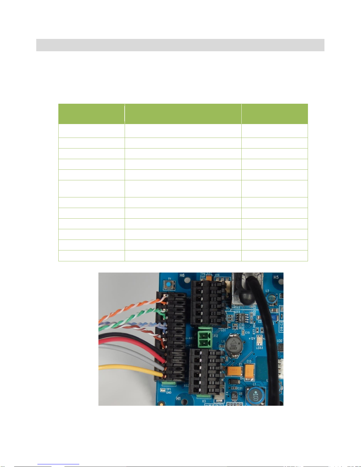
a. Connect the system cable to the I/O Board according to the table below
Drive5 X4 connector
pin number
Wire color
Signal
1
White/orange in Cat5e cable
Ethernet A+
2
Orange in Cat5e cable
Ethernet A-
3
White/green in Cat5e cable
Ethernet B+
4
Green in Cat5e cable
Ethernet B-
5
White/blue in Cat5e cable
Ethernet C+
6
Blue in Cat5e cable
Ethernet C-
7
White/brown in Cat5e cable
Ethernet D+
8
Brown in Cat5e cable
Ethernet D-
9
Black wire
GND
10
Red wire
+24V dc
11
Grey
Vinit+
12
Yellow
Vinit-
Figure 1. System cable connected to I/O Board
Page 6
― 6 ―
b. Connect the other end of the cable to power (Black/Red) (24VDC)
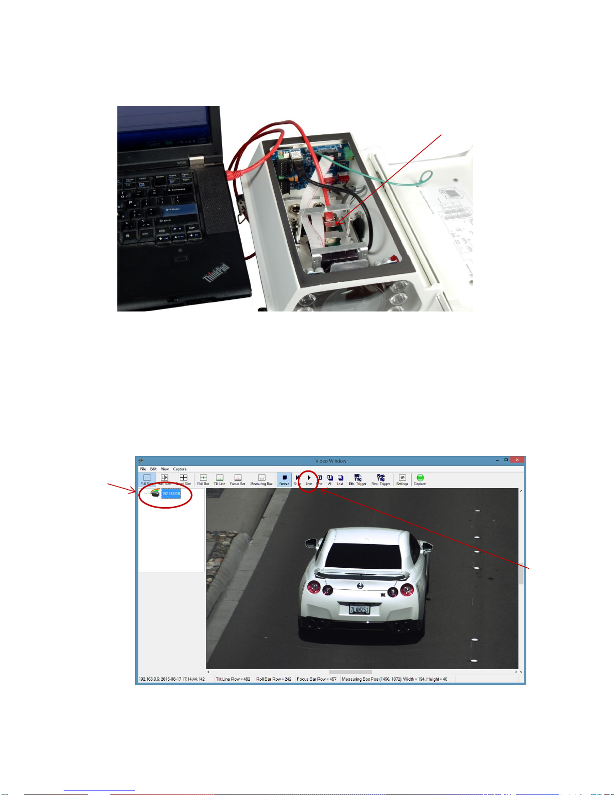
c. Remove the internal cable from the camera’s RJ45 connector and connect the laptop
Ethernet adapter directly to the camera’s RJ45 connector.
Figure 2. Connect laptop to camera’s RJ45 connector
d. Apply power (24V DC). The I/O Board has 4 LEDs to indicate status. See Appendix A for the
locations of these LEDs and see Appendix B for troubleshooting information.
e. Configure your network adapter for a static IP of 10.0.0.xx, with xx being anything but 65.
This will put the computer on the same subnet as the camera (as configured at the factory,
the camera is set to 10.0.0.65). See Figure 16 for an example.
f. Start EN Setup on laptop. Wait approximately 1 minute for the camera to boot up.
g. Click on the Video button, then on the camera in the left pane.
Figure 3. EN Setup Video Window
h. Click on the “Live” button to start image acquisition.
Disconnect internal Drive5
cable and connect laptop
to here as shown
Click on camera
“Live” button
Page 7
― 7 ―
i. Using the pan, tilt and roll adjustments on the mount, aim the housing at the target.
j. Loosen the lens adjustment thumbscrews.
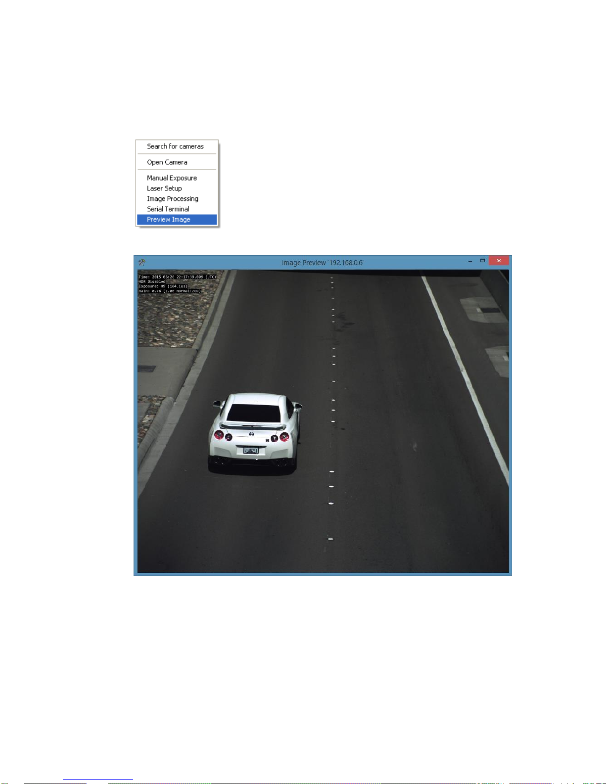
k. Adjust the focus, and if necessary the zoom adjustments on the lens to achieve the field of
view you desire. Right click on the image and select “Preview Image” to get a view of the
entire image.
l. Readjust the pan, tilt, roll, zoom and focus until satisfied with the field of view and focus.
Figure 4. Properly adjusted image (dual-lane setup)
m. Tighten lens adjustment thumbscrews.
n. Lock down the pan, tilt and roll adjustments.
o. Remove Ethernet cable from the camera RJ45 and reinstall the cable from the I/O Board
RJ45 into the camera RJ45.
p. Close and latch the lid.
Page 8
― 8 ―
Drive5 System Installation Manual
1 Introduction
1.1 Document overview
This Installation Manual details steps for deployment of the Drive5 traffic camera system, as well as
maintenance and troubleshooting information. The system consists of a high performance camera,
LED illumination, weatherproof long-lasting housing, and I/O Board
JAI strongly recommends that the installer reads this manual thoroughly, in order to obtain sufficient
knowledge about the Drive5 equipment, before initiating the actual installation.
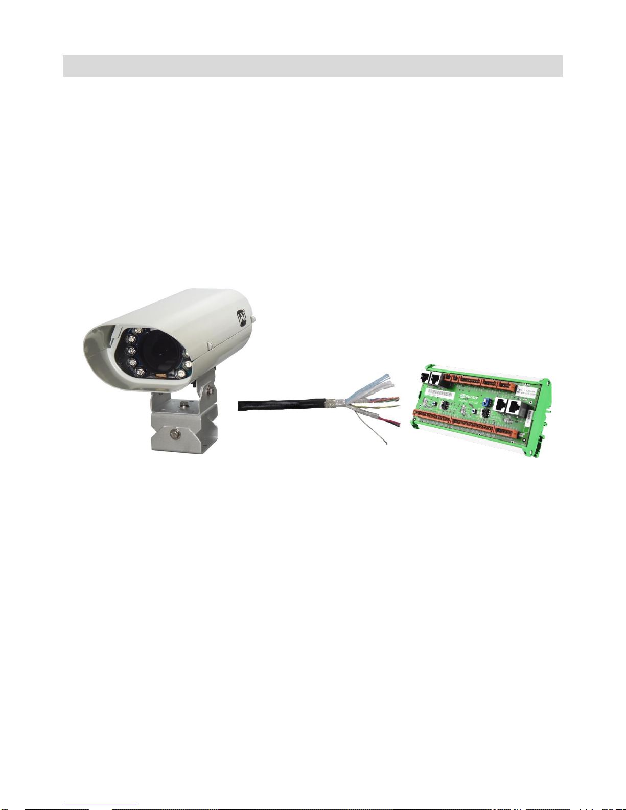
1.2 Product overview and system hardware components
Figure 5. Drive5 components overview (not to scale)
The Drive5 uses a state-of-the-art 5.3-megapixel camera system with a 1-inch format CMOS image
sensor that freezes the motion of a rapidly moving vehicle at high resolution. The system includes a
fixed focal length lens; an on-axis illuminator; and a weatherproof housing with sun shield, heater
resistors, I/O Board, and a pan-tilt-roll mounting bracket.
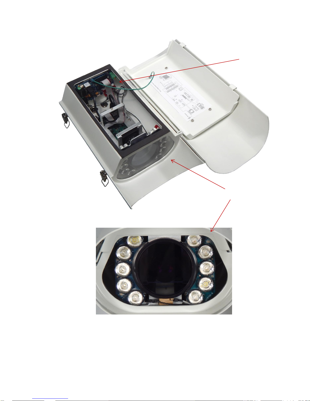
The Drive5 features an embedded JAI trigger/light sensor for image triggering and image contrast
control. It also features an embedded LED Ring Light illuminator (infrared, white or blue) for
independent 24/7 operation and excellent license plate contrast (see Figure 6).
The Drive5 system is Ethernet based with a built-in processor using an embedded Linux O/S for
various operations, such as data transfer to the back office, frame storage, JPEG compression, and
so on.
Installing the Drive5 involves connecting a system cable (sold separately) to the I/O Board in the
Drive5 system (see Quick Start Guide or Section 3 for instructions). The other end of the system
cable connects to your power source, your network, and your Vinit trigger input. JAI provides, and
strongly recommends, the use of a J-panel board (sold separately) to make these connections. The JPanel is a DIN-rail-mounted PCB (printed circuit board) equipped with various interface terminals for
interconnection. Each J-panel can support up to two Drive5 systems.
Drive5 System
System Cable
(sold separately)
J-Panel
(sold separately)
Page 9
― 9 ―
Figure 6. Drive5 system with I/O Board and LED Ring Light
I/O Board
LED Ring Light
Page 10
― 10 ―
2 Preparing for installation
2.3 Installation preparation
To prepare for installation, consider the fundamental requirements for an effective deployment of the
Vehicle Imaging Subsystem. There are two basic configurations: overhead (over the lane) or side fire
(beside the lane). Figure 7 depicts a typical overhead configuration. Figure 9 depicts a typical side fire
configuration.
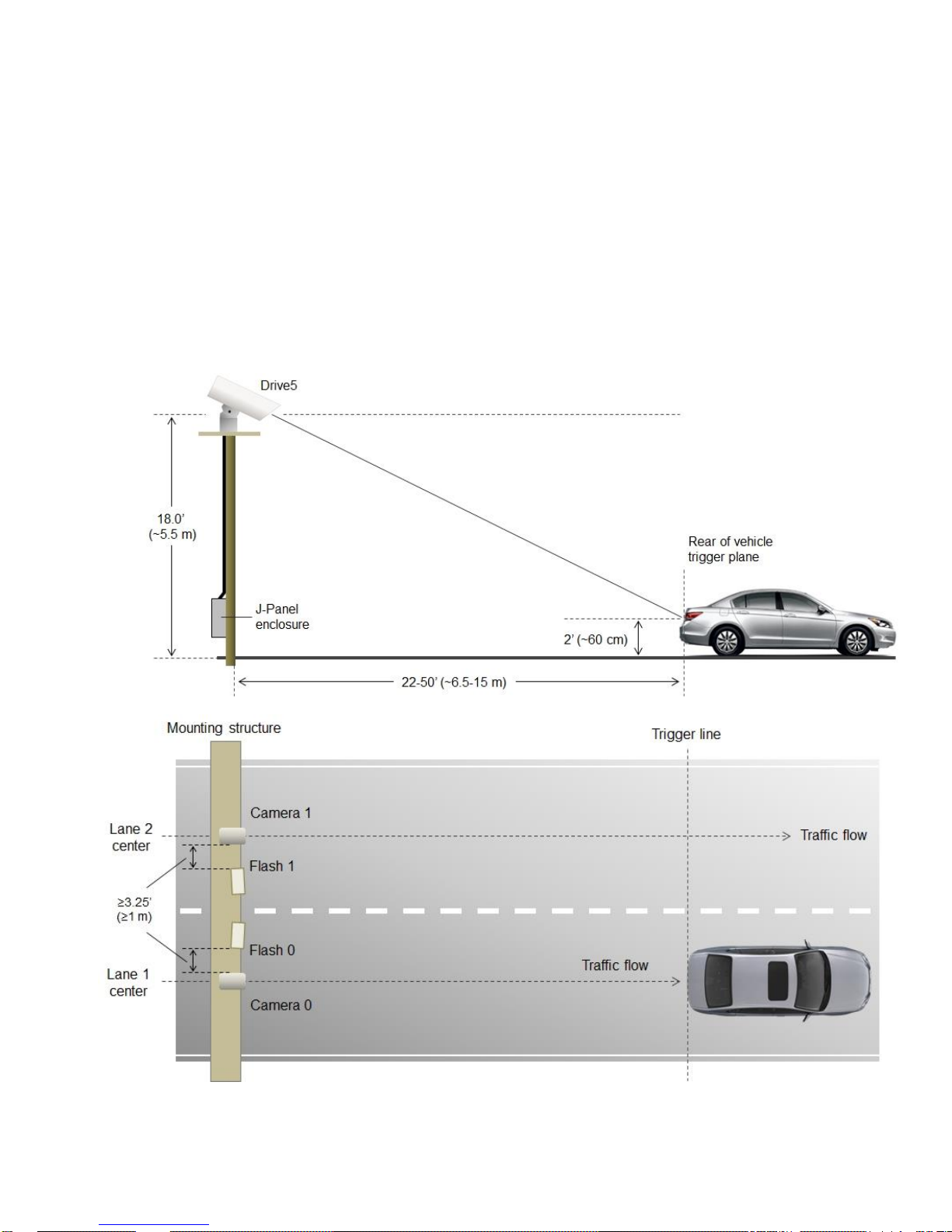
2.4 Overhead positioning
Over lane camera mounting is always employed when the road width being monitored contains three
or more lanes of traffic, when a convenient overhead structure is already in place, or when preventing
vandalism is a paramount concern. Each Drive5 system can be configured to cover a single lane or
two lanes, depending on type of plate and standard lane sizes.
Figure 7. Typical overhead site layout – one Drive5 per lane (with optional external flash units)
Page 11
― 11 ―
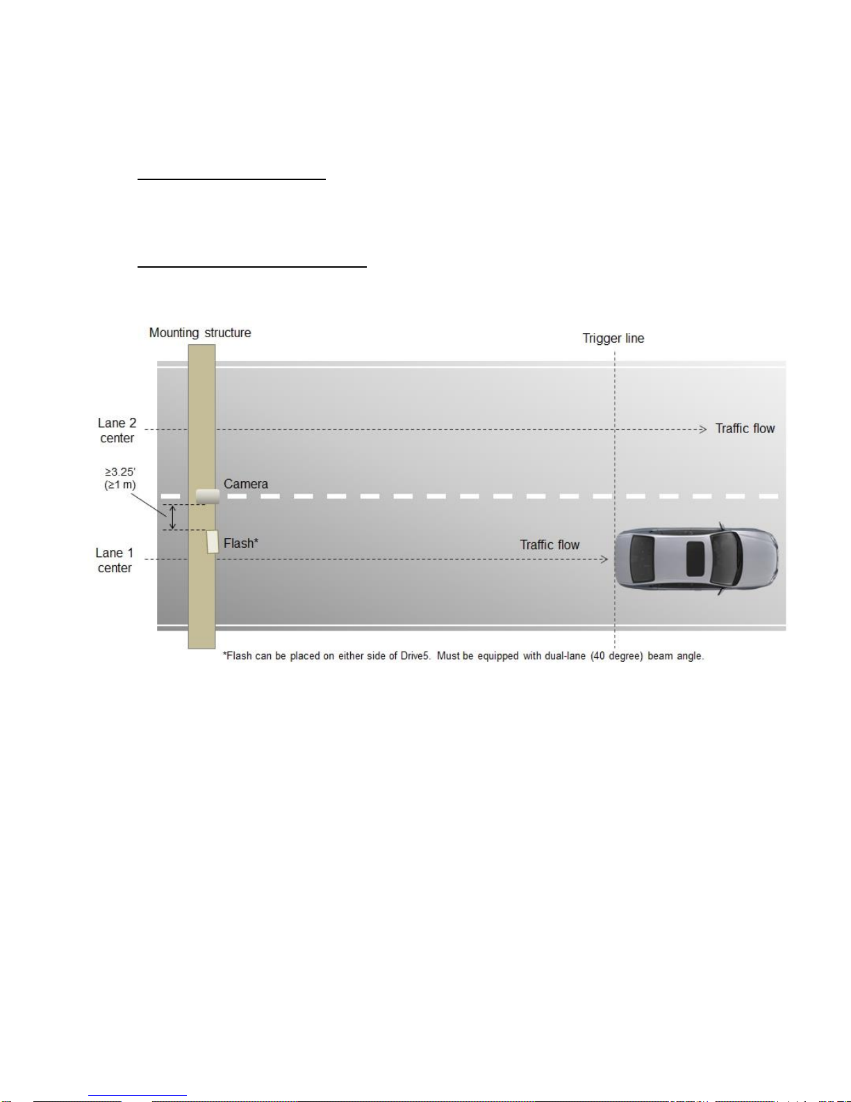
Single lane or dual lane considerations
Figure 7 shows a typical single lane configuration. However, with the Drive5’s higher 5-megapixel
resolution and 1-inch sensor format, it can cover up to two lanes of traffic. The Drive5’s lens is
adjusted during installation to create the following conditions:
Standard for US style of plates: 135 pixels across a 1 foot wide license plate placed 2 feet above the
ground level at the nominal trigger position (ground loop, laser, etc.). With typical US lane coverage
(14’), the Drive5 will yield ~180 pixels/plate. If maintaining 135 pixels per plate, the lane coverage is
now 18’.
Standard for European style of plates: 140 pixels across a 50 cm wide license plate placed 60 cm
above the ground level at the nominal trigger position (ground loop, etc.). The coverage is now up to
9 meters, which can definitely cover two lanes (see Figure 8 below).
Figure 8. Typical overhead site layout – dual-lane coverage (with optional external flash unit)
Camera tilt considerations
The requirement to freeze the motion of high-speed vehicles limits how steep or shallow the tilt angle
of the camera may be. For example, it is important to prevent the horizon from appearing in the
image, and thereby allowing the sun to blind the camera. For over lane installations, a camera tilt
between 20° to 30° is recommended, with 25° being considered the optimal angle. This angle of tilt is
the best compromise between minimizing visibility blockages caused by closely spaced vehicles and
maximizing plate visibility for plate mounts that are slightly recessed or tilted downwards.
Asynchronous triggering considerations
An embedded vehicle detector is employed to cause the camera to capture an image at the precise
moment the vehicle is in the best position to image both the vehicle and its license plate. If an
external triggering device is used (i.e., ground loop or laser) the delay between the time the vehicle
passes the trigger position on the road and when the trigger signal actually reaches the Drive5 must
be kept to a minimum to prevent high-speed vehicles from moving out of the area viewed by the
camera before the image is snapped.
Page 12
― 12 ―
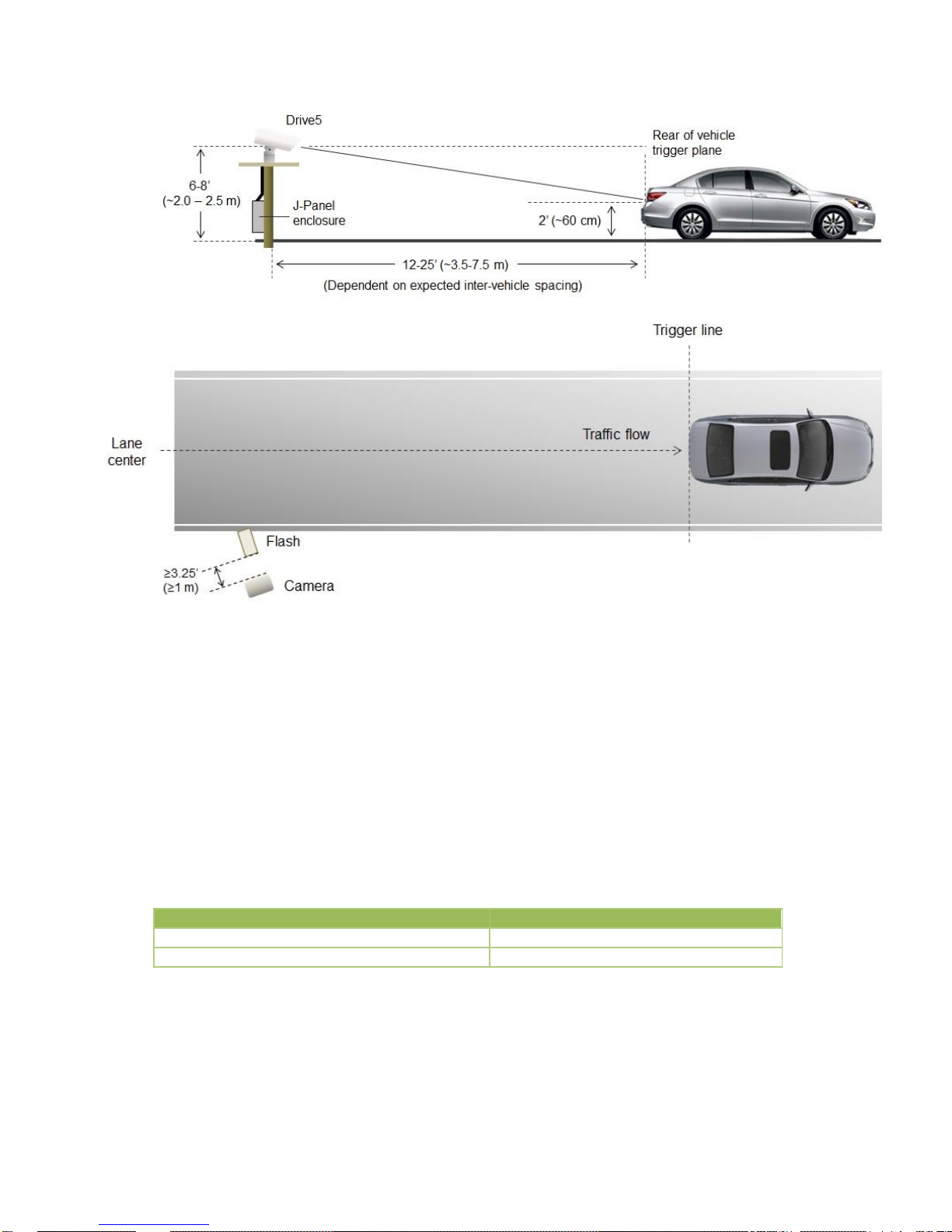
2.5 Side of road installation
Figure 9. Typical side-fire road installation – one lane per Drive5 system (with optional external flash)
2.6 Flash considerations
The Drive5 system comes equipped with a built-in on-axis LED illuminator (LED Ring Light) designed
to capture nighttime images of retro-reflective number plates, or to enhance the brightness of daytime
plate images in shade conditions or under cloudy or foggy skies.
For illumination of both plates and vehicles under nighttime conditions, the Drive5 system can be
integrated with the optional TNL-50 external flash unit. By positioning this high-powered flash unit a
short distance away from the Drive5, proper exposure of the overall scene can be achieved without
overexposing the plate. Table 1 below shows the minimum distance from Drive5 to flash/light unit
(distance normal from camera-license plate axis):
Drive 5
Unit to Flash Spacing (minimum)
Approximate distance in feet
3.25
Approximate distance in meters
1.0
Table 1 Minimum spacing distance between Drive5 and flash/light unit
If the flash is positioned closer to the camera, reflections from retro-reflective license plates will likely
cause overexposure. Tests have shown that positioning the flash up to two meters (6.5 feet) away
from the Drive5 will generally produce good results.
Page 13

― 13 ―
If the distance from the camera to the trigger line is further than 50 feet, then the spacing between
flash and camera will have to be increased to avoid increasing the retro-reflectivity effect, and the
intensity of the flash will have to be increased or else the background will not be visible in the image
even when retro-reflective license plates are close to saturation.
Page 14

― 14 ―
3 Installing the Drive5 system
The individual components of the system are electrically linked together as shown in Appendix A,
“Drive5 I/O Board Connection Overview.”
3.1 Drive5 power requirements
The Drive5 system requires a 24V DC power supply. The table below shows the power consumption
for two Drive5 units connected to a power supply via the recommended J-Panel board (4.2 * 24 =
100.8 W, steady state). For direct connection of a single unit to a 24V DC power supply, inrush
current is 3.5 A, steady state current is 2.0 A.
System Components
Current (Steady State)
Current (Inrush)
Drive5 System #0 (with heater on)
2.0 A
3.5 A
Drive5 System #1 (with heater on)
2.0 A
3.5 A
J-Panel (VJP-300)
0.2 A
1.5 A
Total
4.2 A
6.5 A*
* When connected using J-Panel, inrush current is limited to 6.5 A
Table 2 Drive5 power requirements
3.2 Installing the Drive5 system
Step 1: Attach Drive5, with mount, to the mounting structure. The hole pattern is shown in Figure 10.
Figure 10. Drive5 mount dimensions
Figure 11. Drive5 pan-tilt-roll base
Mounting holes
Page 15

― 15 ―
Step 2: Route the Drive5 end of the system cable in accordance with local electrical code
requirements.
Step 3: The jacket is removed from the cable on the camera end a distance of 7” (~18cm) (1). A thin
wire is attached around the end of the cable to keep the braid in place (2). The cord grip sealing nut is
mounted on the cable (3). See Figure 12.
Figure 12. Drive5 system cabling as it appears after jacket is removed
Step 4: Route cable through enclosure cord grip. Braid/foil shield should be aligned with the cord grip
nut inside enclosure to ensure proper shield connection with EMI cord grip. See Figure 13.
Figure 13. Cable is routed properly to ensure proper shield connection
Step 5: Hand-tighten the sealing nut as far as possible. Hold the body hex stationary with a 24 mm
wrench. Using a second 24 mm wrench, tighten the sealing nut until the cable is securely held in
place. Torque to approximately 35 in. lbs. (3.9 Nm) Note: there is no standard SAE wrench size that
will properly fit the hex nuts. You must use either a 24 mm metric wrench or an adjustable wrench.
Step 6: Move the thin wire 2 inches (5 cm) away from the cable end and fold the braid back over the
thin wire. Use a cable strip to keep the braid in place. Remove foils and fillers from the cable end.
Separate and strip the wires. The 2 pairs of multicore wire can be fitted with bootlace ferrules to keep
the cores in place. Connect wires to terminal block X4 on the Drive5 I/O Board in accordance with
wiring diagram on enclosures inner lid (see Appendix A and Figures 14 and 15 on the following
page). Plug terminal block back to X4 position on Drive5 I/O Board. Close and secure enclosure lid
with 2 latches.
(3)
(1)
(2)
Outer
braid
Grounding
tongues
Page 16

― 16 ―
Figure 14. Drive5 system cable
Figure 15. Wires are inserted in Drive5 I/O Board X4 connector
Page 17

― 17 ―
4 System setup
This section provides a generic procedure for aligning one or more Drive5 system and associated
equipment at a site.
The example installation process described in this section assumes that:
The cameras are being mounted on an overhead structure directly over the lane(s) being
observed. The process for aligning a camera mounted at the side of a lane is essentially the
same as aligning a single camera mounted directly overhead.
The unit employs vehicle detection that will automatically trigger the camera (see Section
4.7). To determine where the vehicle will trigger, the EN Setup program can be made to
display a trigger area region. This function is enabled by clicking on Debug Output Mask in
Section 1 of the EN Setup camera properties and selecting ”On Image Graphics” as shown
below.
This region shows the area where the camera will detect a moving vehicle. This will give the
approximate trigger line. Since the unit is using motion detection technology, the trigger line
will vary a little depending on the speed of the vehicle.
If the installation utilizes other modes for triggering, the unit can also accept a discrete TTL or
Ethernet signal to the Drive5 system whenever the back (or front) of a vehicle crosses a fixed
line across the road. This line is referred to as the “trigger line” in this document.
The installer should be familiar with using the EN Setup program supplied by JAI. Make sure
you are using the latest version by checking at www.jai.com. Please refer to the EN Setup
Program User’s Guide if you are unfamiliar with this software. JAI offers engineering support
Page 18

― 18 ―
and software tools to help select the optimum camera and trigger locations to meet your
specific project needs.
System settings are set to factory default value. This can be done by pressing the Load
Factory Defaults button on the tool bar in the Properties window.
4.1 Pre-alignment checklist
Validate targeted lane coverage and lane overlap (if any)
Make sure you have an appropriate laptop computer with the JAI EN Setup program
installed.
The setup computer needs to have an Ethernet network adapter installed (preferably 1
Gigabit Ethernet Adapter) and the TCP/IP network configured with the correct IP-address,
subnet-mask and default-gateway.
The setup computer and the cameras need to be on the same subnet. The cameras are
shipped with the standard IP-address “10.0.0.65” and subnet-address “255.255.255.0”, and
the setup computer needs to be assigned an IP-address “10.0.0.xx” in order to automatically
discover the cameras using the EN Setup program (NB! “xx” must not be “65”).
Figure 16. Assigning IP addresses
All cameras have to be given unique IP-addresses before the alignment begins. This is done
using the EN Setup application.
Page 19

― 19 ―
Confirm all Drive5 components and cables are properly connected.
Ensure network meets minimal system requirements.
4.2 Select a suitable vehicle, license plate, and plate stand for the setup
To accurately set up the Vehicle Imaging Subsystem, the system installers need access to:
1. A vehicle that can be temporarily parked on the road
2. A plate that is:
Typical in size and color for the site
Clean, flat and in “like new” condition
4.3 Connect the setup computer to the camera
Position the setup computer next to the camera being aligned. Make sure that nothing interferes with
the camera’s view of the road.
Connect the setup computer’s network adapter directly to the camera. Configure your network
adapter for a static IP of 10.0.0.xx, with xx being anything but 65. This will put the computer on the
same subnet as the camera (as configured at the factory, the camera is set to 10.0.0.65).
Figure 17. Example of direct connection to the camera
Once the setup computer is connected, you can apply power to the Drive5 (24V DC). The I/O Board
has 4 LEDs to indicate the status of the heaters, power supply, and microcontroller (I/O Board setup
parameters). Appendix A shows the locations of these LEDs. Appendix B contains an explanation of
the meaning of the lights and the colors that indicate proper operation.
Disconnect internal camera
cable from here and plug in
patch cable from setup
computer.
Page 20

― 20 ―
4.4 Drive and park the setup vehicle correctly
Park the vehicle on the trigger line. Make sure that the vehicle is parked aimed in the same direction
as the average driver would point their car if they were driving through this section of roadway.
4.5 Perform initial lens adjustment and camera aiming
1. Loosen the roll, pan, and tilt bolts on the JAI camera mounting head until each axis can be easily
adjusted by hand but any particular setting will stay in place after you let go. (Slight amount of
friction)
2. Power on the setup computer and then start the EN Setup program. Wait approximately 1 minute
for the camera to boot up.
3. Press the “Video Window” button to open the Video Window and then select the camera for
adjustment from the tree-view on the left side of the window. Press the “Live” button in the toolbar
to start rapid image acquisition. “Live” mode disables the flash, so at night use the “Rep. Trigger”
instead.
4. Using the pan, tilt and roll adjustments on the mount, aim the housing at the target vehicle. Adjust
the focus adjustment on the lens to achieve the field of view you desire.
5. Right click on the image and select the “Preview Image” to get a view of the entire image.
Readjust the pan, tilt, roll and focus until satisfied with the field of view.
6. (Optional) Use the measuring box to measure the size of the license plate. Ensure it meets your
requirements.
7. Lock down all adjustments when done. Double check your field of view to make sure nothing
moved while locking it down.
4.6 LED Ring Light embedded illuminator setup
The LED Ring Light embedded illuminator is primarily used by the Drive5 to provide sufficient light for
the built-in Vehicle Detector (VD) trigger system, so the camera will be able to trigger during night
time when the ambient light is insufficient to light up the vehicles. The LED Ring Light is also utilized
during the daytime to make the retro-reflective license plates stand out when they are in shadow
condition. The brighter license plates will enhance the contrast and the readability leading to higher
ALPR performance.
Pan control
Tilt controls
Roll controls
Page 21

― 21 ―
The LED Ring Light illuminator has two usage modes: Traffic Safety and Triggered Flash Mode.
Traffic Safety (Continuous Light):
Traffic Safety mode is designed to minimize the level of driver distraction caused by periodic flashes
emanating from the LED Ring Light. In this mode, the LED Ring Light is constantly on at a low level of
brightness specified by the user in the LED Ring Light Settings window. When a passing vehicle
triggers the camera system, the Drive5 will produce a high intensity flash sufficient for color image
capture. But because of the continuous lighting, the flash will be much less noticeable to the driver’s
already partially adjusted eyes. To enable Traffic Safety mode and set a continuous light intensity
level, right click on the camera symbol in the Properties window and select Advanced Settings –>
Configure LED Ring-Light Settings.
A dialog box will open and the settings for the LED Ring Light can be controlled from here:
Figure 18. LED Ring Light Settings dialog box
When selecting light intensity settings, those settings are automatically saved in the I/O Board and
become the default settings next time the system is powered on. When selecting a “custom” setting,
the [Set] button must be selected for the value to take effect.
Triggered Flash:
When the camera captures an image, the LED Ring Light can flash at a different light level. The LED
Ring-Light Mode and LED Ring-Light Intensity settings affect this usage.
LED Ring-Light Mode - There are two options available (see Figure 19).
Page 22

― 22 ―
Figure 19. LED Ring-Light selections in EN Setup
- Manual Light Level: the light level is manually set using the LED Ring-Light Intensity setting.
Values range from 0 (no flash) to 100 (maximum intensity). The selected light level will be
used regardless of ambient light conditions.
- Auto Light Level: light level can be controlled automatically with the help of ALC. The “LED
Ring-Light Auto Intensity” settings let you fine tune the light level for various ambient light
conditions (see Figure 20).
Note: additional settings in this camera properties section are for use with an external flash unit such
as JAI’s TNL-50. See the TNL-50 documentation for an explanation of the settings.
Figure 20. LED Ring Light flash mode and auto intensity settings in EN Setup
When Auto Light Level is selected the following settings take effect:
- LED Ring-Light Auto Intensity Minimum: the lowest light intensity level to which the ALC
(Auto Level Control) will set the LED Ring Light flash intensity.
Page 23

― 23 ―
- LED Ring-Light Auto Intensity Maximum: the highest light level the ALC will set the LED Ring
Light flash intensity.
- LED Ring-Light Auto Intensity Knee Point 1 and Knee Point 2: have units in Light Sensor (LS
A-Side) from ALC. Intensity is equal to:
If LS value < Knee Point 1 then intensity equals Intensity Minimum
If LS value > Knee Point 2 then intensity equals Intensity Maximum
The operation of the LED Ring Light in Auto Light Level mode is represented in the graph below.
Figure 21. Auto Light Level operating principle
4.7 Automatic triggering and light sensing configuration
This section describes the parameters to configure when setting up for automatic triggering (Vehicle
Detector trigger) and light sensing (ALC).
Vehicle Detector Trigger settings
Select “Vehicle Detector” within “External Trigger Source” to enable the Vehicle Detector Trigger.
The system will automatically detect moving vehicles in up to two separate lanes. Note that the traffic
in both lanes must be moving in the same direction.
The Vehicle Detector uses a 200-line-high detection area that covers the full width of the image. This
detection area is internally split into 9 horizontal detection grids. Each grid can be individually enabled
or disabled. When used in single lane mode, all 9 are used. When in dual-lane mode, four grids are
used per lane and the center grid is normally disabled.
The Vehicle Detector properties are located in the EN Setup camera properties Section 12 - “Vehicle
Detector.”
Page 24

― 24 ―
Figure 22. Vehicle Detector settings
The following paragraphs provide short descriptions of the Vehicle Detector parameters:
Shadow Suppression Mode – Disable/Enable shadow suppression. Enabling this feature can help
reduce false triggers caused by shadows. During certain times of day when a vehicle shadow is
sufficiently dark compared to the road surface, it could be mistaken as a vehicle by the Vehicle
Detector. The shadow can be from a car in the adjacent lane, or a long shadow cast in front of or
behind the vehicle. Be advised, however, that the use of shadow suppression mode also increases
the chances of missing vehicles. This is especially true when the road surface is light in color, causing
Shadow Suppression Mode to incorrectly identify dark vehicles as shadows. In many cases, it may be
wiser to tolerate some false triggers rather than to miss some legitimate ones.
Trigger Line - This determines the location of a “virtual trigger line” which in fact is the center line of a
200 lines high “Vehicle Detection Area” inside the image. It is specified as the line number of the
center line measured from the top of the image and down to the center line of the “Vehicle Detection
Area”. The range is from 350 to 1702 (default).
Retrigger Delay - This setting determines the minimum number of frames between two consecutive
triggers. The allowable range is 0 to 63. The actual time can be calculated as the number of frames
multiplied by the frame-rate selected in the Trigger Sync mode setting. If multiple triggers occur within
this time then only the first trigger will be accepted. The purpose for this setting is to minimize the
number of “multi triggers” where the same vehicle generates multiple triggers but only a single image
is needed to identify the vehicle.
Lane Empty – This setting is essential to the “Rear Shot” Lane Direction mode (explained below).
This specifies the maximum number of “empty” frames the triggering system is allowed to wait in
order to make sure that the vehicle has left the detection area. Valid range is between 1 and 11. If this
value is too low then a lot of multi-triggers will be generated. If it is too high then it limits the ability to
detect tail-gating vehicles (in case the tail-gating vehicle is closer to the vehicle in front than the
number of frames specified). Default value is 11 and it is recommended to keep this maximum value
whenever possible since this will reduce the amount of double-triggers on trucks with trailers.
However, for high-speed traffic installations the value might need to be lowered (or frame-rate
increased) to avoid missing tail-gating vehicles.
Lane Configuration - This selection has the choice of Single Lane and Dual Lane. In Single Lane, the
Vehicle Detector algorithm uses the whole Vehicle Detection Area to detect a vehicle. In Dual lane,
the image is divided in half and each half is used to detect vehicles. Thus, if a vehicle happens to be
crossing between lanes, there may be an instance, where the same vehicle may be triggered in both
lanes.
Lane Direction – This selects the way the Vehicle Detector triggers are generated. In “Rear Shot”
mode the vehicles will be travelling away from the camera and the triggers are generated when the
Page 25

― 25 ―
vehicle leaves the detection area. In “Front Shot” mode the vehicles will be travelling towards the
camera and the triggers are then generated when vehicles enter the detection area.
Detection Grid – It is possible to enable/disable the Vehicle Detection in each of the 9 grids of the
detection area. It is recommended to disable the middle (Grid 5) in dual-lane configuration. This will
minimize the number of multi-triggers that might occur if the passing vehicles get too close to the
middle detection zone (which is shared between both left and right lane).
Visualization helper for Vehicle Detector and ALC setup
The camera can superimpose the Vehicle Detection Area and Auto Level Control (ALC) Area onto the
image to help during trigger line setup. To enable visualization enable them in “Debug Output Mask”:
*
Select “On Image Graphics” (Vehicle Detector): to show Vehicle Detection Area
Select “On Image ALC Area”: to show ALC Area
Figure 23. Vehicle Detector and ALC visualization settings
* Be sure to disable the graphics when finished. They appear in the final image!
Figure 24. The on-image visualization helper as displayed in the image
The visualization elements consist of:
Vehicle Detection Area (green boxes):
Each box represents 1 detection grid. There are 2 groups: left lane and right lane.
Trigger Line: when in “Live” view mode, aim the camera so that the plates for each lane are
at this Trigger Line and in their respective side.
A trigger happens as a vehicle drives past the Trigger Line and comes out of the detection
area.
The middle blue vertical line should be on top of and line up with the center of the lane (single
lane configuration) or with the lane divider (dual lane configuration).
Auto Level Control (ALC) Area (red & purple box):
The ALC area should be configured as close to the license plate area as possible to ensure
accurate reading of the current lighting conditions.
Page 26

― 26 ―
Shadows cast onto the plate may not be cast on different parts of the field of view making the
plate seem darker in the resulting image.
Auto Level Control (ALC) settings
The Drive5 supports real-time light sensing using the internal Auto Level Control (ALC) light sensing
functionality for exposure control of the camera. The ALC settings are found in the ADR Control
section of the EN Setup camera properties (Section 5). ADR Control is set to ALC by default and
should not be changed by the user. The specific ALC control settings are highlighted in Figure 25 and
are explained in the paragraphs that follow.
Note that the ADR Shutter Max setting is also used by ALC. It specifies the longest (slowest)
allowable shutter speed for auto exposure purposes. Recommended values range from 0 (30 µs) to
855 (1000 µs). Other ADR-related settings are for use with external light sensing equipment, which is
not supported by Drive5.
The settings specific to the ALC mode of operation are marked in the following figure.
Figure 25. ALC settings
Camera ADR Control – The mode has to be set to ALC in order to enable the internal light sensing.
ADR Shutter Max – See explanation on previous page.
ALC Target Value – This is the “set-point” for the closed-loop control of the camera exposure. This
value represents the target average value for the ALC Region of Interest (ROI). It is a 10-bit value
which is then four times higher than the average value measured in the output images from the
Drive5 (which are all in 8-bit resolution). So if the ALC Target Value is set to 200 for instance, then
the average intensity of the ALC ROI in the output images will be around (200/4)=50. The ALC Target
Value should be kept between 150 - 250 in order to insure a proper brightness and contrast of the
resulting images from the camera. By keeping the value low there will be a larger “margin” so that
over-exposed license plates can be avoided.
ALC Damping Factor – This setting controls the speed of the closed-loop control of the camera
exposure. It represents the percentage of change allowed by the control loop for each individual
frame. A low value (10-25) makes the ALC more stable and will give less fluctuation in the exposure.
A high value (75-90) will make the ALC very responsive but at the same time the brightness of the
output images will vary a lot depending on the brightness of the passing vehicles. It is recommended
to keep the ALC Damping Factor as low as 25% or even lower in order to prioritize stability over
responsiveness of the ALC.
Page 27

― 27 ―
ALC Maximum Gain Level – This sets the maximum amount of gain the ALC will use to adjust the
camera exposure. The value is a normalized number between 0% and 100% gain. This will
essentially limit the maximum worst-case gain and hence limit the amount of noise in the images
when it becomes dark.
ALC ROI top/bottom/left/right – these four settings specify the area from which the ALC calculates the
average measurements for the control loop. This area should be selected so it covers the background
(asphalt or concrete road) area where the vehicles will be located when the images are captured.
This will in most cases be close to the Vehicle Detection area. If the Vehicle Detector is in Rear Shot
mode then the ALC area should be put a bit higher than the detection area (since the vehicles are
captured when they are leaving the detection area). If the Vehicle Detector trigger line is being moved
up or down then the ALC ROI should be moved the same amount in the same direction.
4.8 High dynamic range (HDR) settings
The imaging sensor used in the Drive5 supports multi-slope integration. This makes it possible to
increase the dynamic range of the sensor, and helps avoid over-exposed license plates in challenging
light scenarios where the ALC control is unable to correctly assess the brightness of the license plate
and the vehicles when the images are captured. The challenging light scenarios are often caused by
shadows being cast onto the scene in a way where the ALC measures the average of the road
surface in shadow – but where the vehicle will be in the direct sun and thereby inadvertently cause
the vehicle to become over-exposed!
However, be aware that multi-slope HDR reduces the contrast in the brighter parts of the image and
also impacts the Drive5’s ability to properly process the color of the scene. Images will tend to have a
pinkish hue in the brightest areas, which will be further exaggerated if white balancing is used.
Therefore, it is recommended that the High dynamic range remains disabled (default setting) unless
required by the lighting conditions. Furthermore, when enabled, users should set the controls to apply
only as much additional dynamic range to the image as needed to resolve the exposure issue.
The HDR settings are adjusted directly in EN Setup camera properties using Section 10 – “High
Dynamic Range Control.”
Figure 26. HDR settings in EN Setup
HDR Enable - Selects if the multi-slope integration is enabled or disabled. Default is Disable.
HDR Slope 1/2 Reset percentage - Select the multi-slope reset time for the second and third slope of
the multi-slope integration of the sensor. The reset time is set as a percentage of the total exposure
time so it will automatically be adjusted when the exposure time is changed by the ALC. The higher
the value, the later the reset, which in turn increases the dynamic range.
The multi-slope integration will change the sensor’s response to the light as shown in the following
graphs:
Page 28

― 28 ―
Figure 27. Example of different multi-slope integration settings
If the HDR functionality is switched off then the sensor will have a linear response to the light. If HDR
is enabled then the slope of the response curve will get a “knee-point”. When the light level gets
above this level then the sensor gets less sensitive to the light, (less steep curve) and will be able to
image what would otherwise result in an over saturated/clipped image.
Multi-slope integration will also result in a “compression” of response of the sensor above the kneepoint, and the “contrast” of the bright part of the image will be lower when the HDR level is increased.
Another side-effect is also that the images will get a “pinkish tint”, so that the color fidelity of the
brighter areas of the image will be lower.
Figure 27 above shows two settings:
- Reset time at 70%/85% of the exposure time: This settings makes the sensor capable of
coping with approximately twice the amount of light compared to the linear response (HDR
OFF)
0 200 400 600 800 1000 1200 1400 1600 1800
0
50
100
150
200
250
300
Light level (fL)
Mean
OFF
ON, Level 6, Reset 70%/85%
ON, Level 6, Reset 80%/90%
0 200 400 600 800 1000 1200 1400 1600 1800
0
50
100
150
200
250
300
Light level (fL)
Mean
OFF
ON, Level 6, Reset 70%/85%
ON, Level 6, Reset 80%/90%
Page 29

― 29 ―
- Reset time at 80%/90% of the exposure time: This settings makes the sensor capable of
coping with approximately four times the amount of light compared to the linear response
(HDR OFF)
It is recommended to use as little HDR as possible so that compression and lower contrast in the
images is minimized.
4.9 Time synchronization settings
Most ITS systems require that all cameras are time synchronized – both with the back-office as well
as with each other. The Drive5 supports time synchronization using the standard Network Time
Protocol (NTP) where one or more designated NTP Servers provide the time for the whole system.
The NTP Time Synchronization is configured directly using EN Setup in Section 14 – “Time
Synchronization.”
Figure 28. Time synchronization settings in EN Setup
Before enabling the NTP Client all configuration parameters have to be set up, or else it will require a
restart of the NTP Client in order to make the parameters effective.
The following parameters need to be configured:
NTP Client Control – Enable or Disable the NTP client in the camera.
NTP-Server 1/2/3 IP-address – These parameters specify which NTP Server(s) on the network that
the NTP-Client will use for the time synchronization. The first IP-address in the list will be considered
the preferred server.
NTP Max estimated Error – Specifies the maximum estimated error allowed (in microseconds) before
a ERROR_NTP_TIME error telegram will be generated when an image is captured. This is typically
used in systems where there is a strict requirement to the synchronization accuracy of all cameras
(like for instance Section Control systems).
Real Time Clock – Displays current NTP adjusted date and time. This will be used for all time stamps
on images and messages.
NTP Mode – This controls the NTP-Client mode of operation. Three modes are available: a) “Default”,
b) “Burst” and c) “Burst + Min/Max Poll intervals”. “Default” mode will use default configuration
parameters when NTP Client control is enabled. “Burst” mode will speed up the initial communication
Page 30

― 30 ―
to/from the NTP Server and thereby help the NTP Client start/restart faster. “Burst + Min/Max Poll
intervals” mode will both speed up initial communication as well as set the minimum and maximum
poll interval for communication between the NTP Server and the NTP Client. This typically means that
the minimum and maximum poll intervals are changed to a lower value than that of the “Default”
mode, thereby making the NTP Client more responsive and more accurate, especially in cases where
the NTP Server is not a high-end dedicated time server, but instead is a service running on a
standard PC on the network.
NTP Minimum/Maximum Poll interval – These two settings specify the poll interval range used by the
NTP Client. The values are defined in seconds as a power of two so a minimum value of 4 translates
to 24 seconds = 16 seconds. A value of 6 translates into 26 seconds = 64 seconds. The minimum
value is the poll interval being used whenever the NTP Client starts up. It will then gradually increase
the poll interval to the maximum value and this maximum value will be used when the time
synchronization is in a steady state.
It is recommended to use the “Burst + Min/Max Poll Interval” mode when a standard PC is being
utilized as the NTP Server on the network.
The following three items are status readouts only and are not configurable by the user:
NTP estimated error (us) - This status value shows the estimated accuracy of the camera’s time
value relative to the UTC. The estimate is based on the NTP protocol’s ability to measure the
communication latency and jitter and based on these measurements the NTP Client inside the
camera can calculate the deviation from the NTP master to which it is connected. The master does
the same and the two measurements are used to give an estimate for the overall accuracy of the
clock. The estimate is in micro-seconds.
NTP Status - This is the “state” of the NTP Client. It uses the status/states from the NTP protocol and
displays one of the following values:
Unknown (not a real NTP state but instead it indicates that the NTP is not enabled)
UNSYNC – This means that the NTP Client is not synchronized
PLL – This means that the NTP Client has been synchronized to the NTP Master
NTP Restart Count – This is the number of times the NTP Client has been restarted. If there are
communication problems with the NTP Server then the camera will automatically restart the NTP
Client in order to re-connect to the NTP Server. A high restart count typically indicates a
communication problem or configuration problems for the NTP Client
4.10 Video streaming
In addition to capturing triggered “still” images of passing vehicles and plates, the Drive5 system
offers live streaming. Live streaming outputs a continuous compressed video stream for real-time
remote viewing. Figure 29 shows the streaming-related settings. Explanations follow.
Page 31

― 31 ―
Figure 29. Video streaming settings
Streaming Video Format – Select output format between 720p (1280 pixels wide by 720 lines high) or
1080p (1920 pixels wide by 1080 lines high). You must then “Save to Flash” and reboot the camera
before this setting takes effect.
Video OSD Date Format – Specify how the date will be displayed in the upper left corner of the video
stream. There are several options:
- None: the date will not be displayed.
- YYYY/MM/DD: date will be displayed as “Year/Month/Day”
- MM/DD/YYYY: date will be displayed as “Month/Day/ Year”
- DD/MM/YYYY: date will be displayed as “Day/Month/Year”
Video OSD Time Format – Specify how the current frame time will be displayed in the upper left
corner of the video stream; right below the date. There are several options:
- None: time is not displayed.
- 12-hour: time is displayed as “Hour:Minute:Second[AM/PM]”. Hour is from 01 to 12.
- 24-hour: time is displayed as “Hour:Minute:Second”. Hour is from 00 to 23.
- 12-hour (ms): time is displayed as “Hour:Minute:Second.Miliseconds[AM/PM]”
- 24-hour (ms): time is displayed as “Hour:Minute:Second.Miliseconds”
Streaming Enable – Enable/disable streaming.
NOTE: use this link in VLC or other software to see the video streaming:
rtsp://[Camera IP]:8557/PSIA/Streaming/channels/0?videoCodecType=H.264
Target FPS – Specify the target frames per second (FPS) for streaming output. The camera will try
its best to produce video close to this target. If the camera is busy then the frame rate may dip.
Range is from 1 to 20.
Target bit-rate – Specify the data rate for the video stream in term of bits. Higher values increase
final bandwidth needed to stream data, but result in better video quality. Example values:
- 2000000: 2Mbps
- 1800000: 1.8Mbps
Inter-frame interval – Specifies the number of P-frames between I-frames. I-frames (key frames)
contain complete video data. P-frames (predicted frames) are generated by the previous I-frame and
Page 32

― 32 ―
are smaller than the I-frame. Example: value of 10 means the video starts with an I-frame, then 10 Pframes, then another I-frame, and repeats until end of video.
Source Width –
- The camera’s sensor has higher resolution than the Stream Output. Source Width specifies
the width in pixels of the ROI area to be taken from the full sensor image. The ROI will be
interpolated into the video output format selected and may look squeezed (or stretched
vertically) depending on the Source Width value. To get a 1-to-1 pixel ratio, use the minimum
Source Width value for the Streaming Video Format selected (1280 for 720p or 1920 for
1080p). Set the starting pixel for the ROI by using Source Offset X and Source Offset Y.
- 720p range: 1280 - 2560
- 1080p range: 1920 – 2560
Source Height –
- The camera’s sensor has higher resolution than the Stream Output. Source Height specifies
the height in lines of the ROI area to be taken from the full sensor image. The ROI will be
interpolated into the video output format selected and may look squeezed (or stretched
horizontally) depending on the Source Height value. To get a 1-to-1 pixel ratio, use the
minimum Source Height value for the Streaming Video Format selected (720 for 720p or
1080 for 1080p). Set the starting pixel for the ROI by using Source Offset X and Source
Offset Y.
- 720p range: 720 – 2048
- 1080p range: 1080-2048
Source Offset X –
- Range: 0 to (2560 – Source Width)
- Offset X and Y specify the upper left corner of the ROI within the sensor region. By default
Offset X and Y are 0 so the resulting view is of the upper left corner of sensor with
dimensions specified in Source Width and Height. By changing Offset X and Y you could
move the ROI. One use is to move the ROI to the center or to where the plate region is.
Source Offset Y –
- Range: 0 to (2048 – Source Height)
- Offset X and Y specify the upper left corner of the ROI within the sensor region. By default
Offset X and Y are 0 so the resulting view is of the upper left corner of sensor with
dimensions specified in Source Width and Height. By changing Offset X and Y you could
move the ROI. One use is to move the ROI to the center or to where the plate region is.
Page 33

― 33 ―
5 Appendix A: Drive5 I/O Board Connection Overview
.
Note: External flash is optional
Connector X5
External Flash Output
Pin 1: I/O Board Ground
Pin 2: Ground (Black)
Pin 3: Strobe (White)
Pin 4: Strobe Status (Blue)
Pin 5: Flash Power (Red)
Pin 6: I/O Board +24V DC
*Balanced signal
(Wire colors refer to external flash)
(Wire colors refer to external flash)
When connecting an external
flash, a jumper wire between
Pin 1 and Pin 2, and another
jumper between Pin 5 and Pin
6 can be used to provide
power to the flash unit if
needed.
1 2 3
4
Connector X15
+24V Power Output
500 mA Fused (auto reset)
Connector X11
Ethernet from Camera
Test External Flash
Connector X4
System Cable to J-panel
Pin 1: Ethernet A – White/Orange
Pin 2: Ethernet B – Orange
Pin 3: Ethernet C – White/Green
Pin 4: Ethernet D – Green
Pin 5: Ethernet E – White/Blue
Pin 6: Ethernet F – Blue
Pin 7: Ethernet G – White/Brown
Pin 8: Ethernet H – Brown
Pin 9: Power ground (Black)
Pin 10: Power +24V (Red)
Pin 11: Vinit+ (positive trigger input*) (Grey)
Pin 12: Vinit- (negative trigger input*) (Yellow)
LED Status Lights
1: Camera heater status
2: Microcontroller status (I/O Board setup)
3: Power indicator
4: Demist heater status
Connector X3
Trigger Device Input
Pin 1: Ground
Pin 2: Trigger pulse input
Pin 3: Serial trigger command input
Pin 4: RS-232/TTL serial transmit
Pin 5: RS-232/TTL serial receive
Pin 6: +12V DC
Connector X10
Heaters
Pin 1: Demist heater
Pin 2: Demist heater
Pin 3: Camera heater
Pin 4: Camera heater
Connectors X6 and X7
LED Ring Light Boards
(same connections)
Pin 1: Status
Pin 2: Strobe
Pin 3: Ground
Pin 4: Light status
Pin 5: Status LED
Pin 6: +24V
Connector X2
Camera to I/O Board System
Connector
Pin 1: Power ground
Pin 2: +12V
Pin 3: Control RxD (TTL)
Pin 4: Control TxD (TTL)
Pin 5: RS-485 direction
Pin 6: Ground
Pin 7: Strobe out
Pin 8: Flash status
Pin 9: Error status from EIO-302
Pin 10: I/O Board select
Pin 11: Camera trigger
Pin 12: Trigger command input
Pin 13: +12V
Pin 14: Strobe enable
Connector X12
RS-485 Communication
Pin 1: RS-485+ (Green)
Pin 2: RS-485- (Orange)
Page 34

― 34 ―
Figure 30. I/O board settings (no access to I/O Board settings)
5.1 Power requirements – Drive5 system
The Drive5 system requires a 24V DC power supply. The table below shows the power consumption
for two Drive5 units connected to a power supply via the recommended J-Panel board (4.2 * 24 =
100.8 W, steady state). For direct connection of a single unit to a 24V DC power supply, inrush
current is 3.5 A, steady state current is 2.0 A.
System Components
Current (Steady State)
Current (Inrush)
Drive5 System #0 (with heater on)
2.0 A
3.5 A
Drive5 System #1 (with heater on)
2.0 A
3.5 A
J-Panel (VJP-300)
0.2 A
1.5 A
Total
4.2 A
6.5 A*
* When connected using J-Panel, inrush current is limited to 6.5 A
Table 3 Drive5 power requirements
Source/Type: Communication to
various external devices. For TNL50, use RS-485. For Laser, use
RS-232. Default is RS-485.
Response: Select between Normal
and Interrupt. Interrupt is only for
factory use. Default is Normal.
Pulse Trigger Source: This
can only come from J-panel.
Light: Nighttime lighting can
come from TNL-50 (select
Flash).
Flash Status Type: TNF DC or
TNF AC. For TNL-50 use DC
option.
Flash Strobe: Enable or Disable
function. Default is Enabled.
Page 35

― 35 ―
6 Appendix B: Troubleshooting and maintenance
Fault Symptom
Possible Reason
Check/Do
No connection to camera
No power
Check power supply
Check LEDs on I/O Board (see next page)
No Ethernet
connection
Check if Ethernet switch has contact with camera (LED on
switch is flashing)
Check LEDs on camera RJ45 connector
Ethernet network
configuration
Check IP Addresses and subnet configuration (see Section 4 of
this manual)
Use net scanning software to map network configuration (e.g.
Softperfect Network scanner or similar)
Firewall/Antivirus
(EN Setup does not detect cameras, but cameras respond to a
“ping”) Disable any firewall and antivirus software.
Camera abnormal
behavior
(Typically indicated by red
cross or question mark on
camera icon in EN Setup)
Conflicting IP
addresses
Correct IP address configuration in cameras – no duplicate IP
address is allowed in the same subnet
Poor network speed or
bad cabling
Verify cabling consistency with suitable network tester (e.g.
Test-Um model Validator/Fluke model DTX Cable Analyzer)
Camera does not trigger
Trigger source is not
set correctly in
Camera Properties
Check EN Setup camera properties section 2 for trigger
properties – Trigger – External Trigger Source
Check that the camera can be triggered via the EN Setup video
window – Eth. Trigger (Ethernet trigger must be enabled in
properties section 2 – Trigger – External Trigger Source)
If system has a VJP-300 then activate trigger push button (S1)
and verify that an image is being grabbed. (TTL must be
enabled in properties section 2 – Trigger – External Trigger
Source)
Trigger Polarity
Switch S3 and/or S5 on J-Panel set to the wrong trigger
polarity. Please refer to VJP-300 section for setting the
switches.
Abnormal daytime image
exposure (too dark or too
bright)
ALC value
Select ALC, adjust ALC target value.
Dark night images
Connection to external
flash not correct
Check that wiring is in accordance with Appendix A and the
flash manual. Check by pushing switch S1 that the flash fires
(located next to input connector X4 on IO Board)
Strobe polarity is not
set correctly
Set strobe polarity in camera properties 4 – Light, Flash
Polarity to Normally Low
Strobe is not enabled
Set strobe enable correctly in camera properties 4 – Light,
Flash Auto/Manual (Auto = always enabled, Min(A-Side, BSide) enables/disables EN Strobe = based on Light Sensor
reading)
Page 36

― 36 ―
LED Lights – I/O Board
The I/O Board has 4 LEDs to indicate the status of the heaters, power supply, and microcontroller
(I/O Board setup parameters). The locations of these LEDs are shown in Appendix A. An explanation
is shown in the table below. Note: Green + Red combination may appear as Orange.
#
Function
Color/Status
1
Camera heater status
Green – heater enabled by microcontroller but no current is running
Red – heater current is running but heater is not enabled
Green+Red – heater is enabled and current is running (Normal state)
2
Microcontroller status
Green – I/O Board setup parameters are all OK (Normal state)
Red – At least one I/O Board parameter is not OK
(Possible errors are demist heater, camera heater, and/or LED
Ring Light boards)
3
Power indicator
Green – 24V input voltage present. 12V regulated voltage not present.
Red – 12V regulated voltage present. 24V input voltage not present.
(Note: this voltage can be powered down from the microcontroller
if temperature gets too high or too low)
Green+Red – 24V input and 12V regulated voltages present (Normal
state)
4
Demist heater status
Green – heater enabled by microcontroller but no current is running
Red – heater current is running but heater is not enabled
Green+Red – heater is enabled and current is running (Normal state)
Table 4 LED status lights
Accessing Log File
The log file can be found in the EN Setup start window, under Tools, and View Error Log.
You can also right click on that window and access the historical log file stored on your computer.
Page 37

― 37 ―
Error information can also be found in the Error Status field in the last section of the EN Setup
camera properties, section 15 – Status.
Here, possible errors for the camera can be found.
Fault Symptom
Check/Possible Reason
Images showing artifacts
Periodically clean window on housing
Camera FW out of date
See firmware update procedure in EN Camera Manual on
JAI website: www.jai.com
Note: since the Drive5 system contains no moving elements, little maintenance is required.
Page 38

― 38 ―
7 Appendix C – List of acronyms used
ADR – Automatic Dynamic Range
ALC – Auto Level Control
FPS – Frames Per Second
HDR – High Dynamic Range
NTP – Network Time Protocol
OSD – On-Screen Display
ROI – Region of Interest
VD – Vehicle Detector
Page 39

www.jai.com
Europe, Middle East & Africa
Phone +45 4457 8888
Fax +45 4491 3252
Asia Pacific
Phone +81 45 440 0154
Fax +81 45 440 0166
Americas
Phone (Toll-Free) 1 800 445-5444
Phone +1 408 383-0300
 Loading...