

Page 1

Digital 3CCD Progressive Scan
RGB Color Camera
CV-M 9CL
Operation Manual
Camera: Revision A
Manual: Version 1.3
M9Clmanuver13.doc
JPT 21-09-05
Page 2

CV-M9 CL
Table of Contents
1. General ..............................................................................................2
2. Standard Composition ............................................................................2
3. Main Features ......................................................................................2
4. Locations and Functions .........................................................................3
5. Pin Assignment.....................................................................................4
5.1. 12-pin Multi-connector (DC-IN/Trigger) ....................................................................... 4
5.2. Digital Output Connector for Camera Link.................................................................... 4
5.3. Input and output circuits ........................................................................................ 5
5.3.2. Trigger input................................................................................................ 5
5.3.3. EEN output .................................................................................................. 5
5.3.3. Camera Link interface .................................................................................... 6
5.3.5. Bit allocation in Camera Link connectors .............................................................. 7
6. Functions and Operations .......................................................................8
6.1. Basic functions .................................................................................................... 8
6.1.1. Dynamic shading correction.............................................................................. 8
6.1.2. Knee function............................................................................................... 9
6.1.3. Color bar for test .......................................................................................... 9
6.2. Sensor Layout and timing .......................................................................................10
6.2.1. CCD Sensor Layout ........................................................................................10
6.2.2. Horizontal timing .........................................................................................11
6.2.3. Vertical timing ............................................................................................11
6.2.4. Partial Scanning ...........................................................................................12
6.2.5. Vertical binning ...........................................................................................13
6.3. Input/Output of Timing Signals ................................................................................14
6.3.1. Input of external trigger .................................................................................14
6.3.2. Output of EEN .............................................................................................14
6.4. Operation Modes .................................................................................................15
6.4.1. LVAL synchronous accumulation........................................................................16
6.4.2. LVAL a-synchronous accumulation .....................................................................17
6.4.3. Continuous operation ....................................................................................18
6.4.4. Edge Pre-select Trigger Mode...........................................................................19
6.4.5. Pulse Width Control Trigger Mode......................................................................20
6.4.6. Reset Continuous Trigger mode ........................................................................21
6.4.7. Sensor Gate Control...........................................................................................22
6.5. Other Functions. .................................................................................................23
6.5.1. Customized shading correction. ........................................................................26
6.6. Request Functions. ..............................................................................................27
6.7. Save and Load Functions........................................................................................27
7. Configuring the Camera ........................................................................ 29
7.1. Setting by internal Switch SW301 .............................................................................29
7.2. RS-232C control ..................................................................................................30
7.3. CV-M9CL command list..........................................................................................31
8. Camera Control Tool for CV-M9CL ........................................................... 32
8.1. Control Tool Windows ...........................................................................................32
8.2. Camera Control Tool Interface ................................................................................33
8.3. Using the Camera Control Tool ................................................................................35
9. External Appearance and Dimensions....................................................... 36
10. Specifications................................................................................... 36
10.1. Spectral sensitivity .............................................................................................36
10.2. Specification table .............................................................................................37
11. Appendix ........................................................................................ 38
11.1. Precautions ......................................................................................................38
11.2. Typical Sensor Characteristics................................................................................38
11.3. References.......................................................................................................38
12. Users Record.................................................................................... 39
- 1 -
Page 3

CV-M9 CL
- 2 -
1. General
The CV-M9CL is a digital 3 CCD progressive scanned RGB color camera. It provides an upgraded
path from the CV-M90, adding higher resolution and Camera Link output.
It is based on a 1/3” image format, making it optically compatible with CV-M90 and CV-M91.
The compact 3 CCD C-mount prism unit is designed for high color quality, and combined with a
color shading correction, it allows use of a wide range of C-mount lenses.
30 full RGB frames can be read out as 3 x 8 bit via a base Camera Link connection, or 3 X 10 bit
in a medium Camera Link configuration. Functions like partial scanning and vertical binning
allows higher frame rates.
The latest version of this manual can be downloaded from: www.jai.com
The latest version of Camera Control Tool for CV-M9CL can be downloaded from: www.jai.com
For camera revision history, please contact your local JAI distributor.
2. Standard Composition
The standard camera composition consists of the camera main body and tripod mount plate.
The camera is available in the following version:
CV-M9CL. 3 CCD progressive scan color camera.
3. Main Features
• 3 x 1/3“ CCD Progressive Scan RGB Color Camera for vision applications
• 3 x 1034(h) x 779 (v) 4.65 µm effective square pixels
• Compact RGB prism for C-mount lenses
• Chromatic shading reduction makes lens choice wider
• 30 frames per second with 1024 (h) x 768 (v) pixels
• 87 fps with 1024 (h) x 96 (v) pixels In 1/8 partial scan
• Vertical binning for higher sensitivity and frame rate
• 8 bit RGB output via single port Camera Link. 10 bit via dual port
• Edge pre-select, pulse width and sensor gate trigger modes
• Reset Continuous Trigger mode and smearless mode
• Programmable exposure individual for RGB
• Manual, Continuous or One Push white balance
• Color bar test image for set-up
• Customized shading correction
• Knee point and slope settings for higher dynamic range
• Analogue iris video output for lens iris control
• Setup by Windows 98/NT/2000/XP software via RS 232C
Page 4
CV-M9 CL
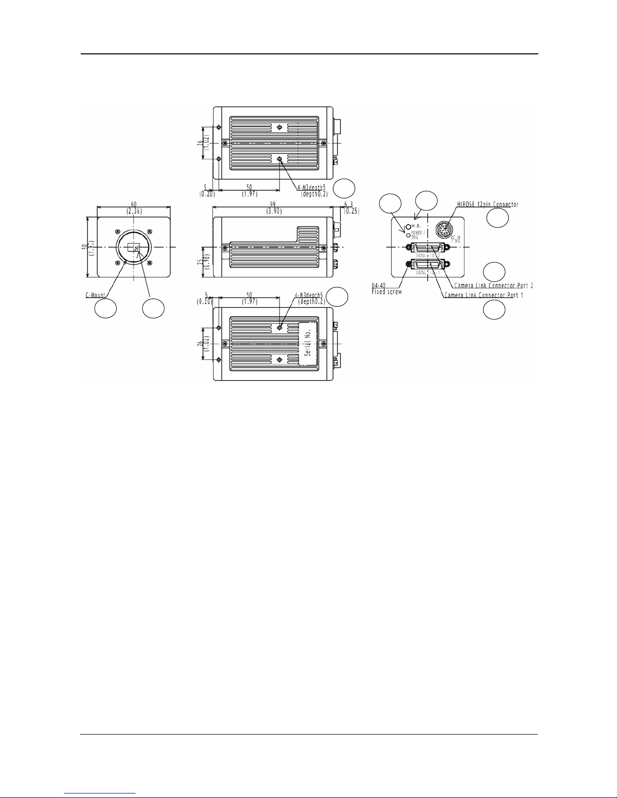
4. Locations and Functions
8
8
7
6
3
4
5
2
1
1 Lens mount of C-mount type. *1)
2 RGB Prism with 3 x 1/3” CCD sensors
3 Camera Link base connector 1
4 Camera Link medium connector 2
5 12 pin connector for DC +12V power external sync signals
6 LED for power and trigger indication
7 Switch for 1 push white balance
8 Mounting holes 8 x M3deept5.
*1) Note: Rear protrusion on C-mount lens must be less than 4.0mm
Fig. 1. Locations
- 3 -
Page 5
CV-M9 CL
5. Pin Assignment
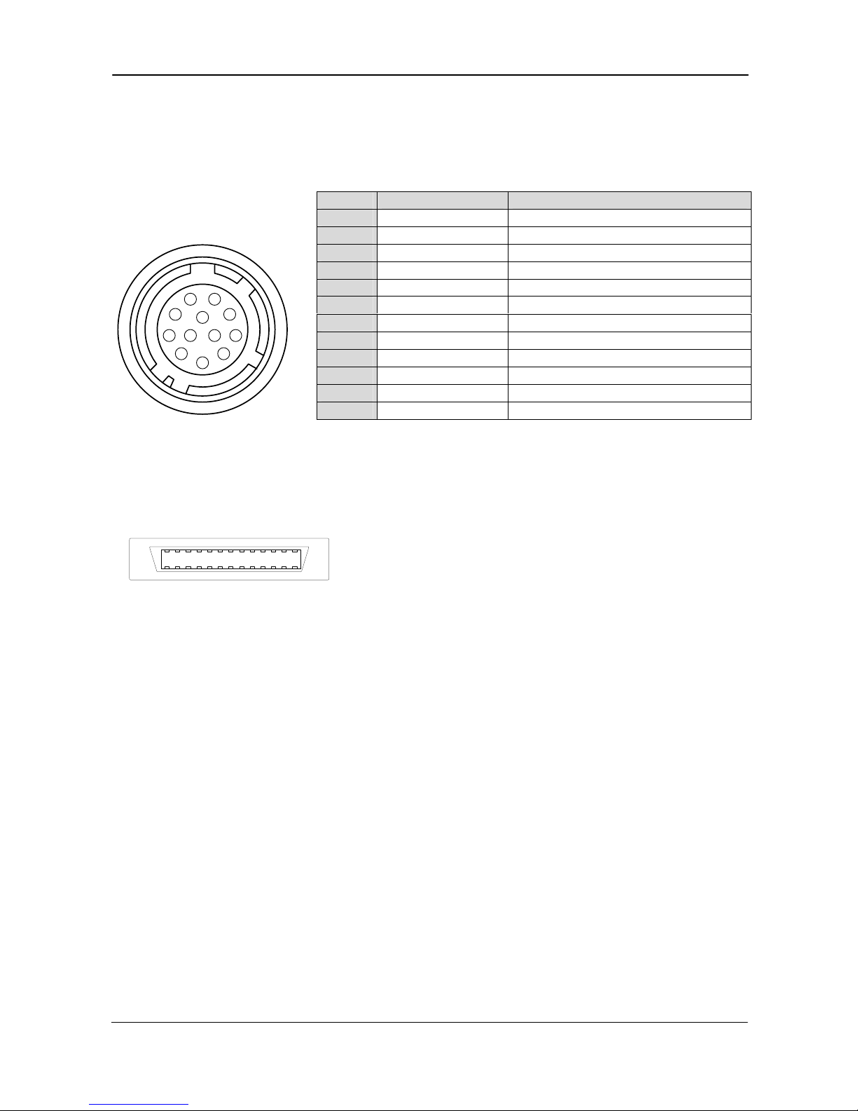
5.1. 12-pin Multi-connector (DC-IN/Trigger)
Type: HR10A-10R-12PB-01
(Hirose) male.
(Seen from rear of camera.)
Notes:
*1) See “7. Configuring the Camera” for more information.
Pin no. Signal Remarks
1 GND
2 +12 V DC input
3 GND
4 Iris video
Only Contin. and RCT mode. TR=0, TR=4
5 GND
6 RXD in
RXD in HR, or CL. SW301.1 off for CL *1)
7 TXD out
TXD in HR, or CL. SW301.1 off for CL *1)
8 GND
9 XEEN out
Low during exposure
10 Trigger in
TI=1 or in CL (TI=0). SW301.2 on for 75Ω
11 +12 V DC
12 GND
3
4
5
6
7
8
9
10
11
12
1
2
SW301.1 Off for CL. ON for 12 p HR. (SW301.2 is for trig 75Ω).
Fig. 2. 12-pin connector. Factory settings are shown in Bold Italic
5.2. Digital Output Connector for Camera Link
Type: 26 pin MRD connector
13
14
1
26
3M 10226-1A10JL
Fig. 3. Camera Link connector
The digital output signals follow the Camera Link standardized multiplexed signal output
interface. Camera Link base configuration is used for 3 x 8 bit RGB signal. The interface circuit is
build around the NS type DS90CR285MTD.
The following signals are found on the Digital Output Connector:
SerTC RXD serial data to camera
(SW301.1. Off for CL. On for HR)
SerTFG TXD serial data to frame grabber (SW301.1. Off for CL. On for HR)
CC1 Trigger input
(TI=0 for CL. TI=1 for 12 pin HR)
CC2 Factory use
X0 to X3 Camera Link multiplexed data out
Xclk Camera Link clock. Used as pixel clock.
In the Channel Link X0 to X3 multiplexed signals the following signals are encoded.
D0 – D9 3 x 8 bit RGB video data out.
LVAL Line VALid. Video line data is valid. High for valid line.
FVAL Frame VALid. Video frame data is valid. High for valid frame.
DVAL Data VALid. Effective video pixel data is valid. High for valid data.
EEN Exposure ENable. High during exposure.
The polarity is positive and TRIG in negative as factory setting.
For Camera Link interface principle diagram please check Fig. 7.
- 4 -
Page 6
CV-M9 CL
5.3. Input and output circuits
In the following schematic diagrams the input and output circuits for video and timing signals
are shown.
GND
75
Video
Output
800 mV
GND
75
Video
Output
GND
75
Video
Output
800 mV
800 mV
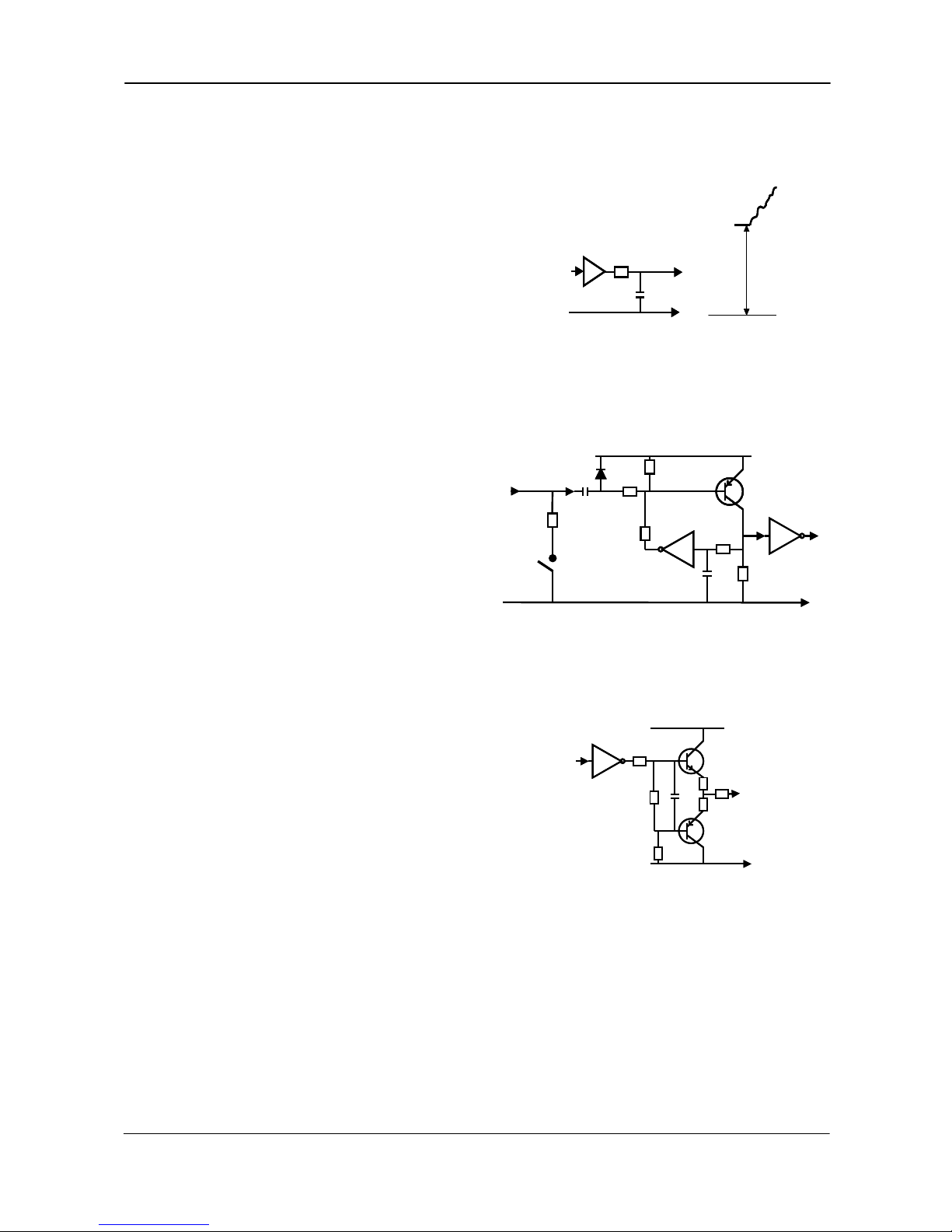
5.3.1. Iris video output
This signal can be used for lens iris control
In Continuous and Reset Continuous Trigger
Mode. The signal is taken from the CCD sensor output
before the gain circuit.
The iris video output is 0.7 Vpp from 75 Ω.
The signal is without sync.
Fig. 4. Iris video output.
5.3.2. Trigger input
With TI=1, the trigger input is on pin #10 on 12
pin connector. The input is AC coupled. To allow
a long pulse width, the input circuit is a flip flop,
which is toggled by the negative or positive
differentiated spikes caused by the falling or
rising trigger edges.
GND
+5V
15k
TTL
1k
GND
100n
1k
68k
100k
1n
75Ω
Trig input
pin #10
SW301.2
GND
+5V
15k
TTL
1k
GND
100n
1k
68k
100k
1n
75Ω
Trig input
pin #10
SW301.2
The trigger polarity can be changed by TP=1.
Trigger input level 4 V ±2 V. It can be
terminated by SW301.2: ON for 75Ω. OFF for TTL.
The trigger inputs can be changed to
Camera Link. (TI=0 for CL)
Fig. 5. Trigger input.
5.3.3. EEN output
GND
+5V
2
2
10k
2k2
75
TTL
100
Pin #9
XEEN
output
GND
+5V
2
2
10k
2k2
75
TTL
100
Pin #9
XEEN
output
XEEN is found on pin #9 on 12 pin HR connector.
The output circuit is 75 Ω complementary emitter
followers. It will deliver a full 5 volt signal.
Output level ≥4 V from 75Ω. (No termination).
XEEN is low during exposure.
EEN is found in Camera Link. It is high during
exposure.
Fig. 6. EEN output
- 5 -
Page 7
CV-M9 CL
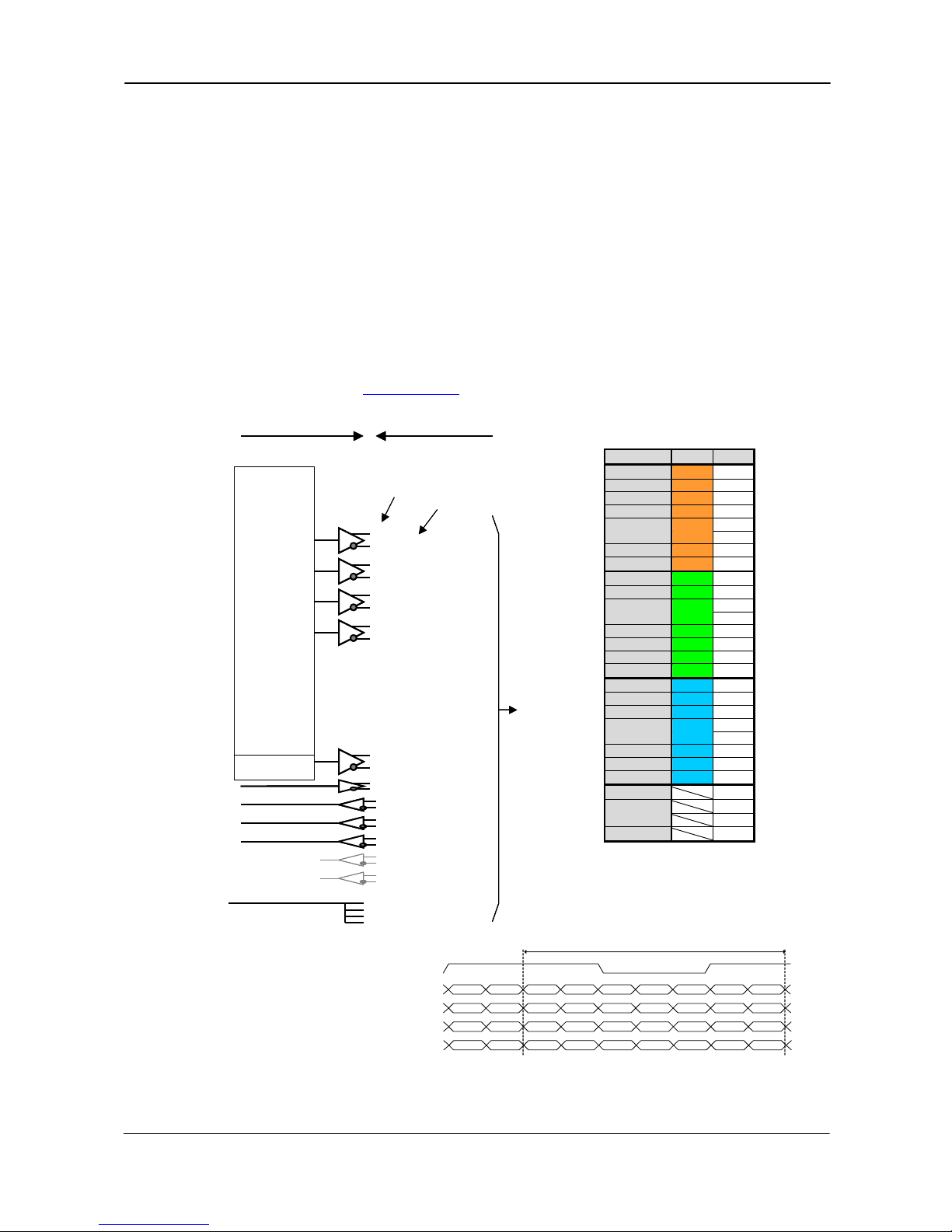
5.3.3. Camera Link interface
The video output is Camera Link with either 3 x 8 bit RGB video placed in a base configuration,
or 3 x 10 bit RGB placed in a Camera Link medium configuration. The digital output signals
follow the Camera Link standardized multiplexed signal output interface. The Camera Link
output driver is NS type DS90CR285MTD.
The data bits from the digital video, FVAL, LVAL, DVAL and EEN are multiplexed into the twisted
pairs, which are a part of the Camera Link. Trigger signals and the serial camera control are
feed directly through its own pairs. The trigger input can also be TTL on the 12 pin connector.
(TI=0 for CL. TI=1 for 12 pin HR). Factory setting is CL.
The serial camera control can be switches between the 12 pin connector or CL by the internal
switch SW301.1. Factory setting is CL.
The 26 pin MDR connector pin assignment follows the Camera Link base configuration.
For a detailed description of Camera Link specifications, please refer to the Camera Link
standard specifications found on www.jai.com
1
14
13
26
X0
X1
X2
X3
Xclk
SerTFG
SerTC
CC1
CC2
CC3
CC4
Sheilds
4 x
7-1
MUX
8bit 10bit
D2 D0
D3 D1
D4 D2
D5 D3
D6 D4
D7 D5
D8 D6
D9 D7
NC D8
NC D9
NC NC
NC NC
NC NC
NC NC
NC NC
NC NC
NC NC
NC NC
NC NC
NC NC
NC NC
NC NC
NC NC
NC NC
LVAL
FVAL
DVAL
EEN
Pclk
A 0 Tx0
A1 Tx1
A2 Tx2
A3 Tx3
A4 Tx4
A 5 Tx6
A 6 Tx27
A 7 Tx5
B 0 Tx7
B 1 Tx8
B 2 Tx9
B 3 Tx12
B 4 Tx13
B 5 Tx14
B 6 Tx10
B 7 Tx11
C 0 Tx15
C 1 Tx18
C 2 Tx19
C 3 Tx20
C 4 Tx21
C 5 Tx22
C 6 TX16
C 7 Tx17
Tx24
Tx25
Tx26
Tx23
Txclk
15
2
16
3
17
4
19
6
18
5
21
8
7
20
22
9
10
23
24
11
12
25
Pair 1
Pair 2
Pair 3
Pair 5
Pair 4
Pair 7
Pair 6
Pair 8
Pair 9
Pair 10
Pair 11
Sheilds
TXD out
RXD in
Ext. trig 1 in
Ground
Signal
Connector pin
CV-A33 Camera Camera Link Cable
Camera Signals
To
Frame
Grabber
Ext. Trig 2 in
Camera Link
Pin
Port/Signal 8bit Pin No.
Port A0 R D0 Tx0
Port A1 R D1 Tx1
Port A2 R D2 Tx2
Port A3 R D3 Tx3
Port A4 R D4 Tx4
Port A5 R D5 Tx6
Port A6 R D6 Tx27
Port A7 R D7 Tx5
Port B0 G D0 Tx7
Port B1 G D1 Tx8
Port B2 G D2 Tx9
Port B3 G D3 Tx12
Port B4 G D4 Tx13
Port B5 G D5 Tx14
Port B6 G D6 Tx10
Port B7 G D7 Tx11
Port C0 B D0 Tx15
Port C1 B D1 Tx18
Port C2 B D2 Tx19
Port C3 B D3 Tx20
Port C4 B D4 Tx21
Port C5 B D5 Tx22
Port C6 B D6 Tx16
Port C7 B D7 Tx17
LVAL Tx24
FVAL Tx25
DVAL Tx26
EEN Tx23
Camera Link bit allocation
D0 = LSB. D7 = MSB
Base configuration
TxCLK
A7
A6
EEN
C7
B7
B6
A7
A6
C6
C3
C2
DVAL
FVAL
C5
C4
C3
C2
LVAL
B2
B1
C1
C0
B4
B3
B2
B1
B5
A1
A0
B0
A5
A3
A2
A1
A0
A4
TxOUT3
TxOUT2
TxOUT1
TxOUT0
1 pi xel cycl e
Timing
Fig. 7. Principle diagram for 3 x 8 bit RGB in Camera Link base configuration
- 6 -
Page 8
CV-M9 CL
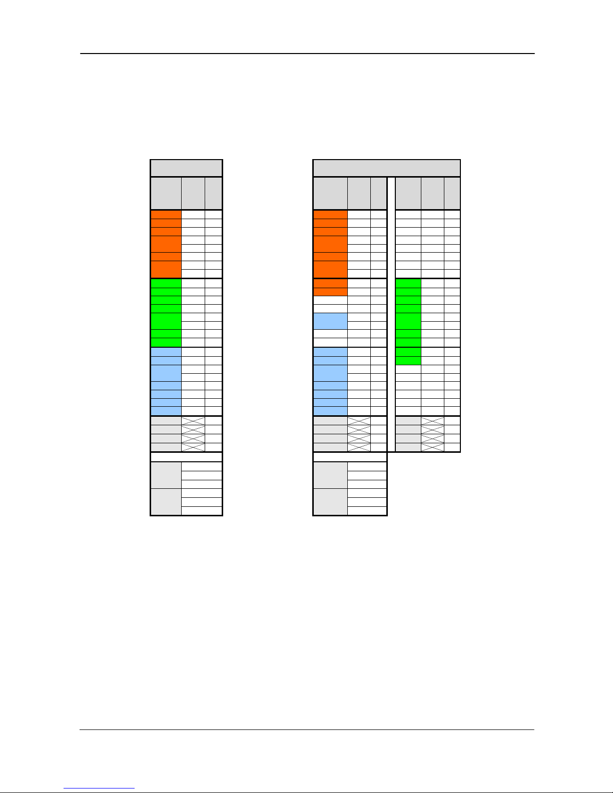
5.3.5. Bit allocation in Camera Link connectors
The CV-M9CL camera has outputs for the RGB signals in Camera Link. The RBG output can be
allocated as 3 x 8 bit in Camera Link base configuration. Connector 1 is then used.
For 3 x 10 bit RGB output in Camera Link, 2 connectors are used in medium configuration.
The below 2 tables shows the bit allocations in the Camera Link connectors.
CL base configuration
Connector 1
CL medium configuration
Connector 1 Connector 2
Camera
signals
8 bit
Camer
a
Link
Port
CL
Pin
No.
Camera
signals
10 bit
Camer
a
Link
Port
CL
Pin
No.
Camera
signals
10 bit
Camer
a
Link
Port
CL
Pin
No.
R D0 Port A0 Tx0 R D0 Port A0 Tx0 NC Port D0 Tx0
R D1 Port A1 Tx1 R D1 Port A1 Tx1 NC Port D1 Tx1
R D2 Port A2 Tx2 R D2 Port A2 Tx2 NC Port D2 Tx2
R D3 Port A3 Tx3 R D3 Port A3 Tx3 NC Port D3 Tx3
R D4 Port A4 Tx4 R D4 Port A4 Tx4 NC Port D4 Tx4
R D5 Port A5 Tx6 R D5 Port A5 Tx6 NC Port D5 Tx6
R D6 Port A6 Tx27
R D6 Port A6 Tx27 NC Port D6 Tx27
R D7 Port A7 Tx5 R D7 Port A7 Tx5 NC Port D7 Tx5
G D0 Port B0 Tx7 R D8 Port B0 Tx7 G D0 Port E0 Tx7
G D1 Port B1 Tx8 R D9 Port B1 Tx8 G D1 Port E1 Tx8
G D2 Port B2 Tx9 NC Port B2 Tx9 G D2 Port E2 Tx9
G D3 Port B3 Tx12
NC Port B3 Tx12 G D3 Port E3 Tx12
G D4 Port B4 Tx13
B D8 Port B4 Tx13 G D4 Port E4 Tx13
G D5 Port B5 Tx14
B D9 Port B5 Tx14 G D5 Port E5 Tx14
G D6 Port B6 Tx10
NC Port B6 Tx10 G D6 Port E6 Tx10
G D7 Port B7 Tx11
NC Port B7 Tx11 G D7 Port E7 Tx11
B D0 Port C0 Tx15
B D0 Port C0 Tx15 G D8 Port F0 Tx15
B D1 Port C1 Tx18
B D1 Port C1 Tx18 G D9 Port F1 Tx18
B D2 Port C2 Tx19
B D2 Port C2 Tx19 NC Port F2 Tx19
B D3 Port C3 Tx20
B D3 Port C3 Tx20 NC Port F3 Tx20
B D4 Port C4 Tx21
B D4 Port C4 Tx21 NC Port F4 Tx21
B D5 Port C5 Tx22
B D5 Port C5 Tx22 NC Port F5 Tx22
B D6 Port C6 Tx16
B D6 Port C6 Tx16 NC Port F6 Tx16
B D7 Port C7 Tx17
B D7 Port C7 Tx17 NC Port F7 Tx17
LVAL Tx24
LVAL Tx24 LVAL Tx24
FVAL Tx25
FVAL Tx25 FVAL Tx25
DVAL Tx26
DVAL Tx26 DVAL Tx26
EEN Tx23
EEN Tx23 NC Tx23
TXD out Ser TFG TXD out Ser TFG
RXD in Ser TC RXD in Ser TC
Trig in CC1 Trig in CC1
NC CC2 NC CC2
NC CC3 NC CC3
NC CC4 NC CC4
Fig. 8. Connector 1 base configuration and connector 1 and 2 medium configuration
- 7 -
Page 9
CV-M9 CL
6. Functions and Operations
6.1. Basic functions
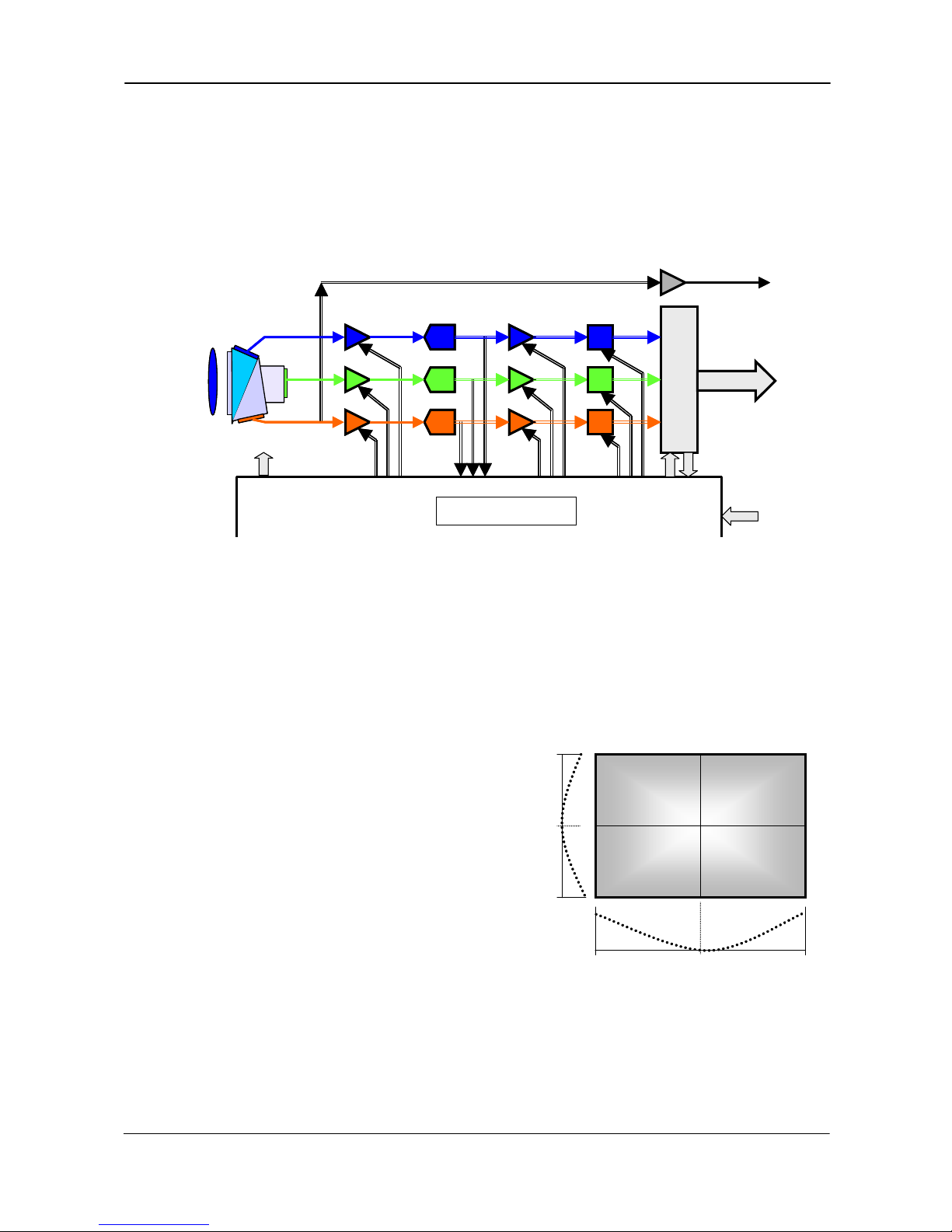
A 16-bit processor controls all functions in the CV-M9CL camera. The CCD sensor output is
normalized in preamplifiers. The signals are then digitized to 12 bits. Digital gain control and
look-up tables can do signal processing in 12 bits before it is truncated to a 10 or 8 bit camera
link signal.
A/D
A/D
A/D
16 bit digital processing
12 bit 8/10 bit
Camera Link
CL
Inter
face
B
R
G
Prism
Timing
CL
A. gain D. Gain
Shading
map
Knee
Point
slope
12 bit 10 bit
Iris video
RGB signal
RGB input
Shading
data
A/D
A/D
A/D
16 bit digital processing
12 bit 8/10 bit
Camera Link
CL
Inter
face
B
R
G
Prism
Timing
CL
A. gain D. Gain
Shading
map
Knee
Point
slope
12 bit 10 bit
Iris video
RGB signal
RGB input
Shading
data
Fig. 9. Principle diagram for signal processing
6.1.1. Dynamic shading correction
The CV-M9CL camera has a digital shading correction circuit, which can compensate for prism
chromatic shading, for lens vignetting and for CCD shading. It makes the choice of lenses wider.
The camera with a given lens and a given f-number is looking on a homogeneous white scene.
A horizontal profile of the shading in 128 points is made for the 3 colors.
A vertical profile of the shading in 96 points is
made for the 3 colors.
The result is stored as gain difference from the
image centre.
Data from this h and v profile is used to adjust
the R, B and G gain depending of the H and V
position. The resulting image is then
compensated for shading caused by the lens,
prism and CCD.
The lens used is a Fujinon 15mm F2.2.
The iris is set to F5.6.
With the camera control tool it is possible to
customize the correction for a given set-up, and
store the corrections in a file. Refer to chapter 6.5.1.
0 127
0
95
H shading data
V
shading
data
0 127
0
95
H shading data
V
shading
data
Fig. 10. Shading correction.
Note: Lens requirements.
To obtain the best possible image, it is recommended to use lenses designed for 1/3” 3 CCD
cameras. The shading depends of the focal length and the iris setting. Avoid wide-angle lenses,
and do not use an iris setting fully open.
- 8 -
Page 10
CV-M9 CL
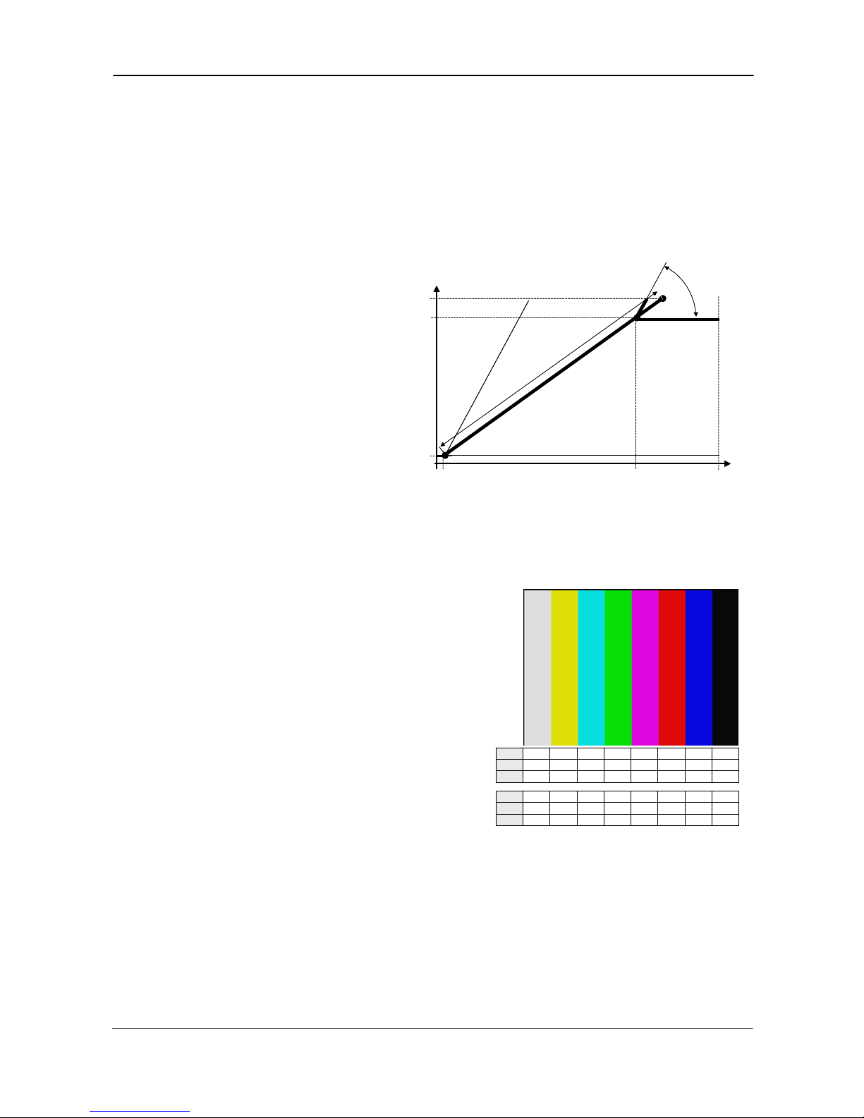
6.1.2. Knee function
The internal video signal is 12 bit, and only 8 or 10 bit is output. By help of the look-up table
function it is possible to compress or expand the video signal to change the dynamic range. It
can be done individually for R, G and B with the knee function.
The Knee function is given by 2 sets of parameters. Knee point and slope. These 2 sets of data
determine how the output would be with reference to the input data. This conversion is done by
the hardware (FPGA) doing calculations using the knee data.
The normal transfer function is with a slope 1:1. From a given point and up, the slope can be
changed. This point is the knee point parameter, and its range is from 0 to 1023 referring to the
video output. Factory setting is 890.
10 bit Digital
video output
S
l
o
p
e
2
0
0
32
890
1023
2848
[LSB]
S
l
o
p
e
1
4095
100%
K
n
e
e
a
d
j
u
s
t
r
a
n
g
e
102
Slope 0
Slope
adust range
12 bit CCD signal
The knee function
is individual RGB
Slope 0
S
l
o
p
e
2
10 bit Digital
video output
S
l
o
p
e
2
0
0
32
890
1023
2848
[LSB]
S
l
o
p
e
1
4095
100%
K
n
e
e
a
d
j
u
s
t
r
a
n
g
e
102
Slope 0
Slope
adust range
12 bit CCD signal
The knee function
is individual RGB
Slope 0
S
l
o
p
e
2
The new slope can be set from 1:0 to 1:2.
A slope 1:0 is a clipper function, which
will limit the output signal. A slope 1:2
will function as a 2 times contrast
expanding function.
The slope parameter range is from 0 to
4095.
0 is slope 1:0.
2048 is slope 1:1.
4095 is slope 1:2.
Factory setting is 800. The slope is then
800/2048 =1: 0.39.
Fig. 11. Knee function.
6.1.3. Color bar for test
8222822282228222
Blue
8888222222222222
Green
8822222288222222
Red
8222822282228222
Blue
8888222222222222
Green
8822222288222222
Red
Values
in 8 bit
32890328903289032890
Blue
32323232888890890890
Green
32328908903232890890
Red
32890328903289032890
Blue
32323232888890890890
Green
32328908903232890890
Red
Values
in 10 bit
The CV-M9CL camera has a build in color bar
generator. When it is activated, the output image
will be as shown below. The RGB values are shown
for both 8 and 10 bit output.
Fig. 12. Color bar RGB values
- 9 -
Page 11
CV-M9 CL
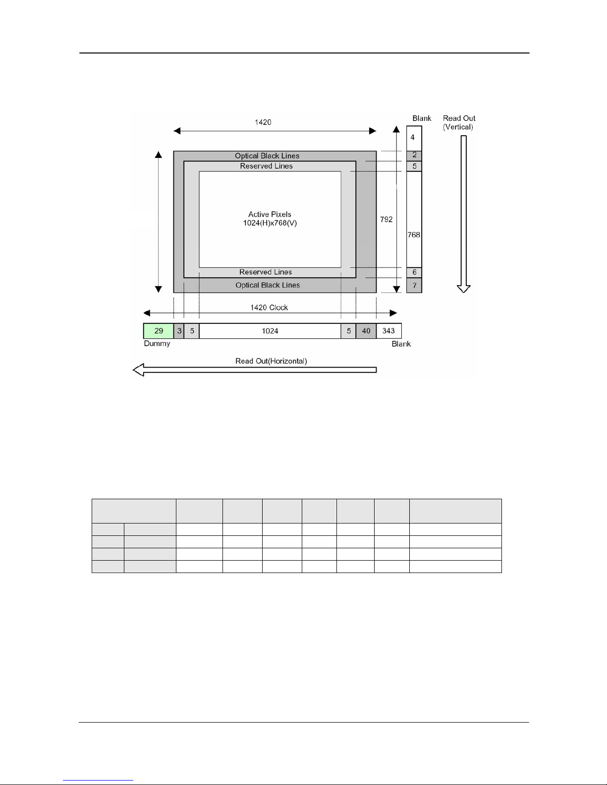
6.2. Sensor Layout and timing
6.2.1. CCD Sensor Layout
788
Fig. 13. CCD sensor layout
Table for scanning.
The below table shows the start line, the stop line and the number of active lines in the vertical
centred scanned area on the CCD sensor. The front and back lines are the lines used for the fast
dump readout used in partial scanning.
Scanning
Start
line #
End
line #
Active
lines
Front
lines
Back
lines
Blank
lines Remarks
SC=0 Full 1 768 768 12 8 4 Refer to fig. 15.
SC=1 1/2 192 576 384 54 50 4 Refer to fig. 16.
SC=2 1/4 288 480 192 78 74 4 Refer to fig. 17.
SC=3 1/8 336 432 96 90 86 4 Refer to fig. 18.
- 10 -
Page 12
CV-M9 CL
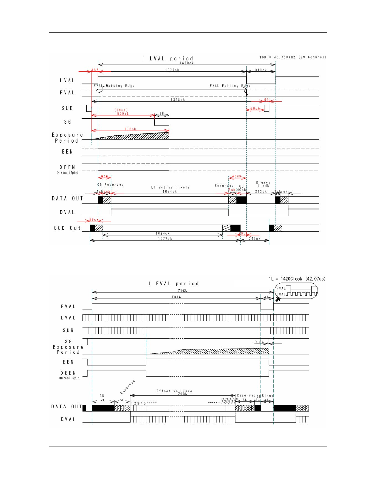
6.2.2. Horizontal timing
Fig. 14. Horizontal timing
6.2.3. Vertical timing
1L = 42.07 µs
Fig. 15. Vertical timing for full scan
- 11 -
Page 13

CV-M9 CL
6.2.4. Partial Scanning
1L = 42.07 µs
Fig. 16 Vertical timing for 1/2 partial scan
1L = 42.07 µs
Fig. 17 Vertical timing for 1/4 partial scan
- 12 -
Page 14

CV-M9 CL
Fig. 18 Vertical timing for 1/8 partial scan
6.2.5. Vertical binning
Fig. 19. Horizontal timing for V binning.
- 13 -
Page 15

CV-M9 CL
1L = 50.96 µs
Fig. 20. Vertical timing for V binning.
6.3. Input/Output of Timing Signals
For settings, please refer to chapter “7. Configuring the Camera”
6.3.1. Input of external trigger
Input of external trigger signal can be via Camera Link (TI=0). Factory setting. Or as TTL on the
12 pin connector pin 10. (TI=1). Here it should be 4.0 Vp-p ±2.0 V from a 75 Ω source. The
trigger input signal can be 75 Ω terminated. Factory setting is TTL. For 75 Ω termination
SW301.2 should be ON.
6.3.2. Output of EEN (XEEN)
The Exposure Enable signal EEN indicate that the accumulation is ongoing. It can be used for
controlling a strobe flash. The XEEN signal is found on the 12 pin connector pin 9. It is 4.0 Vp-p
from a 75 Ω source. The EEN signal is also found in Camera Link.
- 14 -
Page 16

CV-M9 CL
6.4. Operation Modes
This camera can operate in 5 primary modes.
1. TR=0 Con Normal continuous Mode Pre-selected exposure.
2. TR=1 EPS Edge Pre-select Mode Pre-selected exposure.
3. TR=2 PWC Pulse Width Control Mode Pulse width controlled exposure.
4. TR=3 SG Sensor Gate Control Strobe illum. exp. with delayed read out
5. TR=4 RCT Reset Continuous Trigger Pre-selected exposure.
The triggered accumulation in EPS, PWC and RTC mode can be LVAL synchronous or LVAL asynchronous.
In LVAL synchronous accumulation, a new exposure can be started while the previous frame is
read out. The new exposure should not be finished before the frame is read out. FVAL shall be
low for >2 LVAL. The maximum frame rate in trigger modes can then be close to the frame rate
in continuous mode.
The minimum trigger interval should be longer than (1 FVAL+2 LVAL).
To avoid <1L time jitter in LVAL synchronous mode, it is recommended to synchronize the trigger
to LVAL.
In LVAL a-synchronous accumulation, a new trigger must not be applied before the previous
frame is read out. (FVAL is low).
The minimum trigger interval should be longer than (exposure time + 1 FVAL+3 LVAL).
Refer to chapter 6.4.1. and 6.4.2. for accumulation details.
Refer to chapter “7. Configuring the Camera” for details in mode settings.
Mode and function matrix.
The following table shows which functions will work in the different modes.
Func. Shutter
SM=
Part. sc
SC=
Binning
BI=1
Smearl
SL=1
Accum
LS=
Iris
video
Mode TR= 0 1 0 to 3 0 1 out Remarks
Cont. 0
√ √ √ √
- - -
√
EPS 1
√ √ √ √ √ √ √
-
PWC 2 - -
√ √ √ √ √
-
SG 3 - - - - - - - -
RCT 4
√ √ √ √ √ √ √ √
√ = ok, - = no function
Partial scanning has priority over Binning.
- 15 -
Page 17

CV-M9 CL
6.4.1. LVAL synchronous accumulation
With LS=0, the accumulation will start synchronously with LVAL. The trigger pulse should be
longer than 2 LVAL intervals, and the accumulation will then start at the first LVAL after the
trigger leading edge. The exposure start delay will be up to 1 line. (42.07 µsec.).
In EPS mode the exposure stops 0.5 L after the selected shutter time, (in number of LVAL).
In PWC mode the exposure stops 0.5 L after the first LVAL after the trigger trailing edge. It
results in up to 1 LVAL jitter.
In trigger modes with LVAL synchronous accumulation, a new exposure can be started while the
previous frame is read out. The new exposure should not finish before the frame is read out.
FVAL shall be low for >2 LVAL. The maximum frame rate in trigger modes can then be close to
the frame rate in continuous mode.
Minimum trigger interval
≥
(1 FVAL + 2 LVAL).
Important notes on using this mode.
In LVAL synchronous PWC mode exposure jitter up to 1 LVAL can be the result, if the trigger
trailing edge is not synchronized to LVAL.
Fig. 21. LVAL synchronous accumulation in EPS mode
Fig. 22. LVAL synchronous accumulation in PWC mode
- 16 -
Page 18

CV-M9 CL
6.4.2. LVAL a-synchronous accumulation
With LS=1, the accumulation will start immediately after the trigger leading edge.
The exposure start delay is 9.7 µsec.
In EPS mode the exposure stops 0.5 L after the selected shutter time, (in number of LVAL).
In PWC mode the exposure stops 0.5 L after the trigger trailing edge.
A new trigger must not be applied before the previous frame is read out. (FVAL is low).
Minimum trigger interval
≥
( exposure time + 1 FVAL + 3 LVAL).
Important notes on using this mode.
In LVAL a-synchronous PWC mode there is no exposure jitter.
Fig. 23. LVAL a-synchronous accumulation in EPS mode
Fig. 24. LVAL a-synchronous accumulation in PWC mode
- 17 -
Page 19

CV-M9 CL
6.4.3. Continuous operation
For applications not requiring asynchronous external trigger, but should run in continuous
operation, this mode is used.
In this mode it possible to use a lens with video controlled iris.
For timing details, refer to fig. 13. through fig. 20.
To use this mode:
Set function: Trigger mode to “Continuous” TR=0
Scanning SC=0 through 3
Vertical binning BI=0, BI=1
Shutter mode normal, programmable SM=0 through 2
Shutter speed SH=0 through 11
Programmable exp. PE=0 through 791
Other functions and settings
Input:
Important notes on using this mode
For timing details, refer to fig. 13. through fig. 20.
- 18 -
Page 20

CV-M9 CL
6.4.4. Edge Pre-select Trigger Mode
An external trigger pulse initiates the capture, and the exposure time (accumulation time) is the
fixed shutter speed set by SH or PE. The accumulation can be LVAL synchronous or LVAL asynchronous.
The resulting video signal will start to be read out after the selected shutter time.
For timing details, refer to fig. 13. through fig. 20. and fig. 25.
To use this mode:
Set function: Trigger mode to “Edge pre-select” TR=1
Scanning SC=0 through 3
Vertical binning BI=0, BI=1
Shutter mode to normal or programmable SM=0 through 2
Shutter speed SH=0 through 11
Programmable exp. PE=0 through 791
Accumulation LVAL synch. or a-synch. LS=0, LS=1
Other functions and settings
Input: Ext. trigger. Camera Link or 12 HiRose TI=0, TI=1
Important notes on using this mode
Trigger pulse >2 LVAL to <1 FVAL
To avoid ≤ 1 LVAL jitter in synch. accum, synchronize the trigger to LVAL.
Minimum trigger interval in synch. accum. ≥ (1 FVAL + 2 LVAL).
Minimum trigger interval in a-synch. accum. ≥ ( exposure time + 1 FVAL + 3 LVAL).
Fig. 25. Edge pre-select. LVAL synchronized.
- 19 -
Page 21

CV-M9 CL
6.4.5. Pulse Width Control Trigger Mode
In this mode the accumulation time is equal the trigger pulse width. Here it is possible to have
long time exposure. The maximum recommended time is <2 seconds.
The accumulation can be LVAL synchronous or LVAL a-synchronous.
The resulting video signal will start to be read out after the trigger rising edge.
For timing details, refer to fig. 13. through fig. 20. and fig. 26.
To use this mode:
Set function: Trigger mode to “Pulse width control”. TR=2
Scanning SC=0 through 3
Vertical binning BI=0, BI=1
Accumulation LVAL synch. or a-synch. LS=0, LS=1
Other functions and settings
Input: Ext. trigger. Camera Link or 12 HiRose TI=0, TI=1
Important notes on using this mode
Trigger pulse width >2 LVAL to <1 seconds.
To avoid ≤ 1 LVAL jitter in synch. accum, synchronize the trigger to LVAL.
Minimum trigger interval in synch. accum. ≥ (1 FVAL + 2 LVAL).
Minimum trigger interval in a-synch. accum. ≥ ( exposure time + 1 FVAL + 3 LVAL).
Fig. 26. Pulse width control. LVAL synchronized.
- 20 -
Page 22

CV-M9 CL
6.4.6. Reset Continuous Trigger mode
The RCT mode is in principle the same as normal continuous mode. The difference is that an
external trigger pulse will immediately stop the video read out and reset and restart the vertical
timing. After a fast dump read out (198 L = 8.33ms), a new triggered exposure is started and
read out as normal. The fast dump read out is performed with a speed 4 times faster as normal.
If no further trigger pulses are applied, the camera will continue in normal mode. This fast dump
read out has the same effect as “smearless read out”. Smear over highlighted areas are reduced
for the triggered frame.
The reset continuous trigger mode makes it possible to use a lens with video controlled iris
together with a triggered exposure.
For timing details, refer to fig. 13. through fig. 20. and fig. 27.
To use this mode:
Set function: Trigger mode to “Reset continuous trigger”. TR=4
Scanning SC=0 through 3
Vertical binning BI=0, BI=1
Shutter mode normal, programmable or auto SM=0 through 2
Shutter speed SH=0 through 11
Programmable exp. PE=0 through 791
Accumulation LVAL synch. or a-synch. LS=0, LS=1
Other functions and settings
Input: Ext. trigger. Camera Link or 12 HiRose TI=0, TI=1
Important notes on using this mode
Trigger pulse >2 LVAL to <1 FVAL
To avoid ≤ 1 LVAL jitter in synch. accum, synchronize the trigger to LVAL.
Minimum trigger interval ≥ (exposure time + 1 FVAL + 2 LVAL + 198 LVAL).
A new trigger must not be applied before the previous triggered frame is read out.
LVAL
DVAL
DATA OUT
SUB
SG
FVAL 1
EEN
Ex t .T r ig1
Exposu re
Pe r iod
FVAL 2
JA I S tanda rd
Came ra L ink
High Speed
Transfer
Con t inuous Da ta
Smea r less (198L )
Min.:2L
T r igge red Da ta
Con t inuous Da ta
Fig. 27. Reset Continuous Trigger
- 21 -
Page 23

CV-M9 CL
6.4.7. Sensor Gate Control
This function is for applications with strobe flash illuminations or long time accumulations up to
several frames. The external Sensor Gate control signal will disable the internal SG pulse so the
accumulation will continue during the next frame. As long as the sensor gate control signal is
low, the accumulation will continue. The resulting video is read out after the first FVAL (or SG),
following the trailing edge of the Sensor Gate Control signal. Fig. 28.
To disable the internal SG pulse, the sensor gate control signal should be low 2 µs before.
Fig. 29. shows the sensor gate signal setup time and hold time. It is inside the first line after
FVAL goes low.
For timing details, refer to fig. 13. through fig. 20. and fig. 28. - 29.
To use this mode:
Set function: Trigger mode to “Sensor gate control”. TR=3
Scanning SC=0
Vertical binning BI=0
Other functions and settings
Input: Ext. SG control to trigger input, CL or 12 pin HR
Important notes on using this mode
1L = 42.07 µs
Fig. 28. Sensor Gate Control
Minimum setup and hold time for external sensor gate control signal is shown in relation to the first LVAL after FVAL
falling edge.
Fig. 29. Sensor Gate control signal minimum specifications
- 22 -
Page 24

CV-M9 CL
6.5. Other Functions.
Scanning. SC=0 through 3.
The CCD scanning format can be selected between full or partial scanning. With partial scanning
only the vertical central part of the CCD sensor is read out with a higher frame rate. The partial
scan is done by a fast dump read out of the lines in the vertical ccd register down to the top of
the partial image. The partial part of the image is read out with normal speed. The lines below
the partial image is read out and dumped with a high speed. With partial scan the shutter speed
is limited to be shorter than the frame read out time. There is no limitation in PWC mode.
Bit allocation. BA=0, BA=1.
The video output in Camera Link can be
selected to be 10 or 8 bits (BA=0, BA=1). For
8 bits only the 8 most significant bits are
output.
The relations between CCD signal output,
normal analog video signal and the digital
video signal are shown.
CCD out Analog Signal
Digital
Out(10bit)
Digital
Out(8bit)
Black
Setup 3.6%
25mV
32LSB 8LSB
200mV 700mV 890LSB 222LSB
>230mV 800mV 1023LSB 255LSB
Digital video out
0 25 700 800
[mV]
Analogue
0
32
890
1023
100%
level
White
clip level
Black level
[LSB]
Video out
0 200
>230
[mV]
CCD out
[LSB]
0
8
222
255
10 bit
8 bit
Digital video out
0 25 700 800
[mV]
Analogue
0
32
890
1023
100%
level
White
clip level
Black level
[LSB]
Video out
0 200
>230
[mV]
CCD out
0 25 700 800
[mV]
Analogue
0
32
890
1023
100%
level
White
clip level
Black level
[LSB]
Video out
0 200
>230
[mV]
CCD out
[LSB]
0
8
222
255
10 bit
8 bit
Fig. 30. Bit allocation.
Binning. BI=0 through BI=1.
Binning mode is a function where the signal charge from 2 or more adjacent pixels are added
together and read out as one pixel. A resulting full frame with lower spatial resolution can be
read out with a higher rate, and higher sensitivity. The CV-M9CL has vertical binning 2:1.
Vertical binning is done by adding the pixel charge from adjacent lines together in the horizontal
ccd register. It is done by multiple shift pulses to the vertical ccd register.
Lowest shutter speed is reduced to be shorter than the frame read out time. There are no
limitations in PWC mode.
Smearless readout. SL=1.
This function will reduce the unwanted smear signal from a highlighted scene when a short
exposure time is used. It works in all trigger modes, but a dummy readout is performed before
the active accumulation is started. It will remove the smear above the highlighted parts in the
image, but there is still smear left below highlighted areas.
The trigger leading edge will start the dummy readout. It takes 198 LVAL (8.33ms) before the
exposure starts. The exposure stops and the resulting video signal is read out. This mode will
operate with full and partial scanning and with all binning modes.
Color bar. CBAR=0, CBAR=1.
The command CBAR=1 insert a standard color test bar on the output image, so it can be used for
calibration. For color bar specifications refer to chapter 6.1.3.
Shutter mode. SM=0, SM=1 and SM=2. SH=0 through SH=11 and PE=2 through PE=791.
With SM=0 this function selects the shutter from the 12 fixed steps (SH). With SM=1 from
programmable in 789 steps (PE). SM=2 is for individual programmable exposure of red, green and
blue. PER, PEG and PEB =2 through =791. It allows a wide range of manual color balance
adjusting.
- 23 -
Page 25

CV-M9 CL
RCT FVAL type. RF=0, RF=1.
This command selects the FVAL type in RCT mode. Refer to chapter 6.4.6. Reset Continuous
Trigger mode.
Trigger input select. TI=0, TI=1.
This function selects the trigger input to be through Camera Link (TI=0), or as TTL through the
12 pin Hirose connector (TI=1).
Trigger polarity. TP=0, TP=1.
The active trigger polarity is normal low (TP=0). It can be invert it to active high (TP=1).
Note: With TP=1 and TI=1, the first trigger pulse after power up will be ignored.
White balance. WB=0 through, WB=4.
By adjusting the R, G and B gain depending of the scene illumination color temperature it is
possible to have correct color balance in the video output. A white scene will be shown as a
white image. This white balance can be done in different ways.
WB=0 is for manual/one push white balance. In manual, the white balance can be changed by
the gain settings. The one push white balance function is also active here. WB=1 is continuous
white balance. WB=2, WB=3 and WB=4 are fixed values 3200K, 4600K and 5600K. Factory
adjusted to 3200K.
One push white balance. AW=0
If the command WB=0 is received, an automatic white balance is performed once. The result of
this function can be requested by the command AWRS?
lower rightlower middlelower left
middle rightmiddlemiddle left
upper rightupper middleupper left
lower rightlower middlelower left
middle rightmiddlemiddle left
upper rightupper middleupper left
FullFull
0
12
3
45 6
789
Set Auto White Balance area. WA=
This function makes it possible to set the one push white
balance sensing area to the area of interest. WA=0 is the
whole image, WA=1 through 9 are one of the 9 areas
shown.
Fig. 31. Auto white balance areas.
Request result of one push white balance. AWRS?
If the request AWRS? is received, the camera will answer with the result of the one push white
balance operation. “0” = complete, “1” scene is too bright, “2” scene too dark, “3” is timeout
error, “4” is busy, “5” limit and “6” balance can’t be done because camera is in trigger mode.
Master gain level. GA=-132 through, GA=+429
Sets the gain level for RGB. The range is –4dB to +13dB. GA=0 is 0dB.
Gain level red. GAR=-231 through GAR=+231.
The gain range for red is –7dB to +7 dB. GAR=0 is 0dB.
Gain level blue. GAB=-231 through GAB=+231.
The gain range for blue is –7dB to +7 dB. GAB=0 is 0 dB.
Black level green. BLG=0 through BLG=1023.
Set up level for green. Factory setting is 460.
Black level red. BLR=0 through BLR=1023
Set up level for red. Factory setting is 460.
Black level blue. BLB=0 through BLB=1023.
Set up level for blue. Factory setting is 460.
- 24 -
Page 26

CV-M9 CL
Knee function. KN=0, KN=1.
If KN=1 is received the knee function is enabled.
With the knee functions is possible to change the relation between CCD signal and the resulting
output video signal. With the function disabled, the transfer slope is 1:1.
The level where the slope should be changed is set with the knee point settings. Its range is from
0 to 1023 related to the video output. Factory setting is 890. (100%).
From the knee point and up, the slope can be changed from the normal 1:1. The slope
parameter range is from 0 to 4095, where 0 is slope 1:0, 2048 is slope 1:1, and 4095 is slope 1:2.
The slope range is from 0 to 2, where 0 is completely limitation (or clipping) and 2 is contrast
expanding. Factory setting is 800. The slope is then 800/2048 or 0.39
For details refer to 6.1.2. Knee function.
Knee point red. KPR=0 through KPR=1023
Knee point green. KPG=0 through KPG=1023
Knee point blue. KPB=0 through KPB=1023
Knee slope red. KSR=0 through KSR=4095
Knee slope green. KSG=0 through KSG=4095
Knee slope blue. KSB=0 through KSB=4095
Shading Mode. SDM=0, SDM=1.
If the command SDM=1 is received, the shading corrector is enabled. This corrector will
compensate for the color shading caused by the prism, for the circular shading caused by the
lens vignetting and for CCD sensor shading.
The parameters for shading corrections are factory loaded with a given lens and f-number.
For details refer to 6.1.1. Dynamic shading correction.
For customoized shading correction, please refer to chapter 6.5.1. Customized shading
correction.
LED for power and trigger.
On the camera rear a Light Emitter Diode is found. The light will be green when power is
connected. For trigger pulse input an amber flash will be seen.
Iris video output.
Iris
video out
0
700
930
100%
level
White
clip level
02
>265
[mV]
CCD out
[mV]
Iris
video out
0
700
930
100%
level
White
clip level
02
>265
[mV]
CCD out
[mV]
0000
On pin 4 on the 12 pin Hirose connector an analog
video signal is found. It can be used for iris
regulation if the camera is in continuous or RCT
mode.
The curve shows the relation between the CCD
signal output and the iris video output.
100% video is 700 mV. The iris video output is
without sync.
Fig. 32. Iris video output.
- 25 -
Page 27

CV-M9 CL
6.5.1. Customized shading correction.
From factory, the CV-M9CL camera is delivered with a shading correction adjusted to work with
homogeny lightening coming from a DC regulated halogen lamp at 3200K and a certain Fujinon
lens. This shading data stored in the factory area is also used for the 3 user areas. For other
fixed illumination and for another fixed lens in a specific setup, it makes sense to make a
temporary customized shading calibration.
When such calibration is done, it will be used in the camera until next power up. Here the old
factory shading data will be called and used.
With the Camera Control Tool it is possible to store the customized shading corrections in a file.
This file can then be loaded into the camera after next power up.
To make a customized shading calibration it is most important to avoid flickering of the
lightening like AC powered light and also reflections should be avoided – such effects will
interfere with the calibration. Apart from that the light temperature and the light density over
the area of interest should be exactly as for the real setup.
The camera setting has to be as follows:
• Master gain 0dB
• Individual gain 0dB
• Shutter off
• Trigger modes off - use Normal mode
• Binning and Partial scan off
• Use 10 bit output mode
• Shading corrector off
Continue with the following:
• Set up the illumination, as it should be in the real application.
• Place a perfectly flat white object (piece of paper) at the actual scene. No reflections
must be visible.
• Adjust the lens iris and focus to the level, which should be used in the real application.
• Make sure that the signal level at scene centre equals around 800LSB.
• When the above is okay then perform an Auto White Balance [command: WB=1].
• Be sure that no part of the image is saturated.
• Now the camera is ready to perform an Auto Shading Correction: [Command: ATSH=0].
• If the shading correction is successful, the camera will respond COMPLETE.
• Turn the shading on and off some times to verify the effect of the shading correction.
[Command: SDM=1 and SDM=0].
• The new customized shading corrections data will be used for all user areas until factory
area is called, or until next power up, where the factory shading corrections are called.
• With the camera control tool (version 1.2 or later), the customized shading data can be
stored in a file. For later use, this file can then be loaded into the camera.
- 26 -
Page 28

CV-M9 CL
6.6. Request Functions.
The following commands are for identification and help.
Fig. 33. shows some printout examples from a PC running terminal emulator software. (Hyper
terminal). Status, version, camera ID, model name, user ID and the help list are shown.
Please refer to chapter 7.2. RS-232C control, and chapter 7.3. CV-M9CL Command List.
Echo Back. EB=1.
If on, the camera will echo back the RS-232C transmission.
Status. ST.
If received, the camera will send back its current setting for all functions. Refer to fig. 33. left.
Help. HP.
If received, the camera will send back a help list for all functions. Refer to fig. 33. right.
Version Number. VN.
If received, the camera will send back its firmware version number as a 3 digits number.
PLD version. PLD.
If received, the camera will send back the PLD version number as a 4 digits number.
Camera ID. ID.
If received, the camera will send back its ID, which is a manufacturing code.
Model Name. MD.
If received, the camera will send back its model name.
User ID. UD.
With this command, the user can program and store up to 16 characters for identification.
Change RS232C Baud Rate. BDRT=0 through BDRT=2.
It is possible to change the communication speed from the normal 9600 Baud to a higher value.
BDRT=0 is 9600, BDRT=1 is 19200 and BDRT=2 is 38400 bps. The new speed will be effective after
next power up. It is not possible to request for the baud rate. (BDRT?)
6.7. Save and Load Functions.
The following commands are for store and load camera settings in the camera EEPROM.
Load settings. LD.
This command will load previous stored settings to the camera. 3 user settings can be stored in
the camera EEPROM. 1 factory setting is also stored in the camera. The settings stored in the
last used user area is used as default settings at power up.
Save Settings. SA.
This command will store the actual camera settings to 1 of 3 user areas in the camera EEPROM.
Factory settings can not be changed.
EEPROM Area. EA.
If received, the camera will return the last used user area number.
- 27 -
Page 29

CV-M9 CL
Printout of status and help list from the camera.
The below lists shows printout from a hyperterminal.
Fpga Init. NG
COMPLETE
ST?
SM=2
SH=2
PE=791
PER=250
PEG=250
PEB=250
TR=0
SL=0
LS=1
RF=1
TI=0
TP=0
SC=0
BI=0
BA=1
CBAR=0
WB=0
GA=0
GAR=0
GAB=0
BLG=0
BLR=0
BLB=0
KN=1
KSR=2048
KSG=2048
KSB=2048
KPR=890
KPG=890
KPB=890
WA=0
SDM=1
VN?
VN=100
PV?
PV=37
ID?
ID=A100016683
MD?
MD=
UD?
UD=
hp?
*** CV-M9 Camera Control Help List *******************************
EB(echo back): 0=off, 1=on
ST(status request): return the all settings
VN(firmware version request): return the version no. of firmware
UD(user ID request): return 16 letters of user ID
SM(Shutter Mode): 0=preset shutter (RGB common set), 1=programmable exposure
(RGB common set), 2=programmable exposure(RGB individual set)
SH(Shutter Speed): 0=off, 1=1/60, 2=1/100, 3=1/120, 4=1/250, 5=1/500
6=1/1000, 7=1/2000, 8=1/4000, 9=1/10000, 10=1/16000, 11=1/50000
PE(programmable exposure)(RGB common set): 0-791
PE(programmable exposure)(RGB common set): 0-791
PER(programmable exposure for Red): 0-791
PEG(programmable exposure for Green): 0-791
PEB(programmable exposure for Blue): 0-791
TR(trigger mode): 0=normal, 1=edge pre-select, 2=pulse width control
3=sensor gate control, 4=reset continuous
SL(smearless mode): 0=off, 1=on
LS(lval synchronous accumulation): 0=sync., 1=async.
RF(rct fval type): 0=cameralink, 1=JAI standard
TI(trigger input): 0=camera-link, 1=hirose 12pin
TP(trigger polarity): 0=active low, 1=active high
SC(scanning format): 0=full frame, 1=1/2 partial, 1=1/4 partial, 1=1/8 partial
BI(binning): 0=binning off, 1=v binning
BA(output bit allocation): 0=10bit, 1=8bit
CBAR(color bar): 0=off, 1=on
WB(white balance): 0=manual/one push, 1=continuous, 2=3200K, 3=4600K, 4=5600K
GA(master gain level): -132-429
GAR(red gain level): -231-231
GAB(blue gain level): -231-231
AW(one push white balance): 0=one push
BLG(green black level): 0-1023
BLR(red black level): 0-1023
BLB(blue black level): 0-1023
KN(knee on/off): 0=on, 1=off
KSR(knee slope for red): 1-4095
KSG(knee slope for green): 1-4095
KSB(knee slope for black): 1-4095
KSR(knee point for red): 0-1023
KSG(knee point for green): 0-1023
KSB(knee point for black): 0-1023
SDM(shading mode): 0=on, 1=off
LD(Load settings from Flash memory): 0=factory, 1=user1, 2=user2, 3=user3
SA(Save settings in Flash memory): 1=user1, 2=user2, 3=user3
WA(Set auto white sampling Area): 0=full, 1=upper left, 2=upper middle,
3=upper right, 4=middle left, 5=middle, 6=middle right,
7=lower left, 8=lower middle, 9=lower right,
AWRS(Request one push W.Bal. result): 0=complete, 1=too bright, 2=too dark,
3=timeout, 4=busy, 5=limit,
*** Firmware Version 1.00 ***** Copyright(c) 2003-2004 JAI Corporation *****
Fig. 33. Terminal printout of status, ID and Help.
- 28 -
Page 30

CV-M9 CL
7. Configuring the Camera
7.1. Setting by internal Switch SW301
SW 301 is used for communication port select and trigger termination. The switch is placed on
the rear board behind the LED and WB button.
To access the switch:
Remove the top cover frame. 6 screws.
Remove the bottom cover frame. 6 screws.
Remove left side cover. (Seen from rear). 5 screws.
SW 301 is seen on the rear board behind the LED and WB button.
No Functions
OFF ON
1 Communication port switch LVDS (Camera Link) RS232C (HIROSE 12pin)
2 Trigger In Termination switch TTL 75Ω
Factory settings are shown in Bold Italic.
Fig. 34. Switch position
- 29 -
Page 31

CV-M9 CL
7.2. RS-232C control
All configuration of the CV-M9CL camera is done via the RS-232C port on the 12 pin HR connector
or via Camera Link. (Internal switch SW301.1 off for HR). The camera can be set up from a PC
running terminal emulator software, or using JAI´s camera control software.
Below is the description of the ASCII based short command protocol.
Communication setting.
*) Baud rates can be changed by RS232C commands. (9600bps to 38400 bps.)
Baud Rate *) 9600 bps
Data Length
8 bit
Start Bit 1 bit
Stop Bit 1 bit
Parity None
Xon/Xoff Control None
RS 232C cable
TXD
RXD
GND
1 CD
4 DTR
6 DSR
2 RXD
3 TXD
5 GND
7 RTS
8 CTS
9 CI
9 pin
D-con
PC COM
PORT
CAMERA
TXD
RXD
GND
1 CD
4 DTR
6 DSR
2 RXD
3 TXD
5 GND
7 RTS
8 CTS
9 CI
9 pin
D-con
PC COM
PORT
CAMERA
Protocol.
Transmit setting to camera:
NN=[Parameter]<CR><LF> (NN is any kind of command. Capital or small letters.)
The camera answers:
COMPLETE<CR><LF>
Note: Some commands can only be requested.
To have all communication visible on the emulator screen, start with:
EB=1<CR><LF>
The camera answers:
COMPLETE<CR><LF>
Transmit request command to camera:
NN?<CR><LF> (NN is any kind of command.)
The camera answers:
NN=[Parameter]<CR><LF>
Transmit the following to have the camera actual setting:
ST?<CR><LF>
The camera answers:
A complete list of the current settings
Transmit the following to have a command list:
HP?<CR><LF>
The camera answers:
A list with all commands and possible settings
Invalid parameters send to camera: (99 is an invalid parameter)
SH=99<CR><LF>
The camera answers:
02 Bad Parameters!!<CR><LF>
To see firmware number.
VN?<CR><LF>
To see camera ID. It shows the manufacturing lot number.
ID?<CR><LF>
- 30 -
Page 32

CV-M9 CL
7.3. CV-M9CL command list
Command Name Format Parameter Remarks
A – General settings and useful commands
EB Echo Back
EB=[Param.]<CR><LF>
0=echo off 1=echo on Off at power up
ST Camera Status request ST?<CR><LF> Actual setting
HP Online Help request HP?<CR><LF> Command list
VN Firmware version VN?<CR><LF> 3 digits version
PV PLD version request PV?<CR><LF> 4 digits version
ID Camera ID request ID?<CR><LF> 10 characters
MD Model Name request MD?<CR><LF>
≤ 10 characters
UD User ID (Free text)
TR=[Param.]<CR><LF>
User can save and load free text
≤ 16 characters
BDRT Baud rate
BDRT=[Param.]<CR><LF>
0=9600 bps 1=19200 bps 2=38400 bps At next power up
B – Video Output
SC Scanning format
SC=[Param.]<CR><LF>
0=full
2=1/4 partial
1=1/2 partial
3=1/8 partial
BA Output bit allocation
BA=[Param.]<CR><LF>
0=10 bit 1=8 bit In Camera Link
BI Vertical binning
BI=[Param.]<CR><LF>
0=off 1=V binning Only when SC=0
SL Smearless readout
SL=[Param.]<CR><LF>
0=off 1=on
CBAR Color Bar
CBAR=[Param.]<CR><LF>
0=off 1=on Test image output
C – Trigger and shutter related commands
TR Trigger mode
TR=[Param.]<CR><LF>
0=Contin 1=EPS 2=PWC 4=RCT
LS LVAL accumulation
LS=[Param.]<CR><LF>
0= LVAL sync. 1= LVAL a-sync.
SM Shutter mode
SM=[Param.]<CR><LF>
0=RGB common EPS 1=RGB common PE
2=RGB individual PER, PEG and PEB
Only for TR=0 ,
TR=1 and TR=4
SH Shutter speed
SH=[Param.]<CR><LF>
0=Off (1/30)
3=1/120
6=1/1000
9=1/10,000
1=1/60
4=1/250
7=1/2000
10=1/16,000
2=1/100
5=1/500
8=1/4000
11=1/50,00
When SM=0
PE Programmable exp. RGB
PE=[Param.]<CR><LF>
0 to 791 RGB com. SM=1
PER Programmable exp. Red
PER=[Param.]<CR><LF>
0 to 791 Red exp. SM=2
PEG Programmable exp. Green
PEG=[Param.]<CR><LF>
0 to 791 Green exp. SM=2
PEB Programmable exp. Blue
PEB=[Param.]<CR><LF>
0 to 791 Blue exp. SM=2
D– Signals and polarity
RF RCT FVAL type
RF=[Param.]<CR><LF>
0=CameraLink 1=JAI standard
TI Trigger Input
TI=[Param.]<CR><LF>
0= CamerLink 1= 12 pin Hirorose
TP Trigger polarity
TP=[Param.]<CR><LF>
0= active low 1= active high
E – Gain and analogue signals setting
WB White Balance
WB=[Param.]<CR><LF>
0=Manual/One Push 1=Continuous AWB
2=3200K 3=4600K 4=5600K
AW One Push White balance
AW=[Param.]<CR><LF>
0=one push auto white balance When WB=0
WA Set Auto White Area
WA=[Param.]<CR><LF>
0=Full, 1=UL, 2=UM, 3=UR, 4=ML, 5=MM,
6=MR, 7=LL, 8=LM. 9=LR
Full or 1 of 9
areas
AWRS Request Auto White result AWRS?<CR><LF> 0=complete, 1=too bright, 2=too dark,
3=timeout, 4=busy, 5=limit, 6=trig not norm.
GA Master Gain level
GA=[Param.]<CR><LF>
-132 to +429 -4 to +13 dB,
GAR Gain level Red
GA=[Param.]<CR><LF>
-231 to +231 -7 to +7 dB
GAB Gain level Blue
GA=[Param.]<CR><LF>
-231 to +231 -7 to +7 dB
BLG Black level Green
BLG=[Param.]<CR><LF>
0-1023 (0=low 1023=high) Default=460
BLR Black level Red
BLR=[Param.]<CR><LF>
0-1023 (0=low 1023=high) Default=460
BLB Black level Blue
BLB=[Param.]<CR><LF>
0-1023 (0=low 1023=high) Default=460
KN Knee On/Off
KN=[Param.]<CR><LF>
0=on 1=off
KSR Knee Slope for Red
KSR=[Param.]<CR><LF>
0 to 4095 Default=800
KSG Knee Slope for Green
KSR=[Param.]<CR><LF>
0 to 4095 Default=800
KSB Knee Slope for Blue
KSR=[Param.]<CR><LF>
0 to 4095 Default=800
KPR Knee Point for Red
KPR=[Param.]<CR><LF>
0 to 1023 Default=890
KPG Knee Point for Green
KPR=[Param.]<CR><LF>
0 to 1023 Default=890
KPB Knee Point for Blue
KPB=[Param.]<CR><LF>
0 to 1023 Default=890
SDM Shading Mode
SDM=[Param.]<CR><LF>
0=on 1=off
ATSH Shading Correction mask
ATSH=[Param.]<CR><LF>
0=Auto Only 0 is allowed
F – Saving and loading data in EEPROM
LD Load settings from
camera EEPROM
LD=[Param.]<CR><LF>
0=Factory data
2=User 2 area
1=User 1 area
3=User 3 area
Latest used data
defa. at power up
SA Save settings to
camera EEPROM
SA=[Param.]<CR><LF>
2=User 2 area
1=User 1 area
3=User 3 area
Parameter = 0 is
not allowed
EA EEPROM area request EA?<CR><LF> 0=Factory data
2=User 2 area
1=User 1 area
3=User 3 area
Return latest used
area
!! Do not try to use commands not shown in this list.
- 31 -
Page 33

CV-M9 CL
8. Camera Control Tool for CV-M9CL
From www.jai.com Camera Control Tool for Windows 98/NT/2000 can be downloaded.
The control tool contains a camera control program and tools for making your own program.
For the integrator and experienced user, the Camera Control Tool is much more than a program
with a window interface. It also provides an easy and efficient ActiveX interface built for MS
Windows 98, ME, NT and 2000. The OCX interface has the ability to connect to the camera using
the serial interface of the PC by reading and writing properties for the camera. This integration
requires simple programming skills within Visual Basic, Visual C++ or similar languages in a
Microsoft Windows environment.
8.1. Control Tool Windows
Fig. 35. Camera control tool windows.
- 32 -
Page 34

CV-M9 CL
8.2. Camera Control Tool Interface
The Camera Control Tool Software is based on a main Tool Bar and a number of
associated Tool Windows. Each button in the Tool Bar pops up a separate Tool
Window when pressed. The layout of the program can be adjusted by arranging
the windows the way it is preferred. The program will store this information
and recreate this layout, when the program is restarted.
All Camera Control Tools have a Communication Window and an About Window. The other
window(s) contains camera control commands.
The About window
The about window contains a picture of the camera and
information about the version of the program, Internet
connection to JAI A/S and access to the help documents.
The List box that contains the help documents will list all
files, which have the extension .pdf and that are found in the
program (default) folder
C:\Program Files\JAI A-S\’Control Tool Name’
It is possible to download updated operation manuals from
the jai website:
http://www.jai.com/camera/manuals.asp/sprog=uk
An updated manual can be saved in the folder address
mentioned above and it will automatically be included in the
list of help files.
For newer camera models the About Window also shows
Model Name, camera ID and User ID. It is possible to edit and
save free text in User ID.
At the bottom of the windows (all windows but the
Communication Window is a coloured bar. The bar is green
when the Camera Control Tool is connected to a camera and
the camera is turned on.
The bar is red when the Camera Control Tool is not
connected to a camera or when the camera is turned off.
The Communication Window
The Communication Window is used to connect the Camera
Control Tool with the JAI camera. Depending of camera there
are 2 possible ways to communicate with a JAI camera.
RS-232:
Select the communication port, where the serial cable is
connected from the list box in the ‘Communication Port’
field, or click the ‘Auto’ button to search for a camera on
communication port 1 to 16. The camera control program
automatically sends a camera request on every
communication port. The user is prompted to use a
communication port if a camera answers the request.
RS-232 and Camera Link:
The Communication Window looks a bit different when it is
possible to communicate with the camera using Camera Link
and RS-232 com port. The Communication area contains 2 list boxes now.
- 33 -
Page 35

CV-M9 CL
RS-232 communication:
1. Select ’COM-ports’ from the ’CL Manufacturer/COM-ports’ list Box.
2. Select the communication port, where the serial cable is connected to
the camera from the ’Serial Port’ list box or click the ‘Auto’ button to
search for a camera on communication port 1 to 16.
The Serial Port list box and the Auto search button are only active when COM-ports is selected.
Camera Link communication:
The ’CL Manufacturer/COM-ports’ list box also contains DLL
file names (or frame grabber names) for all Camera Link
frame grabbers that are installed in the pc. This is done by
using a DLL file called "clserial.dll" to upload all frame
grabber DLLs that are found in the pc.
Just select the option for the frame grabber that is installed in the pc.
Auto search
Click the auto button to search for a camera on communication port 1 to 16. The camera control
program automatically sends camera request on every communication port. The user is
prompted to use a communication port if a camera answers the request.
This button is only used for RS-232 communication.
Off/On-line mode
The Camera Control Tool Application can run Offline (without a camera attached)
and all functions are fully functional in offline mode.
Off line mode is indicated in The Communication Window, where a status field with
graphic and text indicates the on/off-line status.
Changing the selected communication port (from the communication window)
changes the online/off-line status. If a camera is found on the selected communication port the
application runs online otherwise offline.
Changing the settings in the application will automatically update the camera settings when the
application is online.
If the application looses connection with the camera it will automatically go to offline mode and
it is indicated in the communication window.
Synchronize program and camera
The Camera Control software has the ability to synchronize either the camera or
the program. Click Synchronize camera to write all settings from the program to
the camera or click the Synchronize program to load all settings from the camera
to the program.
Files
When clicking the Write to File or Read from File button, the user is prompted for a file using a
standard file dialog. New files are created if they do not already exist.
Files for camera settings have the extension cam. Information about the communication port is
not stored in the files. All settings are automatically sent to the camera when a file has been
loaded (if the camera is online).
- 34 -
Page 36

CV-M9 CL
Factory and User Settings
Use the Store button to store the current camera settings into the user settings area in EEPROM.
Current camera settings are not saved when the camera is turned off. To save current camera
settings you have to save them on the available user areas.
Use the Load button to restore previously saved camera settings from either the Factory or the
User EEPROM area.
Write All Camera Data to File.
Click the “Write Camera Data” button to save all camera settings into a
text file. The information that can be saved is:
Model Name, Camera ID, User ID, Firmware Version, Current Settings,
Factory Settings and the available User Areas.
The file is formatted as shown in the picture below:
EEPROM Current Area.
Click the ‘Get Area’ button to read the power up settings area number.
8.3. Using the Camera Control Tool
Here is some practical information about the Camera Control Tool:
1. The Camera Control Tool bar is always on top of other windows.
2. When you minimize the Camera Control Tool bar all open windows will close.
3. It is possible to work with the Camera Control Tool when the camera is online and when
the camera is offline.
4. The newer JAI cameras always start up with the last used user area (but for some old
models it will start up with the last saved user area.)
5. The Camera Control Tool saves the last used settings (not the user area), which don’t
have to be the same as for the last saved user area.
6. The setup file ’CameraName.ini’ stores all information about camera settings. When the
program is started the last settings for the program are loaded from the file
’CameraName.ini’
7. When you turn on the camera and the Camera Control Tool, it is possible that the Camera
Control Tool does not show the actual camera settings (see 4. and 5.).
a. To obtain the camera settings click “Synchronize Program”.
b. To send the settings that are saved in the Camera Control Tool (last used settings)
to the camera click “Synchronize Camera”.
c. To see which area the camera has started up in click “Get Area”.
- 35 -
Page 37

CV-M9 CL
9. External Appearance and Dimensions
Note: Rear protrusion on C-mount lens must be less than 4.0mm
Fig. 37. Outline.
10. Specifications
10.1. Spectral sensitivity
The shown responses are for prism and CCD sensors combined.
Wave length (nm)
400 500 600 700 800
1.0
0.8
0.6
0.4
0.2
0.0
Relative response
B
G R
Wave length (nm)
400 500 600 700 800
1.0
0.8
0.6
0.4
0.2
0.0
Relative response
B
G R
Fig. 38. Spectral sensitivity for CV-M9CL
- 36 -
Page 38

CV-M9 CL
10.2. Specification table
Specifications CV-M9CL
Scanning system Progressive
Frame rate 30 fps (792 lines per frame)
Line frequency
V binning
23.768 kHz (1420 clk per line)
19.622 kHz (1720 clk per line)
Pixel frequency 33.75 MHz
CCD sensors 3 x 1/3” IT CCD on prism. Sony ICX204AL
Sensing area 4.8 (h) x 3.6 (v) mm
Effective pixels 1034 (h) x 779 (v)
Cell size
4.65 (h) x 4.65 (v) µm
Pixels in video output full
1/2 partial
1/4 partial
1/8 partial
V binning
1024 (h) x 768 (v) 30fps. (792 lines per frame)
1024 (h) x 384 (v) 48fps. (492 lines per frame)
1024 (h) x 192 (v) 68fps. (384 lines per frame)
1024 (h) x 96 (v) 86fps. (276 lines per frame)
1024 (h) x 384 (v) 50fps. (396 lines per frame)
Sensitivity (on sensor) 6 Lux, 0dB gain, 100% video
2 Lux, max gain, 50% video
S/N ratio >50 dB. (On Green)
Video outputs. 3 x 8 bit RGB via single port Camera Link base configuration
3 x 10 bit RGB via dual port Camera Link medium configuration
Iris video output
0.7 Vpp, 75 Ω
Gamma 1.0
Gain
Gain range
Manual for all 3 colors
Master -3 to +12 dB. R and B –6 to +6 dB
White balance
Tracking range
Manual/one push, continuous, Fixed 3200K, 4600K, 5600K
-6 to +6 dB. (2800K to 6500K)
Dynamic shading correction On/Off
Knee correction Knee point and slope individually for RGB
Synchronization Int. X-tal. or random trigger
Inputs TTL
Camera Link
Ext. trigger 4 Vpp ±2 V. (TTL or 75 Ω)
Ext,. trigger
Outputs TTL
Camera Link
EEN output 4 Vpp from 75 Ω source
RGB 8/10 bit video output. D0 – D9
Pixel clock, DVAL, LVAL, FVAL and EEN
Control interface TXD and RXD via RS232C
serTC and serTFG via Camera Link
Trigger modes Continuous, Edge Pre-Select, Pulse Width Control,
Reset Continuous Trigger and Sensor Gate control
Trigger function LVAL synchronous or LVAL a-synchronous
Shutter speed (fixed).
1/30, 1/60, 1/100, 1/120, 1/120, 1/250, 1/500, 1/1000, 1/2000, 1/4000, 1/10,000
1/16,000 and 1/50,000 sec.
Programmable exposure
0L – 791L. RGB common or individual. (L=50.96µs.)
Pulse Width Control
>2L to <23760L (>84 µs to <1s)
Sensor gate control >1Frame to <30 frames. (>1/30s to <1s)
Functions controlled by
RS 232C or Camera Link
Trigger, Shutter, scanning, readout, polarity, gain, Set-up, white balance, knee
point and slope
Operating temperature
-5°C to +45°C.
Humidity 20 - 80% non-condensing
Storage temp./humidity
-25°C to 60°C./20% - 90 % non-condensing
Vibration 10 G (15 Hz – 200 Hz in XYZ)
Shock 70 G
Regulations CE (EN 50081-1, EN 50082-1) FCC part 15 class B
Power
12V DC ± 10%. 0.62A
Lens mount C-mount. (Max 4.0 mm thread)
Flange back 17.526mm +0 –0.05mm
Optical axis
Centre ±0.1mm
Dimensions 50 x 60 x 99 mm (HxWxD)
Weight 400 g
Note: Above specifications are subject to change without notice
Specifications are valid after a 30 min. warm up period.
- 37 -
Page 39

CV-M9 CL
11. Appendix
11.1. Precautions
Personnel not trained in dealing with similar electronic devices should not service this camera.
The camera contains components sensitive to electrostatic discharge. The handling of these
devices should follow the requirements of electrostatic sensitive components.
Do not attempt to disassemble this camera.
Do not expose this camera to rain or moisture.
Do not face this camera towards the sun, extreme bright light or light reflecting objects.
When this camera is not in use, put the supplied lens cap on the lens mount.
Handle this camera with the maximum care.
Operate this camera only from the type of power source indicated on the camera.
Power off the camera during any modification such as changes of jumper and switch setting.
11.2. Typical Sensor Characteristics
The following effects may be observed on the video monitor screen. They do not indicate any
fault of the camera, but do associate with typical sensor characteristics.
V. Aliasing
When the CCD camera captures stripes, straight lines or similar sharp patterns, jagged image on
the monitor may appear.
Blemishes
Some pixel defects can occur, but this does not have en effect on the practical operation.
Patterned Noise
When the sensor captures a dark object at high temperature or is used for long time integration,
fixed pattern noise may appear on the video monitor screen.
11.3. References
1. This manual can and datasheet for CV-M9CL can be downloaded from www.jai.com
2. Camera control software can be downloaded from www.jai.com
3. Specifications for the CCD sensor Sony ICX-204AL can be found on www.jai.com
- 38 -
Page 40

CV-M9 CL
12. Users Record
Camera type: CV-M9CL
Revision: (Revision A)
Serial No. ……………..
Firmware version. ……………..
For camera revision history, please contact your local JAI distributor.
Users Mode Settings.
Users Modifications.
DECLARATION OF CONFORMITY
AS DEFINED BY THE COUNCIL DIRECTIVE
89/336/EEC
EMC (ELECTROMAGNETIC COMPABILITY)
WE HEREWITH DECLARE THAT THIS PRODUCT
COMPLIES WITH THE FOLOWING PROVISIONS APPLYING TO IT.
EN-50081-1
EN-50082-1
Company and product names mentioned in this manual are trademarks or registered trademarks of their respective owners.
JAI A-S cannot be held responsible for any technical or typographical errors and reserves the right to make changes to products and
documentation without prior notification.
JAI A-S, Denmark
Phone +45 4457 8888
Fax +45 4491 8880
www.jai.com
JAI Corporation, Japan
Phone +81 45 440 0154
Fax +81 45 440 0166
www.jai-corp.co.jp
JAI UK Ltd, England
Phone +44 1895 821 481
Fax +44 1895 824 433
www.jai.com
JAI PULNiX Inc, USA
Phone (Toll-Free) +1 877 445 5444
Phone +1 408 747 0300
Fax +1 408 747 0880
www.jaipulnix.com
- 39 -
 Loading...