

JAI CV-M90 Operation Manual

3CCD RGB Color Camera
Operation Manual
CV-M90 (Rev. C)
Applicable only for serial No.
NTSC : N900601 ~
PAL : P900601 ~
ENGLISH VERSION
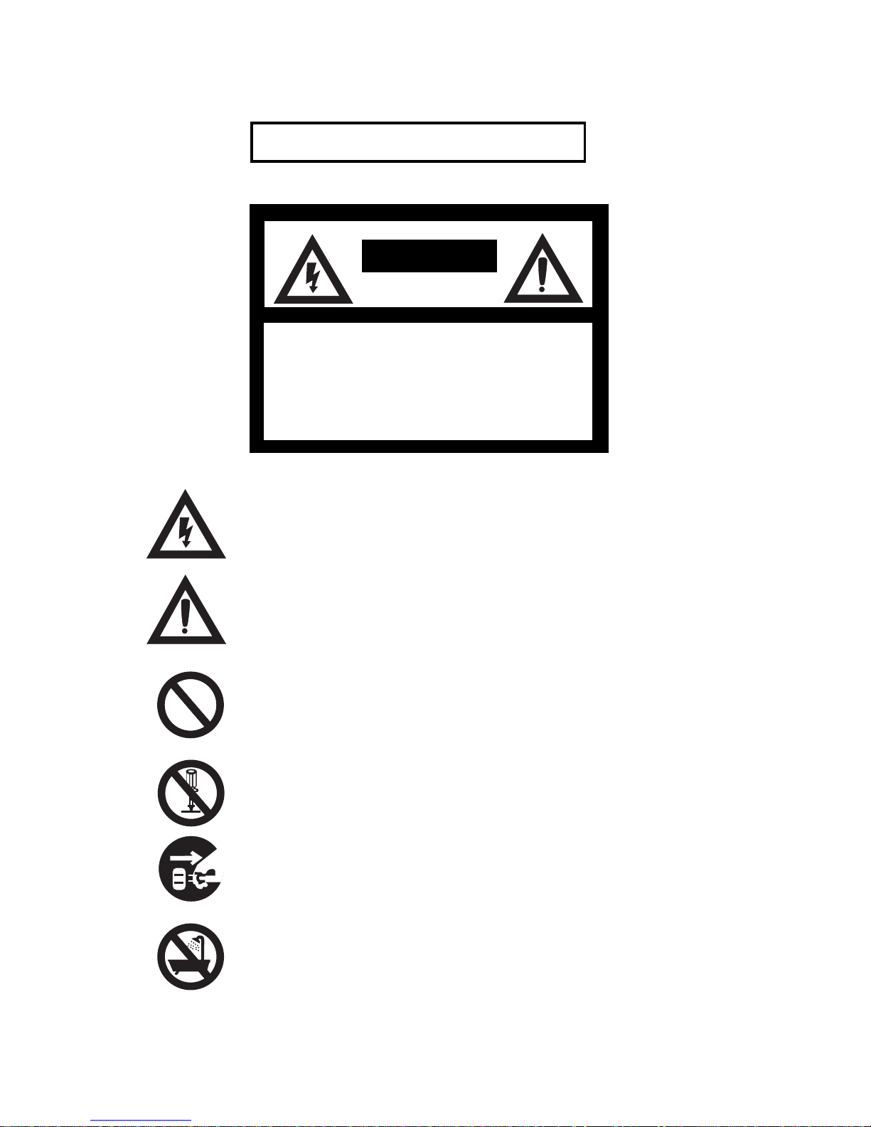
RISK OF ELECTRIC SHOCK
DO NOT OPEN
CAUTION:
TO REDUCE THE RISK OF ELECTRIC
SHOCK, DO NOT REMOVE COVER (OR
BACK), NO USER SERVICEABLE PARTS
INSIDE.
REFER SERVICING TO QUALIFIED SERVICE
PERSONNEL.
The lighting flash with arrowhead symbol, within an equilateral triangle, is
intend to alert the user to the presence of uninsulated ”dangerous voltage”
within the product’s enclosure that may be of sufficient magnitude to
constitute a risk of electric shock to persons.
The exclamation point within an equilateral triangle is intended to alert the
user to the presence of important operating and maintenance (servicing)
instructions in the literature accompanying the appliance.
The slash within a circle is intended to alert the user to the presence of
prohibition of any kind of operation, maintenance and storage.
The abstraction within a circle is intended to alert the user to presence of
prohibition to disassemble the product’s.
The abstraction within a circle is intended to alert the user to power off the
product’s and to take off the plug.
The abstraction within a circle intended alert the user to presence of
prohibition to expose the product’s to rain, moisture or any kind
of wet place.
CAUTION
Do not attempt to disassemble this camera.
Precautions
Model Name :
To prevent electric shock, do not remove cover. There are no userserviceable parts inside. Refer servicing to qualified service
personnel.
Do not expose this camera to rain or moisture.
Do not face this camera towards the sun, extreme
bright light or light reflecting objects.
Even when this camera is not in use, put the supplied shade-cap on
the camera head.
Handle this camera with the maximum care.
Operate this camera only from the type of power
source indicated on the camera.
Power off the camera during any modification such as changes of
jumper-line and jumper-register.
USER’S RECORD
The production serial number are
shown on the bottom of camera
Serial No. :
Typical CCD Characteristics
The following effects may be observed on the video monitor screen do not indicate any fault of
the CCD camera, but do associate with typical CCD characteristics.
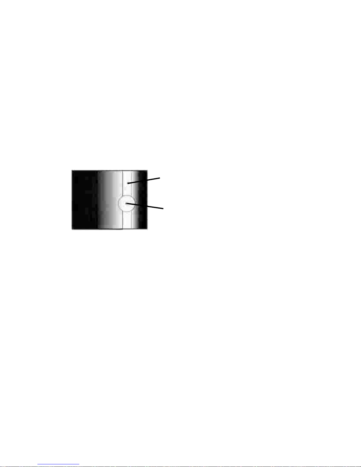
Due to an excessive bright object such as electric lighting, sun or strong re flection,
vertical smear may be visible on the video monitor screen. This phenomenon is related to
the characteristics of Interline Transfer System employed in the CCD.
When the CCD camera shoots a dark object at high temperature, fixed pattern noise
(dots) may be appeared over the entire area of the video monitor screen.
V. Smear
Vertical Smear
Excessive bright object
Video monitor screen
When the CCD camera shoots stripes, straight lines or similar patterns, jagged image on
the monitor may be appeared.
V. Aliasing
Blemishes
An array of individual sensor elements (pixel) in the CCD image sensor may consist of
blemish, although it is not a problem in practical
operation.
Patterned Noise
«
«
«
«

1. General.............................................................................................
3. Main Features ............................................................................... .
5. Pin Assignment
5-1. 12P Multi connector ......................................................... .
5-2. 6P Multi connector......................................................... ..
5-3. 9P D.sub connector .........................................................
6. Functions and Operations
6-1. Input/Output of HD/VD signal................................................
7. Mode Setting
7-1. SW1 switch on the rear panel...............................................
7-2. Other switches/jumpers on board.......................................
8. External Appearance....................................................................
9. Specifications.................................................................................
a) Input of External HD/VD signal..................................................
b) Output of Internal HD/VD signal................................................
1
2
4
5
6
7
7
7
14
16
19
20
Table of Contents
3. Standard Composition................................................................. . 1
4. Locations and Functions............................................................... 3
6-2. External Trigger Mode...........................................................
a) Random trigger Mode - 1..........................................................
b) Random trigger Mode - 2...........................................................
7
8
10
c) Long Time Exposure Mode........................................................
12

CV-M90 (Rev.c) is a 3CCD RGB color camera exclusively designed for
machine vision and image processing applications where excellent resolution, high fidelity color-reproduction and advanced electronic shutter
capability are required.
3CCD C-mount optical prism block is newly developed in ultra-compact
size to achieve extended higher resolution compared to RGB output of
the conventional type of 1CCD color camera, and to allow flexible
adaptation of wide variety of C-mount lenses for many optical
requirements.
High speed and asynchronous reset shutter with high quality RGB signal
output offers a perfect result especially in high speed color inspection
applications such as dynamic motion color graphics and superb color
fidelity surveillance.
1. General
1) Camera main body x1
2) Operation Manual x1
Options (Following optical accessories are available upon request.)
1) 12pin Multi connector (HR10A-10P-12S-01)
2) 6pin Multi connector (HR10A-7P-6S)
- 1 -
2. Standard Composition

3 x 1/3” Hyper HAD Interline transfer CCD imager, 768(H) x 494(V) for
NTSC and 752(H) x 582(V) for PAL
Co-site sampling for higher quality color image required in machine
vision and image processing applications
Ultra-compact RGB prism for C-mount
High resolution - horizontal 570 TV lines
Excellent S/N - better than 56 dB
RGB & sync output, RB & G on sync output
Pixel clock, WEN, EEN and HD/VD output for jitter-free image
capturing
High speed asynchronous reset shutter 1/60 up to 1/10000sec.
Long time Exposure Mode - 1/30sec. ~
Easy access to shutter and other functions-mode setting, from rear
panel switch
Internal, External HD/VD synchronization
Compact, light weight, ragged construction with durable connectors
Lens mount - C-mount type
●
●
●
●
●
●
- 2 -
3. Main Features
●
●
●
●
●
●
●
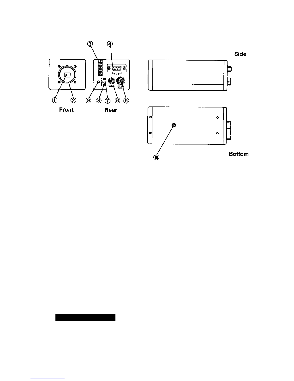
4. Locations and Functions
➀➀
➀➀
➀ CCD Sensor : 1/3“ Hyper HAD Interline transfer CCD sensor
➁➁
➁➁
➁ Lens mount : C-mount type
Note:
Rear protrusion (screw part) of C-mount lens must
be less than 4.1mm (0.16 inch approx.)
➂➂
➂➂
➂ SW1 switch : To set the shutter speed and function modes
➃➃
➃➃
➃ 9-pin Dsub connector : Output RGB Video signal and Sync. signal
➄➄
➄➄
➄ 12-pin Multi connector : Input C+12V power and input/output of
HD/HV signal
➅➅
➅➅
➅ 6-pin Multi connector : Output WEN/EEN signal and input external
trigger pulse
➆➆
➆➆
➆ R Gain Potentiometer : To adjust R Gain manually
➇➇
➇➇
➇ B Gain Potentiometer : To adjust B Gain manually
➈➈
➈➈
➈ One push White-
balance switch : One push switch of white balance
- 3 -
1. It is recommended to use the C-mount lens designed for 3 x CCD color camera
for optimum image quality
Caution on Applicable lens
* Note: 1. To change the signal output on pin no. 6, 7 and 9, it is necessary to make
jumper setting.
See ¨7. Mode Setting¨ for more information
2. Do not input Ext. VD signal at pin no.7 of 12P Multi connector, as it causes
a failure in random trigger mode operation.
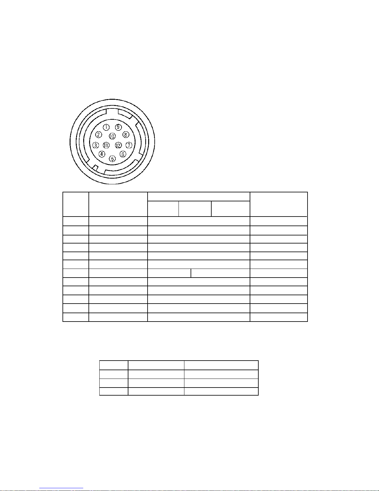
5. Pin Assignment
5-1. 12P Multi Connector (DC IN/SYNC)
HR10A-10R-12PB-01 (Hirose)
- 4 -
GND
DC+12V input
NC
NC
GND
Ext HD input (75
ΩΩ
ΩΩ
Ω)
* See note 2 Ext VD input (75
ΩΩ
ΩΩ
Ω)
GND
NC
GND
DC+12V Input
GND
GND
DC+12V input
NC
NC
GND
Ext HD input (75
ΩΩ
ΩΩ
Ω)
Ext VD input (75
ΩΩ
ΩΩ
Ω)
GND
NC
GND
DC+12V Input
GND
GND
DC+12V input
NC
NC
GND
Int HD output
Int VD output
GND
NC
GND
DC+12V Input
GND
1
2
3
4
5
6*
7*
8
9*
10
11
12
Pin no
Ext.
HD/VD input Mode
(Factory Pre-set)
Random
Trigger-1
Long Time
Exposure
Int.
HD/VD output mode
Pin no.
6
7
9
Factory Pre-set
Ext HD input
Ext VD Input
NC
Others
Int HD output
Int VD output
Pixel clock output
Random
Trigger-2
Ext. Trigger mode
 Loading...