

Page 1

CV-M77
Progressive Scan Camera
CV-M77
Operation Manual
Camera: Revision A
Manual: Version 1.0
- 1 -
Page 2
CV-M77
- 2 -
Page 3

CV-M77
1 General...................................................................................................................... 5
2 Standard Composition............................................................................................. 5
3 Main Features ........................................................................................................... 5
4 Camera Housing and Dimensions .......................................................................... 6
5 Pin Assignment ........................................................................................................ 7
5.1 12-pin Multi-connector (DC-IN/SYNC.).................................................................................... 7
5.2 6-pin Multi-connector (RS 232C/TRIGGER)............................................................................ 7
5.3 9-pin DSUB-connector (RGB/SYNC.) .....................................................................................8
5.4 Input and Output Circuits.........................................................................................................9
5.4.1 Video input ...........................................................................................................................9
5.4.2 Trigger input ........................................................................................................................ 9
5.4.3 HD and VD input ..................................................................................................................9
5.4.4 HD, VD, PCLK, WEN and EEN output .................................................................................... 9
6 Functions and Operation....................................................................................... 10
6.1 Input/Output of HD/VD Signal................................................................................................ 10
6.1.1 Input of External HD/VD signals......................................................................................... 10
6.1.2 Output of Internal HD/VD signals....................................................................................... 10
6.2 Continuous operation ............................................................................................................10
6.3 External Trigger Mode...........................................................................................................10
6.3.1 Edge Pre-select Trigger Mode ........................................................................................... 10
6.3.2 Pulse Width Control Trigger Mode..................................................................................... 11
6.3.3 Frame-delay Readout Mode ..............................................................................................12
6.3.4 Long Time Exposure Mode................................................................................................ 12
6.4 Timing diagram for Horizontal and Vertical Sync. Video Output ...........................................13
6.5 Timing diagram for Edge Pre-select mode............................................................................14
6.6 Timing diagram for Pulse Width Control mode...................................................................... 14
6.7 Timing diagram for Frame-delay Readout mode................................................................... 14
6.8 Timing diagram for Long Time Exposure mode ....................................................................15
7 Configuring the camera using the serial interface. ............................................. 16
7.1 Mode Setting using ASCII commands via the RS-232C port. ............................................... 16
7.2 Communication setting.......................................................................................................... 16
7.3 Command Protocol................................................................................................................16
7.3.1 Receiving Data (Camera->PC) .......................................................................................... 17
7.4 RS232C Cable Connections.................................................................................................. 18
8 Switch Settings ...................................................................................................... 19
8.1 Mode Settings by Switch ....................................................................................................... 19
8.2 Signals by Switch Settings ....................................................................................................19
8.2.1 SW301 switch ....................................................................................................................19
8.2.2 SW302 switch ....................................................................................................................20
8.2.3 SW303 switch ....................................................................................................................20
9 Jumper settings ..................................................................................................... 21
9.1 Jumper locations ...................................................................................................................21
9.2 Jumper table.......................................................................................................................... 22
10 CV-M77 Camera Control Tool................................................................................ 23
11 Specifications ......................................................................................................... 25
11.1 Spectral sensitivity .............................................................................................................26
12 Appendix ................................................................................................................. 27
12.1 Precautions ........................................................................................................................ 27
12.2 Typical CCD Characteristics ..............................................................................................27
12.2.1 Smear .............................................................................................................................27
12.2.2 Aliasing ...........................................................................................................................27
12.2.3 Blemishes .......................................................................................................................27
- 3 -
Page 4

CV-M77
12.2.4 Patterned Noise .............................................................................................................. 27
12.3 References......................................................................................................................... 27
13 Users Record .......................................................................................................... 28
14 Index........................................................................................................................ 28
- 4 -
Page 5

CV-M77
1 General
The CV-M77 camera is a compact RGB color progressive scan camera designed for automated
imaging applications. The 1/3" CCD sensor with square pixels and primary mosaic filter offers a
superb image quality and the build in DSP assures high color reproduction.
The camera incorporates several triggered modes and various shutter functions to capture moving
objects and to control the light. All camera mode settings can be controlled via an RS-232C
interface or by the switch at the rear of the camera.
The CV-M77 camera is ideal for demanding color applications such as color inspection, gauging
and color printing.
The latest version of this manual can be downloaded from:
The latest version of the Camera Control Tool software can be downloaded from:
www.jai.com .
www.jai.com .
2 Standard Composition
The standard camera composition consists of the camera main body and the operation manual.
3 Main Features
• New 1/3” full frame progressive scan interline transfer CCD
• RGB Primary color mosaic filters on chip
• 1034 (h) x 779 (v) 4.65µm square pixels (1024 x 768 pixels read out) – XGA format
• 25 full frames RGB video output per second
• Internal, external HD/VD or random trigger synchronization
• Edge pre-select and pulse width controlled external trigger modes
• Programmable shutter speed from 1.5 H to 791 H
• Long time exposure with external VD pulse interval
• Frame delay readout for edge pre-select and pulse width controlled shutter
• Exposure enable EEN, write enable WEN and pixel clock output
• Short ASCII commands for fast mode setup via serial port
• Windows Camera Control Tool software to setup the camera via RS 232C
• Pixel clock output optional
- 5 -
Page 6
CV-M77
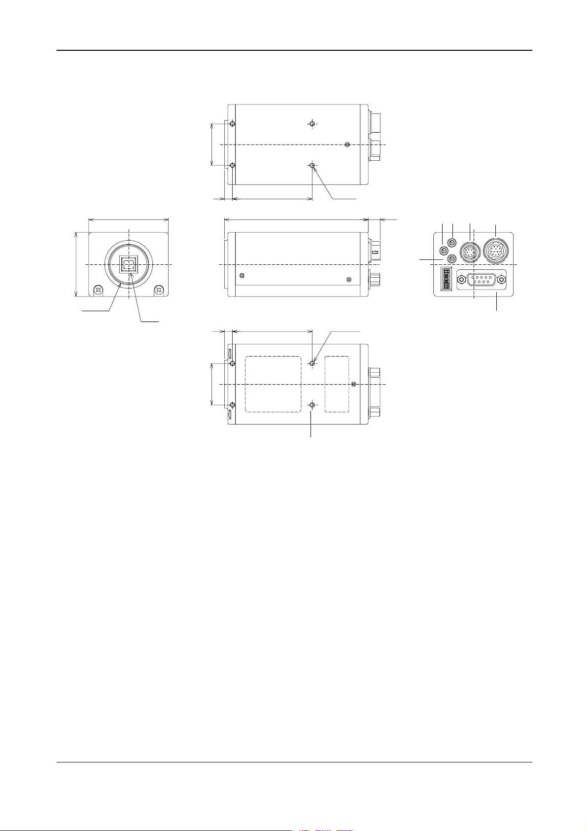
4 Camera Housing and Dimensions
26
(1.02)
40
1
(C-Mount)
(1.57)
50
(1.97)
2
(CCD chip)
5
(0.2)
5
(0.2)
26
(1.02)
50
(19.7)
90
(3.54)
50
(19.7)
Figure 4-1
11
4-M3 depth5
4-M3 depth5
7.6
(0.3)
6
5
3
R
MG
SW1
B
RS-232C
4
TRIG
RGB
7
IN
DC
SYNC/
8
1 Lens mount of C-mount type. *1)
2 1/3" interline transfer CCD progressive scan sensor with square pixels and
primary mosaic filter
3 R Gain Potentiometer. To adjust Red gain level manually.
4 B Gain Potentiometer. To adjust Blue gain level manually.
5 MG Gain Potentiometer. To adjust Master gain level manually.
6 6 pin connector for RS 232C signals, input of ext. trigger pulse and WEN output.
7 12 pin connector for +12V DC power and HD/VD input/output.
8 9 pin D-Sub connector for RGB video output, video synchronization output and
pixel clock output.
9 Switch to set shutter speed and function mode.
10 Screw holes for tripod mounting plate (optional plate)
11 4 M3 mounting threads. *2)
*1) Note: Rear protrusion on C-mount lens must be less than 6mm (0.24-inch approx.)
*2) Note: Notice depth of thread is only 5mm. Too long screws may harm inside electronics.
- 6 -
Page 7
CV-M77
5 Pin Assignment
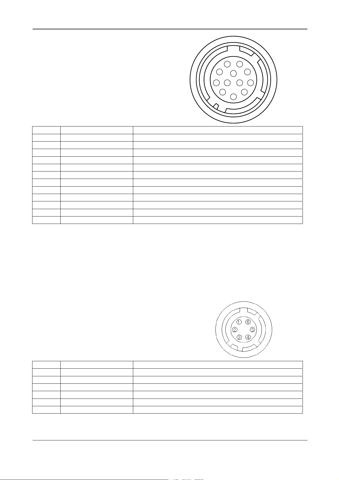
5.1 12-pin Multi-connector (DC-IN/SYNC.)
Type: HR10A-10R-12PB-01 (Hirose male)
Seen from rear.
2
3
4
Pin No. 5.1.1.1 Signal 5.1.1.2 Remarks
1
2
3
4
5
6*
7*
8
9*
10*
11*
12
5.1.1.3 GND
+12V DC input
GND
NC
GND
Ext.HD input
Ext.VD input
GND
NC
WEN
Ext. trigger
GND
SW-S301.1 “ON” for 75Ω termination, SW-S303.1 “OFF” for HD output
SW-S301.2 “ON” for 75Ω termination, SW-S303.2 “OFF” for VD output
PCLK out: JP305 “short”, JP306 “open”
NC: JP309 and JP310 “open”. GND: JP308 “open” JP309 and JP310 “short”
NC: JP401 and JP301* “open”. +12V DC JP401 “short” and JP301* “open”
Notes:
*) Signals on pin no. 6, 7,9,10 and 11 can be changed by jumper setting.
See section 8 “Switch Settings” and section 9 “Jumper Settings ” for more information.
*) In Edge Pre-select and Pulse Width Control mode do not input ext. VD signal.
*) When using the HD/VD, PCLK and WEN signals (input or output) from the 12-pin
connector do not use the same signals (input or output) from the 9 pin D-SUB connector.
*) JP301 is “short” by a capacitor (factory setting – see section 9 “Jumper Settings”.
*) Signals shown in bold italics are factory settings.
5.2 6-pin Multi-connector (RS 232C/TRIGGER)
Type: HR10A-7R-6PB (Hirose male)
Seen from rear.
11
9
1
8
10
7
12
6
5
Pin No. 5.2.1.1 Signal 5.2.1.2 Remarks
1
2
3
4*
5
6*
TXD (RS-232C)
RXD (RS-232C)
GND
NC
Ext.TRIG input
EEN output
GND: JP402 “short”
WEN out: JP312 “open” and JP311 “short”
Notes:
*) Signals on pin no. 4 and 6 can be changed by jumper setting.
- 7 -
Page 8
CV-M77
See section 8 “Switch Settings” and section 9 “Jumper Settings ” for more information.
*) When using the WEN signal from the 6 pin connector do not use the same signal from the
9 pin connector.
*) Signals shown in bold italics are factory settings.
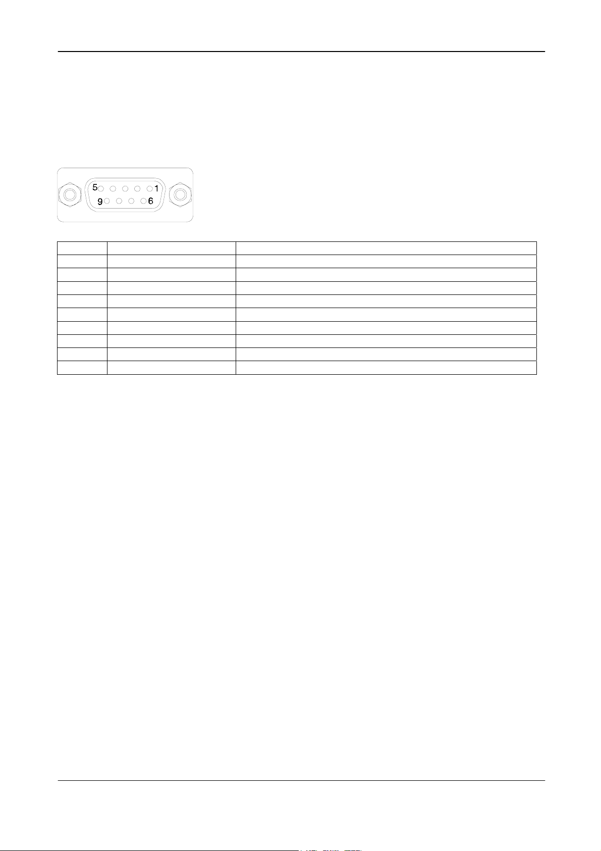
5.3 9-pin DSUB-connector (RGB/SYNC.)
Pin No. 5.3.1.1 Signal 5.3.1.2 Remarks
1*
2
3
4*
5
6*
7*
8
9*
NC
GND
R output
G output
B output
HD input
Sync output
GND
NC
Notes:
*) Signals on pin no. 1,4, 6,7 and 9 can be changed by jumper setting.
See section 8 “Switch Settings” and section 9 “Jumper Settings ” for more information.
*) In Edge Pre-select and Pulse Width Control mode do not input ext. VD signal.
*) When using the HD/VD, PCLK and WEN signals (input or output) from the 9-pin D-SUB
connector do not use the same signals (input or output) from the 12 pin or 6 pin
connectors.
*) Signals shown in bold italics are factory settings.
VD input: JP303 “open” and JP304 “short”
Sync. on G: SW302-3 “ON”
HDinput: SW303-1 “ON”. HDout: SW303-1 “OFF”
WEN output: SW302-4 “ON”
PCLK output: JP305 “open” and JP306 “short”
- 8 -
Page 9
CV-M77
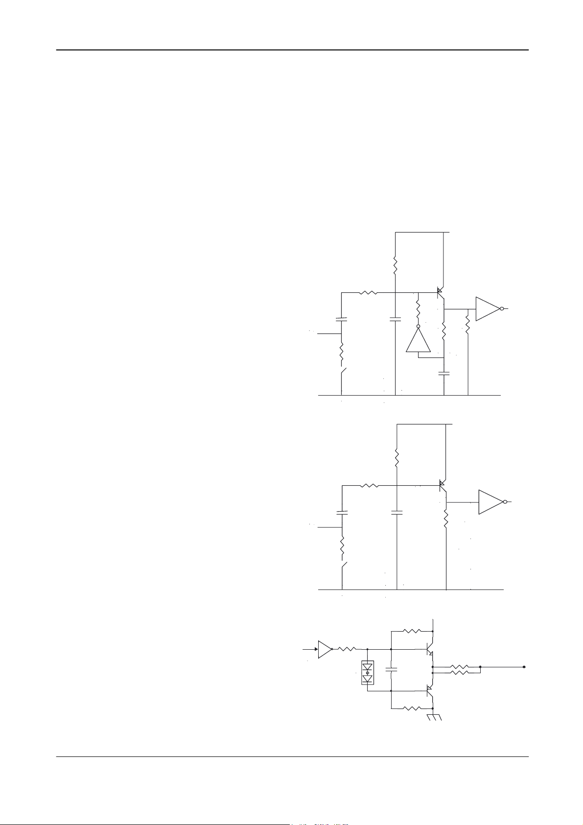
5.4 Input and Output Circuits
In the following schematic diagrams the input and output circuits for video and timing signals are
shown. For alternative connections refer to “Internal Switch and Jumper Settings”. Jumper
settings are shown as for factory default.
5.4.1 Video input
The video output signal is a 75Ω RGB video
signal. The signal level is 0.7Vpp.
Composite sync. is selectable on the green
video signal via software or the internal switch
302-3. The sync. signal level is 0.3Vpp.
5.4.2 Trigger input
The trigger input is AC coupled with a flip-flop.
The input signal level is 4V ± 2V.
The trigger input impedance is 1.2 kΩ or 75Ω
selectable via the internal switch S301-3.
Trigger input
SC104V
75C
SC102V
+5V
33KB
33KB
1K8B
100KB
5.4.3 HD and VD input
The HD and VD input circuit can be 75Ω
terminated via the internal switch S301-1 and
S301-2.
The input signal level is 4V ± 2V.
5.4.4 HD, VD, PCLK, WEN and EEN output
The output circuits for these signals are 75Ω
complementary emitter followers. The single
circuit delivers a TTL signal. The output level
≥ 4 V from 75Ω (no termination).
HD, VD
input
TTL
S301-3
SC104V
75C
S301-1(HD),2(VD)
220B
SC102V
33KB
10KB
SC102V
1K8B
+5V
+5V
120C
150C
GND
GND
Int VD
Int HD
PCKL
WEN
EEN
10KB
- 9 -
Page 10

CV-M77
6 Functions and Operation
Apart from the standard continuous operation, the CV-M77 features three external triggering
modes, Edge Pre-select, Pulse Width Control mode and Readout Delay mode. These 3 external
triggering modes operate with H non-reset. In H non-reset, the exposure will be synchronized to
the internal HD and the exposure will start at the first HD after the negative going edge of the
trigger (see figure 6-1).
EDGE PRE-SELECT
H non-reset
Figure 6-1: H non-reset relation
Trigger
int. HD
Exposure
shutter time
Read out
6.1 Input/Output of HD/VD Signal
6.1.1 Input of External HD/VD signals
This setting is factory pre-set. The video output is synchronized with external HD/VD signals if
applied. If no ext. HD signal is input the camera will switch to the internal X-tal controlled HD sync.
If no ext. VD is connected the camera will continue with its internal VD.
The external HD/VD signal is factory preset to TTL signals (2.0-5.0V). The external HD/VD signals
can be 75 ohm terminated by setting the S301-1,2 switches on the PK 8308 board to ON (see
switch settings) – the signal input level is then 4.0 Vp-p ±2.0V.
6.1.2 Output of Internal HD/VD signals
In order to output internal HD/VD signals the S303-1,2 switches on the PK 8308 board have to be
set to OFF. The output can be either TTL level or from a 75Ω source by setting the proper S301
switches on the PK 8308 board to OFF or ON (see switch settings).
6.2 Continuous operation
For applications that do not require asynchronous external trigger but run in continuous operation
this mode is used. On the camera rear panel SW1-5 to SW1-7 are set to OFF for normal internal
trigger mode. The shutter time (the exposure time) is selected by SW1-1 to SW1-4. The mode
setting and the shutter setting can be done via RS 232C control.
6.3 External Trigger Mode
The CV-M77 camera features 3 external triggering modes:
1 Edge Pre-select mode. (Asynchronous reset and exposure start by an ext. trigger pulse)
2 Pulse Width Control mode. (Exposure control by the low period of the ext. trigger pulse)
3 Readout Delay mode. (The readout is controlled by the ext. trigger and an ext. VD signal)
For all three triggering modes the exposure will start at the next internal HD as explained above (H
non-reset). The trigger input can be TTL level or 75 ohm terminated by setting the specific S301
switch on the PK 8308 board to OFF or ON (see switch settings). When 75 ohm terminated the
signal input level is 4.0 Vp-p ±2.0V.
6.3.1 Edge Pre-select Trigger Mode
This trigger mode operates in H non-reset mode. In H non-reset mode the exposure will start at
the first internal HD after the trigger. The trigger input should be longer than or equal to 2 HD (102
µsec.) and shorter than 1msec. The external trigger pulse initiates the capture, and the exposure
- 10 -
Page 11

CV-M77
time (accumulation time) is governed by the fixed shutter speed set up by the rear panel DIPswitches or via RS-232C control. The resulting video signal will start to be read out after the
selected shutter time. The WEN pulse indicates the start of valid video signal. Refer to timing
charts for details. A new trigger pulse must not be applied before the video read out has finished. If
the camera is synchronized to an external HD signal, there are some requirements to the phase
between the ext. HD and the Ext. trigger. The falling edge of the trigger should be less than 8 µsec
before the falling edge of the ext. HD and less than 2 µsec after the falling edge of the ext. HD (see
figure 6-2). Otherwise the jitter will be too high.
To use this mode:
Set SW1-5,6 and to SW1-7 on the rear plate of the camera to “OFF” or use the RS 232C control.
CV-M77 Input Signal Phase Relation
Phase Relation of TRIG and EXTHD
TRIG
EXTHD
AB
A=Less than 8µs
B=Less than 2µs
A
B
Phase Relation of EXTVD and EXTHD
EXTVD
EXTHD
B
B=Less than 42µs
Figure 6-2: Input signal phase relation
6.3.2 Pulse Width Control Trigger Mode
This trigger mode where the length of the trigger pulse determines the exposure time operates in H
non-reset mode. In H non-reset mode the trigger pulse and the HD signal are synchronized. The
exposure will start at the first HD pulse after the falling edge of the external trigger signal. The
exposure ends at the rising edge of the external trigger signal. The trigger pulse must be longer
than >1H (51µsec) and shorter than 2000 H. To avoid jitter the camera should be synchronized to
an external HD. There are some requirements to the phase between the ext. HD and the Ext.
trigger. The falling edge of the trigger should appear in the interval less than 8 µsec before the
falling edge of the ext. HD and less than 2 µsec after the falling edge of the ext. HD and the rising
edge off the trigger should be fall in the interval 8 µsec before the rising edge of the ext. HD and 2
µsec after rising edge of the ext. HD. (See figure 6-2).
The resulting video signal will start to be read out after the rising edge of the external trigger signal.
The WEN pulse indicates the start of valid video signal. Refer to timing charts for details.
A new trigger pulse must not be applied before the video read out has finished.
To use this mode:
C
C=More than 0.5
µs
- 11 -
Page 12

CV-M77
Set SW1-5 and SW1-6 on the rear plate of the camera to “ON” and SW1-7 to OFF or use the RS
232C control to set-up the PWC mode of the camera.
6.3.3 Frame-delay Readout Mode
This trigger mode operates in H non-reset mode. In H non-reset mode the trigger and HD is
synchronized. The exposure will start at the first HD pulse after the falling edge of the external
trigger signal. The exposure ends at the rising edge of the external trigger signal. The trigger pulse
must be longer than >1H. To avoid jitter, the camera should be synchronized to an external HD.
There are some requirements to the phase between the ext. HD and the Ext. trigger. The falling
and rising edge off the trigger should be within 8 µsec. before the falling and rising edge of the ext.
HD pulse and not later than 2µsec after the falling and rising edge of the HD pulse (see fig. 6.3)
The resulting video signal will first start to be read out after the input of an external VD signal. The
readout delay should not be to long due to visible dark current noise generated in the CCD sensor.
The WEN pulse indicates the start of valid video signal. Refer to timing charts for details.
A new trigger pulse must not be applied before the video read out has finished.
To use this mode:
Set SW1-5 to SW1-7 on the rear plate of the camera to “ON” or use the RS 232C control to set-up
the Frame-delay Readout Mode of the camera.
6.3.4 Long Time Exposure Mode
The exposure time is the interval between 2 ext. VD pulses sent to the VD input of the camera.
The exposure starts after input of the first ext. VD pulse, and ends after the next input of the ext.
VD pulse, which again starts a new exposure.
The long time exposure is a continuous process where each external VD pulse will synchronize the
camera, stop on exposure, start a new exposure and read out the previous accumulated signal.
The exposure can be selected in intervals of complete vertical timing periods (=792H)
This long time exposure mode operates in H non-reset mode. In H non-reset mode the external VD
signal and the internal HD signal are synchronized. The exposure will start at the first HD pulse
after the falling edge of the external trigger signal. Se figure 6-2 for the phase relationship between
ext. HD and ext. VD pulses.
To use this mode:
Set SW1-1 to SW1-7 on the rear plate of the camera to OFF or use the RS 232C control. Apply
the continuous external VD signal.
- 12 -
Page 13

CV-M77
6.4 Timing diagram for Horizontal and Vertical Sync. Video Output
- 13 -
Page 14

CV-M77
6.5 Timing diagram for Edge Pre-select mode
TRIG
EXT HD
INT HD
INT VD
EEN
Exposure time
WEN
Video out
2H Min
1.5H-2.5H
0.5H
9H
17H
4H
770H
Effective video
6.6 Timing diagram for Pulse Width Control mode
TRIG
1H-2000H
EXT HD
1H=50.8µs
2H Min
1.5H-2.5H
Exposure time
4H
0.5H
1H=50.8µs
1H Min
INT HD
INT VD
0.5H-1.5H
9H
EEN
Exposure time
WEN
0.5H
17H
4H
Video out
770H
Effective video
6.7 Timing diagram for Frame-delay Readout mode
TRIG
EXT HD
INT HD
EXT VD
INT VD
EEN
Exposure time
WEN
Video out
1H-2000H
0.5H
Delay time
1H
17H
4H
770H
Effective video
0.5H-1.5H
Exposure period
4H
0.5H
‚P‚g ‚T‚OD‚WƒÊ‚“
1H Min
0.5H
4H
- 14 -
Page 15

CV-M77
6.8 Timing diagram for Long Time Exposure mode
EXT HD
INT VD
1H=50.8µs
EXT VD
INT VD
EEN
WEN
Video out
1H Max
1V x N (2VD Min)
9H
17H
Exposure time
4H
770H
Remarks:
1VD indicates 792H.
The interval of EXT VD input has to be multiple number of 1VD.
EEN is lov
4H
1H Max
- 15 -
Page 16

CV-M77
7 Configuring the camera using the serial interface.
7.1 Mode Setting using ASCII commands via the RS-232C port.
The configuration of the CV-M77 camera can be done via the RS-232C port. The camera is to be
set up via an ASCII terminal or from a PC running terminal emulator software.
Below is the description of the ASCII based short command protocol.
The RS-232C serial interface specification for CV-M77 is:
7.2 Communication setting
Baud Rate 9600bps
Data Length 8bit
Stop Bit 1bit
Parity Non
Xon/Xoff Control Non
7.3 Command Protocol
Command Name Format Parameter Remarks
A - General settings and useful commands.
0=Echo off
1 Echo back EB=[Param.]<CR><LF>
Firmware program
2
version request
B - Timing and shutter related commands.
1 Shutter mode
2 Shutter speed
Programmable
3
exposure
4 Trigger mode
5 Wen polarity
6 G on SYNC
7 EEN polarity
8 WEN/Sync switch
VN?<CR><LF>
SM=[Param.]<CR><LF>
SM?<CR><LF>
SH=[Param.]<CR><LF>
SH?<CR><LF>
PE=[Param.]<CR><LF>
PE?<CR><LF>
TR=[Param.]<CR><LF>
TR?<CR><LF>
WP=[Param.]<CR><LF>
WP?<CR><LF>
SY=[Param.]<CR><LF>
SY?<CR><LF>
EP=[Param.]<CR><LF>
EP?<CR><LF>
WS=[Param.]<CR><LF>
WS?<CR><LF>
1=Echo on
Set to 'off' when power is on.
0=Normal
1=Programmable exposure
0=OFF(1/25), 1=1/50, 2=1/125,
3=1/250, 4=1/500, 5=1/750,
6=1/1000, 7=1/1500, 8=1/2000,
9=1/3000, 10=1/4000, 11=1/10000
3-791
(1/10000s - 1/25s in 1HD
increments)
3= 1.5H(0.076ms)
4= 2.5H(0.127ms)
:
791=789.5H(40.107ms)
0=Normal
1=Edge pre-select
2=Pulse width control
3=Frame delay readout
4=Long time shutter
5=PWC delay readout
0=Active_L, 1=Active_H
0=OFF, 1=ON
0=Active_L, 1=Active_H
0=WEN, 1=Sync
Response is 3 letter
(ex) 100
Available when SM=0 and
TR=0 or 1or 3.
Available when SM=1 and
TR=0 or 1 or 3.
- 16 -
Page 17

CV-M77
C - Gain and analogue signals settings.
1 AGC switch
2 Master gain level
3 Red gain level
4 Blue gain level
5 AGC level
6 White balance
7 Auto white balance AW=[Param.]<CR><LF> 0=One push auto white balance Available when WB=1.
8 Master setup level
9 Red setup level
10 Blue setup level
11 White clip level
12 Gamma select
D - saving and loading data in EEPROM
Load settings
(from camera
1
EEPROM)
Save settings
2
(to camera EEPROM)
Save settings into
3
Factory Area.
EEPROM Current
4
Area No. Request
7.3.1 Receiving Data (Camera->PC)
If the function succeeds, the return value is a handle to the newly allocated memory object. If the
setting succeeds, returned is the below word from the camera.
COMPLETE<CR><LF>
Error Messages:
• Command Error:
01 Unknown Command!!<CR><LF>
• Parameter Error:
02 Bad Parameters!!<CR><LF>
Response to Request Command
Example:
Request Command (PC→Camera)
Command Name Format
Trigger Mode TR?<CR><LF> TR=[Param.]<CR><LF>
AS=[Param.]<CR><LF>
AS?<CR><LF>
GA=[Param.]<CR><LF>
GA?<CR><LF>
RG=[Param.]<CR><LF>
RG?<CR><LF>
BG=[Param.]<CR><LF>
BG?<CR><LF>
AG=[Param.]<CR><LF>
AG?<CR><LF>
WB=[Param.]<CR><LF>
WB?<CR><LF>
SU=[Param.]<CR><LF>
SU?<CR><LF>
RS=[Param.]<CR><LF>
RS?<CR><LF>
BS=[Param.]<CR><LF>
BS?<CR><LF>
WC=[Param.]<CR><LF>
WC?<CR><LF>
GS=[Param.]<CR><LF>
GS?<CR><LF>
LD=[Param.]<CR><LF>
SA=[Param.]<CR><LF> 1=USER DATA AREA
SA00=[Param.]<CR><LF> 0=FACTORY DATA AREA Not disclosed for user.
EA?<CR><LF>
0=OFF (Manual), 1=ON (Auto)
0-700 Available when AS=0.
0-255 Available when WB=0.
0-255 Available when WB=0.
0-255 Available when AS=1.
0=Manual (Variable)
1=Auto (Variable)
2=4600K (Fixed)
3=5600K (Fixed)
33-223
(default = 128)
96-160
(default = 128)
96-160
(default = 128)
0-1023
0=1, 1=0.45, 2=0.6
0=FACTORY DATA AREA
1=USER DATA AREA
0=FACTORY DATA AREA
1=USER DATA AREA
Receiving Data(Camera→PC) Remarks
Sets manual gain values
(RG, BG) when changed
to 0 from other selections.
Latest used DATA AREA
becomes default at next
power up.
"Param." is same as
setting command.
- 17 -
Page 18

CV-M77
Response to firmware version request command
Example:
Request Command (PC→Camera)
Command Name Format
Version Request VN?<CR><LF> ***<CR><LF>
7.4 RS232C Cable Connections
6 PIN
1 TXD
2 RXD
3 GND
4
5
6
Receiving Data(Camera→PC) Remarks
COM PORTCAMERA
9 PIN D
1 CD
4 DTR
6 DSR
2 RXD
3 TXD
5 GND
7 RTS
8 CTS
9 CI
*** is Version No.
(3 letter)
- 18 -
Page 19

CV-M77
8 Switch Settings
Before changing any switch settings or jumper settings turn off the power.
8.1 Mode Settings by Switch
The factory setting for the SW-1 switch on the rear panel of the camera is OFF: The electronic
shutter is OFF, the external trigger modes are OFF, gamma is OFF (=1.0), the AGC is OFF and
the RS-232C control is disabled.
SW 1
OFF
(<)
ON
(>)
OFF (1/25)
1/50
1/125
1/250
1/500
1/750
1/1000
1/1500
1/2000
1/3000
1/4000
Shutter xxxx 1 xxxx < < < < < < < < > > > >
Shutter xxxx 2 xxxx < < < < > > > > < < < <
Shutter xxxx 3 xxxx < < > > < < > > < < > >
Shutter xxxx 4 xxxx < > < > < > < > < > < >
Ext.trigger xxxx 5 xxxx < > > >
Ext.trigger xxxx 6 xxxx < < > >
Frame delay xxxx 7 xxxx < < < >
Normal
Edge
Pre-
Select
Pulse
Width
Control
Read-
Gamma xxxx 8 xxxx 1.0 < > 0.45
Gain xxxx 9 xxxx Manual < > Auto
Control xxxx 10 xxxx Local < > RS 232C
Figure 8-1: Rear plate switch settings
8.2 Signals by Switch Settings
On the PK8308 board inside the camera three switches exist. The switch settings determine
• Termination of external trigger, VD and HD signals
• Color temperature
• Composite sync. on green video signal
• WEN OFF/ON at DSUB connector
• Input/Output of VD and HD signals
8.2.1 SW301 switch
TTL
S301
↔ 75Ω
HD: 1
OFF
Xxxx
VD: 2 Xxxx
TRIG: 3 Xxxx
NC: 4 Xxxx
ON
out
1/10000
Delay
- 19 -
Page 20

CV-M77
The SW301 switches (1-3) in “ON” position activates 75Ω termination of ext.HD and ext.VD signals
and it activates 75Ω termination of an ext.trigger signal. The factory setting is “OFF” enabling TTL
signal termination for all three signals.
8.2.2 SW302 switch
S302
White - 1
OFF
xxxx
Balance 2 xxxx
Sync. on G: 3 xxxx
WEN: 4 xxxx
The SW302 switch has the following functions: The switches (1-2) determines the color
temperature, the switch (3) activates Composite sync. on the green video signal and the switch (4)
outputs the WEN signal at the DSUB connector.
The white balance is dependent on the color temperature of the light. The available settings are:
S302-1 S302-2 Color temperature
OFF OFF 2800-5600K (factory setting)
OFF ON Invalid setting
ON OFF 4600K
ON ON 5600K
The S302-3 switch adds in “ON” position the composite sync. signal to the green video signal. The
factory setting is “OFF” leaving the green RGB signal without sync. signals.
The S302-4 switch outputs in “ON” position the WEN signal via pin 7 of the 9-pin DSUB connector.
The factory setting is “OFF”. In the “OFF” position the camera outputs the composite sync. signal
via pin 7 of the 9-pin DSUB connector.
8.2.3 SW303 switch
S303
output ↔ input
OFF
HD: 1
ON
Xxxxx
VD: 2 xxx
The SW303 switch switches between output of internal HD/VD signals and input of external HD/VD
signals. The factory setting is input of external HD/VD signals (SW303-1 and SW303-2 in “ON”
position). The “ON” position is towards switch SW301.
ON
- 20 -
Page 21

CV-M77
9 Jumper settings
Before changing any switch settings or jumper settings turn off the power.
9.1 Jumper locations
The jumpers are located on two boards, the PK8309A board and the PK8308A board:
JP402
JP401
SC105
1SS302
10K
15K
SC104
SC104
SC104
C3
C3
1SS302
SC105
SC105
EY
100u
2SC3265Y
TK11333BU
D1FS4
S.4
10u
SC103
SC104
SC104
T10/10
KE-10T(1A)
1SS349
1SS349
SC47p
22K
1K
(LA)
680
(BR)
2SA1681
2SC4617R
SC47p
22K
1K
(LA)
680
(BR)
2SA1681
2SC4617R
150K
51K
CHY
SC103
1K
SC103
02CZ7.5Z
2SC4667Y
1K
1K
SC105
7.5Z
1K5
AN8049SH
SC102 SC104
PK8309A
The PK8309A board have two jumpers of interest: JP401 and JP402. Factory setting:
• JP401 and JP402 are “open”.
The PK8308A board has 12 jumpers of interest: JP301-JP312. Factory setting:
• At JP301 is mounted a capacitor to protect the trigger circuit against +12V DC.
• JP303, JP307, JP308, JP309 and JP312 are “short”.
• JP302, JP304, JP305, JP306, JP310 and JP311 are “open”.
- 21 -
Page 22

S
- 22 -
CV-M77
9.2 Jumper table
Jumper settings versus connector pin configuration.
Pin# Function JP301 JP302 JP303 JP304 JP305 JP306 JP307 JP308 JP309 JP310 JP311 JP312 JP401 JP402
12-pin Hirose connector
6 Ext. HD input Short
6 Int. HD output Short
7 Ext. VD input Open Short Open
7 Ext. VD output Open Short
9 NC Open
9 PCLK output Short Open
10 WEN Open Short Short Open
10 NC Open Open
10 GND Open Short Short
11 Trigger Capacitor
11 NC Open Open
11 *) +12V DC Open Short
6-pin Hirose connector
4 NC Open
6 WEN Open Short Open
6 EEN Open Short
9-pin DSUB connector
1 NC Open
1 VD input Open Open Short
4 GND hort
6 HD input Open
6 HD output Open
9 NC Open
9 PCLK output Open Short
NOTE: When using the HD/VD, PCLK and WEN signals (input or output) from the 12 pin connector do not use the same signals (input
or output) from the 9 pin D-SUB connector and vice versa.
*) The external trigger pulse or DC +12V can be input at pin No.11 of the 12 pin Hirose connector by changing the jumper setting on PK8308
and PK8309. A capacitor is mounted at jumper JP301 to avoid feeding the trigger circuit with +12V DC. If this capacitor is removed from JP301
for some reason make sure JP301 is open before feeding the camera with +12V DC at pin No.11 of the 12 pin Hirose connector. *) Greyed out jumper settings are factory settings.
Page 23

CV-M77
10 CV-M77 Camera Control Tool
The Camera Control Tool software for the CV-M77 camera is available from the JAI homepage
(www.jai.com). The software runs under Windows 98, NT and Windows 2000.
The software interface has incorporated all the commands described in the ASCII protocol in an
easy to use fashion – more user-friendly for some than the HyperTerminal or similar programs.
From www.jai.com
Below the different windows are shown.
Control Bar
Windows for all functions
Camera Control Tool software for windows 98/NT/2000 can be downloaded.
- 23 -
Page 24

CV-M77
Fig. Windows from the Camera Control Tools software.
- 24 -
Page 25

CV-M77
11 Specifications
Scanning system Progressive 792 lines 24.8 frames/sec.
Pixel clock 25.000 MHz
Line frequency 19.685 kHz (1270 pixel clock/line)
Frame rate 24.8 frames/sec. (792 lines/frame)
CCD sensor 1/3” RGB primary color IT CCD
Sensing area 4.8 (h) x 3.6 (v) mm
Effective pixels 1034 (h) x 779 (v)
Pixels in video output 1028 (h) x 770 (v)
Cell size
Sensitivity on sensor 1.5 Lux (Max. gain, 50% video)
S/N ratio >50 dB
Video output
Composite sync. on G, 0.3 Vpp (selectable)
Gamma 1.0 – 0.6 – 0.45
Gain
Gain range
Synchronization Int. X-tal. Ext. HD/VD or random trigger
HD sync. input/output
Trigger input
WEN output (write enable)
EEN output (exposure
enable)
Pixel clock output
Composite sync. output
Trigger modes Continuous, Edge pre-select,
Pulse width control (HD non-reset)
Trigger input. (Edge preselect)
Shutter
Programmable exposure 1.5 H to 791 H
Pulse width control 1.5 H to 2000 H
Long time exposure
Frame-delay readout 1 H to 2000 H
Functions controlled by DIP
switch on rear
Functions controlled by
internal DIP switches
Functions controlled by
RS 232C
Communication Baud rate 9600 bps
Operating temperature
Humidity 20 - 80% non-condensing
Storage temp./humidity
Power
Lens mount C-mount
Dimensions 40 x 50 x 90 mm (H x W x D)
Weight 270 g
Note: Above specifications are subject to change without notice.
1/25, 1/50, 1/125, 1/250, 1/500, 1/750, 1/1000,
1/1500, 1/2000, 1/3000, 1/4000, 1/10,000 second
Time from trigger input to ext. VD input.
For Edge pre-select and Pulse width control
Readout mode, Gamma, Gain, Control
HD, VD and Trigger 75 Ω termination on/off
WEN polarity, Sync. on G, White balance
Readout mode, WEN polarity, Sync on G,
Programmable exposure, Gain levels,
White clip, Setup, Gamma, White balance
4.65 (h) x 4.65 (v) µm
RGB video signal, 0.7 Vpp, 75 Ω
Manual – Automatic
-3 to +15 dB
4 V ±2 V, 75 Ω
4 V ±2 V, 75 Ω
4 V ±2 V, 75 Ω
4 V ±2 V, 75 Ω
4 V ±2 V, 75 Ω
4 V ±2 V, 75 Ω
>1 H
2 frames to ∞
Shutter speed, Trigger mode,
VD input/output, HD input/output
Shutter speed, Trigger mode,
-5°C to +45°C
-25°C to +60°C / 20% - 80 %
12V DC ± 10%, 5.5 W
- 25 -
Page 26

11.1 Spectral sensitivity
1.0
CV-M77
0.8
B
G R
IR stop
0.6
0.4
Relative response
0.2
0.0
400 500 600 700 800
Wave l en g th (n m )
- 26 -
Page 27

CV-M77
12 Appendix
12.1 Precautions
Personnel not trained in dealing with similar electronic devices should not service this camera.
The camera contains components sensitive to electrostatic discharge. The handling of these
devices should follow the requirements of electrostatic sensitive components.
Do not attempt to disassemble this camera.
Do not expose this camera to rain or moisture.
Do not face this camera towards the sun, extreme bright light or light reflecting objects.
When this camera is not in use, put the supplied lens cap on the lens mount.
Handle this camera with the maximum care.
Operate this camera only from the type of power source indicated on the camera.
Power off the camera before any modification such as changes of jumper and switch settings are
performed.
12.2 Typical CCD Characteristics
The following effects may be observed on images acquired by CCD cameras. They do not indicate
any fault of the CCD camera function, but associate with typical CCD sensor characteristics.
12.2.1 Smear
Due to an excessive bright object such as car lights, the sun or strong reflection, vertical smear
may be visible. This phenomenon is related to the characteristics of the Interline Transfer System
employed in the CCD.
12.2.2 Aliasing
When the CCD camera captures stripes, straight lines or similar sharp patterns, jagged images
may appear.
12.2.3 Blemishes
12.2.3.1.1.1.1 Some pixel defects can occur. This does in general not have an effect on the practical operation.
12.2.4 Patterned Noise
When the CCD camera captures a dark object at high temperature or is used for long time
integration, fixed pattern noise (shown as bright dots) may appear on the image.
12.3 References
1. This manual and the datasheet for the CV-M77 camera can be downloaded from www.jai.com
2. Camera control software is available from www.jai.com
3. Specifications for the ICX204AK CCD sensor can be found via www.jai.com
- 27 -
Page 28

13 Users Record
Camera type: CV-M77
Revision: (Revision A)
Serial No. ……………..
Users Mode Settings
Users Modifications
14 Index
No index.
CV-M77
- 28 -
 Loading...