

Page 1

Double Speed Progressive Scan CCD Camera
CV-M40
Operation Manual
(Rev.C)
Page 2

CV-M40
DECLARATION OF CONFORMITY
AS DEFINED BY THE COUNCIL DIRECTIVE
89/336/EEC
EMC (ELECTROMAGNETIC COMPATIBILITY)
WE HEREWITH DECLARE THAT THIS PRODUCT
COMPLIES WITH THE FOLLO WING PROVISIONS APPL YING TO IT .
EN-50081-1
EN-50082-1
2
Page 3

CV -M40
Table of Contents
CE declaration ............................................................................................................................. 2
1. General.................................................................................................................................... 4
2. Main features .......................................................................................................................... 4
3. Standard composition............................................................................................................. 4
4. Location and functions ............................................................................................................ 5
5. Pin assignment........................................................................................................................ 6
5-1 12 pin connector (DC IN/SYNC connector) .................................................................... 6
5-2 6 pin connector (TRIGGER connector) .......................................................................... 7
6. Functions and operations ........................................................................................................ 8
6-1 Input/output of HD/VD signal...................................................................................... 8
6-2 Ext. trigger/readout mode ........................................................................................... 8
7. Mode setting......................................................................................................................... 15
7-1 SW1 switch on the rear panel ..................................................................................... 15
7-2 Jumpers on board...................................................................................................... 17
8. External appearance ............................................................................................................. 20
9. Specification ......................................................................................................................... 21
10. Appendix ............................................................................................................................ 22
11. User’s Record...................................................................................................................... 23
3
Page 4

CV-M40
1. General
The CV-M40 is a 1/2” CCD progressive scan camera, incorporating double speed and partial
scan techniques, housed in a compact and robust package.
Using the latest CCD sensor technology with square pixels provides excellent resolution and
signal to noise ratio, together with flexible asynchronous random trigger functions and
multitude of user settings.
2. Main Features
1/2" IT monochrome CCD sensor
654 (h) x 494 (v) x 9.9 µm square pixels (compatible with VGA format)
60 full progressive frames per second over a single video output
120 frames per second using vertical binning (half vertical resolution, pixel aspect ratio 1:2)
Internal, external, HD/VD or random synchronization
3 external trigger/readout modes : Edge pre-select, pulse width and frame-delay readout
Shutter speed 1/125 to 1/12,000
24.5 MHz pixel frequency and 31.468 kHz line frequency
Video output with or without sync.
Set-up by RS 232C or switches
Up to 233 frames per second with partial scan (user selectable)
3. Standard composition
1)
Camera main body
2)
Tripod mount plate (MP-40)
x 1
x 1
3)
Operation manual
Optional accessories
1)2)12 pin connector (HR10A-10P-12S-01)
6 pin connector (HR10A-7P-6S)
x 1
4
Page 5
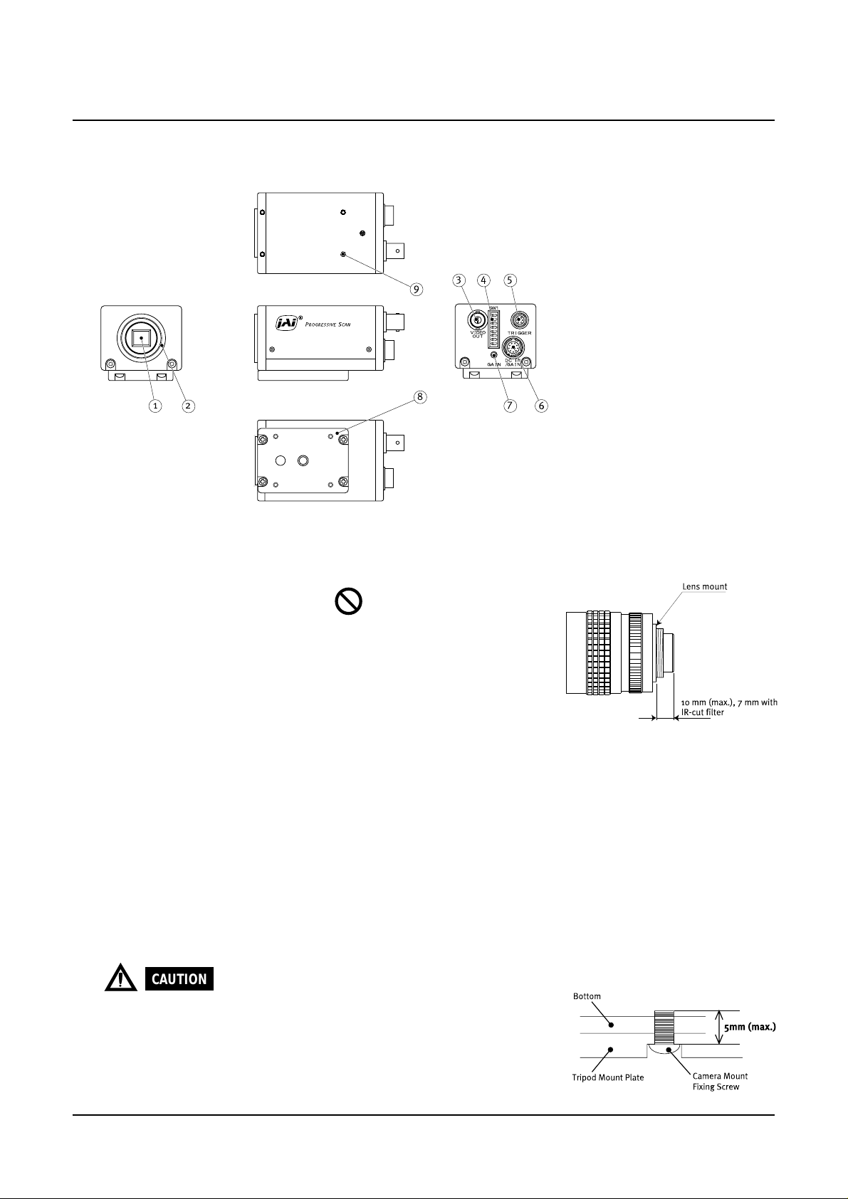
4. Locations and functions
CV -M40
9
3
4 5
1
2
1. CCD sensor
2. Lens mount
3. BNC connector
4. SW1 switch
5. 6 pin multi connector
8
:
1/2 “ IT CCD sensor
:
C-mount type
Note :
Rear protrusion on C-
mount lens must be less
than 10 mm (0.4 inch
approx).
When IR-cut filter is used, it
must be less than 7.0 mm
(0.28 inch approx).
:
Video output (VS 1.0 Vpp at 75 Ohm)
:
Shutter speed and function modes selection
:
RS 232 input and output / ext. trig input
7
6
:
6. 12 pin multi connector
7. Gain potentiometer
+12V DC power / video output / sync. input and output
:
Gain level adjustment
8. Tripod mount plate
9. Screw holes for
Tripod mount plate
CAUTION
When you mount the camera on your system, please make sure to use screws
which have the length less than 5 mm from the camera bottom plate, as it may
cause a serious damage to the PCB inside the camera when the length is
more than 5 mm.
Please be advised that the supplied 4 screws for T ripod mount plate are to be
used exclusively for MP-40, but not for any other mounting adaptor.
5
Page 6
CV-M40
5. Pin assignment
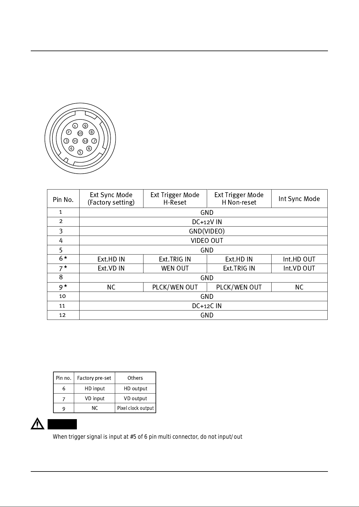
5-1. 12 pin connector (DC IN/SYNC connector)
HR10A-10R-12PB-01 (Hirose) male
Pin No.
Ext Sync Mode
(Factory setting)
1
2
3
4
5
6
7
Ext.HD IN Ext.TRIG IN Ext.HD IN Int.HD OUT
Ext.VD IN WEN OUT Ext.TRIG IN Int.VD OUT
8
9
NC PLCK/WEN OUT PLCK/WEN OUT NC
10
11
12
* Note : To change the signal output on pin no. 6, 7 and 9, it is necessary to make jumper setting.
See “7-2. Jumpers on board” for more informations.
Ext Trigger Mode
H-Reset
DC+12V IN
GND(VIDEO)
VIDEO OUT
DC+12C IN
Ext Trigger Mode
H Non-reset
GND
GND
GND
GND
GND
Int Sync Mode
Pin no. Factory pre-set Others
6 HD input HD output
7 VD input VD output
9NC
CAUTION
1.
When trigger signal is input at #5 of 6 pin multi connector, do not input/output HD signal at #6 of 12 pin multi
connector , as it causes a failure in Ext. trigger mode.
2.
Do not use video output at the same time both from #4 of 12 pin multi connector and BNC connector, as it
causes a failure on video signal due to double termination
Pixel clock output
.
6
Page 7
CV -M40
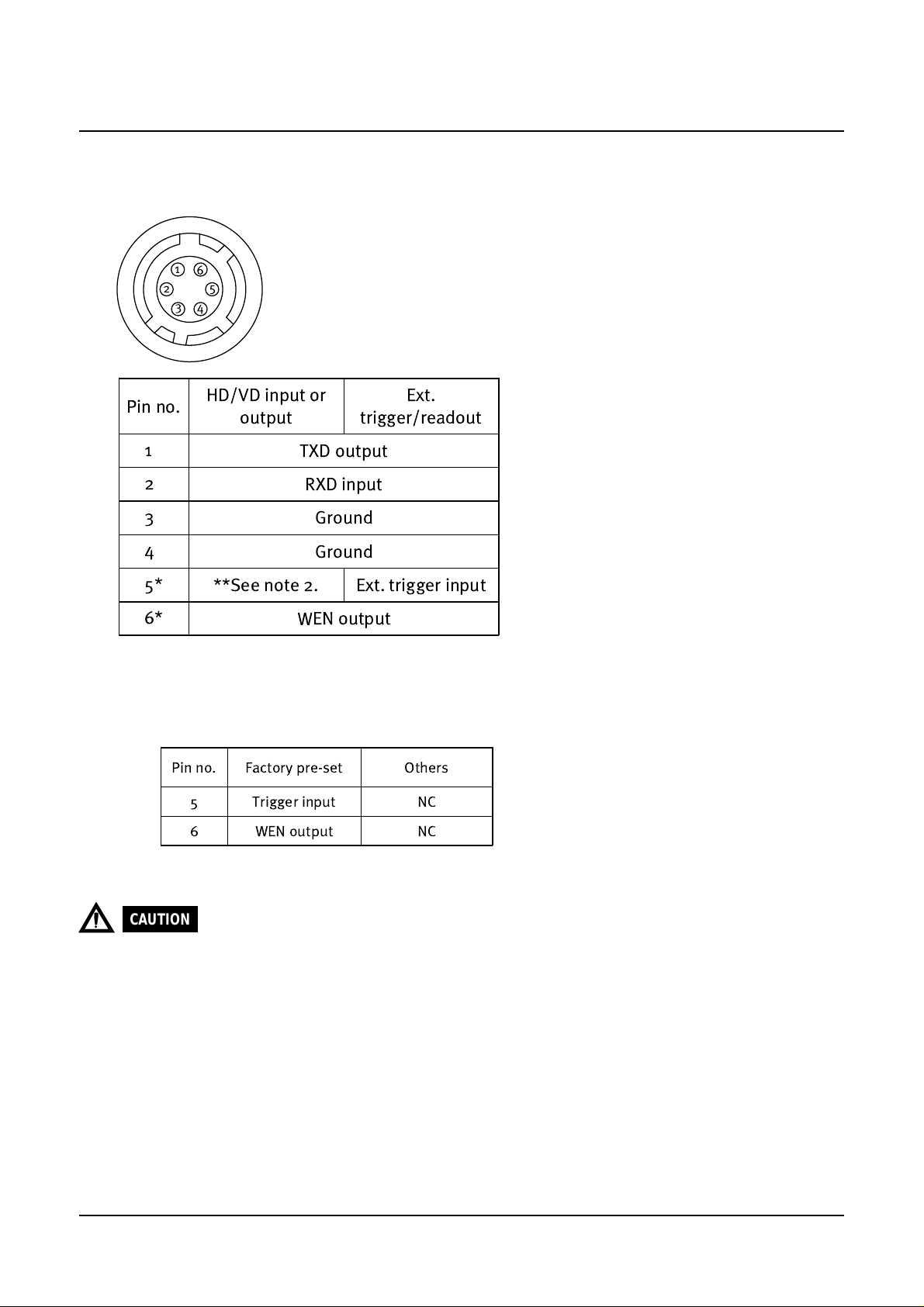
5-2. 6 pin connector (TRIGGER connector)
HR10A-7R-6P (Hirose) male
Pin no.
1
2
3
4
5*
6*
* Note : To change the signal output on pin no. 5 and 6, it is necessary to make jumper setting.
1.
HD/VD input or
output
TXD output
RXD input
Ground
Ground
**See note 2. Ext. trigger input
WEN output
See “7-2. Jumpers on board” for more informations.
Pin no. Factory pre-set Others
5 Trigger input NC
6 WEN output NC
Ext.
trigger/readout
Do not input HD or VD signal at pin no.5, when the camera is set at Continuous mode.2.
CAUTION
When trigger signal is input at #5 of 6 pin multi connector, do not input/output HD signal at #6 of 12 pin multi
connector , as it causes a failure in external trigger mode.
7
Page 8

6. Functions and operations
6-1. Input/output of HD/VD signal
a) Input of external HD/VD signal (Factory pre-set)
To input ext. HD/VD signal, make JP9/JP11 short-circuited, and JP12/JP13 open-circuited.
To change the termination of ext. HD/VD signal, it is neccessary to make the jumper JP8/JP10
short-circuited. All jumpers are located on PK8273 board. For details, please refer to 7-2-
3. Jumpers on PK8273 board.
Note : Factory pre-set is set at HD/VD input (TTL) .
b) Output of internal HD/VD signal
To output int. H D/VD signal, make jumper JP9/J P11 open-circuited, and JP12/JP13 shortcircuited. All jumpers are located on PK8273 board. Please refer to 7-2-3. Jumpers on
PK8273 board.
CV-M40
CAUTION
Int. HD/VD signal is effective only at 75 Ohm termination.
6-2. Ext. trigger/readout mode
Ext. trigger mode of CV-M40 allo ws 3 differ ent driving modes, as follows.
Edge pre-select trigger
mode
Pulse-width control
mode
Frame-delay readout
mode
6-2-1. Edge pre-select mode
Asynchronous reset by the external trigger pulse
:
Exposure period controlled by 8-step fixed shutter steps
Asynchronous reset by the external trigger pulse
:
Exposure period controlled by the pulse width of the external trigger pulse.
:
Asynchronous reset by the external trigger pulse
Exposure period controlled by 8 fixed shutter steps
Video readout timing controlled by rising edge of the external trigger
pulse.
In this mode, the exposure starts at the falling edge of the external trigger pulse. The WEN
pulse originates from the camera.
The shutter speed is controlled by the SW1 switch on the rear panel of the camera and the RS
232C serial interface.
For details, refer to the timing charts section of this manual.
To use this mode, set up the camera as follows ;
8
Page 9

CV -M40
a)
Set SW1-5 at ON, and SW1-6 at OFF to select the Edge pre-select mode.
Set SW1-1 to SW1-3 to select the appropriate shutter speed. For controlling the shutter
b)
speed by the RS 232C serial interface, set SW1-8 at ON.
c)
Set the SW1-4 switch to ON to select the Binning mode and set the switch SW1-7 to OFF
to select the Partial scan mode.
CAUTION
The pulse width of the external trigger pulse must be 2H to 1300H.
6-2-2. Pulse width control mode
In this mode, the exposure time is controlled by the pulse width of external trigger pulse. The
exposure starts at the falling edge of the external trigger pulse and ends at the rising edge of
the external trigger pulse. The WEN pulse is generated and output from the camera.
For details, refer to the timing charts section of this manual.
To use this mode, set up the camera as follows ;
Set SW1-5 at OFF, and SW1-6 at ON to select the Pulse width control mode.
a)
Set the SW1-4 switch to ON to select the Binning mode and set the switch SW1-7 to OFF
b)
to select the Partial scan mode.
CAUTION
The pulse width of the external trigger pulse must be 2H to 525H.
6-2-3. Frame-delay readout mode
In this mode, the timing of the video output is controlled by the width of the external trigger
pulse. The exposure starts at the falling edge of the external trigger pulse and ends according
to the shutter setting. The video signal is output at the rising edge of the external trigger signal.
The WEN pulse is generated and output from the camera.
For details, refer to the timing charts section of this manual.
To use this mode, set up the camera as follows ;
Set SW1-5 at ON, and SW1-6 at ON to select the Frame-delay readout mode.
a)
Set SW1-1 to SW1-3 to select the shutter speed.
b)
Set the SW1-4 switch to ON to select the Binning mode and set the switch SW1-7 to OFF
c)
to select the Partial scan mode.
CAUTION
The minimum value of pulse width for the external trigger pulse depends on the exposure time, as follow.
Minimum : pulse width (more than 3H) > exposure time
9
Page 10

6-2-4. Timing charts
1. Video out (H)
Ext.HD
Int.HD
WEN
(Positive/Negative)
Int.VD
Video out
3.78
s 20ns
700ns
CV-M40
Note:1ck=40.7nsec
780ck
100ns
18ck 54ck60ck
2.Ext. sync mode
2-a) Normal readout(1/60sec.1frm=525H,60frm/sec.)
Ext.HD
Ext.VD
VIDEO OUT
WEN(positive)
WEN(Negative)
2-b) Binning readout(1/120sec.1frm=262H,120frm/sec.)
Ext.HD
1H 9H
15H
1H
18H 8H 7H
Valid period
648ck
Note 1:Sync or HD is not mentioned
Note 2:1H=31.777
Note 3:WEN polarity can be chosen at JP22 of I/F board
492H Valid period
18ck
S
Ext.VD
VIDEO OUT
WEN(positive)
WEN(Negative)
8.5H
1H
10H
242H Validperiod
7H10H 3H
10
Page 11

2-c) Partial Scan
Ext.VD
Int.VD
Video out
WEN
(Positive)
WEN
(Negative)
1H
1H
9H
CV -M40
1H
9H
A
7H
Valid period
B
C
Effective readout line A B C
240 line 44H 240H 11H
120 line 65H 120H 15H
60 line 79H 60H 17H
30 line 86H 30H 18H
3.Edge pre-select mode
3-a) 60 fps = normal readout
Ext.Trig
0.032mS 40mS
VIDEO OUT
WEN(positive)
Exposure time
WEN(Negative)
1H
14H
7H 7H
Note 1:Sync or HD is not mentioned
Note 2:1H=31.777
Note 3:WEN polarity can be chosen at JP22 of I/F board
Note 1:Sync or HD is not mentioned
Note 2:1H=31.777 S
Note 3:WEN polarity can be chosen at JP22 of I/F board
494H Valid period
S
Waiting for Ext.Trigger
3-b) 120 fps = binning readout
Ext.Trig
0.032mS 40mS
VIDEO OUT
WEN(positive)
WEN(Negative)
Exposure time
1H
1H
8H
247H Valid period
7H
Waiting for Ext.Trigger
11
Page 12

CV-M40
Enlarged
Note : The following charts discribes the delay of the exposure
TRIG
XSUB
1.4 ~ 1.5
sec.
3-c) partial scan
Ext.Trig
0.032mS 40mS
VIDEO OUT
WEN(positive)
Exposure time
1H
WEN(Negative)
Effective readout line A B C
240 line 45H 240H 13H
120 line 66H 120H 17H
60 line 80H 60H 19H
30 line 87H 30H 20H
Exposure time
A
7H
Note 1:Sync or HD is not mentioned
Note 2:1H=31.777
Note 3:WEN polarity can be chosen at JP22 of I/F board
S
Valid period
BC
Waiting for
Ext.Trigger
12
Page 13

4.Pulse width control mode
4-a) 60 fps = normal readout
not re-set at HD sync
CV -M40
Note 1:Sync or HD is not mentioned
Note 2:1H=31.777 S
Note 3:WEN polarity can be chosen at JP22 of I/F board
Ext.Trig
0.064mS 40mS
VIDEO OUT
WEN(positive)
Exposure time
WEN(Negative)
4-b) 120 fps = binning readout
Ext.Trig
0.064mS 40mS
VIDEO OUT
1H
WEN(positive)
WEN(Negative)
1H
1H
Exposure time
1H
1H
not re-set at HD sync
8H
7H
7H
14H
494H
Valid period
7H
Waiting for Ext.Trigger
247H
Valid period
Waiting for Ext.Trigger
4-c) Partial scan
Ext.Trig
VIDEO OUT
WEN(positive)
0.064mS 40mS
1H
1H
Exposure time
WEN(Negative)
Effective readout line A B C
240 line 45H 240H 13H
120 line 66H 120H 17H
60 line 80H 60H 19H
30 line 87H 30H 20H
A
7H
Note 1:Sync or HD is not mentioned
Note 2:1H=31.777 S
Note 3:WEN polarity can be chosen at JP22 of I/F board
Valid period
BC
13
Waiting for
Ext.Trigger
Page 14

CV-M40
5.Frame-delay readout mode
5-a) 60 fps = normal readout
not re-set at HD sync
Ext.Trig
Trigger pulse (longer than exposure time)
VIDEO OUT
WEN(positive)
Exposure time
WEN(Negative)
5-b) 120 fps = binning readout
not re-set at HD sync
Ext.Trig
VIDEO OUT
0.1mS
Trigger pulse
(longer than exposure time)
WEN(positive)
40mS
0.1mS
V.transfer are freezed
40mS
1H
1H
1H
2H
7H
1H
2H
13H
6H 7H
247H
Valid period
Unit : 1HD (31.777µsec.)
Note 1:Sync or HD is not mentioned
Note 2:1H=31.777 S
Note 3:WEN polarity can be chosen at JP22 of I/F board
494H
Valid period
Waiting for Ext.Trigger
WEN(Negative)
Exposure time
V.transfer are freezed
5-c) Partial scan
Ext.Trig
0.1mS 40mS
1H
VIDEO OUT
WEN(positive)
WEN(Negative)
Exposure time
V.transfer are freezed
1H
Effective readout line A B C
240 line 45H 240H 13H
120 line 66H 120H 17H
60 line 80H 60H 19H
30 line 87H 30H 20H
7H
Waiting for Ext.Trigger
A
7H
Note 1:Sync or HD is not mentioned
Note 2:1H=31.777 S
Note 3:WEN polarity can be chosen at JP22 of I/F board
Valid period
BC
Waiting for
Ext.Trigger
14
Page 15

7. Mode setting
SW
no.
Switch function
Setting mode
OFF ON
OFF ON
OFF ON
OFF ON
Shutter speed Refer to "6-1-1.Shutter speed"
Binning mode
Ext. trigger/readout
mode
Refer to
"6-1-3. Ext. trigger/readout mode"
Partial scan mode
1
2
3
4
5
6
7
8
RS 232C interface
OFF ON
7-1. SW1 switch on the rear panel
CV -M40
Note : The above switches ar e set at OFF position by factory pre-set.
7-1-1. Shutter speed (SW1-1, SW1-2, SW1-3)
Shutter
speed
Switch setting (OFF :
SW1-1 SW1-2 SW1-3
1/125
1/250
1/500
1/1,000
1/2,000
1/4,000
1/8,000
1/12,000
CAUTION
SW1-1, SW1-2 and SW1-3 switches are effective only when the SW1-8 switch is set at OFF position.
1)
/ON : )
Exposing the CCD to direct or scattered bright light or to AC powered light, the following may appear.
2)
Strong smear and/or blooming.
Noticeable flicker in the picture.
15
Page 16

CV-M40
7-1-2. Binning mode (SW1-4)
This switch selects the Binning mode.
OFFON::Normal mode (60 frames/sec.)
Binning mode (120 frames/sec.)
CAUTION
At the Binning mode, please note that vertical resolution would be lower (1/2 approx.) of normal mode.
7-1-3. Ext. trigger/readout modes (SW1-5, SW1-6)
These switches select the ext. trigger/readout mode, as below.
Switch setting (OFF : /ON : )
Ext. trigger mode
SW1-5 SW1-6
OFF
Edge pre-select
Pulse width control
Frame-delay readout
7-1-4. Partial scan (SW1-7)
This switch selects the Partial scan mode. The effective number of lines can be set via RS
232C, or by jumpers.
OFFON::Normal readout mode
Partial scan mode
7-1-5. RS 232C interface (SW1-7)
This switch selects the RS 232C interface.
OFFON::All functions can be set by switches and jumpers.
RS 232C interface is activated.
16
Page 17

CV -M40
7-2. Jumpers on board
7-2-1. Jumpers on PK8201 board
Jumpers JP1 and JP2 are used to select the gamma setting. See table below for options.
Please note that both jumpers must be in the “open” position to allow RS 232C setting of
gamma. If no setting is provided via RS 232C, the camera will default to gamma 1.0.
JP2
Jumpers
JP1
JP2
Setting by jumpers
0.45 1.0
Short Open Open Short
Open Short Open Short
Setting
by
RS 232C
Forbidden
JP1
Note : Gamma is set at “Setting by RS 232C interface” with 1.0.
CAUTION
Do not set the jumpers both JP1/JP2 at short circuited, as it causes a serious damge to the camera.
7-2-2. Jumpers on PK8202 board
Jumpers JP5, JP6 and JP7 enable or disable the ext. trigger input, the WEN output and pixel
clock output, respectively.
Jumpers
JP5
JP6
JP7
Function Mode
JP5 JP6 JP7JP18JP19JP20JP21
Int. Sync O O O/SO/SO/S O O/S
Ext. Sync O O O/SO/S S O S
H Rest Trigger (12P) O O O/SO/S S O S
H Non Reset Trigger (12P) O O O/SO/S S O S
H Rest Trigger (6P) S S O/SO/S O O O
H Non Reset Trigger (6P) O S O/SO/S O S S
H Reset Trigger Mode and H Non Reset Trigger Mode are corresponding
to the following triggers: Edge Pre-select Mode, Pulse Width Control
Mode, and Frame Delay Readout Mode
(12P):Trigger Mode using only 12 pin connector
(6P):Trigger Mode where 6 pin connector is used for both Trigger and
WEN, and 12 pin connector is used for HD input.
JP7 and JP18 must not be SHORT at the same time.
#5 of 6pin connector #6 of 6pin connector #9 of 12 pin connector
NC
Open
Rear Board (PK8202)
Trigger in
Short
NC
Open
O=Open S=Short
17
JP6
JP18
JP19
JP21
WEN out
Short
JP20 JP5
JP7
NC
Open
Pixel clock out
Short
Page 18

CV-M40
7-2-3. Jumpers on PK8273 board
a) Jumpers JP8 thru JP13 control the input/output state as well as the termination of the HD
and VD signals on pin #6 and #7 of the 12 pin connector.
Function Mode
I/F Board (PK8273)
JP9 JP12 JP8 JP11 JP13 JP10
Int. Sync O/S O/S O/S O/S O/S O/S
Ext. Sync S O O/S S O O/S
H Reset Trigger (12P) O S - S O O/S
H Non Rest Trigger (12P) S O O/S S O O/S
H Reset trigger (6P) O S - S O O/S
H Non Reset trigger (6P) S O O/S S O O/S
Pin no. of
12pin
connector
Input Output Input Output
#6 #7
HD signal VD signal
Jumpers 75 ohm TTL 75 ohm 75 ohm TTL 75 ohm
JP8 Short Open
JP9 Short Open
JP10 Short Open
JP11 Short Open
JP12 Open Short
JP13 Open Short
Factory pre-set
#6:input
#7:input
Open
Short
Open
Short
Open
Open
b) Jumpers JP14 thru JP17 control the effective number of lines in the partial scan mode.
Valid period
30Line 30(V) 648(H)
60Line 60(V) 648(H)
120Line 120(V) 648(H)
240Line240(V) 648(H)
Note : Partial scan is set at 120 (v) as factory pre-set.
JP14
Short
Open
Open
Open
18
JP15
Open
Short
Open
Open
JP16
Open
Open
Short
Open
JP17
Open
Open
Open
Short
Page 19

CV -M40
c) JP22 WEN Polarity Reversing
When JP22 is set to OPEN, WEN is output, and only 1H period becomes HIG H level before
video output starts. The periods from WEN output and video start may differ at each mode.
When JP22 is set to SHORT, WEN’s image output period becomes L O W level, and after finishing output, it becomes HIGH level.
The periods from WEN output and video start is same at each mode.
JP14 JP15 JP16 JP17
JP12
JP9
JP8
JP22
JP13
JP11
JP10
19
Page 20

8. External appearance
CV-M40
Unit : mm (inch)
20
Page 21

9. Specification
CV -M40
Model name
Scanning system 525 lines, 60 frames/sec.
CCD sensor Monochorme 1/2" IT CCD sensor progressive scan
Sensing area for video out 6.4 mm (h) x 4.8 mm (v)
Effective pixels 659 (h) x 494 (v)
Cell size 9.9 (h) x 9.9 (v)µm
Resolution (horizontal) 480 TV line
Resolution (vertical) 480 TV line
Sensitivity 0.23 Lux, Max gain, 50% video
S/N ratio 48 dB (AGC OFF, Gamma=1.0)
Composite VS signal 1.0Vpp at 75Ohm
Video output
Video without sync. 0.7 Vpp, 75 Ohm
Gain Auto or manual (0 to + 12 dB)
Gamma 1.0 or 0.45
CV-M40
or
Synchronization Internal X'tal., ext. HD/VD or random trig
Shutter
Serial interface RS 232C
Functions
Operating environment
Power +12 VDC ± 10%, 5 w
Lens mount C-mount
Dimensions 40 x 50 x 80 (HxWxD) mm
Weight 245 g approx.
Note : Above specifications are subject to change without notice.
off (1/60) 1/125, 1/250, 1/500, 1/1000, 1/2000, 1/4000,
1/8000, 1/12000
Electronic shutter, Ext. trigger mode, Binning mode, Partial scan
Temperature : -5 °C to +45 °C
Humidity : 20% to 80% non-condensing
21
Page 22

CV-M40
10. Appendix
10.1. Precautions
Personnel not trained in dealing with similar electronic devices should not service this camera.
The camera contains components sensitive to electrostatic discharge. The handling of these devices
should follow the requirements of electrostatic sensitive components.
Do not attempt to disassemble this camera.
Do not expose this camera to rain or moisture.
Do not face this camera towards the sun, extreme bright light or light reflecting objects.
Even when this camera is not in use, put the supplied lens cap on the lens mount.
Handle this camera with the maximum care.
Operate this camera only from the type of power source indicated on the camera.
Power off the camera during any modification such as changes of jumper and switch setting.
10.2. T ypical CCD Characteristics
The following effects may be observed on the video monitor screen. They do not indicate any fault of the
CCD camera, but do associate with typical CCD characteristics.
VV
. Smear. Smear
V
. Smear
VV
. Smear. Smear
Due to an excessive bright object such as electric lighting, sun or strong reflection, vertical smear may
be visible on the video monitor screen. This phenomenon is related to the characteristics of the
Interline Transfer System employed in the CCD.
VV
. A. A
liasingliasing
V
. A
liasing
VV
. A. A
liasingliasing
When the CCD camera captures stripes, straight lines or similar sharp patterns, jagged image on the
monitor may appear.
BlemishesBlemishes
Blemishes
BlemishesBlemishes
Some pixel defects can occur, but this does not have en effect on the practical operation.
Patterned NoisePatterned Noise
Patterned Noise
Patterned NoisePatterned Noise
When the CCD camera captures a dark object at high temperature or is used for long time integration,
fixed pattern noise (shown as white dots) may appear on the video monitor screen.
22
Page 23

11. User’s Record
Camera type: CV-M40
Scanning system: EIA
Revision: (Revision C)
Serial No. .................
Users Mode Settings
Users Modifications
CV -M40
This manual can be downloaded from: www.jai.com
23
Page 24

2700-11114 E C1 0701
JAI A·S, Denmark
Produktionsvej 1, 2600 Glostrup
Copenhagen, Denmark
Phone +45 4457 8888
Fax +45 4491 8880
www.jai.com
JAI Corporation, Japan
German Industry Center
1-18-2 Hakusan, Midori-ku
Yokohama,
Kanagawa 226-0006, Japan
Phone +81 45 933 5400
Fax +81 45 931 6142
www.jai-corp.co.jp
JAI America, Inc., USA
Suite 450
23046 Avenida de la Carlota
Laguna Hills, CA 92653
USA
Phone +1 949 472 5900
Fax +1 949 472 5908
www.jai.com
THEM
ECHADEMICCOMPANY
 Loading...