

Page 1

Monochrome Double Speed Camera
CV-M30
Operation Manual
Camera: Revision D
Manual: Version 1.0
CV-M30manDMay12.doc
JPT 12-05-03
Page 2

CV-M30
Table of Contents
1. General ........................................................................................................2
2. Standard Composition ......................................................................................2
3. Main Features ................................................................................................2
4. Locations and Functions ................................................................................... 3
5. Pin Assignment............................................................................................... 4
5.1. 12-pin Multi-connector (DC-IN/VIDEO OUT, EXT.HD/VD IN) ...................................... 4
5.2. 6-pin Multi-connector (TRIGGER) ..................................................................... 4
5.3. Input and Output Diagram ............................................................................. 5
6. Functions and Operations .................................................................................6
6.1. Input of External HD/VD Signals ...................................................................... 6
6.2. Continuous Operation................................................................................... 6
6.3. External Trigger Mode .................................................................................. 6
6.3.1. Edge Pre-select Mode .............................................................................. 7
6.3.2. Pulse Width Control Mode......................................................................... 8
6.4. Other Functions.......................................................................................... 9
6.4.1. Double Speed Mode ................................................................................ 9
6.4.2. Partial Scanning Mode ............................................................................. 9
6.5. Timing Charts ............................................................................................ 9
6.5.2. External Sync Mode .............................................................................. 10
6.5.3. External Sync Mode. Partial Scan .............................................................. 10
6.5.4. Edge Pre-select ................................................................................... 11
6.5.5. Edge Pre-select. Partial Scan ................................................................... 11
6.5.6. Pulse Width Control .............................................................................. 12
6.5.7. Pulse Width. Partial Scan ....................................................................... 12
7. Mode Setting ............................................................................................... 13
7.1. Switch SW1 on Rear Panel ........................................................................... 13
7.1.1. SW1 Lay-out ....................................................................................... 13
7.1.2. Table for SW1 Setting............................................................................ 13
7.1.3. Table for Shutter Time .......................................................................... 13
7.1.4. Scan Mode Settings ............................................................................... 14
7.1.5. Double Speed Mode .............................................................................. 14
7.1.6. Trigger Mode ...................................................................................... 14
7.1.7. Gain Setting Switch .............................................................................. 14
7.2. Internal Switch and Jumper Settings ............................................................... 15
7.2.1. Trigger/VD and HD Termination ............................................................... 15
7.2.2. Trigger Mode Select .............................................................................. 15
7.2.3. Gamma Select..................................................................................... 15
7.2.4. Internal Switch Positions ........................................................................ 15
7.2.5. Internal Jumper Positions ....................................................................... 15
8. Internal Adjustments of Video Signal ................................................................. 16
9. External Appearance and Dimensions ................................................................ 17
10. Specifications............................................................................................. 18
10.1. Specification table................................................................................... 18
10.2. Spectral Sensitivity .................................................................................. 18
11. Appendix .................................................................................................. 19
11.1. Precautions ........................................................................................... 19
11.2. Typical CCD Characteristics ........................................................................ 19
12. Users Record.............................................................................................. 20
- 1 -
Page 3

CV-M30
1. General
The CV-M30 camera revision D is an updated version with a new CCD sensor ICX-418ALL-6 with
improved specifications. The revision D camera can only operate in double speed.
CV-M30 is a monochrome CCD video camera designed for industrial video sensing applications.
The camera operates with double speed scanning, where the horizontal and vertical frequencies
is doubled compared to a standard camera. The image-capturing speed is the double.
The CV-M30 also offers an attractive partial scanning mode for higher frame rates. The partial
scanning is with full horizontal scanning and 50% or 33% in the vertical direction.
The camera is also equipped with a pulse width control mode, where the accumulation time is
controlled by the low period of the external trigger pulse.
The latest version of this manual can be downloaded from:
For camera revision history, please contact your local JAI distributor.
www.jai.com
2. Standard Composition
The standard camera composition consists of the camera main body, tripod mounting plate and
operation manual.
3. Main Features
• High resolution image with 768(h) x 494(v) pixels
• Double speed scanning
• 60 interlaced frames per second
• 120 fields per second
• Partial scanning 1/2 or 1/3 for 240 or 360 fields per second
• Internal, external HD/VD or random trigger synchronization
• Asynchronous trigger for edge pre-select and pulse width controlled shutter
• Shutter speeds up to 1/20,000 second
• All function switches are accessible on the rear panel
• Compact housing with C-mount
- 2 -
Page 4
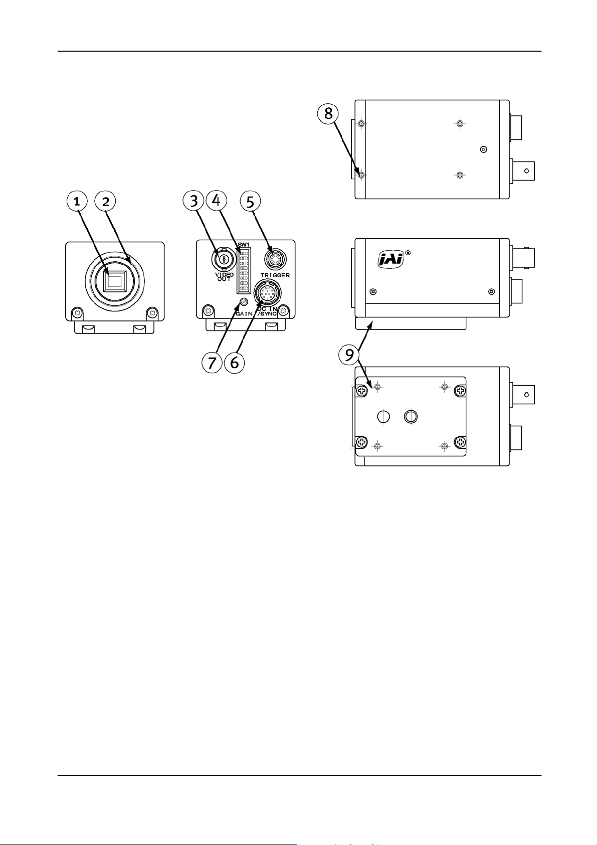
4. Locations and Functions
CV-M30
Fig. 1. Locations
1. 1/2” interline-transfer type CCD sensor
2. Lens mount for C-mount lenses. *1)
3. BNC connector for video output
4. Switch block SW1 for shutter speed and function mode setting
5. 6-Pin connector for Input/output of control signals
6. 12-Pin connector for 12V DC power and external sync signals
7. Gain potentiometer for manual gain adjustment
8. Screw holes for Tripod mount plate. (Screws 3.0 x 5mm)
9. Tripod mount plate to place the camera on a tripod
Note *1): Rear protrusion on the C-mount lens must be less than 10mm (0.4 inches approx.).
When IR-cut filter is used, it must be less than 7.0 mm (0.28 inches approx.).
The IR-cut filter is placed in the C-mount thread.
The C-mount IR-cut filter must be ordered separately.
- 3 -
Page 5
CV-M30
5. Pin Assignment
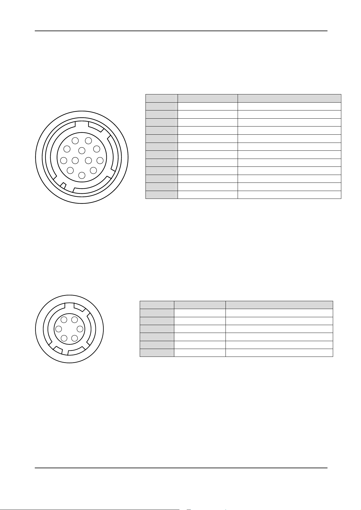
5.1. 12-pin Multi-connector (DC-IN/VIDEO OUT, EXT.HD/VD IN)
Type: HR10A-10R-12PB-01 (Hirose) male
Seen from rear.
Pin no Signal Remarks
1 GND
2 +12 V DC input
3 GND
4 Video output
9
1
2
11
3
4
8
10
7
12
6
5
5 GND
6 HD input
7 VD/trig input
8 GND
9 EEN output
10 GND
11 +12 V DC input
12 GND
Parallel with the BNC connector. *1)
Parallel with pin 5 on 6 pin con. *2)
Parallel with pin 2 on 6 pin con.
Fig. 2. 12 pin connector
Notes:
*1) The video signal on pin 4 is in parallel with the BNC connector.
Avoid double termination
*2) If external trigger pulse is input on either No.7 of 12 pin connector or
No. 5 of 6 pin connector, no external VD signal should be input on the
other.
5.2. 6-pin Multi-connector (TRIGGER)
Type: HR10A-7R-6PB (Hirose) male
Seen from rear.
Pin no. Signal Remarks
1
1
6
2
5
3
4
Fig. 3. 6 pin connector
2
3
4
5
6
RM1
EEN Output
GND
NC
VD/trig input
WEN output
Normal/Double speed. (SW1-5)
Parallel with pin 9 on 12 pin con.
Parallel with pin 7 on 12 pin con. *2)
- 4 -
Page 6
CV-M30
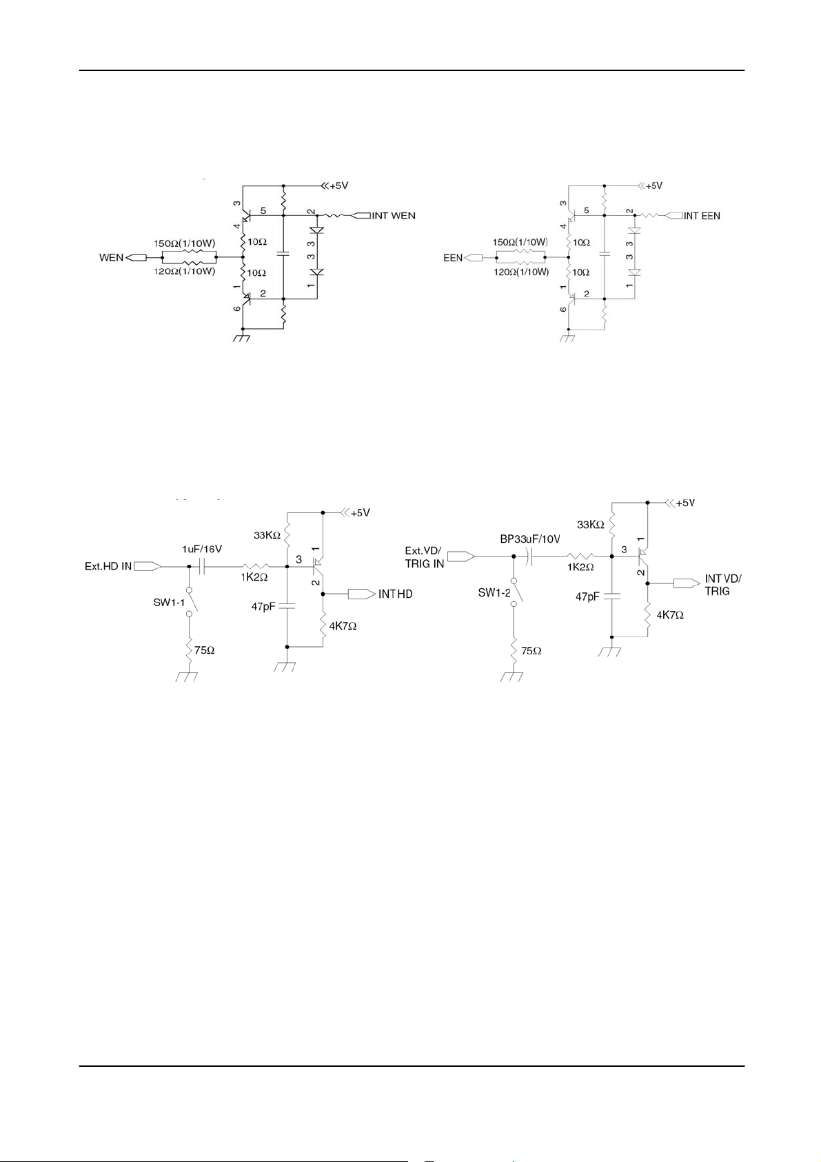
5.3. Input and Output Diagram
Fig. 4. WEN and EEN output
Fig. 5. HD and VD/Trigger input
- 5 -
Page 7

CV-M30
6. Functions and Operations
6.1. Input of External HD/VD Signals
As factory setting the camera can be synchronized by external HD/VD signals. The external
supplied HD/VD signal should follow the same standard as the camera setting for speed, scanning
and interlace. The signal level must be 4.0 Vp-p ±2.0V with 75 Ohm termination on. The
termination can be switched off with the internal switch SW1 on the PK8212 board.
The VD input terminal is used for external trigger signal input in the random trigger modes.
If no external HD is connected, the camera will switch to the internal HD.
If no external VD is connected, the camera will continue with its internal VD.
For settings, see “7. Mode Setting.”
6.2. Continuous Operation
For applications that not require asynchronous trigger, but run in continuous mode, this mode is
used. SW1-7 Trigger is set to Normal (OFF). The camera can operate in normal or double speed.
It is set by with Sw1-5 or at pin 1 on 6 pin connector. The exposure time is selected with SW1-1
to SW1-3. The read out can be 2:1 interlaced, non-interlaced or partial scan. It can be set by
SW1-4 and SW1-6. Partial scanning can only operate in non-interlaced mode. Maximum field rate
with partial scan and double speed is 360 fields per second.
To use this mode
Set: SW1-7 to OFF for normal shutter
SW1-4 to and SW1-6 to interlaced, non interlaced.1/2 partial or 1/3 partial
SW1-1, SW1-2 and SW1-3 to shutter speed.
Input: If external synchronizing is used, input HD and VD.
Ext. VD to pin 5 on 6 pin connector or pin 7 on 12 pin connector..
Ext. HD to pin 6 on12-pin connector.
75 Ohm termination is done with SW1-1 (HD) and SW1-2 (VD) on PK8212 board.
Refer to “6.5.Timing Chart”
For settings, see “7. Mode Setting.”
6.3. External Trigger Mode
This camera has two external trigger modes.
1. Edge Pre-select Mode. (Asynchronous reset and exposure start by an external trigger.)
2. Pulse Width Control Mode. (Asynchronous reset and exposure controlled by the low
period of the external trigger.)
EDGE
PRE-SELECT
Trigger
Exposure
shutter time
Readout
PULSE
WIDTH
Trigger
Exposure
Readout
Fig. 6. External trigger modes
The trigger input is AC coupled, and the exposure will start at the first HD pulse after the trigger
falling edge. The trigger pulse width should be > 1H to < 1000H.
- 6 -
Page 8
CV-M30
6.3.1. Edge Pre-select Mode
The edge pre-select mode will work in non-interlaced and field accumulation mode with partial
scanning and double speed. The CV-M30 starts the exposure (= accumulation of photoelectric
charge) at the first HD pulse after the falling edge of the ext. trigger pulse. The exposure ends
after the time set by the 3 shutter switches SW1-1 to SW1-3. The accumulated signal will be
read out as a single field before a new trigger can be applied. The interval between trigger
pulses must be longer than the time for 1 field + the shutter time. It is the limit for the field
rate. For partial scanning the longest shutter time are not available.
In this mode, the EEN (Exposure ENable) pulse and WEN (Write ENable) pulses are generated and
output from the camera. The EEN pulse indicates the exposure time and can be used to control
the illumination such as strobe light. The WEN pulse indicates the time period of the effective
video signal output, and is useful for the timing and interfacing of external devices such as
frame grabbers.
To use this mode
Set: SW1-7 to ON for ext. trigger shutter
SW1-4 to OFF and SW1-6 to ON for non interlaced mode
SW2-1 on PK8212 board ton OFF for Edge Pre select mode
SW1-1, SW1-2 and SW1-3 to shutter speed
Input: Ext. trigger to pin 5 on 6 pin connector or pin 7 on 12 pin connector.
Ext. HD to pin 6 on12-pin connector. (If used).
75 Ohm termination is done with SW1-1 (HD) and SW1-2 (Trig) on PK8212 board.
Refer to “6.5.Timing Chart”.
Detailed switch setting is described in “7. Mode Setting”.
For connections see “5. Pin Assignment”.
Cautions in the Edge Pre-select Mode.
1. Edge pre-select mode is effective in non-interlaced, field accumulation mode. Double speed
and partial scan can be used.
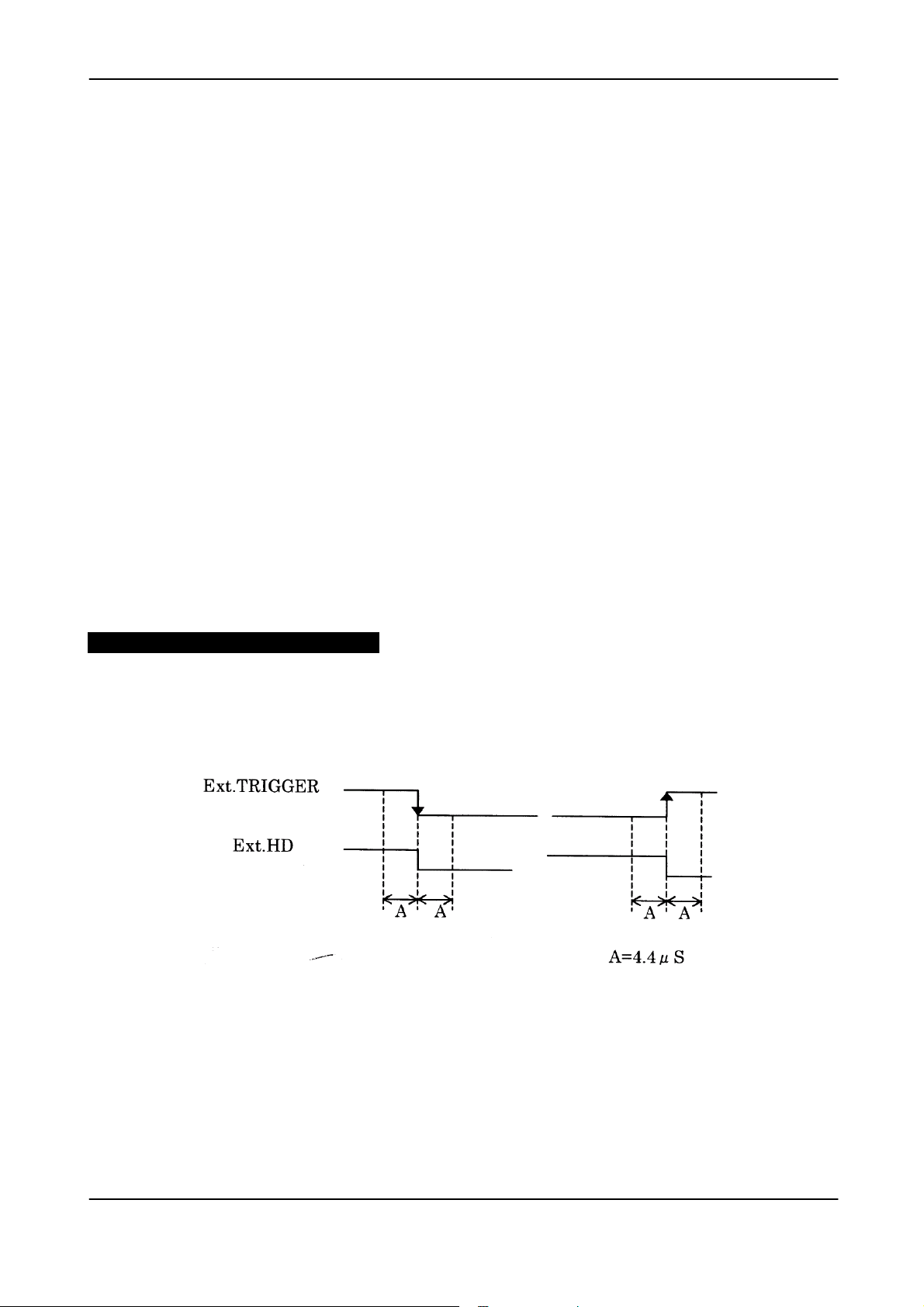
2. The exposure start may delayed up to 1H max., when the falling edge of ext. trigger pulse is
not synchronized with the falling edge of ext. HD signal. To avoid this 1H delay and jitter,
the falling edge of the trigger pulse should be synchronized with the HD pulse as shown
below. It can be the ext. HD input or the Internal HD output.
Fig. 7. External trigger and HD relations
3. The ext. trigger input is 75 Ohm terminated as factory setting. The voltage level of the ext.
trigger has to be 4.0 Vp-p ± 2.0 V. The duration should be more than 1 H negative going. >32
µsec. and < 1000H. The input is AC coupled.
4. If the ext. HD input and ext. trigger input are from a TTL source, set SW1-1 (HD) to OFF and
SW1-2 (ext. trigger) to OFF for non-terminated.
- 7 -
Page 9

CV-M30
6.3.2. Pulse Width Control Mode
The pulse width control mode will only work in non-interlaced field accumulation mode.
The exposure is controlled by the low period of the ext. trigger pulse. The CV-M30 starts the
exposure at the first HD pulse after the falling edge of the ext. trigger pulse. The exposure ends
at the first HD pulse after the rising edge of the ext. trigger. The Shutter can be controlled to be
within the range from >1H (>32 usec.) to <1000H. The AC coupling causes the upper limit.
The accumulated signal will be read out as a single field before a new trigger can be applied.
The interval between trigger pulses must be longer than the time for 1 field + the trigger low
time. It is the limit for the field rate.
In this mode, the EEN (Exposure ENable) pulse and WEN (Write ENable) pulses are generated and
output from the camera. The EEN pulse indicates the exposure time and can be used to control
the illumination such as strobe light. The WEN pulse indicates the time period of the effective
video signal output, and is useful for the timing and interfacing of external devices such as
frame grabbers.
To use this mode
Set: SW1-7 to ON for ext. trigger mode.
SW1-4 to OFF and SW1-6 to ON for non interlaced mode.
SW2-1 on PK8212 board ton ON for Pulse Width Control mode.
Input: Ext. trigger to pin 5 on 6 pin connector or pin 7 on 12 pin connector.
Ext. HD to pin 6 on12-pin connector. (If used).
75 Ohm termination is done with SW1-1 (HD) and SW1-2 (Trig) on PK8212 board.
Refer to “6.5.Timing Chart”.
Detailed switch setting is described in “7. Mode Setting”.
For connections see “5. Pin Assignment”.
Cautions in the Pulse Width Control Mode.
1. Pulse width control mode is effective in non-interlaced, field accumulation mode. Double
speed and partial scan can be used.
2. The exposure start may delayed up to 1H max., when the falling edge of ext. trigger pulse is
not synchronized with the falling edge of ext. HD signal. To avoid this 1H delay and jitter,
the falling edge of the trigger pulse should be synchronized with the HD pulse as shown
below. It can be the ext. HD input or the Internal HD output.
Fig. 8. External trigger and HD relations
3. The ext. trigger input is 75 Ohm terminated as factory setting. The voltage level of the ext.
trigger has to be 4.0 Vp-p ± 2.0 V. The pulse width should be >1H (>32 usec.) to <1000H.
3. If the ext. HD input and ext. trigger input are from a TTL source, set SW1-1 (HD) to OFF and
SW1-2 (ext. trigger) to OFF for non-terminated.
- 8 -
Page 10

CV-M30
6.4. Other Functions
6.4.1. Double Speed Mode
The CV-M30 camera revision D operates only with double speed scanning.
Double speed is 120 fields per second. (V= 119.88Hz. H=31.468 kHz).
To use this mode.
Set:
6.4.2. Partial Scanning Mode
To obtain a higher frame rate, the partial scanning can be used. In this mode only the vertical
center part of the CCD sensor is read out. Partial scan will only work in non-interlaced mode.
The useable image format is
Full non-interlaced 752(h) x 242(v) pixels (120 fields/second in continuous).
1/2 partial 752(h) x 111(v) pixels (240 fields/second in continuous).
1/3 partial 752(h) x 67(v) pixels (360 fields/second in continuous).
With external trigger and partial scan the maximum field rate is less then the above shown. The
maximum field rate is given of the actual shutter time plus the readout time.
To use this mode.
Set: SW1-4 and SW1-6 on the rear panel as follows:
Full SW1-4 OFF, SW1-6 OFF
1/2 partial SW1-4 ON, SW1-6 OFF
1/3 partial SW1-4 ON, SW1-6 ON
Note: In this mode, the shutter speed has limitation depending on the selected range.
Edge pre-select mode.
1/2 partial: Double speed 1/250 to 1/20,000s.
1/3 partial: Double speed 1/500 to 1/20,000s.
6.5. Timing Charts
6.5.1. Video Timing (H)
1clk = 34 ns
Fig. 9. Horizontal timing
- 9 -
Page 11
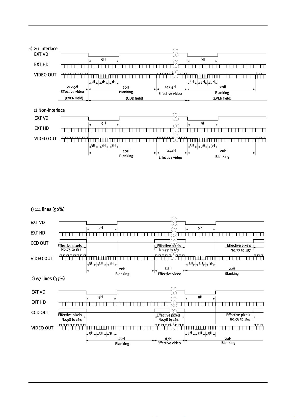
6.5.2. External Sync Mode
CV-M30
H = 31.778 µs
Fig. 10. Vertical timing with external sync
6.5.3. External Sync Mode. Partial Scan
H = 31.778 µs
H = 31.778 µs
Fig. 11. Partial scanning vertical timing with external sync
- 10 -
Page 12

6.5.4. Edge Pre-select
CV-M30
=
Fig. 12. Vertical timing for Edge pre-select
6.5.5. Edge Pre-select. Partial Scan
Fig. 13. Vertical timing for Edge pre-select 1/2 partial scanning
H = 31.778 µs
=
Fig. 14. Vertical timing for Edge pre-select 1/3 partial scanning
- 11 -
Page 13

6.5.6. Pulse Width Control
CV-M30
=
Fig. 15. Vertical timing for pulse width control
6.5.7. Pulse Width. Partial Scan
Fig. 16. Vertical timing for pulse width control 1/2 partial scanning
H = 31.778 µs
H = 31.778 µs
Fig. 17. Vertical timing for pulse width control 1/3 partial scanning
- 12 -
Page 14

7. Mode Setting
7.1. Switch SW1 on Rear Panel
7.1.1. SW1 Lay-out
CV-M30
OFF = <
ON = >
SHUTTER
SCAN mode 1
SCAN mode 2
TRIGGER
GAIN
SW 1
OFF
ON
1
2
3
4
5
6
7
8
Off
1/200
<
<
<
<
<
>
Normal
1/500
1/1000
<
<
>
>
>
<
<
>
<
< < > >
< > < >
< >
< >
1/4000
1/2000
>
>
<
>
>
<
External
AGCMAN
1/20,000
1/10,000
>
>
>
2:1 Interlace
Non-interlace
Part. scan 1/2 N.I.
Part. scan 1/3 N.I.
Fig. 18. Switch settings for switch on rear
7.1.2. Table for SW1 Setting
Switch function
no.
1 Shutter data MSB
2 Shutter data
OFF ON
Refer to shutter table 7.1.3.
Mode setting Switch
For shutter speed select.
3 Shutter data LSB
4 Scan mode 1 Refer to mode table 7.1.4
5 Read out Double speed Normal speed
6 Scan mode 2 Refer to mode table 7.1.4
7 Trigger Normal External
8 Gain Manual gain AGC on
7.1.3. Table for Shutter Time
SW1-1, SW1-2 and SW1-3 is for shutter speed setting.
For 1/2 partial scan thel double speed range is 1/250 to 1/20,000. For 1/3 partial scan the range
is from 1/500 to 1/20,000.
Shutter speed (sec.) SW1-1
MSB
SW1-2 SW1-3
LSB
Double speed
OFF OFF OFF Off (1/120)
OFF OFF ON 1/200 (1/250 with ext. trig.)
OFF ON OFF 1/500
OFF ON ON 1/1000
ON OFF OFF 1/2000
ON OFF ON 1/4000
ON ON OFF 1/10,000
ON ON ON 1/20,000
- 13 -
Page 15

CV-M30
7.1.4. Scan Mode Settings
With SW1-4 and SW1-6 the scanning mode can be selected. The table shows the modes.
SW1-4 SW1-6 Function Mode Remarks
OFF OFF 2:1 Interlaced mode In Normal trigger mode only. (Continuous).
ON OFF 1/2 partial scan Non-interlaced only
OFF ON Non-interlaced
mode
ON ON 1/3 partial scan Non-interlaced only
For detail, please refer to “6.2. Continuous Operation.” and “6.4.2. Partial Scanning Mode.”
7.1.5. Double Speed Mode
Vertical frequency 119.88Hz, and horizontal 31.468kHz.
For detail, please refer to “6.4.1. Double Speed Mode.”
7.1.6. Trigger Mode
With SW1-7 the trigger mode can be changed between normal and external.
Off: for normal mode, which is internal trigger. In this mode the camera run continuously. It can
be interlaced or non-interlaced. (For partial scan only non-interlaced with shutter off.)
On: for external trigger mode, which can be edge pre-select or pulse width control. It is noninterlaced and partial scan with shutter speed select.
For detail, please refer to “6.2. Continuous Operation.” and “6.3. External Trigger Modes.”
7.1.7. Gain Setting Switch
SW1-8 is for the gain select.
Off: is manual gain, which can be adjusted by the potentiometer on the rear panel.
On: is AGC mode. The AGC video level can be adjusted by an internal potentiometer VR1 on
PK8210B board.
Please refer to “8. Internal Adjustments of Video Signal.”
- 14 -
Page 16

CV-M30
7.2. Internal Switch and Jumper Settings
Inside the camera there are switches for 75 termination of external trigger/VD and HD and for
trigger mode select. There are also jumpers for gamma select.
7.2.1. Trigger/VD and HD Termination
On the PK8212 board switch SW1 for 75 Ohm termination of external trigger/VD and HD is found.
SW1-1 is for external HD termination.
SW1-2 is for external trigger or external VD termination.
ON is 75 Ohm termination. It is factory setting.
OFF is for TTL level.
7.2.2. Trigger Mode Select
On the PK8212 board switch SW2-1 for external trigger mode select is found.
SW2-1 OFF for edged pre-select. Factory setting.
SW2.1 ON for pulse width control.
7.2.3. Gamma Select
On the PK8210 board there are 2 jumpers for gamma select. The jumper is mounted as a 1KΩ
resistor.
Gamma JP31 JP36 Remarks
1.0
0.45 NC
7.2.4. Internal Switch Positions
1KΩ
NC Factory setting
1KΩ
Fig. 19. Internal switch positions
7.2.5. Internal Jumper Positions
Fig. 20. Internal jumper positions
- 15 -
Page 17

CV-M30
8. Internal Adjustments of Video Signal
For adjustment of the video output signal there are internal potentiometers on th PK 7987A
board.
Adjustment should only be done in a setup with a standard test chart and controlled illumination
Do not touch these potentiometers unless you are familiar with camera adjustments.
VR 1 is for AGC level setting. Factory setting is 700 mVpp ±30 mV
VR2 is for black level set-up. Factory setting is 20 mVpp ±2 mV
VR3 is for white clip level. Factory setting is 800 mVpp ±30 mV
VR4 is for factory adjustment only. Do not touch!
Fig. 21. Internal adjustments positions
- 16 -
Page 18
CV-M30
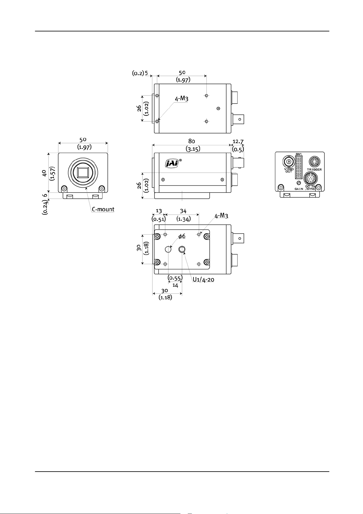
9. External Appearance and Dimensions
Fig. 22. Outline
- 17 -
Page 19

CV-M30
10. Specifications
10.1. Specification table
Model CV-M30
CCD Sensor 1/2”Monochrome IT CCD. Sony ICX-418ALL-6
Image Area 6.45mm (H) x 4.84mm (V)
Effective Pixels 768(H) x 494(V)
Cell Size
Pixels in video output
Double Speed 2:1 interlaced
Non-interlaced
1/2 partial
1/3 partial
Vertical Frequency Double speed 119.88Hz
Horizontal Frequency Double speed 31.468kHz
Pixel Clock Frequency Double speed 28.7MHz
Pixel clocks per line 912
Synchronization Int. X-tal, Ext. VD/HD, random trigger
S/N Ratio >58dB
Sensitivity on sensor 0.1 lx (Max Gain, 50% video)
Ext. trigger mode Continuous, Edge Pre-select, Pulse Width Control
Trigger Input In edge pre-select >1H
Electronic Shutter
Double Speed
Resolution Horizontal 500 TV lines, Vertical 350 TV lines
Gamma 1.0/0.45
Gain
Gain Range
Video Output
Lens Mount C-mount
Environment
Power
Consumption 3W
Dimensions 50x40x80 (WxHxD) mm
Weight 240g
Off (1/120), 1/200, 1/500, 1/1000, 1/2000, 1/4000, 1/10,000, 1/20,000
sec
-5°C to +45°C 20% to 80% (Non-condensed)
Note: Above specifications are subject to change without notice.
10.2. Spectral Sensitivity
8.4 µ m(H) x 9.8 µm(V)
756(h) x 485(v) 60 frames/sec
756(h) x 242(v) 120 field/sec
756(h) x 111(v) 240 fields/sec
756(h) x 67(v) 360 fields/sec
In pulse width >1H to <1000H
Manual/Auto
Composite 1.0 Vp-p, 75Ω
DC+12V ±10%
-3 to + 12dB
1.0
0.8
0.6
0.4
Relative response
0.2
0.0
400 500 600 700 800 900
Wave lenght (nm )
Fig. 23. Spectral sensitivity
- 18 -
1000
Page 20

CV-M30
11. Appendix
11.1. Precautions
Personnel not trained in dealing with similar electronic devices should not service this camera.
The camera contains components sensitive to electrostatic discharge. The handling of these
devices should follow the requirements of electrostatic sensitive components.
Do not attempt to disassemble this camera.
Do not expose this camera to rain or moisture.
Do not face this camera towards the sun, extreme bright light or light reflecting objects.
When this camera is not in use, put the supplied lens cap on the lens mount.
Handle this camera with the maximum care.
Operate this camera only from the type of power source indicated on the camera.
Disconnect the power to the camera before modifications, such as changes of jumper and switch
settings.
11.2. Typical CCD Characteristics
The following effects may be observed on the video monitor screen. They do not indicate any
fault of the CCD camera, but do associate with typical CCD characteristics.
V. Smear
Due to an excessive bright object such as electric lighting, sun or strong reflection, vertical
smear may be visible on the video monitor screen. This phenomenon is related to the
characteristics of the Interline Transfer System employed in the CCD.
V. Aliasing
When the CCD camera captures stripes, straight lines or similar sharp patterns, jagged image on
the monitor may appear.
Blemishes
Some pixel defects can occur, but this does not have en effect on the practical operation.
Patterned Noise
When the CCD camera captures a dark object at high temperature or is used for long time
integration, fixed pattern noise (shown as white dots) may appear on the video monitor screen.
- 19 -
Page 21

CV-M30
12. Users Record
Camera type: CV-M30
Revision: (Revision D)
Serial No. ……………..
For camera revision history, please contact your local JAI distributor.
Users Mode Settings.
Users Modifications.
DECLARATION OF CONFORMITY
AS DEFINED BY THE COUNCIL DIRECTIVE
89/336/EEC
EMC (ELECTROMAGNETIC COMPABILITY)
WE HEREWITH DECLARE THAT THIS PRODUCT
COMPLIES WITH THE FOLOWING PROVISIONS APPLYING TO IT.
EN-50081-1
Company and product names mentioned in this manual are trademarks or registered trademarks of their respective owners.
JAI A-S cannot be held responsible for any technical or typographical errors and reserves the right to make changes to products and
documentation without prior notification.
JAI A-S, Denmark
Phone +45 4457 8888
Fax +45 4491 8880
www.jai.com
JAI Corporation, Japan
Phone +81 45 933 5400
Fax +81 45 931 6142
www.jai-corp.co.jp
JAI UK Ltd, England
Phone +44 0 1895 821 481
Fax +44 0 1895 824 466
www.jai.com
JAI Pulnix Inc, USA
Phone (Toll-Free) +1 877 472-5909
Phone +1 408-747-0300
www.jai.com
EN-50082-1
- 20 -
 Loading...