

Page 1

Digital Monochrome 2 Megapixel
Progressive Scan Camera
CV-M2
Operation Manual
Camera: Revision A
Manual: Version 1.0
M2ManualJul22.doc
JPT 22-07-03
Page 2

CV-M2
Table of Contents
1. General ........................................................................................................2
2. Standard Composition ......................................................................................2
3. Main Features ................................................................................................2
4. Locations and Functions ................................................................................... 3
5. Pin Assignment............................................................................................... 4
5.1. 12-pin Multi-connector (DC-IN/Trigger) ....................................................................... 4
5.2. BNC connector for analogue monitor video output.......................................................... 4
5.3. Digital Output Connector for Camera Link.................................................................... 4
5.4. Input and Output Circuits........................................................................................ 5
5.4.1. Monitor video output ...................................................................................... 5
5.4.2. Iris video output............................................................................................ 5
5.4.3. Trigger input................................................................................................ 5
5.4.4. EEN output .................................................................................................. 5
5.4.5. Camera Link interface .................................................................................... 6
6. Functions and Operations .................................................................................7
6.1. Basic functions .................................................................................................... 7
6.1.1. Dual video output.......................................................................................... 7
6.1.2. Burst trigger ................................................................................................ 7
6.1.3. Restart continuous trigger mode ........................................................................ 8
6.1.4. PIV mode .................................................................................................... 8
6.1.5. Sensor Gate Control ....................................................................................... 9
6.1.6. Digital video out allocation .............................................................................10
6.1.7. Knee function..............................................................................................10
6.2. Sensor layout and timing. ......................................................................................11
6.2.1. CCD sensor layout.........................................................................................11
6.2.2. Vertical timing ............................................................................................11
6.2.3. Horizontal timing single channel .......................................................................12
6.2.4. Horizontal timing details single channel ..............................................................12
6.2.5. Horizontal timing dual channel.........................................................................13
6.2.6. Horizontal timing details dual channel................................................................13
6.2.7. LVAL synchronous accumulation........................................................................14
6.2.8. LVAL a-synchronous accumulation .....................................................................15
6.2.9. Partial scanning vertical timing ........................................................................16
6.3. Input/Output of Timing Signals ................................................................................17
6.3.1. Input of Timing Signals...................................................................................17
6.3.2. Output of Timing Signals.................................................................................17
6.4. Trigger Modes.....................................................................................................17
6.4.1. Continuous Operation (Non triggered) ................................................................18
6.4.2. Edge Pre-select Mode ....................................................................................19
6.4.3. Restart Continuous Trigger mode ......................................................................20
6.4.4. Pulse Width Control Mode ...............................................................................21
6.4.5. Burst Trigger mode .......................................................................................22
6.4.6. PIV mode. ..................................................................................................23
6.4.7. Sensor Gate Control ......................................................................................24
6.5. Other Functions. .................................................................................................25
7. Configuring the Camera.................................................................................. 26
7.1. Mode setting SW1 on rear ......................................................................................26
7.2. RS-232C/Camera Link switch...................................................................................26
7.3. Internal Switch ...................................................................................................26
7.4. RS-232C control ..................................................................................................27
7.5. CV-M2 command list.............................................................................................28
7.6. Camera Control Tool for CV-M2................................................................................29
8. External Appearance and Dimensions ................................................................ 30
9. Specifications .............................................................................................. 30
9.1. Spectral sensitivity ..............................................................................................30
9.2. Specification table...............................................................................................31
10. Appendix .................................................................................................. 32
11. Users Record.............................................................................................. 33
- 1 -
Page 3

CV-M2
1. General
The CV-M2 is a digital 2 megapixel camera designed for automated imaging and ITS (Intelligent
Traffic Systems) applications, featuring high resolution and high speed within a uniform and
compact housing.
The high-speed shutter function, asynchronous random trigger mode and partial scan mode
allows the camera to capture high quality images of fast moving objects with a high frame rate.
Functions like burst trigger, reset continuous trigger mode, analog iris video output, knee and
gamma function for single channel makes the camera suitable for intelligent traffic systems.
The CV-M2 features the Camera Link standardized multiplexed signal output interface.
The latest version of this manual can be downloaded from: www.jai.com
The latest version of Camera Control Tool for CV-M2 can be downloaded from: www.jai.com
For camera revision history, please contact your local JAI distributor.
2. Standard Composition
The standard camera composition consists of the camera main body and tripod mount plate.
3. Main Features
• Digital 1” monochrome 2 megapixel progressive scan CCD camera
• 1600 (h) x 1200 (v) effective 7.4 µm square pixels
• 10 or 8 bit video output as Camera Link
• 17 full frames/second for single channel video readout
• 30 frames/second with dual channel video readout
• One push black level and gain calibrations for dual channel readout
• Higher frame rates with 1/2, 1/4 and 1/8 partial scanning
• Programable partial scanning with 1 line interval for start position and scanned lines
• Edge pre-select and pulse width controlled external trigger modes
• Shutter speed 1/17 (off) to 1/14,000 second in 10 steps
• Programable exposure by edge pre-select shutter 1.5H to 1216.5H with 1 H interval
• Burst trigger for 5 different edge pre-selected exposures in sequence
• Analogue video output for iris control
• Restart continuous trigger mode (RCT) makes it ideal for traffic control (ITS)
• Analog composite video output for CCIR/EIA monitor
• PIV mode (Particle Image Velocimetry) for 2 short exposures with very short interval
• Short ASCII commands for fast mode setup via serial port
• Setup by Windows 98/NT/Win2000 via RS-232C or Camera Link
- 2 -
Page 4
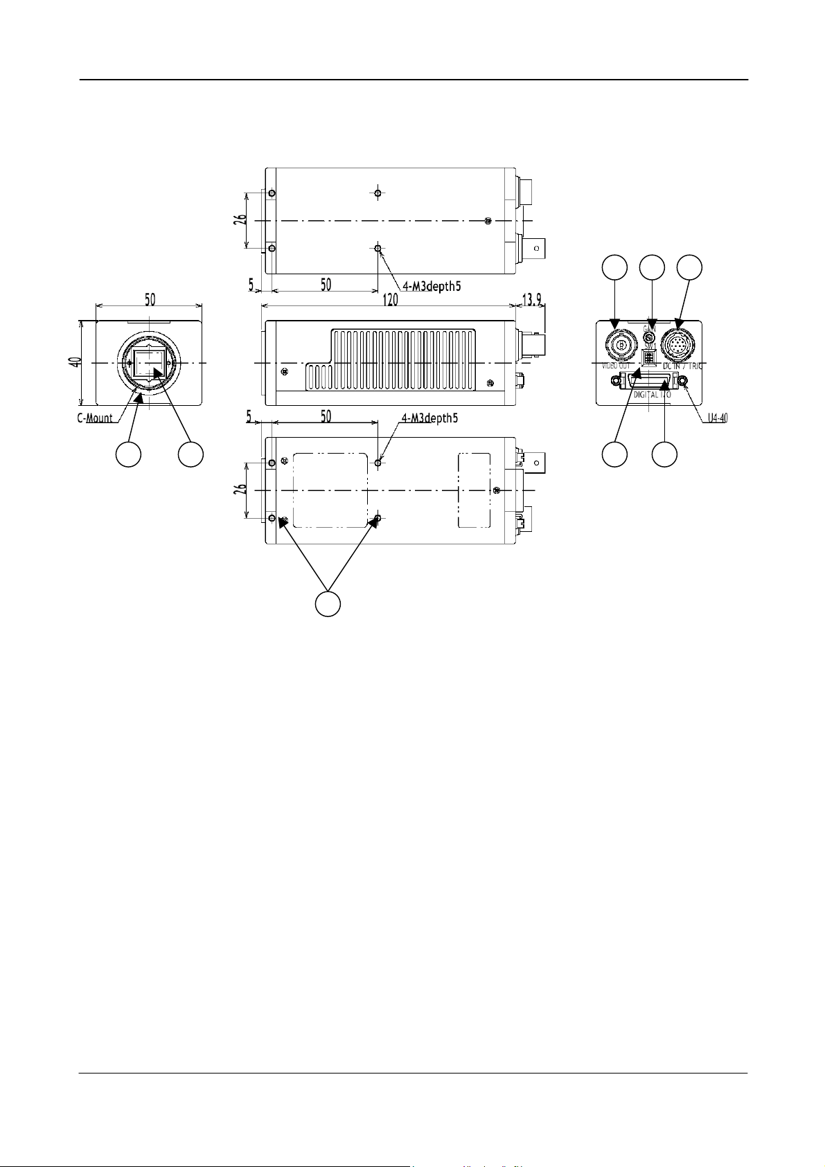
4. Locations and Functions
1. CCD sensor
2. Lens mount (C-mount)
3. Rear panel with SW1
4. Digital output connector (Camera Link)
5. DC in/Trigger in/RS-232C connector
6. BNC connector for monitor video output
7. Gain potentiometer
8. Mounting holes M3. (8x)
CV-M2
7 6 5
3 4 2 1
8
Fig. 1. Locations
- 3 -
Page 5
CV-M2
5. Pin Assignment
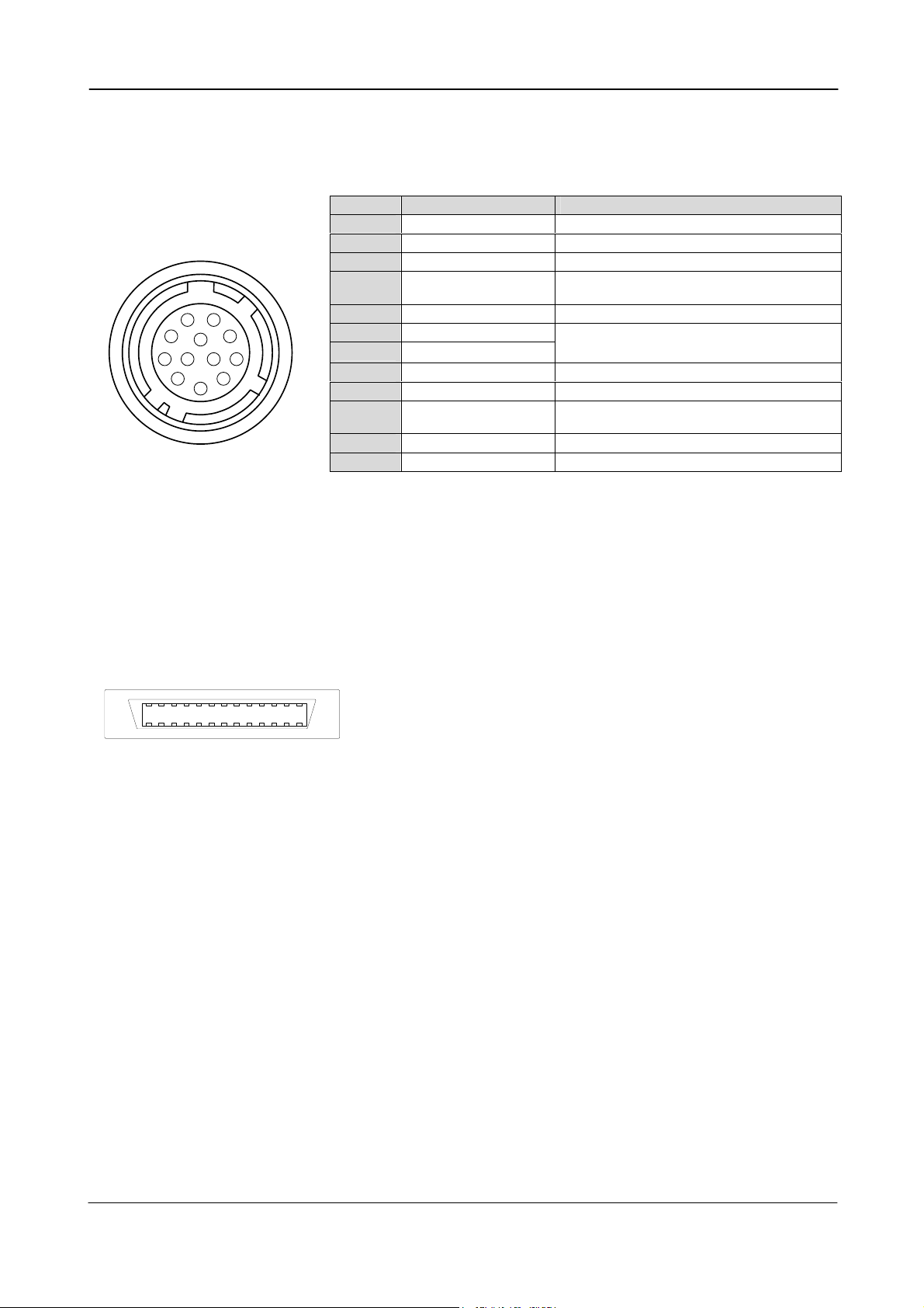
5.1. 12-pin Multi-connector (DC-IN/Trigger)
Type: HR10A-10R-12PB-01
(Hirose) male.
(Seen from rear of camera.)
9
1
2
3
4
8
10
11
7
12
6
5
Fig. 2. 12-pin connector.
Pin no. Signal Remarks
1 GND
2 +12 V DC input
3 GND
4 Iris Video output
5 GND
6 RXD in
7 TXD out
8 GND
9 EEN out
10 Trigger/SG input
11 Factory use
12 GND
*) Refer to 5.4.2. for Iris video output. SG = Sensor Gate Control.
Analogue video for iris control in
continuous mode and RCT mode. *)
RS 232C. Or via Camera Link
By internal switch HR/CL (Refer to 7.2)
Or via Camera Link
TI=1. (Or via Camera Link if TI=0 )
SG=0 trigger input. SG=1 sensor gate contr.
For factory test
5.2. BNC connector for analogue monitor video output
On the BNC connector an analogue video signal (CCIR or EIA) for monitoring is found if OS=2. The
signal can be viewed on a standard monitor as 50 FPS/15.734 kHz 290 lines if MN=1, or 60
FPS/15.734 kHz 240 lines if MN=0. It is non-interlaced and for single channel only. The image
covers the full format, but the resolution is much lower than the digital video output.
5.3. Digital Output Connector for Camera Link
13
26
Fig. 3. Camera Link connector
The digital output signals follow the Camera Link standardized multiplexed signal output
interface. The output driver is NS type DS90CR285, and the receiver is NS type DS90CR286.
The following signals are found on the Digital Output Connector:
SerTC RXD serial data to camera
SerTFG TXD serial data to frame grabber
CC1 Trigger/Sensor Gate input
CC2 Factory use
X0 to X3 Camera Link multiplexed data out
Xclk Camera Link clock. Used as pixel clock.
In the Channel Link X0 to X3 multiplexed signals the following signals are encoded.
D0 – D9 2 x 10 bit video data out for right and left channel.
LVAL Line VALid. Video line data is valid.
FVAL Frame VALid. Video frame data is valid.
DVAL Data VALid. Effective video pixel data is valid
EEN Exposure ENable.
LVAL, FVAL, DVAL polarity is positive. EEN is negative. TRIG is negative as factory setting. TRIG
polarity can be changed by TP. For Camera Link interface principle diagram please check Fig. 7.
1
Type: 26 pin MRD connector
3M 10226-1A10JL
14
(Int. switch HR/CL. Refer to 7.2)
(Int. switch HR/CL. Refer to 7.2)
(TI=0 for CL. SG=1 for Sensor Gate)
(Not specified by Camera Link).
- 4 -
Page 6
CV-M2
5.4. Input and Output Circuits
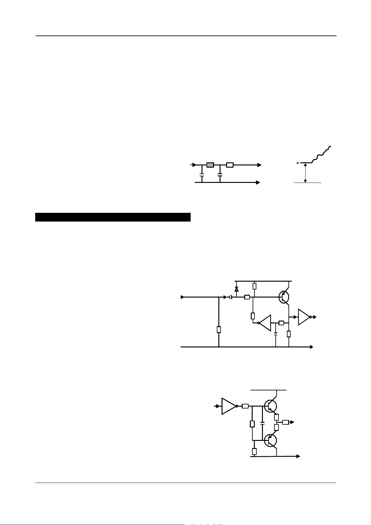
5.4.1. Monitor video output
On the BNC connector an analogue video signal for
set-up is found if OS=2. The signal can be used
for focus and field of view adjust.
CCIR if MN=1. (50 fps, 17.734 kHz, 290 active lines.)
EIA if MN=0. (60 fps, 17.734 kHz, 262 active lines.)
It is for single channel normal (TR=0) operation only.
Shutter speed <313 LVAL (CCIR). <263 LVAL (EIA).
Video is composite 1Vpp from a 75 Ω source.
5.4.2. Iris video output
The analogue video output without composite
sync on pin #4 12 pin Hirose connector is a 75 Ω
DC coupled circuit. It can be used for iris
control if the camera is in normal continuous
mode or Reset Continuous Trigger mode. It is
L
L
1µ2
1µ2
68p
68p
75
75
NC
NC
Video
Video
Output
Output
#4/12
#4/12
GND
GND
Black
Black
level
level
GND
GND
500 mV
500 mV
for single channel only.
Black level is 0.5 volt without termination.
Important note on using this signal for iris control.
The signal for iris video output is taken from the video signal after the gain control. If it is used
for auto iris control, output video level can only be adjusted on the lens level adjust.
Fig. 4. Video output.
5.4.3. Trigger input
+5V
The trigger inputs on pin #10 12 pin Hirose
connector is AC coupled. To allow a long
Trig input pin #10
Trig input pin #10
15k
15k
+5V
pulse width, the input circuit is a flip flop,
which is toggled by the negative or positive
differentiated spikes caused by the falling
100n
100n
1k
1k
68k
68k
100k
100k
TTL
TTL
or rising trigger edges.
10k
GND
GND
10k
1n
1n
1k
1k
GND
GND
The trigger polarity can be changed.
Trigger input level 4 V ±2 V.
The trigger-input impedance is 10 kΩ.
The trigger inputs can be changed to
Camera Link input.
Fig. 5. Trigger input.
+5V
+5V
5.4.4. EEN output
On pin #9 on 12 pin Hirose connector EEN The
output circuit is 75 Ω complementary emitter
followers. It will deliver a full 5 volt signal.
Output level ≥4 V from 75Ω. (No termination).
EEN output is also on Camera Link.
Fig. 6. EEN output
- 5 -
TTL
TTL
100
100
2k2
2k2
10k
10k
75
75
2
2
2
2
#9/12
#9/12
GND
GND
Page 7
CV-M2
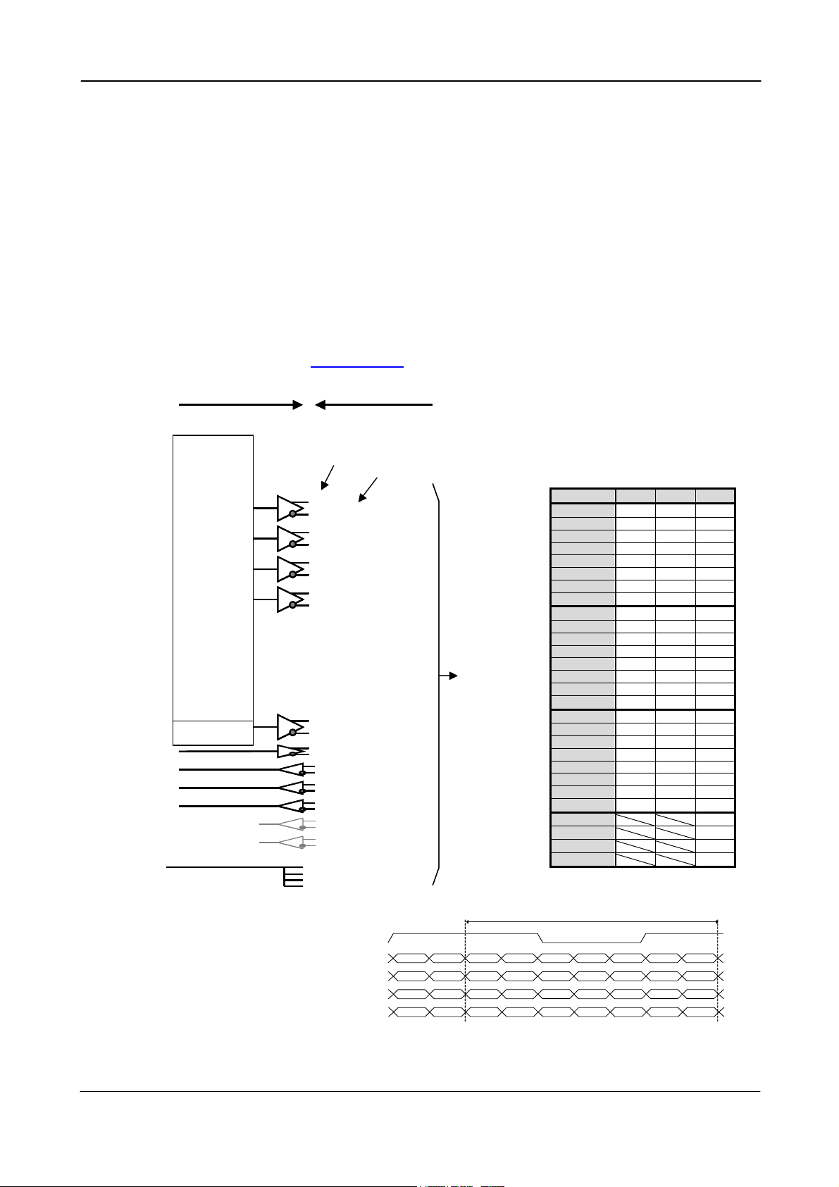
5.4.5. Camera Link interface
The video output is Camera Link, where the 2 channels with 10 or 8 bit video are placed in a
base configuration. The digital output signals follow the Camera Link standardized multiplexed
signal output interface. The output driver is NS type DS90CR285, and the receiver is NS type
DS90CR286.
The data bits from the digital video, FVAL, LVAL, DVAL and EEN are multiplexed into the twisted
pairs, which are a part of the Camera Link. Trigger signals and the serial camera control are
feed directly through its own pairs. The trigger input can also be TTL on the 12 pin connector.
(TI=0 for CL. TI=1 for 12 pin). The serial camera control can be switches between the 12 pin
connector or CL by an internal switch HR/CL. Refer to 7.2
The 26 pin MDR connector pin assignment follows the Camera Link base configuration.
For a detailed description of Camera Link specifications, please refer to the Camera Link
standard specifications found on www.jai.com
Camera Signals
Camera Signals
8bit 10bit
8bit 10bit
L2 L0
L2 L0
L3 L1
L3 L1
L4 L2
L4 L2
L5 L3
L5 L3
L6 L4
L6 L4
L7 L5
L7 L5
L8 L6
L8 L6
L9 L7
L9 L7
R2 L8
R2 L8
R3 L9
R3 L9
R4 NC
R4 NC
R5 NC
R5 NC
R6 R8
R6 R8
R7 R9
R7 R9
R8 NC
R8 NC
R9 NC
R9 NC
NC R0
NC R0
NC R1
NC R1
NC R2
NC R2
NC R3
NC R3
NC R4
NC R4
NC R5
NC R5
NC R6
NC R6
NC R5
NC R5
LVAL
LVAL
FVAL
FVAL
DVAL
DVAL
EEN
EEN
Pclk
Pclk
TXD out
TXD out
RXD in
RXD in
Ext. trig 1 in
Ext. trig 1 in
Ext. Trig 2 in
Ext. Trig 2 in
Ground
Ground
CV-M2 Camera
CV-M2 Camera
Camera Link
Camera Link
Pin
Pin
A 0 Tx0
A 0 Tx0
A1 Tx1
A1 Tx1
A2 Tx2
A2 Tx2
A3 Tx3
A3 Tx3
A4 Tx4
A4 Tx4
A5 Tx6
A5 Tx6
A 6 Tx27
A 6 Tx27
A 7 Tx5
A 7 Tx5
B 0 Tx7
B 0 Tx7
B 1 Tx8
B 1 Tx8
B 2 Tx9
B 2 Tx9
B 3 Tx12
B 3 Tx12
B 4 Tx13
B 4 Tx13
B 5 Tx14
B 5 Tx14
B 6 Tx10
B 6 Tx10
B 7 Tx11
B 7 Tx11
C 0 Tx15
C 0 Tx15
C 1 Tx18
C 1 Tx18
C 2 Tx19
C 2 Tx19
C 3 Tx20
C 3 Tx20
C 4 Tx21
C 4 Tx21
C 5 Tx22
C 5 Tx22
C 6 TX16
C 6 TX16
C 7 Tx17
C 7 Tx17
Txclk
Txclk
Tx24
Tx24
Tx25
Tx25
Tx26
Tx26
Tx23
Tx23
4 x
4 x
7-1
7-1
MUX
MUX
Camera Link Cable
Camera Link Cable
Connector pin
Connector pin
15
15
2
2
X0
X0
16
16
X1
X1
3
3
17
17
X2
X2
4
4
19
19
X3
X3
6
6
18
18
Xclk
Xclk
5
5
21
21
SerTFG
SerTFG
8
8
7
7
SerTC
SerTC
20
20
22
22
CC1
CC1
9
9
10
10
CC2
CC2
23
23
24
24
CC3
CC3
11
11
12
12
CC4
CC4
25
25
1
1
Sheilds
Sheilds
14
14
13
13
26
26
TxCLK
TxOUT3
TxOUT2
TxOUT1
TxOUT0
Fig. 7. Principle diagram for Camera Link base configuration interface
Signal
Signal
Sheilds
Sheilds
Pair 1
Pair 1
Pair 2
Pair 2
Pair 3
Pair 3
Pair 5
Pair 5
Pair 4
Pair 4
Pair 7
Pair 7
Pair 6
Pair 6
Pair 8
Pair 8
Pair 9
Pair 9
Pair 10
Pair 10
Pair 11
Pair 11
A7
C3
B2
A1
- 6 -
To
To
Frame
Frame
Grabber
Grabber
Camera Link bit allocation
C7
EEN
A6
FVAL
DVAL
C2
C0
C1
B1
A5
B0
A0
Time slots in Camera Link
Port/Signal 8bit 10bit Pin No.
Port A0 L2 L0 Tx0
Port A1 L3 L1 Tx1
Port A2 L4 L2 Tx2
Port A3 L5 L3 Tx3
Port A4 L6 L4 Tx4
Port A5 L7 L5 Tx6
Port A6 L8 L6 Tx27
Port A7 L9 L7 Tx5
Port B0 R2 L8 Tx7
Port B1 R3 L9 Tx8
Port B2 R4 NC Tx9
Port B3 R5 NC Tx12
Port B4 R6 R8 Tx13
Port B5 R7 R9 Tx14
Port B6 R8 NC Tx10
Port B7 R9 NC Tx11
Port C0 NC R0 Tx15
Port C1 NC R1 Tx18
Port C2 NC R2 Tx19
Port C3 NC R3 Tx20
Port C4 NC R4 Tx21
Port C5 NC R5 Tx22
Port C6 NC R6 Tx16
Port C7 NC R7 Tx17
LVAL Tx24
FVAL Tx25
DVAL Tx26
EEN Tx23
1 pixel cycl e
C6
LVAL
B5
A4
B6
B7
C4
C5
B3
B4
A2
A3
A6
A7
C2
C3
B1
B2
A0
A1
Page 8
CV-M2
6. Functions and Operations
In the following the format shown in “7.5. CV-M2 command list” are used for function
commands and parameters.
6.1. Basic functions
The M2 camera is a progressive scan camera with 10 or 8 bit video output in single or dual
channel Camera Link. On a BNC connector a standard composite video output CCIR or EIA for
monitor use is found. The image covers the full format, but the resolution is much lower than
the digital video output.
An iris video signal can be used for lens iris control if the camera is in continuous mode or Reset
Continuous Trigger mode.
A knee function (and gamma for single channel) makes it possible to cover high contrast scenes.
The CV-M2 camera has 1/2, 1/4 or 1/8 partial scanning. Programmable partial scan, where the
start line and the number of lines can be selected in 1line increments is also available.
There are 5 trigger modes. Normal continuous, reset continuous trigger, edge pre-select, pulse
width control, edge pre-select burst trigger and PIV trigger. (PIV, Particle Image Velocimety).
The Sensor Gate Control can be used in normal continuous mode together with strobe flash.
The accumulation can be LVAL synchronous or LVAL a-synchronous.
In the following some of the functions are shown in details.
6.1.1. Dual video output
The video read out through Camera Link can be via a single or via double channels. (OS=0 for
single channel, OS=1 for dual channel.) If dual video outputs are used, the frame grabber PC
should reconstruct the image frame from the 2 half images.
Image
Image
The mirrord half
The two half images
The two half images
are stored in separate
are stored in separate
memory locations
memory locations
Camera Link
Camera Link
Interface
Interface
2 x 10 bit
2 x 10 bit
RL
RL
A/D
A/D
A/D
A/D
CV-M2 Camera Frame Grabber
CV-M2 Camera Frame Grabber
R
R
L
L
The mirrord half
image R is reversed
image R is reversed
and stiched together
and stiched together
.
.
with the half image L
with the half image L
Reconstructed
Reconstructed
image on display
image on display
Display
Display
Fig. 8. Dual channel read out
6.1.2. Burst trigger
With the burst trigger function TR=4, five previous set edge pre-selected programmable
exposures can be done with a single trigger pulse. The five shutter times can be set with BSH1
through BSH5. (1H through 1216H.)
Trigger
Trigger
Burst
Burst
Shutter
Shutter
Exposure
Exposure
Video out
Video out
Frame
Frame
1 2345
1 2345
1 234 5
1 234 5
Fig. 9. Burst trigger
- 7 -
Page 9
CV-M2
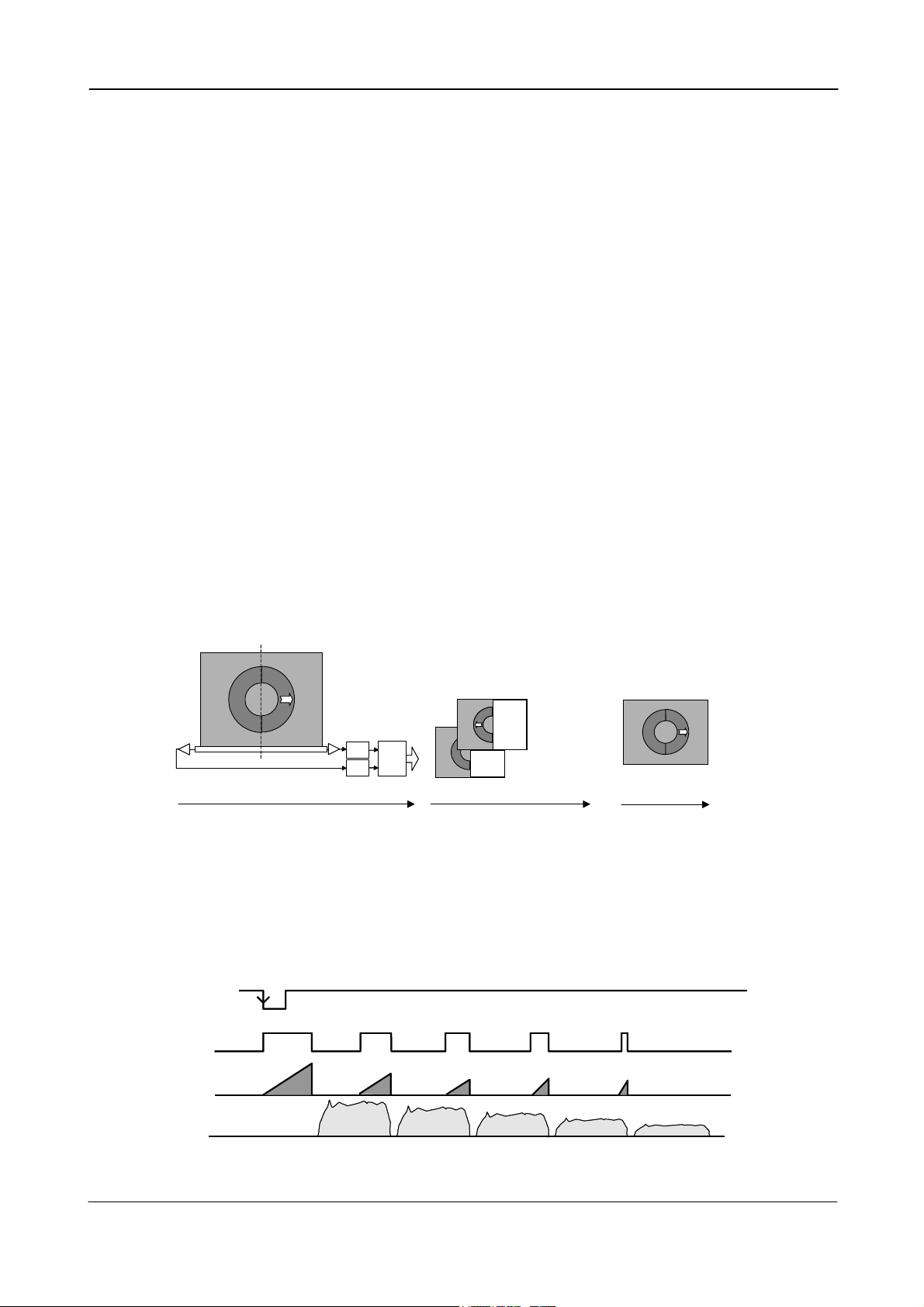
6.1.3. Restart continuous trigger mode
The RCT mode makes it possible to use a lens with video controlled iris for intelligent traffic
surveillance applications. TR=2. The camera is running continuously, and the iris is controlled
from the iris video output. When a trigger pulse is applied, the scanning is reset and restarted,
the previous signal is dumped with a fast dump read out, and the new triggered exposure is
started. This fast dump read out has the same effect as “smearless read out”. Smear over
highlighted areas are reduced for the triggered frame.
Trigger
Trigger
SG
SG
Exposure
Exposure
Dump
Dump
Read out
Read out
Video out
Video out
Continuous video out Continuous video outTriggered
Continuous video out Continuous video outTriggered
Fig. 10. Restart continuous trigger mode
Frame
Frame
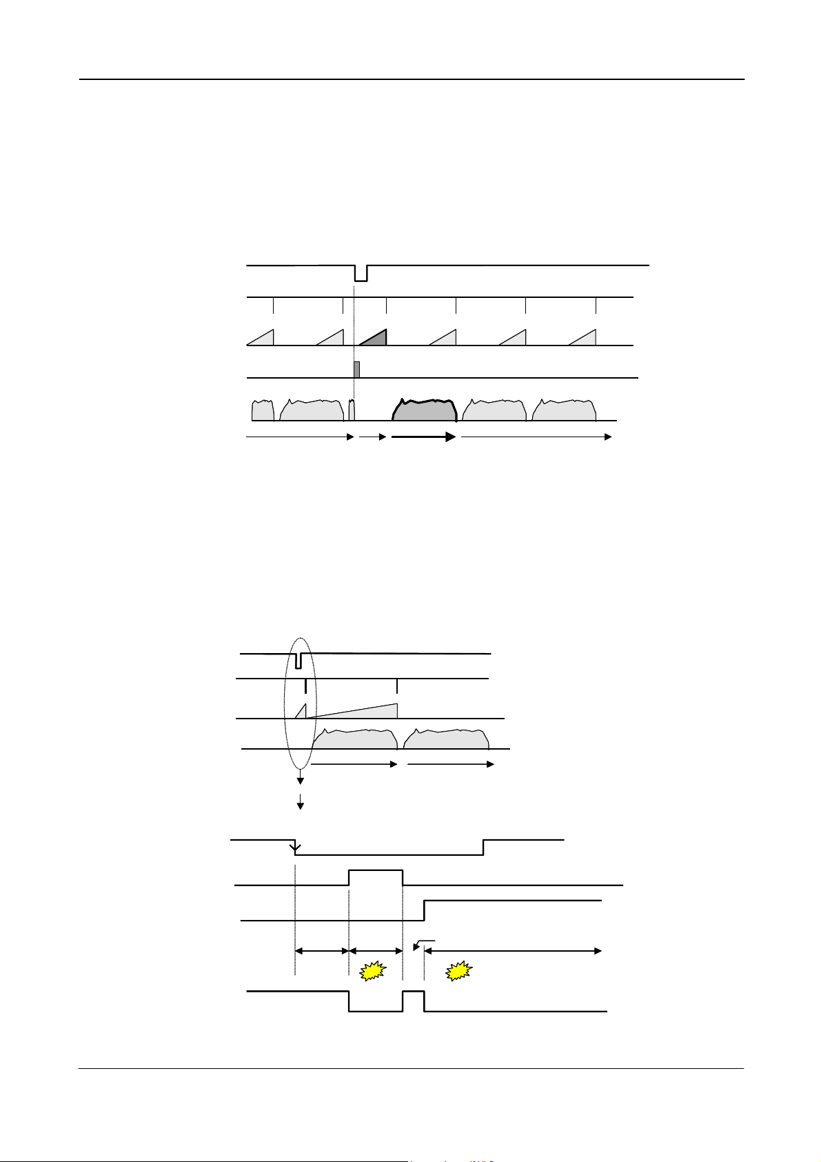
6.1.4. PIV mode
The Particle Image Velocimetry mode can be used in applications where 2 images should be
taken with a very short time interval. TR=5. It can only be used with strobe flash or lasers as
illumination. The first accumulation time is 4 µsec. The second is as long as the time for a full
frame.
Trigger
Trigger
Trigger
SG
SG
SG
Exposure
Exposure
Exposure
Video out
Video out
Video out
Trigger
Trigger
Trigger
Exposure 1
Exposure 1
Exposure 1
Exposure 2
Exposure 2
Exposure 2
Expanded view
Expanded view
Expanded view
First frame out Second frame out
First frame out Second frame out
First frame out Second frame out
1.5µsec.
1.5µsec.
4 µsec.
4 µsec.
4 µsec.
4 µsec.
4 µsec.
4 µsec.
1.5µsec.
EEN
EEN
EEN
1. Flash 2. flash
1. Flash 2. flash
1. Flash 2. flash
Fig. 11. PIV mode
- 8 -
Page 10
CV-M2
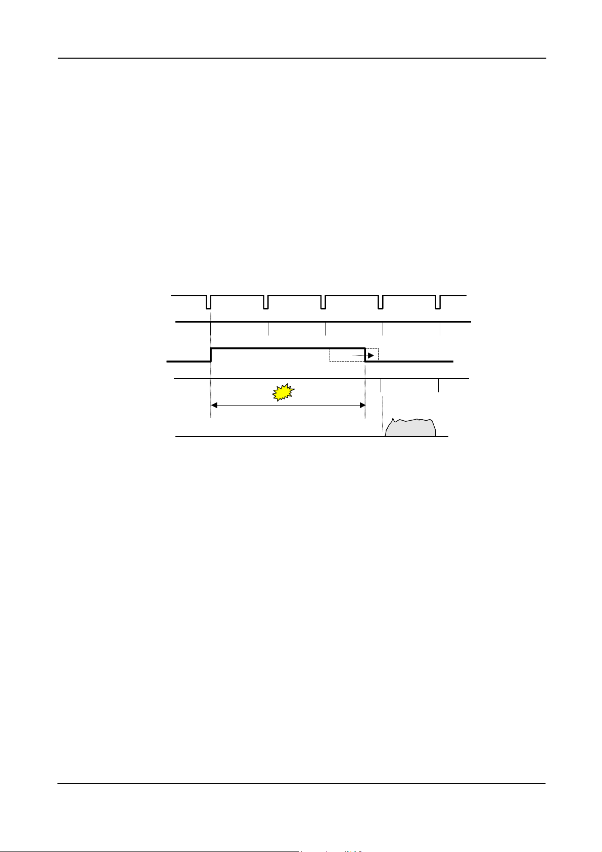
6.1.5. Sensor Gate Control
This function is for applications where a strobe flash is the only illumination, and where the
exact time for the strobe firing is not known. The time window for the strobe firing can be up to
several frames. The resulting video read out can also be delayed by this function. It makes the
synchronization of the frame grabber more flexible.
The Sensor Gate Control signal will inhibit the internal SG signal so the accumulation can
continue. The sensor gate control signal can be synchronized by the FVAL signal.
This function will only work in normal continuous mode. TR=0. The function is on if SG=1.
The SG signal is an internal signal, which is low when the accumulated charge on the photo
diode array is transferred to the vertical ccd registers for read out.
When the Sensor Gate Control input is high, the internal SG pulse is inhibited, and the signal
accumulation on the photo diode array can take place. When the strobe flash is fired, the Sensor
Gate Control signal can be low. The resulting video is then read out after the first FVAL (or SG),
following the falling edge of Sensor Gate Control signal.
FVAL
FVAL
SG
SG
Sensor Gate
Sensor Gate
Control
Control
SG inhibit
SG inhibit
Strobe Flash
Strobe Flash
Video out
Video out
Strobe can be fired here
Strobe can be fired here
Fig. 12. Sensor Gate Control
- 9 -
Page 11
CV-M2
6.1.6. Digital video out allocation
The set-up and the relations between the analog and digital video are shown in fig. 13.
Digital
[LSB]
[LSB]
1023
1023
890
890
Digital
video out
video out
100%
100%
level
level
32
32
Black level
Black level
0
0
0 25 700 800
0 25 700 800
Fig. 13. Digital video bit allocation
White
White
clip level
clip level
Analog
Analog
video out
video out
[mV]
[mV]
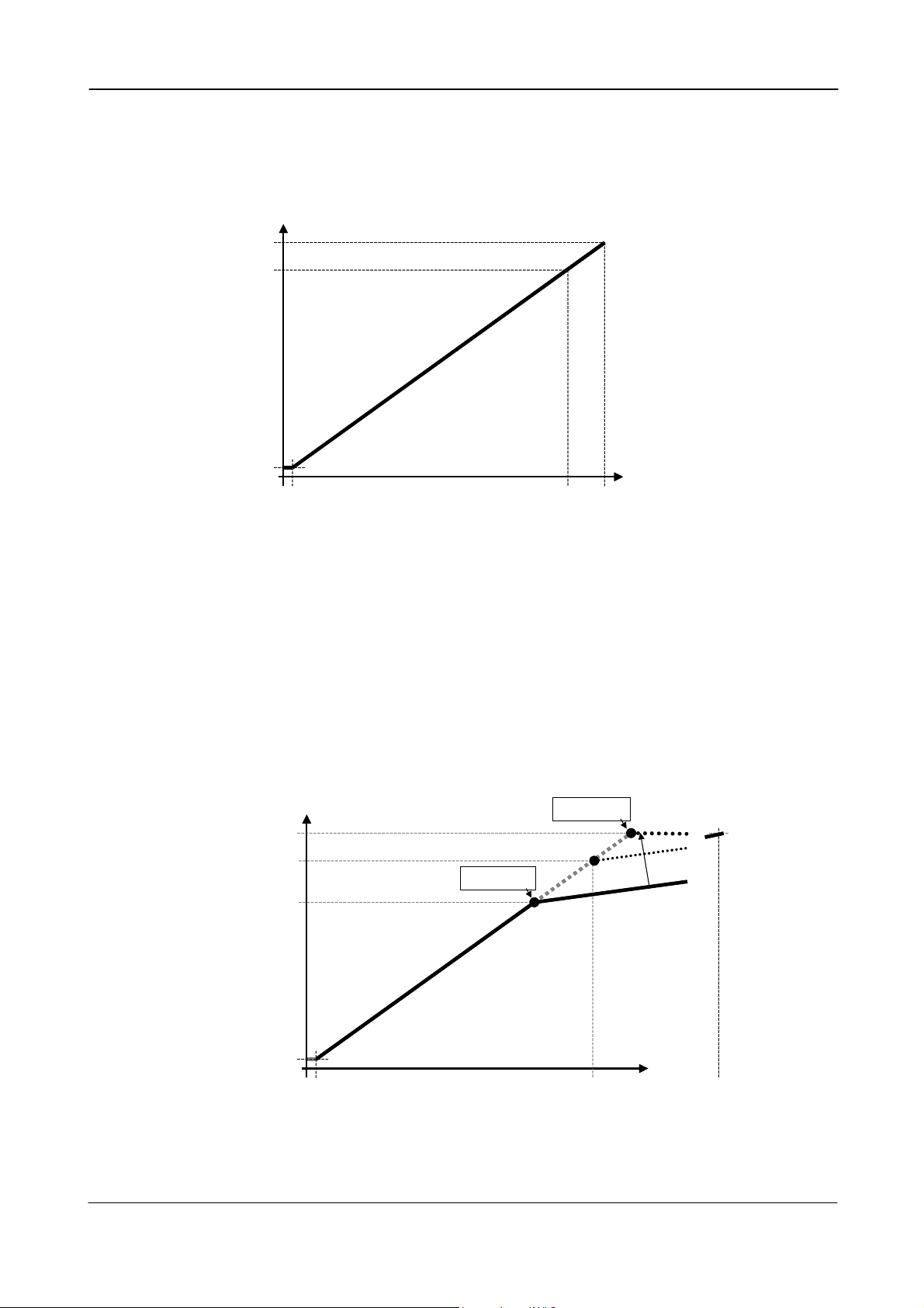
6.1.7. Knee function.
The knee functions can compress the signals in the highlighted areas. The slope over the knee
point is only 20%. The Knee point can be adjusted from 712 to 1023. With the knee at 890, the
camera can reproduce scene highlight up to 175%. The image contrast is reduced to 20% for
scene luminance higher than the knee point.
This function can be used in applications where the scene brightness is divided in an area in
shadow, and another in bright sunshine.
[LSB]
[LSB]
1023
1023
890
890
712
712
32
32
video output
video output
0
0
0
0
Digital
Black level
Black level
Knee min.
Knee min.
lope
lope
S
S
10
10
%
%
0
0
Knee max.
Knee max.
luminance
luminance
100% video
100% video
o
o
l
l
S
S
Scene
Scene
%
%
0
0
2
2
e
e
p
p
175%
175%
Digital
Fig. 14. Knee function
- 10 -
Page 12

CV-M2
6.2. Sensor layout and timing.
6.2.1. CCD sensor layout
The CCD sensor layout with respect to pixels and lines as it is used in the timing and video read
out is shown below.
Bl ank 2 Li nes
2 Optical Black Lines
4 Reser ved Li nes
4244
1
2
3
Ef f e c t i v e Pi x e l s
1600( H) * 1200( V)
4 Reser ved Col umns
16 Opt i c al Bl ac k pi xel s
4 Reser ved Col umns
16 Optical Black pixels
1216
Li nes
1200 Ef f ect i ve Li nes
1198
1199
1200
4 Reser ved Li nes
4 Optical Black Lines
Du mmy & Bl a n k
Si n g l e
Out put
Du mmy & Bl a n k
Dual Lch
Out put
16 16
276
4 4
4
5
2
3
1
1092 Pi x el s
272 272
Vi deo Left 800 Pi xels16 16
4
3
2
1
1916 Pi x el s
Vi deo 1600 Pi x el s
Vi deo Ri ght 800 Pi x el s
9
0
8
0
8
9
9
9
0
9
0
9
7
8
7
7
8
7
7
6
8
9
9
9
5
5
5
1
1
1
1092 Pi x el s
9
0
9
0
5
6
1
1
Du mmy & Bl a n k
4
1
2
3
Dual Rch
Out put
Fig. 15. CCD sensor layout
6.2.2. Vertical timing
Normal mode. Full frame, single and dual channel. 1LVAL = 47.9 µsec (single). 27.3 µsec (dual)
FVAL
LVAL
SUB
SG
Ex po s ur e
Per i o d
EEN
DAT A OUT
DVAL
1 FVAL per i od
1216L
1214L
0. 5L
d
e
v
r
e
s
OB
e
R
2L
4L
1
2345
……
Ef f ect i ve Li nes
1200L
……
6
7
9
8
9
9
9
9
1
1
1
1
1
1
1
1
d
e
v
r
e
s
e
OB
R
4L
4L
0
0
2
1
FVAL
LVAL
2L
k
n
a
l
B
2L
Fig. 16. Vertical timing
- 11 -
Page 13

CV-M2
6.2.3. Horizontal timing single channel
OS=0. Normal mode. Full frame. 1ck = 25 nsec
1 LVAL per i od
1916ck
L VAL
FVAL
SUB
SG
Ex posur e
Pe r i o d
EEN
DAT A OUT
DVAL
CCD Out
1674ck
FVAL Rai s i ng Edge FVAL Fal l i ng Edge
1864ck
444ck
958ck
514ck
mi n: 1. 5L( 1916+958ck)
54ck
OB OB
34ck
6ck
16ck
Re s e r v e d
4ck
Effective Pixels
1600ck
1600ck
1640ck 276ck
Fig. 17. Horizontal timing single channel
Re s e r v e d
4ck
16ck
242ck
190ck
Du mmy+
Bl ank
6ck
276ck
242ck
316ck
52ck
34ck
6.2.4. Horizontal timing details single channel
OS=0. For all modes. Full frame. 1ck = 25 nsec
1 LVAL per i od
1916ck
L VAL
1674ck
FVAL Rai s i ng Edge FVAL Fal l i ng Edge
242ck
FVAL
DAT A OUT
Du mmy+
Bl ank
34ck
54ck
16ck
OBOB
d
e
v
r
e
s
12345
e
R
Ef f e c t i v e Pi x e l s
1600ck
16ck
4ck
7
6
9
9
5
5
5
1
1
1
d
e
9
0
8
v
r
9
0
9
e
5
6
s
e
1
1
R
276ck
Du mmy+
Bl ank
34ck242ck4ck
DVAL
6ck
CCD Out
28ck
OBOB
12345
e
R
d
e
v
r
e
s
Ef f e c t i v e Pi x e l s
7
6
9
9
5
5
5
1
1
1
d
e
9
8
0
v
r
9
9
0
e
5
6
s
e
1
1
R
Fig. 18. Horizontal timing details single channel
- 12 -
Page 14

CV-M2
6.2.5. Horizontal timing dual channel
OS=1. Normal mode. Full frame. 1ck = 25 nsec
1 LVAL per i od
L VAL
FVAL Rai si ng Edge
FVAL
SUB
32ck
514ck
SG
546ck
Ex p o s u r e
Pe r i o d
mi n: 1. 5L( 1092+546ck)
EEN
54ck
34ck
OB
16ck
Re s e r v e d
4ck
DAT A OUT
(L ch)
DAT A OUT
(R ch)
DVAL
6ck
CCD Out
(L ch)
CCD Out
(R ch)
Fig. 19. Horizontal timing dual channel
1092ck
854ck
FVAL Fal l i ng Edge
1040ck
Ef f ect i ve Pi xel s
800ck
800ck
820ck
6ck
238ck
186ck
Du mmy+
Bl a n k
272ck
238ck
272ck
52ck
34ck
292ck
6.2.6. Horizontal timing details dual channel
OS=1. For all modes. Full frame. 1ck = 25 nsec
1 LVAL per i od
L VAL
1092ck
854ck
FVAL Rai si ng Edge FVAL Fal l i ng Edge
238ck
FVAL
DAT A OUT
(L ch)
Du mmy+
Bl ank
34ck
54ck
16ck 272ck
4ck
d
e
v
r
e
s
OB
e
12345
R
Ef f ect i ve Pi xel s
800ck
7
9
6
8
0
9
9
9
9
7
7
7
7
238ck 34ck
0
8
Du mmy+
Bl ank
DAT A OUT
(R ch)
DVAL
6ck
CCD Out
28ck
OB
d
e
v
r
e
s
e
12345
R
Ef f ect i ve Pi xel s
6
9
7
7
6ck
7
8
0
9
9
9
9
0
7
7
8
(L ch)
CCD Out
(R ch)
Fig. 20. Horizontal timing details dual channel
- 13 -
Page 15

CV-M2
6.2.7. LVAL synchronous accumulation
With LS=0, the accumulation will start synchronously with LVAL. The trigger pulse should be
longer than 2 LVAL intervals, and the accumulation will then start at the first LVAL after the
trigger leading edge. The exposure start delay will be up to 1 line. (Single channel 47.9 µsec.
Dual 27.3 µsec).
In EPS mode the exposure stops 0.5 L after the selected shutter time, (in number of LVAL).
In PWC mode the exposure stops 0.5 L after the first LVAL after the trigger trailing edge. It
results in up to 1 LVAL jitter.
In LVAL synchronous accumulation mode a new trigger can start a new exposure during the
previous frame read out, but the exposure may not be finished before the frame is read out. It
makes it possible to have a trigger rate close to the frame rate. (1 FVAL + 3 LVAL).
Important notes on using this mode.
In LVAL synchronous PWC mode exposure jitter up to 1 LVAL can be the result, if the trigger
trailing edge is not synchronized to LVAL.
Min.:2L
Ex t . Tr i g
L VAL
Vi r t u a l SUB
Equi val enc e
Ex p o s u r e
Pe r i o d
DAT A OUT
Ex t . Tr i g
Vi r t ual SUB
Equi val ence
FVAL
Pu l s e
SUB
SG
L VAL
FVAL
Pu l s e
0. 5L
Exposur e del ay:
Max 1L
Sp ec i f i e d Nu mber of LVALs
by shut t er s et
Act ual Exposur e Per i od
Data-out delay
Si ngl e: 1. 5L
Dual : 1. 5L
Fig. 21. LVAL synchronous accumulation in EPS mode
OB
OB
SUB
SG
Ex p o s u r e
Pe r i o d
DAT A OUT
Del ay of expos ur e st ar t :
Max 1L
Act ual Exposur e Per i od
De l ay of ex posur e end :
Max 1L
0. 5L
Data-out delay
Si ngl e: 1. 5L
Du al : 1. 5L
Fig. 21A. LVAL synchronous accumulation in PWC mode
- 14 -
OB OB
Page 16

CV-M2
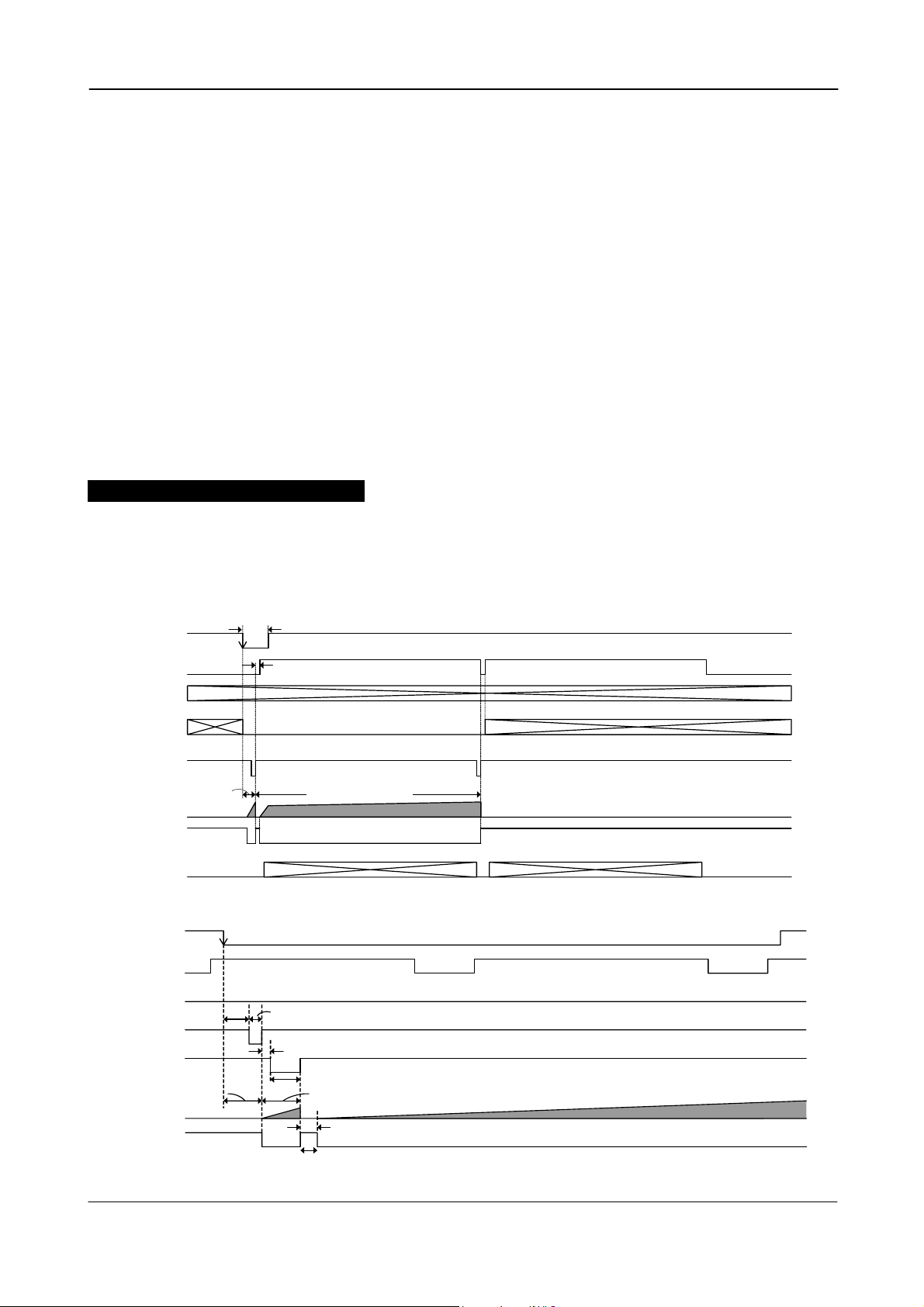
6.2.8. LVAL a-synchronous accumulation
With LS=1, the accumulation will start immediately after the trigger leading edge.
The exposure start delay will be 156 clk. pulses after the trigger. It is 3.9 µsec.
In EPS mode the exposure stops 0.5 L after the selected shutter time, (in number of LVAL).
In PWC mode the exposure stops 0.5 L after the trigger trailing edge.
A new trigger must not be applied before the previous frame is read out. (FVAL is low).
The minimum trigger interval should be longer than the exposure time + 1 FVAL+3 LVAL.
Important notes on using this mode.
In LVAL a-synchronous PWC mode there is no exposure jitter.
Min.:2L
Ext.Trig
L VAL
FVAL
Vi r t u a l SUB
Equi v al ence
Pu l s e
104ck
SUB
SG
Ex posur e
Pe r i o d
DAT A OUT
52ck
Exposur e del ay :
156ck ( 3. 9us)
Speci f i ed Number of LVALs
by shutter set
Act ual Exposur e Per i od
0. 5L
Dat a- out del ay :
0.5L to 1.5L
OB OB
Vi r t u a l SUB
Equi v al enc e
Ext.Trig
L VAL
FVAL
Pu l s e
SUB
SG
Ex posur e
Pe r i o d
DAT A OUT
104ck
Fig. 22. LVAL a-synchronous accumulation in EPS mode
52ck
Exposur e d el ay:
156ck ( 3. 9us)
Act ual Exposur e Per i od
0. 5L
Dat a- out del ay :
0. 5L t o 1. 5L
Fig. 22A. LVAL a-synchronous accumulation in PWC mode
OB OB
- 15 -
Page 17

CV-M2
6.2.9. Partial scanning vertical timing
Partial scanning has 3 pre-selected vertical centred areas 1/2, 1/4 and 1/8. SC=1 through SC=3.
With SC=3, the start and the height of the partial scanned area can be programmed with 1 line
interval. The start line can be programmed with PS=1 through 1151. The scanned height can be
programmed with PC=50 though 1200. Partial scanning will operate with single or dual channel
output. Partial scan is done by a high-speed dump read out of the areas over and under the area
of interest. This partial scanned area is read out with normal speed. The high-speed dump read
out (Front of Frame and in Back of Frame) is done with a speed 18 times faster for single
channel, and 10 times faster for dual channel.
The figures on the timing diagram below are for 1/2 partial scanning.
( * ) Var i abl e Number
2L
FVAL
L VAL
Hi gh Speed
Tr a ns f er
SUB
1 FVAL per i od
670L( * )
668L( * )
Fr o nt o f Fr ame Back of Fr ame
SG
0. 5L
Ex posur e
Pe r i o d
EEN
OB
2L
31L( * )
123
45
Ef f ec t i ve Li nes
600L( * )
31L( * )
9
0
8
6
7
9
0
9
9
9
5
6
5
5
5
OB
4L
Bl ank
2L
DAT A OUT
DVAL
All figures marked with (*) will change with other partial settings. See table below. 1LVAL = 47.9 µsec (single). 27.3 µsec (dual).
Fig. 23. Partial scanning vertical timing
The following table shows the figures for partial scanning.
The maximum frame rate (FPS) for single and dual channel readout is shown for normal mode.
TR=0. For triggered modes it will be lower, because the accumulation time is added to the read
out time. 1LVAL = 47.9 µsec (single). 27.3 µsec (dual).
Table showing values for the vertical timing.
Single channel output Frame Start Frame End
Mode Scanning
SC=0 Full 1 1200 6 0 1200 0 10 17.17
SC=1 1/2 partial 301 900 2 17 600 17 6 32.52
SC=2 1/4 partial 451 750 2 26 300 26 6 57.99
SC=3 1/8 partial 526 675 2 30 150 30 6 95.77
SC=4 Programmable
Start
line
1-1151 50-1200
Stop
line
OB
[LVAL]
2 -
HS
[LVAL]
Effect.
video
[LVAL]
50-1200
Frame
HS
[LVAL]
- 6 -
OB
[LVAL]
rate
[FPS]
Remarks
Full scan
Vertical centred
Vertical centred
Vertical centred
Start & height program.
Dual channel output Frame Start Frame End
Mode Scanning
SC=0 Full 1 1200 6 0 1200 0 10 30.12
SC=1 1/2 partial 301 900 2 31 600 31 6 54.67
SC=2 1/4 partial 451 750 2 46 300 46 6 91.58
SC=3 1/8 partial 526 675 2 53 150 53 6 138.75
SC=4 Programmable
OB = Optical Black. HS = High-Speed dump read out.
Start
line
1-1151 50-1200
Stop
line
OB
[LVAL]
2 -
HS
[LVAL]
Effect.
video
[LVAL]
50-1200
Frame
HS
[LVAL]
- 6 -
OB
[LVAL]
rate
[FPS]
Remarks
Full scan
Vertical centred
Vertical centred
Vertical centred
Start & height program.
- 16 -
Page 18

CV-M2
6.3. Input/Output of Timing Signals
6.3.1. Input of Timing Signals
It is not possible to synchronize the camera from an external sync source except by an extern
trigger pulse. The camera will always run with its internal X-tal controlled timing.
Trigger input through Camera Link. TI=0
Trigger input as TTL on pin #10 on 12 pin Hirose. TI=1
The trigger polarity is active low. TP=0
Trigger input can be changed to active high. TP=1
6.3.2. Output of Timing Signals
To synchronize the video data transfer from the camera the following signals are available in a
base configuration of Camera Link:
FVAL Frame valid High for valid Frame
LVAL Line valid High for valid line
PCLK Pixel clock Rising for data stobe
DVAL Data valid High for valid data
EEN Exposure enable Low during exposure.
See the full connector pin assignment for Camera Link in chapter 5.3 and 5.4.5
For complete documentation on the Camera Link standard, please contact your JAI distributor.
EEN is also found as a TTL signal on pin #9 on the 12 pin Hirose. EEN is low during exposure.
(Not specified by CL).
6.4. Trigger Modes
This camera can operate in 6 primary modes. 1 non-triggered mode and 5 external trigger
modes, which can be set by RS-232C commands.
1. Normal continuous Mode. TR=0 Pre-selected exposure. (SM=0, SM=1)
2. Edge Pre-select Mode. TR=1 Pre-selected exposure. (SM=0, SM=1)
3. Restart Continuous Trigger Mode. TR=2 Pre-selected exposure. (SM=0, SM=1)
4. Pulse Width Control Mode. TR=3 Pulse width controlled exposure.
5. Burst Trigger mode Mode. TR=4 5 EPS. Read out by trailing trig. edge.
6. PIV Mode. TR=5
In normal continuous mode and edge pre-select mode the shutter time can be selected from the
normal 10 fixed steps. (SM=0). Or it can be selected from the 1216 steps programmable (SM=1).
Pulse width control can be used for long time exposure. The trigger pulse width can be from 2
LVAL to ∞. The exposure time is not recommended to exceed 2 seconds.
Partial scan (SC=0 through 3) can be used in all 6 modes.
Important note on changing trigger modes by RS-232C and CL.
Disconnect or stop the trigger input before changing mode by RS-232C or Camera Link. In worst
case it can lead to latch-up of camera function and communication if a mode command is
received at same time as a trigger pulse. The modes are trigger modes (TR) and scanning (SC).
The camera latch-up can only be reset if the power is switched off and on again.
- 17 -
Page 19

CV-M2
6.4.1. Continuous Operation (Non triggered)
Mode settings can be done with RS-232C. Trigger Mode Normal. TR=0. It is for applications where
the camera is continuously running without external trigger. The shutter mode can be normal or
programmable exposure. (SM=0, SM=1). The shutter will work in all 10 steps up to 1/14,000
second or with the programmable exposure in 1216 steps. In partial scanning, shutter times
longer than the actual frame time has no meaning. The exposure will be equal the frame time.
In this mode it is possible to have CCIR/EIA composite analogue video output for monitor use. It
is for full scan only. The video can be 50 or 60 frames per second with a line frequency at 15.734
kHz. CCIR has 290 active lines. Shutter speed <313 LVAL. EIA has 240 active lines. Shutter speed
<263 LVAL.
To use this mode:
Set function: Trigger mode “Normal” TR=0
Shutter mode “Normal” or “Programmable” SM=0, SM=1
“Shutter Speed” SH=0 through 9
“Programmable exposure” PE=1 through 1216
Scanning format SC=0 through SC=4
Output select OS=0, OS=1, OS=2
Polarity and other functions
Important notes on using this mode.
• Analogue video output OS=2 only for full SC=0
For vertical timing refer to 6.2.2. (Fig. 16.)
For horizontal timing refer to 6.2.3 through 6.2.6. (Fig.17. through fig. 20.)
- 18 -
Page 20

CV-M2
6.4.2. Edge Pre-select Mode
In EPS mode, the trigger leading edge will start an exposure at the first LVAL pulse if LS=0, (or
immediately if LS=1), and it stops and the resulting image is read out after the pre-selected
shutter time. It can be the 10 steps in normal or 1216 steps in programmable. SM=0 or SM=1.
This mode will operate with full and partial scanning.
An EEN pulse will indicate the active accumulation time, and a FVAL pulse indicates that the
resulting video is read out.
To use this mode:
Set function: Trigger mode “Edge Pre-select” TR=1
LVAL synchronous accumulation LS=0, LS=1
Shutter mode “Normal” or “Programmable” SM=0, SM=1
“Shutter Speed” SH=0 through 9
“Programmable exposure” PE=1 through 1216
Scanning format SC=0 through SC=4
Output select OS=0, OS=1
Polarity and other functions
Input: Ext. trigger to Camera Link or pin 10 on 12-pin connector.
Important notes on using this mode.
• The duration of the trigger should be >2LVAL to <3FVAL.
• If LS=0 (Synchronous accumulation), the minimum trigger interval is 1 FVAL + 3 LVAL. The
new exposure should not be finish before the previous frame is read out.
• If LS=1 (Asynchronous accumulation) the minimum trigger interval is the exposure time +
3 LVAL. A new trigger must not be applied before FVAL is low.
• 1LVAL = 47.9 µsec (single). 27.3 µsec (dual).
For horizontal timing refer to 6.2.3 through 6.2.6. (Fig.17. through fig. 20.)
For LVAL synchronous accumulation refer to 6.2.7 and 6.2.8. (Fig. 21. fig. 22.)
Ext.Trig1
Ex posur e
DAT A OUT
FVAL
L VAL
SUB
SG
Pe r i o d
EEN
DVAL
1214L
When t he LVAL Sync Accum. : 1.5L
When t he LVAL Async Accum.: 0.5 to 1.5L
d
ve
OB
ser
Re
2L
4L
Ef f ec t i ve Li nes
1
2345
1200L
9
8
6
7
9
9
9
9
1
1
2
1
1
1
1
1
1
1
Fig.24. Edge Pre-select mode vertical timing
- 19 -
d
serve
OB
e
R
4L
4L
0
0
Page 21

CV-M2
6.4.3. Restart Continuous Trigger mode
The RCT mode is in principle the same as normal continuous mode. The difference is that an
external trigger pulse will immediately stop the video read out and reset and restart the vertical
timing. After a fast dump read out, a new triggered exposure is started and read out as normal.
The fast dump read out is performed with a speed 18 times faster for single output, and 10 times
faster for dual output. If no further trigger pulses are applied, the camera will continue in
normal mode. This fast dump read out has the same effect as “smearless read out”. Smear over
highlighted areas are reduced for the triggered frame.
The restart continuous trigger mode makes it possible to use a lens with video controlled iris in
intelligent traffic surveillance applications.
To use this mode:
Set function: Trigger mode “Restart continuous trigger” TR=2
LVAL synchronous accumulation LS=0
Shutter mode “Normal” or “Programmable” SM=0, SM=1
“Shutter Speed” SH=0 through 9
“Programmable exposure” PE=1 through 1216
Scanning format SC=0 through SC=4
Output select OS=0, OS=1
Polarity and other functions
Input: Ext. trigger to Camera Link or pin 10 on 12-pin connector.
Important notes on using this mode.
• The duration of the trigger should be >2LVAL to <3FVAL.
• A new trigger must not be applied before the triggered data is read out.
• 1LVAL = 47.9 µsec (single). 27.3 µsec (dual).
• The time for the fast dump read out (smearless) is 3.3 msec.
For horizontal timing refer to 6.2.3. through 6.2.6. (Fig.17. through fig. 20.)
For LVAL synchronous accumulation refer to 6.2.7. and 6.2.8. (Fig. 21. fig. 22.)
Fast
dump
Fig. 25. Restart Continuous trigger mode
- 20 -
Page 22

CV-M2
6.4.4. Pulse Width Control Mode
In PWC mode, the trigger leading edge will start an exposure at the first LVAL pulse if LS=0 (or
immediately if LS=1). It stops at the trailing edge of the trigger pulse, and the resulting video is
read out. This mode will operate with full and partial scanning. An EEN pulse will indicate the
active accumulation time, and a FVAL pulse indicates that the resulting video is read out.
Long time exposure can be done with pulse width control mode.
To use this mode:
Set function: Trigger mode “Pulse width control” TR=3
LVAL synchronous accumulation LS=0, LS=1
Scanning format SC=0 through SC=4
Output select OS=0, OS=1
Polarity and other functions
Input: Ext. trigger to Camera Link or pin 10 on 12-pin connector.
Important notes on using this mode.
• The duration of the trigger can be >2LVAL to ∞. Thermal noise and dark current noise will
increase by accumulation time, therefore the exposure time is not recommended to
exceed 2 seconds.
• If LS=0 (Synchronous accumulation), the minimum trigger interval is 1 FVAL + 3 LVAL. The
new exposure should not be finished before the previous frame is read out.
• If LS=1 (Asynchronous accumulation) the minimum trigger interval is the exposure time +
3 LVAL. A new trigger must not be applied before FVAL is low.
• 1LVAL = 47.9 µsec (single). 27.3 µsec (dual).
For horizontal timing refer to 6.2.3. through 6.2.6. (Fig.17. through fig. 20.)
For LVAL synchronous accumulation refer to 6.2.7 and 6.2.8. (Fig. 21. fig. 22.)
Ex t . T r i g 1
FVAL
LVAL
SUB
SG
Exposur e
Pe r i o d
EEN
DAT A OUT
DVA L
1214L
t1
t2
When t he LVAL Sync Accum. : t1=0.5 to 1.5L, t2=1.5L
When t he LVAL Async Accum. : t 1=0. 5L, t 2=0. 5 t o 1. 5L
d
e
v
r
OB
2L
Re s e
4L
2345
1
Ef f ec t i ve Li nes
1200L
eser v
R
4L
6
7
8
0
9
9
9
9
0
9
1
1
1
2
1
1
1
1
1
1
Fig. 26. Pulse Width Control mode vertical timing
- 21 -
d
e
OB
4L
Page 23

CV-M2
6.4.5. Burst Trigger mode
With the burst trigger function, a single trigger pulse can start a sequence with five previous set
pre-selected programmable exposures. The five shutter times can be set with BSH1 through
BSH5. (Exposure 1H through 1216H.) The exposure is LVAL synchronous.
The sequence will start with the first exposure at the first LVAL pulse after the trigger leading
edge, and the result is read out after the selected shutter time. During the read out of the
previous frame, the next exposure starts. It will continue until exposure 5 is read out.
This mode will operate with full and partial scanning.
An EEN pulse will indicate the active accumulation time, and a FVAL pulse indicates that the
resulting video sequence is read out.
To use this mode:
Set function: Trigger mode “Burst EPS” TR=4
LVAL synchronous accumulation LS=0
Burst Shutter 1 BSH1=1 through 1216
Burst Shutter 2 BSH2=1 through 1216
Burst Shutter 3 BSH3=1 through 1216
Burst Shutter 4 BSH4=1 through 1216
Burst Shutter 5 BSH5=1 through 1216
Scanning format SC=0 through SC=4
Output select OS=0, OS=1
Polarity and other functions
Input: Ext. trigger to Camera Link or pin 10 on 12-pin connector.
Important notes on using this mode.
• The duration of the trigger should be >2LVAL to <3FVAL.
• A new trigger must not be applied before FVAL is low after frame 5.
• 1LVAL = 47.9 µsec (single). 27.3 µsec (dual).
For horizontal timing refer to 6.2.3 through 6.2.6. (Fig.17. through fig. 20.)
For LVAL synchronous accumulation refer to 6.2.7. (Fig. 21.)
Ext.Trig1
Ex posur e
DAT A OUT
FVAL
L VAL
SUB
SG
Exp. 1 Exp. 2 Exp. 3 Exp. 4 Ex p. 5
Pe r i o d
EEN
Fr a me 1 Fr ame 2 Fr ame 3 Fr ame 4 Fr ame 5
DVAL
Fig. 27. Burst Trigger mode
- 22 -
Page 24
CV-M2
6.4.6. PIV mode.
PIV mode (Particle Image Velocimetry) can be used in applications where 2 images should be
taken with a very short time interval. It can only be used with strobe flash as illumination. The
first accumulation time is fixed at 4 µsec. After a delay >1.5 µsec. the second exposure period
starts. It is as long as the time for a full frame. The accumulation is LVAL a-synchronous. The
first exposure period starts at the trigger leading edge. The first strobe flash should be fired
within the first exposure period, and the second strobe flash during the first frame read out
period. The result will then be 2 frames exposed with the flash interval.
To use this mode:
Set function: Trigger mode “PIV” TR=5
LVAL synchronous accumulation LS=1
Scanning format SC=0 through SC=4
Output select OS=0, OS=1
Polarity and other functions
Input: Ext. trigger to Camera Link or pin 10 on 12-pin connector.
2 strobe flash
Important notes on using this mode.
• The duration of the trigger should be >2LVAL to <3FVAL.
• A new trigger must not be applied before FVAL is low after second frame readout.
• 1LVAL = 47.9 µsec (single). 27.3 µsec (dual).
For horizontal timing refer to 6.2.3. through 6.2.6. (Fig.17. through fig. 20.)
For LVAL a-synchronous accumulation refer to 6.2.8. (fig. 22.)
Ex t . T r i g 1
FVAL
L VAL
Min.:2L
Readout del ay :
1 to 2L
SUB
SG
Fi r st Exposur e Per i od
DAT A OUT
4us( 1/ 250, 000s )
EEN
Ext.Trig
LVAL
FVAL
SUB
SG
Exposur e del ay:
Exposur e
Pe r i o d
EEN
156ck( 3. 9us)
104ck
Second Exposur e Per i od
1 f r ame r ead-out per i od
Fi r s t Fr ame
52ck
40ck( 1us)
120ck( 3us)
Fi r st exposur e t i me:
160ck( 4us)
60ck( 1. 5us)
Fig. 28A. PIV mode details
Se co n d Fr a me
Fig. 28. PIV mode
- 23 -
Page 25

CV-M2
6.4.7. Sensor Gate Control
This function is for applications with strobe flash illuminations or long time accumulations up to
several frames. The resulting video is then read out after the first FVAL (or SG), following the
trailing edge of the Sensor Gate Control signal.
The sensor gate control signal can be synchronized by the FVAL signal. Fig. 29A. and fig. 29B.
shows the minimum sensor gate signal width if it is synchronized to FVAL.
To use this mode:
Set function: Trigger mode “Normal” TR=0
Sensor gate control SG=1
LVAL synchronous accumulation LS=1
Scanning format SC=0 through SC=4
Output select OS=0, OS=1
Polarity and other functions
Input: Sensor gate control to Camera Link or pin 10 on 12-pin connector.
Important notes on using this mode.
Sensor Gat e
Co n t r o l
Si gnal
FVAL
LVAL
SUB
SG
Exposur e
Pe r i o d
EEN
DAT A OUT
al ways Hi gh
al ways Low
Sensor Gat e
Cont r ol Si gnal
Sensor Gat e
Cont r ol Si gnal
SG di sabl e
No Da t a
Fig. 29. Sensor Gate Control
( 1ck=25ns)
FVAL
LVAL
SG
608ck
( 15. 2us)
444ck
1282ck
( 32. 05us)
78ck
(1.95us)
514ck
82ck
(2. 05us)
Fig. 29A. Sensor Gate Control single channel details
( 1ck=25ns)
190ck
(4.75us)
80ck
(2us)
864ck
( 21. 6us)
80ck
(2us)
FVAL
LVAL
32ck
SG
514ck
Fig. 29B. Sensor Gate Control dual channel details
- 24 -
Page 26

CV-M2
6.5. Other Functions.
The following functions are described under their short ASCII command name.
BA: Output bit allocation
With this function the number of bits in the Camera Link video output can be selected to 10 or
8. If 8 bit is selected it is the 8 most significant bits. For the bit allocation in Camera Link
output, please refer to “5.4.5. Camera Link interface” and to fig. 7.
MN: Monitor mode
In normal mode (TR=0) and full frame (SC=0) the output command (OS=2) selects the composite
analogue monitor video system. MN=1 for CCIR (50 FPS, 313 lines, 290 active lines). MN=0 for EIA
(60 FPS, 263 lines, 240 active lines). The line frequency is 15.734 kHz. The video can be seen on
a standard monitor with the command OS=2. SW1.1 can also be used. SW1.1 has highest priority.
TI: Trigger input select
To select the trigger input via Camera Link or pin #10 on Hirose connector as a TTL signal. The
trigger input can also be selected by the internal switch, which has highest priority.
TP: Trigger polarity
This command can change the trigger polarity.
GS: Gamma select
To select gamma 1 or 0.45. 1 is linear relation between scene luminance and video output. 0.45
will expand the contrast in dark and compress the contras in light parts of the scene.
RP: Rear pot
Select master gain from the potentiometer or RS-232C. Sw1.4 has highest priority.
AU: Auto dual adjust
This function is used to calibrate the 2 channels to have same black level and gain.
ABA (Automatic Black Adjust) is a one-push function to align the black level for the 2 channels.
AWA (Automatic White Adjust) is a one-push function to align the white level for the 2 channels.
BL: Black level master
BLF: Black level fine. Right
To adjust the black level for both channels and to fine adjust the R channel.
GA: Gain level master
GLR: gain level fine. Right
To adjust the gain for both channels and to fine adjust the R channel.
KL: Knee point master
KNF: Knee point fine. Right
To adjust the Knee point for both channels and to fine adjust the R channel.
Important notes on using this functions.
Adjusting the gain and black level settings should only be done when the camera is on its
operation temperature. >30 minutes after power on.
- 25 -
Page 27

CV-M2
7. Configuring the Camera
7.1. Mode setting SW1 on rear
Switch SW 1.1 on the camera rear can be used to select digital or analogue video out. SW1.1 has
higher priority than RS-232C.
SW1.2 is for termination of the trigger 1 input on pin #10 Hirose.
(SW1.3 is for termination of the factory test input on pin #11 Hirose)
SW1.4 is for master gain selection. SW1.4 has higher priority than RS-232C.
Fine gain adjustment on R channel by RS-232C.
SW 1
SW 1
1
Video out
Video out
Trig 1 term.
Trig 1 term.
Factory use
Factory use
Gain
Gain
1
2
2
3
3
4
4
Fig. 30. SW1 on camera rear
Digital < > Analog
Digital < > Analog
TTL < > 75Ω
TTL < > 75Ω
TTL < > 75Ω
TTL < > 75Ω
RS-232 < > potm.
RS-232 < > potm.
7.2. RS-232C/Camera Link switch
The internal switch HR/CL can be used to select the control input via the 12 pin Hirose as RS232C or via Camera Link. Factory setting is Camera Link. The switch is placed inside the camera
on the motherboard.
RS- 232C
RS- 232C
NC
NC
1
2
2
Hirose < > Camera Link
Hirose < > Camera Link
< >
< >
1
Fig. 31. Internal Switch
7.3. Internal Switch
The switch is placed inside the camera on the motherboard.
SWSW
Fig. 32. Internal switch
- 26 -
Page 28

CV-M2
7.4. RS-232C control
All configuration of the CV-M2 camera is done via the RS-232C port on the 12 pin HR connector
or via Camera Link. The control mode can be selected by the internal switch RS-232C/Camera
Link. The camera can be set up from a PC running terminal emulator software, or using JAI´s
camera control software.
Below is the description of the ASCII based short command protocol.
Communication setting.
1 CD
Baud Rate 9600 bps
Data Length 8 bit
Start Bit 1 bit
Stop Bit 1 bit
RS 232C cable
CAMERA
CAMERA
Parity None
Xon/Xoff Control None
Protocol.
Transmit setting to camera:
NN=[Parameter]<CR><LF> (NN is any kind of command. Capital or small letters.)
The camera answers:
COMPLETE<CR><LF>
To have all communication visible on the emulator screen, start with:
EB=1<CR><LF>
The camera answers:
COMPLETE<CR><LF>
Transmit request command to camera:
NN?<CR><LF> (NN is any kind of command.)
The camera answers:
NN=[Parameter]<CR><LF>
Transmit the following to have the camera actual setting:
ST?<CR><LF>
The camera answers:
A complete list of the current settings
Transmit the following to have a command list:
HP?<CR><LF>
The camera answers:
A list with all commands and possible settings
Invalid parameters send to camera: (99 is an invalid parameter)
SH=99<CR><LF>
The camera answers:
02 Bad Parameters!!<CR><LF>
To see the firmware number.
VN?<CR><LF>
To se the camera ID. It shows the manufacturing lot.
ID?<CR><LF>
- 27 -
TXD
TXD
RXD
RXD
GND
GND
1 CD
4 DTR
4 DTR
6 DSR
6 DSR
2 RXD
2 RXD
3 TXD
3 TXD
5 GND
5 GND
7 RTS
7 RTS
8 CTS
8 CTS
9 CI
9 CI
9 pin
9 pin
D-con
D-con
PC COM
PC COM
PORT
PORT
Page 29

CV-M2
7.5. CV-M2 command list
Command Name Format Parameter Remarks
A – General settings and useful commands
EB Echo Back
EB=[Param.]<CR><LF>
ST Camera Status request ST?<CR><LF>
HP Online Help request HP?<CR><LF>
VN Firmware version VN?<CR><LF>
ID Camera ID request ID?<CR><LF>
MD Model Name request MD?<CR><LF>
UD User ID
UD=[Param.]<CR><LF>
B – Video Output
OS Output select
BA Output bit allocation
MN Monitor mode
OS=[Param.]<CR><LF>
BA=[Param.]<CR><LF>
MN=[Param.]<CR><LF>
C – Timing and shutter related commands
SC Scanning format
PS Progr. Par. Scan start
PC Progr. Par. Scan hight
TR Trigger mode
SM Shutter mode
SH Shutter speed
PE Programmable expos.
SC=[Param.]<CR><LF>
PS=[Param.]<CR><LF>
PC=[Param.]<CR><LF>
TR=[Param.]<CR><LF>
SM=[Param.]<CR><LF>
SH=[Param.]<CR><LF>
PE=[Param.]<CR><LF>
BSH1 EPS Burst shutter 1
BSH2 EPS Burst shutter 2
BSH3 EPS Burst shutter 3
BSH4 EPS Burst shutter 4
BSH5 EPS Burst shutter 5
BSH1=[Param.]<CR><LF>
BSH2=[Param.]<CR><LF>
BSH3=[Param.]<CR><LF>
BSH4=[Param.]<CR><LF>
BSH5=[Param.]<CR><LF>
D– Signals and polarity
LS LVAL synchronous accum
TI Trigger Input
TP Trigger polarity
SG Sensor Gate control
LS=[Param.]<CR><LF>
TI=[Param.]<CR><LF>
TP=[Param.]<CR><LF>
SG=[Param.]<CR><LF>
E – Gain and analogue signals setting
BL Black level master
BLF Black level R fine
GA Gain level master
GAF Gain level R fine
KN Knee select
KL Knee point master level
KNF Knee point R fine level
GS Gamma select
RP Rear Potentiometer
AU Auto dual adjust
BL=[Param.]<CR><LF>
BLF=[Param.]<CR><LF>
GA=[Param.]<CR><LF>
GAF=[Param.]<CR><LF>
KN=[Param.]<CR><LF>
KL=[Param.]<CR><LF>
KNF=[Param.]<CR><LF>
GS=[Param.]<CR><LF>
RP=[Param.]<CR><LF>
AU=[Param.]<CR><LF>
F – Saving and loading data in EEPROM
LD Load settings from
LD=[Param.]<CR><LF>
camera EEPROM
SA Save settings to camera
SA=[Param.]<CR><LF>
EEPROM
EA EEPROM area request EA?<CR><LF>
*) Disconnect the trigger input before changing mode by RS-232C or Camera Link.
!! Do not try to use commands or parameters not shown in this list.
0=Echo off 1=Echo on Off at power up
Actual setting
Command list
3 letter version
10 Characters
User text ≤16 Characters
0=single chan.
2=monitor
0=10 bit 1=8 bit Camera Link
0=EIA (60FPS) 1=CCIR (50FPS) Analog in BNC
0=full frame
2=1/4 partial
4= progr. p. sc
1-1151 Start line #
50-1200 Hight line#
0=normal
2=Restart Cont
4=Burst EPS
0=Normal 1=Program. exp
0=Off (frame)
2=1/120
4=1/500
6=1/2000
8=1/8000
1-1216 (1.5H to 1216.5H. single chan)
1-1216 (1.5H to 1216.5H. dual channel)
1-1216 (As programmable shutter)
0= syn. accum 1=asyn. accum
0= CamerLink 1= 12 pin Hirose
0= active low 1= active high
0= Off 1= ON Only if TR=0
0-1023 (0=low, 1023=high)
-512 to 511 (-512=low, 511=high)
0-4095 (0 = low, 4095 =high) Range –4 to 14 dB
-2048 to 2047 (-2048=low, 2047=high)
0=Off 1=ON
0-1023 (0=low, 1023=high)
-512 to 511 (-512=low, 511=high)
0=Off ( =1) 1=ON ( =0.45) Single ch. Only
0=manual gain 1=rear potm.
0=Off
2=AWA
0=Factory data 1=User 1 area Latest used data
1=User 1 area
0=Factory data 1=User 1 area Return the latest
1=dual chan. 1-2 Camera Link
1=1/2 partial
3=1/8 partial
1=Edge pre-sel
3=Pulse width
5=PIV
1=1/60
3=1/250
5=1/1000
7=1/4000
9=1/14,000
1=ABA
Parameter = 0 is
≤10 Characters
For user ID data
3 Analog in BNC
*)
*)
All10 steps are
valid in normal
trigger mode, EPS
and RCT mode.
H = 47.9µsec
H = 27.3µsec
at power up
not allowed
used data area
- 28 -
Page 30

CV-M2
7.6. Camera Control Tool for CV-M2
From www.jai.com Camera Control Tool for Windows 98/NT/2000 can be downloaded.
The control tool contents a camera control program and tools for making your own program.
For the integrator and experienced user, the Camera Control Toll is much more than a program
with a window interface. It also provides an easy and efficient ActiveX interface built for MS
Windows 98, ME, NT and 2000. The OCX interface has the ability to connect to the camera using
the serial interface of the PC by reading and writing properties for the camera. This integration
requires simple programming skills within Visual Basic, Visual C++ or similar languages in a
Microsoft Windows environment. Below the different windows are shown.
Fig. 33. Camera Control Tool main bar.
Fig. 34. About window.
Fig.35. Gain setup window.
Fig. 36 Shutter and Sync window.
Fig. 37. Communication window.
- 29 -
Page 31

CV-M2
8. External Appearance and Dimensions
9. Specifications
9.1. Spectral sensitivity
Fig. 38. Outline.
1.0
0.8
0.6
0.4
Relative response
0.2
0.0
300 400 500 600 700 800
Wave lenght (nm )
Fig. 39. Spectral sensitivity for M2.
900
- 30 -
Page 32

CV-M2
9.2. Specification table
Specifications CV-M2
Scanning system Progressive 1216 lines 17 frames/sec.
Pixel clock 40.00 MHz
Line frequency, single output
dual output
Frame rate, single output
dual output
CCD sensor 1” progressive scan monochrome IT CCD
Sensing area 11.8 (h) x 8.9 (v) mm
Cell size
Effective pixels 1600 (h) x 1200 (v)
Pixels in video output
Full
1/2 partial
1/4 partial
1/8 partial
Variable scan
Sensitivity on sensor 1.4 lx (100% video out. Min. gain. 0 dB)
S/N ratio >50 dB
Video output digital single
digital dual
Monitor video output. Analogue
Iris video output. Analogue
Gamma 1.0 or 0.45 (Single channel only)
Knee function Slope 100% to 20%. Knee point adjustable
Gain
Gain range
Synchronization Int. X-tal. Ext. random trigger (LVAL synch. or asynch.)
Inputs TTL
Camera Link
Outputs TTL
Camera Link
Control interface TXD and RXD via RS 232C
Trigger modes
Read out modes Single or dual digital output. Analogue output.
Shutter speed (fixed)
Pulse width control
Programmable exposure
Variable scan 50 to 1200 lines
Functions controlled by
RS 232C
Operating temperature
Humidity 20 – 80% non-condensing
Storage temp/humidity
Power
Lens mount C-mount
Dimensions 40 x 50 x 120 mm (HxWxD)
Weight 310g
1 channel 2 channel
1600 (h) x 1200 (v) 17.17 FPS 30.12 FPS
1600 (h) x 600 (v) 32.52 FPS 54.67 FPS
1600 (h) x 300 (v) 57.99 FPS 91.58 FPS
1600 (h) x 150 (v) 95.77 FPS 138.75 FPS
1600 (h) x 50 (v) to 1200 (v) <167 FPS <208 FPS
Off, 1/60, 1/120, 1/250, 1/500, 1/1000, 1/2000, 1/4000, 1/8000,
20.88 kHz (1916 pixel clock/line). (H = 47.9 µsec)
36.63 kHz (1092 pixel clock/line). (H = 27.3 µsec)
17.17 frames/sec. (1216 lines/frame)
30.12 frames/sec. (1216 lines/frame)
Kodak KAI-2000M
7.4 (h) x 7.4 (v) µm
0.2 lx (50% video out. Max. gain. 12 dB)
10 or 8 bit in Camera Link
2 x 10/8 bit in Camera Link
Composite 1.0 Vpp, 75 Ω (50 or 60 FPS. 15.734 kHz)
0.7 Vpp, 75 Ω (for iris control)
Manual, potentiometer or remote
-3 to +12 dB (0 – 4095)
Ext. trigger TTL 4 V ±2 V
Ext. trigger
EEN output
Pixel clock output
D0-D9 output
DVAL output
LVAL output
FVAL output
EEN output. (Not specified by Camera Link).
TDX and RDX via Camera Link
Continuous, Edge pre-select, Pulse width control,
Reset Continuous Trigger, PIV and
EPS Burst (with 5 programmable shutter times)
Partial scan.
1/14,000 second
1.5 H to ∞. (>72 µsec.) <2 sec. is recommended
1.5 H to 1216.5 H (71.9 µsec. to 58.2 msec.) Single channel
1.5 H to 1216.5 H (41 µsec. to 33.2 msec.) Dual channel
Shutter, Trigger, Scanning, Readout,
Trigger input, Video level, Set-up level and Gain
-5°C to +45°C
-25°C to +60°C/20 – 90% non-condensing
12V DC ± 10%. 6.6 W
- 31 -
Page 33

CV-M2
10. Appendix
Precautions
Personnel not trained in dealing with similar electronic devices should not service this camera.
The camera contains components sensitive to electrostatic discharge. The handling of these
devices should follow the requirements of electrostatic sensitive components.
Do not attempt to disassemble this camera.
Do not expose this camera to rain or moisture.
Do not face this camera towards the sun, extreme bright light or light reflecting objects.
When this camera is not in use, put the supplied lens cap on the lens mount.
Handle this camera with the maximum care.
Operate this camera only from the type of power source indicated on the camera.
Power off the camera during any modification such as changes of jumper and switch setting.
Typical CCD Characteristics
The following effects may be observed on the video monitor screen. They do not indicate any
fault of the CCD camera, but do associate with typical CCD characteristics.
V. Smear
Due to an excessive bright object such as electric lighting, sun or strong reflection, vertical
smear may be visible on the video monitor screen. This phenomenon is related to the
characteristics of the Interline Transfer System employed in the CCD.
V. Aliasing
When the CCD camera captures stripes, straight lines or similar sharp patterns, jagged image on
the monitor may appear.
Blemishes
Some pixel defects can occur, but this does not have en effect on the practical operation.
Patterned Noise
When the CCD camera captures a dark object at high temperature or is used for long time
integration, fixed pattern noise (shown as white dots) may appear on the video monitor screen.
- 32 -
Page 34

11. Users Record
CV-M2
Camera type: CV-M2
Revision: (Revision A)
Serial No. ……………..
Firmware version. ……………..
Camera ID. ……………..
For camera revision history, please contact your local JAI distributor.
Users Mode Settings.
Users Modifications.
DECLARATION OF CONFORMITY
AS DEFINED BY THE COUNCIL DIRECTIVE
89/336/EEC
EMC (ELECTROMAGNETIC COMPABILITY)
WE HEREWITH DECLARE THAT THIS PRODUCT
COMPLIES WITH THE FOLOWING PROVISIONS APPLYING TO IT.
EN-50081-1
Company and product names mentioned in this manual are trademarks or registered trademarks of their respective owners.
JAI A-S cannot be held responsible for any technical or typographical errors and reserves the right to make changes to products and
documentation without prior notification.
JAI A-S, Denmark
Phone +45 4457 8888
Fax +45 4491 8880
www.jai.com
JAI Corporation, Japan
Phone +81 45 933 5400
Fax +81 45 931 6142
www.jai-corp.co.jp
JAI UK Ltd, England
Phone +44 0 1895 821 481
Fax +44 0 1895 824 466
www.jai.com
JAI Pulnix Inc, USA
Phone (Toll-Free) +1 877 472-5909
Phone +1 408-747-0300
www.jai.com
EN-50082-1
- 33 -
Page 35

CV-M2
- 34 -
 Loading...