

Page 1

Progressive Scan
CCD Camera
CV - M10
series
(Rev.B)
Operation Manual
Applicable only for serial no.
CV-M10BX
EIA : E010201
-
CCIR : C010501
-
CV-M10RS
EIA
: E010601
-
CCIR : C010731
-
Page 2
Page 3
.____
.-____
CV-M10
k
ENGLISH
VERSION
DO NOT OPEN
CAUTION:
TO REDUCE THE
SHOCK, DO NOT
BACK), NO USER
INSIDE.
REFER SERVICING
RISK OF ELECTRIC
REMOVE COVER (OR
SERVICEABLE PARTS
TO QUALIFIED SERVICE
I
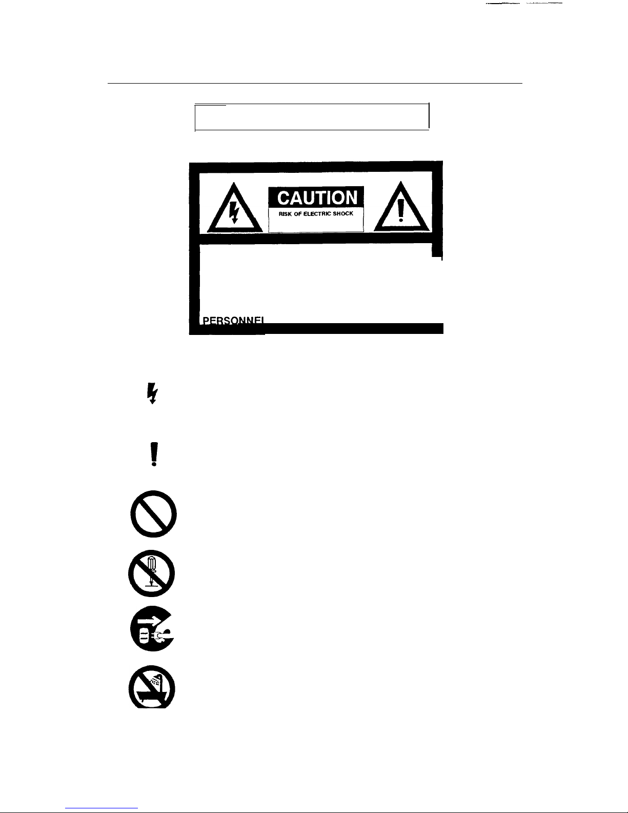
The lighting flash with arrowhead symbol, within an equilateral triangle, is
intend to alert the user to the presence of uninsulated “dangerous voltage”
within the product’s enclosure that may be of sufficient magnitude to
constitute a risk of electric shock to persons.
1
.
The exclamation point
within
an equilateral triangle is intended to alert the
user to the presence of important operating and maintenance (servicing)
instructions in the literature accompanying the appliance.
8
The slash within a circle is intended to alert the user to the presence of
prohibition of any klnd of operation, maintenance and storage.
CD
The abstraction within a circle is intended to alert the user to presence
of prohibition to disassemble the product’s.
The abstraction within a circle is intended to alert the user to power off
the product’s and to take off the plug.
The abstraction within a
of prohibition to expose
of wet place.
circle intended alert the user to presence
the product’s to rain, moisture or any kind
Page 4

CV-M10
Precautions
A@
A@
A
1
AA
Do not attempt to disassemble this camera.
To prevent electric shock, do not remove cover. There
are no user-serviceable parts inside. Refer servicing to
qualified service personnel.
Do not expose this camera to rain or moisture.
Do not face this camera towards the sun, extreme
bright light or light reflecting objects.
Even when this camera is not in use, put the supplied
shade-cap on the camera head.
Handle this camera with the maximum care.
Operate this camera only from the type of power
source indicated on the camera.
Power off the camera during any modification such as
changes of jumper-line and jumper-register.
USER’S RECORD
The production serial number are
shown on the bottom of camera
Model Name
:
Serial No.
:
Page 5

CV-M1
0
Typical CCD Characteristics
The following effects may be observed on the video monitor screen do not
indicate any fault of the CCD camera, but do associate with typical CCD
characteristics.
*
*
*
*
V. Smear
Due to an excessive bright object such as electric lighting, sun or strong
reflection, vertical smear may be visible on the video monitor screen. This
phenomenon is related to the
employed in the CCD.
characteristics
of Interline Transfer System
Vertical Smear
Excessive bright object
Video monitor screen
V. Aliasing
When the CCD camera shoots stripes, straight lines or similar patterns,
jagged image on the monitor may be appeared.
Blemishes
An array of individual sensor elements (pixel) in the CCD image sensor
may consist of blemish, although it is not a problem in practical
operation.
Patterned Noise
When the CCD camera shoots a dark object at high temperature, fixed
pattern noise (dots)
monitor screen.
may be appeared over the entire area of the video
Page 6

CV-M10
Table of Contents
1.
2.
3.
4.
5.
6.
7.
8.
9.
General
........................................................................................................
Main Features
.............................................................................................
Standard Composition
..............................................................................
Locations
....................................................................................................
Pin Assignment
.........................................................................................
Functions
...................................................................................................
Operation and Mode Setting
...................................................................
1)
2)
3)
4)
5)
6)
7)
8)
9)
Shutter “OFF”
........................................................................................
Normal Speed Shutter “ON”
...............................................................
High Speed Shutter “ON”
....................................................................
Long Time Exposure " ON”
................................................................
Random Trigger
...................................................................................
Gain Control.........................................................................................
Interlace System..................................................................................
Gamma Correction
..............................................................................
RS-232C Communication Mode
..........................................................
Ext/Int
HD Operation & Pixel clock output
...........................................
Adjustment of video signal output
level
...............................................
10
. External Appearance
..............................................................................
11
. Specifications
..........................................................................................
1
1
2
3
4
6
12
13
13
14
15
16
18
18
18
18
21
23
24
25
Page 7

I
CV-M10
1.
General
The CV-M10 series (Rev.B) is a newly designed machine vision camera
equipped with a progressive scanning CCD image sensor.
With top
features as progressive scanning and square shaped pixels, the
CV-M10
series offers a superb image quality in versatile applications such as
machine visions, high speed video capturing, pattern recognition, etc.
Model Designation
*
*
CV-M10BXE/RSE
EIA (VGA corresponded) versions are available with
the following features.
-
CV-M10BXE is
the basic progressive scan camera with full
functions.
-
CV-M10RSE
is
the extended version with digital setup function via
RS232C
serial control.
CV-M10BXC/RSC
CCIR
versions are available with the following
features.
-
CV-M10BXC is
the basic progressive scan camera with full
functions.
-
CV-M10RSC is
the extended version with digital setup function via
RS232C
serial control.
2. Main features
*
Progressive Scan CCD sensor of
1/2"
format, interline-transfer type
*
Square Pixel
*
High Speed Shutter
-
CV-M10BXE/RSE:
up to
1/800,000
sec.
-
CV-M10BXC/RSC
: up to l/917,000 sec.
(High speed shutter in
CCIR
verslon is in function only at Random trigger shutter mode.
Without random trigger, it works up to 1/10000 sec.)
- 1 -
Page 8

CV-M10
V
*
*
*
*
*
*
Random Trigger Shutter
-
CV-
M10BXE/RSE
up to 1/800,000 sec.
- CV-M10BXC/RSC up to 1/917,000 sec.
High Resolution
-
CV-M10BXE/RSE
H. 530 and V. 400 TV lines (effective pixel
elements 659H x
494V)
-
CV-M10BXC/RSC H. 550 and V. 400 TV lines (effective pixel
elements 782H x
582V)
VGA Format
The effective elements of CV-M10BXE/BXC correspond to VGA
specifications, besides it produces video signal according to EIA TV
Standards.
Electronics are accommodated in the durable housing of compact
size.
Digital set up via
RS232C
serial control
(CV-M10RSE/RSC
only)
Pixel clock output (User’s option)
3.
Standard Composition
1) Camera main body
x 1
2) 12P Multi connector
x 1
3) 6P Multi connector
x 1
4) Tripod mount plate
x 1
5) Operation manual
x 1
- 2 -
Page 9
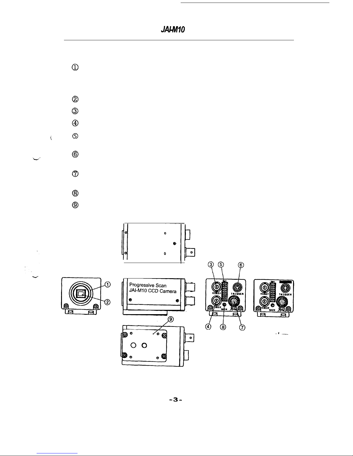
4.
Locations
0
Lens Mount
0
CCD sensor
@
Video output 1
@ Video output 2
@
SW1 switch
@ 6 Pin connector
0
12 Pin connector
@I
GAIN
@I
Tripod mount plate
: C-mount type
Note : Rear protrusion on the C-mount lens must be less
than 7mm (0.28 inch approx.)
:
Interline-transfer type CCD with On-chip lens
:
VS1
.0Vp-p output
:
VS1
.ovp-p output
: Switch on the rear panel to set shutter speed
and other function modes
:
Input of external trigger (WEN output) and
In/Output of communication signals
:
Input of 12VDC power, external sync signals
and output of Video signal
:
Adjusting Gain level of the video output 1
:
Fixing the camera head on tripod or others
CV-M10
BX
CV-M10RS
-3-
Page 10
CV-M10
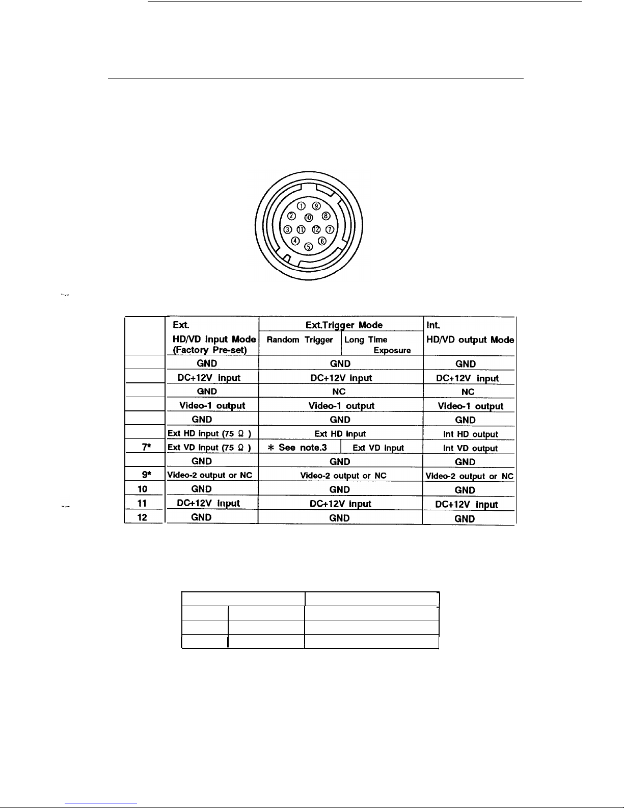
5. Pin Assignment
1)
12P
Multi connector (DC-IN / SYNC)
Pin no
1
2
3
4
5
6*
7*
8
g*
10
k
11
12
HA10A-1
0P-12S
Hirose
*
Note : 1. To change the signal output on pin no.
6,7
and 9, it is necessary to make
jumper setting.
See 8.
Ext/Int HD/VD
Operation and Pixel Clock Output for more information.
Pin No. Factory Pre-set
I
Others
1
6
Ext
HD input
Int HD output
7
Ext VD input
Int VD output
I
9
1
Video-2 output
1
Pixel clock output
2. Video-2 output on pin no. 9 is effective only at
2:1
interlace mode.
3.
Do not input Ext. VD signal at pin no.7 of 12P Multi connector, as it causes a
failure in random trigger mode operation.
- 4 -
Page 11

CV-M10
2) 6P Multi connector (TRIGGER)
HA10A-1 0p-6S Hirose
Pin no.
CV-M10BX
CV-M10RS
1
NC
TXD
2
NC
RXD
3
GND
GND
4
NC
NC
5
Ext. Trigger Input
Ext. Trigger input
6
WEN pulse output
WEN pulse output
Note :
CV-M10
series
camera generates and output WEN (Write
ENable
pulse
at pin no.6 of 6P Multi connector when ext. trigger pulse is input at pin
no.5 of 6P Multi connector.
WEN pulse indicates a duration time of effective video signal
generated by the operation in Random Trigger Mode and Long Time
Exposure Mode, and it is useful to set a timing with frame gabber and
other image processing equipment.
Page 12

CV-M10
6. Functions
1) Progressive Scan
Progressive scanning CCD employed in CV-M10 series was developed
to produce Full Frame Output in shutter mode, enabling to make
the vertical resolution doubled and higher dynamic resolution
compared with the conventional field output images, and thus it
gives
you a great advantage and best solution in the critical image
processing field. The standard scanning camera, being set to shutter
mode produces picture only in the field output gives you a limited
resolution.
2)
Output Signal
in Random Trigger Mode & Long Time Exposure Mode
A.
2:1
Interlace image in field accumulation
2:1
interlaced image in field accum. with two 252.5 lines (EIA), 312.5
lines (CCIR) in
1/60
sec. (EIA),
1/50
sec. (CCIR) are simultaneously
available from Video Output (1) and Video Output (2).
EIA/CCIR
Timing Charts (2:1 Interlace) are described on the following
pages.
-
Video Output (1) is the output in ODD-EVEN-ODD sequence.
- Video Output (2) is the output in EVEN-ODD-EVEN sequence.
These two Interlaced image output in field accumualtion shall be
mixed together in a video capture board, which has to be bought
at a frame grabber supplier.
B. Non-interlace
Non-interlaced image with full 525 lines in
1/30
sec. (EIA) and 625 lines
in
1/25
sec. (CCIR) are available in shutter mode from Video Output (1)
connector.
EIA/CCIR Timing Charts (Non-interlace) are described on
the following pages.
- 6 -
Page 13

CV-M10
A.
2:1
interlace in field accumulation
A-1.
EIA
(HD:63.56
VD:16.7msec.)
(1) Random trigger mode
@ITRIG
!
QHD
IIIIIIIIIIIIIIllIIlllll~~lllll~~~~l~~I
-12ps
min.
Normal shutter
(e.g.
1/1000sec..)
OXSUB I 1 I I
I I I I Ill I
I
I I I I I I II
@XSG
.
1/1000sec.
4
OWEN
i-l
4 lines each are optical black
High speed shutter (e.g.
1/40000sec.)
@XSUB
I I I I
I
I II I I I I I I I I I I I I III l l 11 l I I II l 11
I
r
OX=
,L
~/mooosec.
@HEN
l-l
1
@VIDEOI
I I I
I; 1
I I I I I I
m
Y Y Y Y
Y-y Y Y Y Y VIWI Y V Y r
@VIDEOZrIII llllll-fl!!YF
. ‘i-10
c
4 lines each are optical black
(2) Long-time Exposure mode
(e.g.
2FLD)
Thls mode does not work at Random Trigger mode.
@VD
u
LJ
L
@WEN
I
@viDE0i
U
II-
@VIDEO2
u
Is
.
c
- 7 -
Page 14

CV-M10
A-2.
CCIR (HD:64.0b
sec. VD:20msec.)
(1) Random trigger mode
QRl3lG
0
@HD
1111 l1llllllllllllllllllllllllllllllll
-
2ys
min.
Normal shutter
(e.g.
1/100Osec.)
,@XSUB 1
, ,
,;
I I I I I II I
I I I I I I II I
@XSG
OWEN
i-l
4 lines each are optical black
High speed shutter
(e.g.
1/50000sec.)
High speed shutter
(~/Z~OOO-1/917ooOsec.) works only
at
Random Trigger mode.
@XSUB
I I I II I
I
I I I Ill I I I I I I I I I II I I I II I I II II I I
@XSG
+J&_
1/5oooosec.
@WEN
1
@viDE0111
I I
~I~//~Yhttps://manualmachine.com/YY_~~CYYY/F
@VIDEO2
I
I
I I
2460
I
I I I I I
. 7HD
mmyyyyyyyym
4 lines each are optical black
(2) Long-time Exposure mode
(e.g.
P-FLD)
This
mode does not work at Random Trigger mode.
@VD
l-l
l-l
@WEN
I
I
@VIDEOI
u
I?
@VIDEO2
u
u
II
u
I
FLD
.
-8-
Page 15

CV-M10
B. Non-interlace
B-l. EIA (HD:63.5 sec. VD:33.4msec.)
(1) Random trigger mode
@TRIG -
1)
@HD
IIIIIIIlIIflllllllllllllllllllllllllll
-2~s
min.
”
Normal shutter
(e.g.
VlOOOsec.)
@XSUS
1 I
,,I
I I I I I I I
I I I I I I I I II
@XSG
OWEN
1
@VIDEOS 1m71-m-r-m
I I I I
arc
14 HD
*
.
8
lines are optical black
High speed shutter
(e.g.
1/4OOOOsec.)
@XSG
A-
1/4oooosec.
@HEN
1
@VIDEOS
I
I
I I I I I I I 17 I I
I 11-7
14HD
*
c
8 lines are optical black
(2) Long-time Exposure mode
(e.g.
4-FLD)
This mode does not work at Random Trigger mode.
@ND
LJ
J
-I
Ll
L
-2
FLD=1/3Q
@WEN
I
I
I
1
@v1~E01
II
Ll
u
.
4FLD
.
- 9 -
Page 16

CV-M10
B-2.
CCIR (HDM.Opsec. VD:40msec.)
(1) Random trigger mode
@TRIG
II
@HD
111111111111111111111111ll~~~IllIlllll
-2~s
min.
Normal shutter
(e.g.
l/lOOOsec.)
“@XSUB I I I 11
III
III l II l l II 11 l I
@XSG
OWEN
1
@vIDEo~~~~~
11111111~~~~~~~~
IIIIII~T~~ITWFI
123
14 HD
.
c
8 lines are optical black
High speed shutter
(e.g.
1/5OOOOsec.)
Hlgh speed
shutter
(l/2SOOO-l~lX)0Osec.)
works only at Random Trigger mode.
@IXSUB I I I 1 1 I I I I I
I
I I I I
I I I I III I I I I I I I I I I I I I I I
@XSG
A-
1/5oooosec.
@WEN
1
@vIDEol
I I I
.I
I I I I I I I I I I
WI-I-~/~!~~~~‘~‘!‘~
1 1
m
14HD
.
.
8 lines are optical black
(2) Long-time Exposure mode
(e.s
4-FLD)
This mode does not work at Random Trigger mode.
@!ND
u
-I
-I
u
u
l
2 FLD=l/2%
@WEN
I
I
I
@VIDEOI
U’
IJ
u
U7
l
4FLD
l
-
10
-
Page 17

3)
VGA Format
The pixel of CV-M10
series
(EIA : 659H x
494C, CCIR
:
782H x 582V )
offers capability to meet the VGA format which is internationally
utilized for computer display applications having
640H x 480V
numbers of pixels, besides it produces standard video signals
according to EIA.
4)
5)
6)
7)
Analog Output
CV-M10
series produces analog output only. There is no A/D converter
at output stage, nor video memory
in the camera main body.
Scan Speed
CV-M10
series camera makes scanning with the frequencies according
to the conventional TV Standards.
H. frequency 15.734KHz and V. frequency 60Hz
(CV-M10BXE/RSE)
H. frequency 15.625KHz and V. frequency 50Hz
(CV-M10BXC/RSC)
Random Trigger Shutter (asynchronous)
CV-M10
series is equipped with the asynchronous random trigger
shutter up to l/800,000 sec. for
CV-M10BXE/RSE,
and up to l/917,000
sec. for CV-M10BXC/RSC.
RS-232C Serial Control (available on CV-M10RSE/RSC only)
Camera set-up functions such as GAMMA, GAIN, WHITE CLIP,
SET-UP LEVEL, SCAN MODE, TRIGGER MODE, SHUTTER- SPEED,
RANDOM TRIGGER through RS-232C Digital Serial Control are
provided
as standard on the
CV-M10RSE/RSC
model.
-
11
-
Page 18

CV-M10
7.
Operation and Mode Setting
SW1 switch on PK8080 located inside the camera and SW1 DIP switch
on the rear panel are provided for mode settings such as shutter
function, Random trigger, Gain, Gamma and Interlace and Non-Interlace
scanning.
A. SW1 DIP switch on the rear panel (Factory setting
:
Normal Shutter Mode)
#1
Shutter speed D2
#2
Shutter speed
D1
#3
Shutter speed DO
OFF
ON
#4 Random trigger shutter (ON: Normal mode)
#5
Interlace system(ON:Non-interlace/OFF: Interlace)
#6 Gamma (OFF: 1.0)
#7 AGC
#8 Gain
Note : See table on page 16.
:
#5
ON : Non-interlace output Video 1 only, OFF : Interlace output Video 1 & 2
B. SW1 s on
PK8080
board inside camera available only on
CV-M1
0BXE/BXC
-ON
-
(Factory setting : Normal Shutter Mode)
#l
Shutter mode :
MD0
(OFF : up to
1/10000
sec.
ON
:
up to
1/20000
sec. for EIA
1/25000
sec. for CCIR)
#3 Shutter mode : MD1
mode
:
MD2
-OFF-
#l #2
#3 #4
*
Note : SW1 switch on PK8080 located inside the camera is provided
only for shutter modes of “Shutter OFF”, “Normal Speed”,
“High Speed” and “Long Time Exposure”. Do not touch this
SW1 for the other purposes other than the settings of these
shutter modes.
-
12
-
Page 19

CV-M10
1)
Shutter “OFF”
Use SW1 switch on PK8080 board located inside camera.
Mode
Pos.
#1
Shutter off OFF
Pos.
##2
OFF
Pos.
#3
OFF
Pos.
#4
OFF
Note 1
:
Note 2 :
In this “Shutter OFF” condition, the camera can not accept
External Trigger.
When you use External Trigger, refer to the
following item 2) for Normal Speed Shutter “ON”, and
set this SW1 to the original factory setting (Pos.
#l, #2,
#4 to
OFF, and
##3
to ON).
“Shutter OFF” condition can also be set by SW1 DIP switch
on the rear panel. Refer to the following item 2) for Normal
Speed Shutter "ON"and set Pos.
#l, I%?, #3
of SW1 DIP
switch on the rear panel to OFF positions to make shutter
speed
1/60
(EIA) or
1/50
(CCIR) which gives the same
condition as “Shutter OFF”.
Shutter speed at “Shutter OFF”
Interlace [sec.] Non-Interlace [sec.]
EIA
1/60
1/30
CCIR
1/50
1/25
#Random trigger does-not work at this mode.
2) Normal Speed Shutter “ON”
Use SW1
switch
on
PK8080
board located inside camera.
Mode
Shutter
Pos.
#1
OFF
Pos.
#Y2
OFF
Pos.
#3
ON
Pos. #4
OFF
To select the shutter speed, use SW1 DIP switch on the rear panel.
- 13
-
Page 20

CV-M10
Shutter speed
EM/VGA
1
CCIR
Pos.#l
Pos.#2
Pos.#3
1/60
1/50
OFF
OFF
OFF
1/125
OFF
OFF ON
1/250
OFF ON
OFF
1
/500
OFF ON
ON
1 /1 000
ON
OFF
OFF
1/2000
ON
OFF ON
1/4000
ON
ON
OFF
1
. .
1/10000
1
ON
1
ON
1
ON
3) High Speed Shutter “ON”
Use SW1 switch on PK8080 board located inside camera.
MODE
Pos.
#I
Pos.
#2
Pos. #3 Pos.
#4
High Speed Shutter
ON
OFF
ON OFF
Note :
CCIR
version works in the
to
1/917,000
sec. speed.
to l/lO,OOO sec. speed.
mode of Random Trigger Shutter up
Without random trigger, it works up
To select the shutter speed, use SW1 DIP switch on the rear panel.
Note
:
It will take approx. 10 sec. until High Speed Shutter
is in
function.
-
14
-
Page 21

CV-M10
4) Long Time Exposure “ON”
Use Swl switch on PK8080 board located inside camera.
MODE
Pos.
#l
LONG TIME EXPOSURE
OFF
Pos.
#2
I
Pos.
#3
(
Pos.
#4
OFF
I
OFF
I
ON
I
I
To select the exposure time, use SW1 DIP switch on the rear panel.
1 FLD = EIA : 1/60
sec.
CCIR
:
1/50 sec.
Note : The exposure-duration is indicated as “FLD” in the above list.
Setting to higher number of FLD by SW1 DIP switch on the rear
panel leads to gain higher sensitivity.
Please note that Long-time Exposure does not work at Random
Trigger mode.
-
15
-
Page 22

CV-M10
5) Random Trigger Mode
Use
position # 4 on SW1 DIP switch on the rear panel to accept
asynchronous random trigger shutter up to l/800,000 sec. for EIA,
and up to
l/917,000
sec. for
CCIR
Note : Do not input Ext. VD signal at
as it causes a failure in random
Assignment)
pin no.7 of
12P
Multi connector,
trigger mode. (See 5. Pin
*
Make sure that the input signal of Random Trigger has the
following specifications.
- "LOW
LEVEL” duration of the external trigger signal has to be more
than 2
u
sec., and less than lm sec. The random trigger is in function
at the falling edge.
H
__--____~______________-~~~___-~~~~__--~.
L
2 fl sec.
-
lm sec.
- The input level has to be at
4.0Vp-p
&
1.0V.
(Input
Circuit at camera side is described
as follows.)
to Main
Board
-
16 -
Page 23

CV-M10
*
WEN (VALID) Pulse Output
CV-M10
series camera generates and output WEN (Write
ENable)
pulse
at pin no.6 of 6P Multi connector when ext. trigger pulse is input at
pin no.5 of 6P Multi connector.
WEN pulse indicates a duration time of effective video signal
generated by the operation in Random Trigger Mode and Long Time
Exposure Mode, and it is useful to set a timing with frame gabber and
other image processing equipment.
-
At
2:1
interlace mode, the video signal will be output at VIDEO 1 after
7HD (ODD) and at VIDEO 2 after 8HD (EVEN) both from the rising edge
of WEN pulse.
-
At non-interlace mode, the video signal will be output after 14HD
from the rising edge of WEN pulse.
__________--____________________________
4Vp-p
z!I 0.5V
___.
(Output
Circuite
at camera
side
is
described as follows.)
WEN
Output
-
17 -
Page 24

CV-M10
6) Gain Control
Use positions # 7 and # 8 on SW1 DIP switch on the rear panel.
7) Interlace system
Use position #
5
on SW1 DIP switch on the rear panel.
MODE
Pos.
#5
INTERLACE
OFF
NON-INTERLACE ON
8) Gamma Correction
Use positions # 6 on SW1 DIP switch on the rear panel to set Gamma.
1
MODE
1
Pos.
#6
1
I
GAMMA=1.0
I
OFF I
1
GAMMA = 0.45 1 ON
)
9)
Note
:
Above switching is effective only for Video 1.
Gamma is fixed with 1.0 for Video 2.
RS-232C Communication Mode
(CV-M10RSE/RSC)
Use positions
#7 & #8 on
SW1 DIP switch on the rear panel to control
with RS-232C.
I
Pos.
#7
I
Pos. #8
1
Communication mode
1
ON
I
ON
I
L
I
I
I
Note : Be sure to make the camera
POWER
OFF before the mode settings of Pos.
#7
& #8.
After setting SW1 DIP switch on the rear panel to ON positions, set the
power ON to start the serial communication mode by RS-232C.
Any settings on SW1 on the rear panel will lose priority to the serial
communication
mode by
RS-232C,
except Gamma ON/OFF setting at Pos.
#6.
-
18
-
Page 25

CV-M10
*
Conditions of the serial communication are as follows.
Communication Speed
(B)
:
[
9600
1
Data Bit (D)
:
1 8
1
Parity Bit (P)
:
[
none
Stop Bit (S)
:
1
1
Flow Control
(F)
:
1
Xon/Xoff
*
Concept of Data Memory Area
Micro processor installed in
CV-M10RSE/RSC
consists of the
following 3 data memory area.
Memory Area
Ml
Active Setup
Data Memory
Area
M2
User Setup
Data Memory
Area
M3
Factory Setup
Data Memory
Area
Ml
Active setup data is temporarily memorized
in Ml when the camera is in function. Such
data in Ml controls the camera’s function.
It will be erased when the camera’s power is
“Off
".
M2
Memory area M2 where the user can
implement the requested setup data.
(Non-volatile memory)
M3
Memory area M3 where the factory made
implementation of the setup data.
(Non-volatile memory)
-
19
-
Page 26

CV-M10
*
Concept of Data Read-out at Power On.
Memory Area
Ml
Active Setup
Data Memory
Area
M2
User Setup
Data Memory
Area
M3
Factory Setup
Data Memory
Area
Control Signal
Decipher
Setup Data
Data
of
Adjustment
CPU
level
&
Function
Mode
Procedure after Power On
:
@ CPU makes data-copy from M2 (User Setup
Data) to Ml (Active Setup Data)
@
CPU reads out the data in Ml (Active Setup
Data)
@ CPU makes output of control signal and data
from output port.
- 20 -
Page 27

CV-M10
*
Connection with RS-232C
>
>
1.
TXD
\
2. RXD
!
3. GND
CAMERA
PC (DOS)
I
1.
CD
4.
DTR
6.
DSR
3.
TXD
2.
RXD
5.
GND
7.
RTS
8.
CTS
9.
Cl
8.
Ext./Int. HD/VD
Operation & Pixel clock output
1) Change of
HD/VD
input impedance
To change the input impedance,
make the following modifications on
PK8078
module.
-
75 Q Termination Input (Factory setting)
:
Mount 150 Q register between
R10
and
R11
(HD input), and between
R12
and
R13 (VD
input).
-
TTL Input
:
Dismount 150 Q register between
R10
and
R11
(HD input), and
between
R12
and
R13 (VD
input).
R11 R10
Page 28

CV-M10
2) Internal
HD/VD
output Mode
To change the Internal Sync Input Mode to Output Mode, make the
following modifications on PK8078. (Factory setting is at the
external sync input mode.)
-
HD Output
:
Make the jumper register at
R41
opened, and the jumper at JP7
short-circuited.
-
VD Output
:
Make the jumper register at R40 opened, and the jumper at JP5
short-circuited.
(VD
Output)
R40
JP5
R41
JP7
3) Pixel clock output
To use pixel clock output
(4.0Vp-p),
make the jumpers
R19
short-circuited and R20
to open-circuited on PK8079
board. The position of jumper is described
as follow.
Pixel clock pulse will be available at pin no.9 of 12P Multi connector.
(see 5. Pin Assignment.)
1.Due
to the output of pixel clock pulse, noise level may increase. Therefore, it is
recommended to check the noise level at your system installation.
2.Video-2
output Is not effective at this mode.
R19
R20
I
PK8079A - n
- 22 -
Page 29

CV-M10
9. Adjustment of video signal output level
When the alignment of video output level is needed, take off the camera
housing and adjust the potentiometers VR2
-
VR8 located on the
PK8080 board, measuring each levels at video output connector.
VR2
:
To adjust the gain level of video output (1).
VR3
:
To adjust the gain level of AGC of video output (1).
VR4
:
To adjust the white level of video output (2).
VR5
:
To adjust the white level of video output (1).
VR6
:
To adjust the black level of video output (2).
VR7
:
To adjust the black level of video output (1).
VR8
:
To adjust the gain level of video output (2).
1.
Do not touch these potentiometers unless such adjustment is absolutely needed,
since it
will not be automatically reset to the original factory setting.
2.
Do not touch
VR1
potentiometer as it is for the adjustment of VSUB.
Position of VR2
-
VR8 on
PK8080
board is as follow.
VR6 VR2 VR5
VR8 VR4 VR7 VR3
-
23
-
Page 30

CMI0
IO. External Appearance
(Unit : inch)
P=--
1
t
3.150
( ,o.soo
I
CV-
Ml0
BX
CV-Ml0 RS
-
24
-
Page 31

CV-M10
11 .Specifications (CV-M10
series Rev.B)
CCD Sensor
Number of Elements
Cell Size (Square)
Chip size
Scanning Frequency
Scanning
&tern
112’
Interline-Transfer Type
659
(H)
x 494
(V) E&VGA
corresponded
762 (H) x 562
(V) CClR
ElA:9.9 fl
m(H) x 9.9 ,u
m(V) CClR6.3 c1 m(H)x6.3 CL m(V)
ElA/CCIR
:
6.10 x
6.33mm
EIA
: H
15.734KHz,
V.
6OHz
CCIR: H. 15625KH2, V.
5OHz
1) Non-interlace read-out to scan full 525 lines in
l/30
sec. In
ElA
625 lines in
l/25
sec. in
CCIR
2) Interlace read-out, dual channels,
l/60
sec. frequency in EIA
l/50
sec. frequency In
CCIR
Resolution
S/N Ratio
Synchronization
‘OUTPUT 1’ for Field image in ODD-EVEN-ODD sequence
‘OUTPUT 2’ for Field Image in EVEN-ODD-EVEN sequence
EfA
:
H.
530
lines, V. 400 lines
CCIR
:
H. 550 lines, V. 400 lines
ElA
:
5OdB
or more (AGC OFF, Gamma=l.O)
CCIR
:
55 dB or more (AGC OFF, Gamma=-1.0)
1) Ext
HDMI
input (4.0&r-p k
l.OV,
75 Q teminated)
2)
Ext
trigger Input
(IO+p + l.OV)
3) int.
HD/VD
output
(4.OVp-p 2 l.OV,
75 Q teminated)
Electronic
Shutter
Normal speed
:
EIA
lls0 - l/10,000
CCIR t/50 - 1/1o,000
High speed : EIA
1RO.000 - l/800,000
Long-time exposure : 2 FLD
-
16
FLD max.(lFLD=l/OO or
l/50
sec.)
Random Trigger Shutter
Normal speed
:
ElA lm -
vio,ooo
CCiR l/50 -
1/10,m
High speed :
ElA l/20,000 -
l/soO,OOO CCIR l/25,000 - 1/017,000
Dlgltal
Serial Control
RS-222C
Digital Serial Communication to control functions such as
(JAI-M10RSE/RSC only)
Gain.
Whlte Clip, Shutter, Random Trigger, etc.
Environment
Tempemture
:-lO@-ct50@
(14’
F-122” F)
Humidity
:
20 - 50 % (Nonsondensed)
Power Requirement
+12M)C + 10% JAI-M10BX =
2.2W, JAI-M10RS =
2.5W
Lens Mount
C-Mount
@/eight
2459 (0547lbs approx)
Xmensions
SoWx
40H x
5ODmm (1.97’x1.57’~.15’approx.)
Note
: Above
specifications are subject to change without
nogce.
-
25
-
Page 32

Memo
:
Printed in Japan
PJM10 12971 B(E)
 Loading...