

Page 1

3CCD High Speed Color
Line Scan Camera
CV-L105
Operation Manual
Camera: Revision A
Manual: Version 1.1
CV-L105manJan9.doc
JPT 9- 01-03
Page 2

CV-L105
Table of Contents
1. General ........................................................................................................2
2. Standard Composition ......................................................................................2
3. Main Features ................................................................................................2
4. Locations and Functions ................................................................................... 2
5. Pin Assignment............................................................................................... 3
5.1. 68-pin Digital interface connector ............................................................................. 3
5.2. 6-pin Hirose connector (Power) ................................................................................ 4
5.3. 9-pin DSUB connector (RS-232C)................................................................................ 4
5.4. Input and Output Circuits........................................................................................ 5
5.4.1. Video output................................................................................................ 5
5.4.2. Trigger input................................................................................................ 6
5.4.3. Binning select input ....................................................................................... 6
5.4.4. Pixel rate select input .................................................................................... 6
5.4.5. RS-232C on/off (enable/disable) ........................................................................ 6
6. Functions and Operations .................................................................................7
6.1. Principle of operation ............................................................................................ 7
6.2. Trigger modes ..................................................................................................... 9
6.2.1. Internal Trigger. Scan mode. ...........................................................................10
6.2.2. Internal Trigger. Shutter mode. ........................................................................11
6.2.3. External Trigger. Scan mode............................................................................12
6.2.4. External Trigger. Shutter mode. .......................................................................13
6.3. Other functions...................................................................................................14
6.3.1. Binnig .......................................................................................................14
6.3.2. Pixel rate...................................................................................................14
6.3.3. RS-232C on/off ............................................................................................14
6.3.4. Offset and Gain ...........................................................................................14
6.3.5. LED on rear ................................................................................................14
7. Configuring the Camera.................................................................................. 15
7.1. RS-232C control. .................................................................................................15
7.1.1. Clock Select................................................................................................16
7.1.2. Binning......................................................................................................16
7.1.3. Trigger Mode...............................................................................................16
7.1.4. Shutter/Scan Mode .......................................................................................16
7.1.5. Shutter/Scan Time........................................................................................16
7.1.6. Gain and offset adjustment .............................................................................17
7.1.7. Communication and files ................................................................................17
7.2. Configuration via I/F connector and jumpers ...............................................................18
7.3. Potentiometers and jumpers placing .........................................................................18
8. External Appearance and Dimensions ................................................................ 19
9. Specifications .............................................................................................. 20
9.1. Specifications table..............................................................................................20
9.2. Spectral Sensitivity ..............................................................................................20
10. Users Record.............................................................................................. 21
- 1 -
Page 3
CV-L105
1. General
The CV-L105 is a high-speed 3CCD color line scan camera with 2048 pixels resolution. It features
digital LVDS RGB output with 30 MHz pixel rate, allowing line rate up to 14285 lines/second. An
exposure control function facilitates constant exposure time, independent of the scan rate.
In combining the latest dichroic prism and line sensor technology, the CV-L105 provides
excellent color reproduction with high linearity.
The latest version of this manual can be downloaded from: www.jai.com
The latest version of Camera Control Software Tool for CV-L105 can be downloaded from
www.jai.com
For camera revision history, please contact your local JAI distributor.
2. Standard Composition
The standard camera composition consists of the camera main body.
3. Main Features
• 3CCD prism based architecture
• 3 x 2048 pixels, 14 µm x 14 µm
• User selectable pixel rate, 15 or 30 MHz
• Internal or external triggered scanning
• Pulse interval and pulse width exposure control
• Scanning up to 7172 lines/sec at 15 MHz, and up to 14285 lines/sec at 30 MHz
• Binning function for higher sensitivity
• EIA-644 LVDS digital output with 3 x 8 bit
• Optimized for Nikon F-mount SLR lenses
• RS-232C control
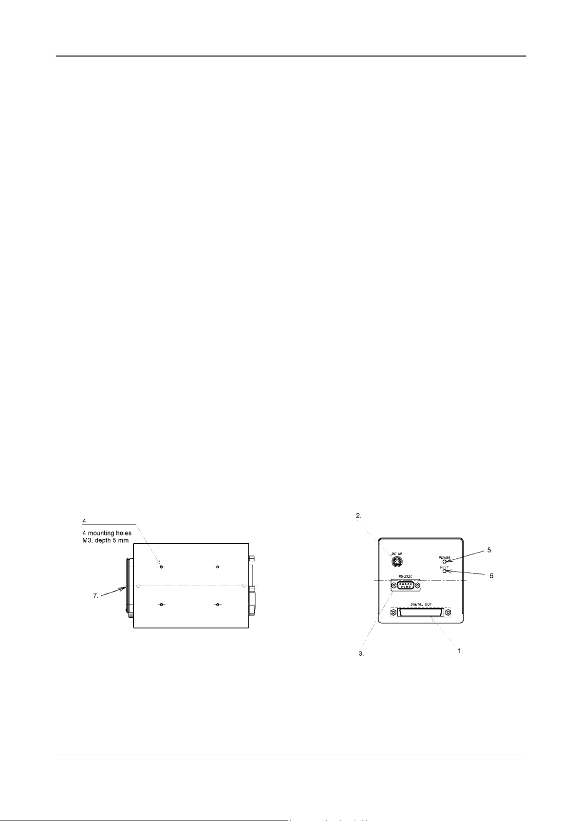
4. Locations and Functions
1. Interface connector 5. Power LED
2. Power connector 6. Busy LED.
3. RS-232C connector 7. Lens mount
4. Mounting holes
Fig. 1. Locations
- 2 -
Page 4
CV-L105
5. Pin Assignment
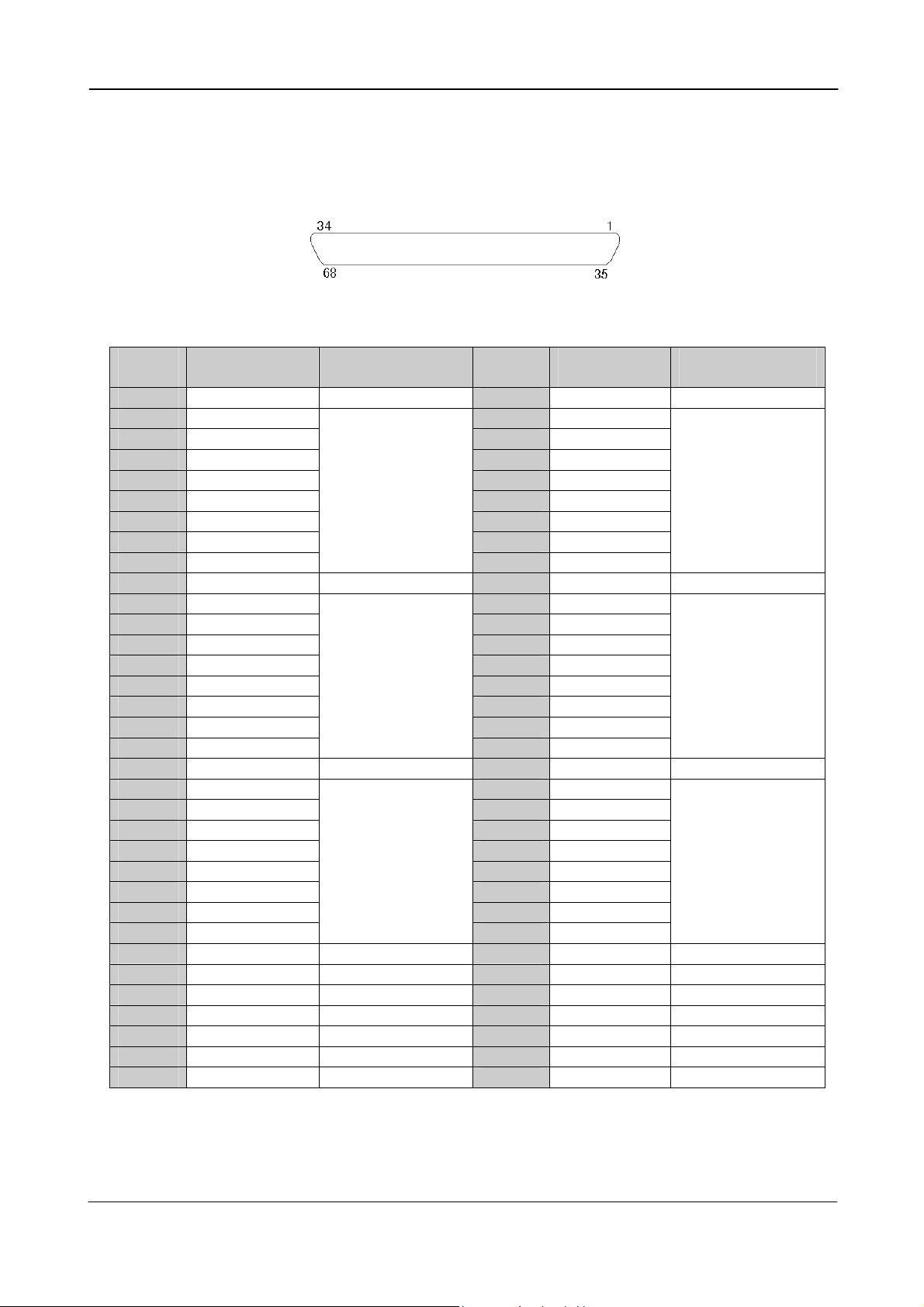
5.1. 68-pin Digital interface connector
(Digital video, control signals, trigger input)
Fig. 2. 68-pin digital interface. (Seen from camera rear.)
Pin
number Signal
Remarks
Pin
number Signal
Remarks
1 GND 35 GND
2 +RD7 out 36 -RD7 out
3 +RD6 out 37 -RD6 out
4 +RD5 out 38 -RD5 out
5 +RD4 out 39 -RD4 out
6 +RD3 out 40 -RD3 out
Red Data out. LVDS
Red Data out. LVDS
7 +RD2 out 41 -RD2 out
8 +RD1 out 42 -RD1 out
9 +RD0 out
10 BIN in
Control inp. TTL *)
43 -RD0 out
44 NC
11 +GD7 out 45 -GD7 out
12 +GD6 out 46 -GD6 out
13 +GD5 out 47 -GD5 out
14 +GD4 out 48 -GD4 out
15 +GD3 out 49 -GD3 out
Green Data out. LVDS
Green Data out. LVDS
16 +GD2 out 50 -GD2 out
17 +GD1 out 51 -GD1 out
18 +GD0 out
19 +EXT TRIG in
LVDS in
52 -GD0 out
53 -EXT TRIG in
LVDS in
20 +BD7 out 54 -BD7 out
21 +BD6 out 55 -BD6 out
22 +BD5 out 56 -BD5 out
23 +BD4 out 57 -BD4 out
24 +BD3 out 58 -BD3 out
Blue Data out. LVDS
Blue Data out. LVDS
25 +BD2 out 59 -BD2 out
26 +BD1 out 60 -BD1 out
27 +BD0 out
28 NC
29 GND
30 RS-232 on/off
31 PIXEL RATE in
32 +STROBE out
33 +LEN out
34 GND
Control inp. TTL *)
Control inp. TTL *)
LVDS out
LVDS out
61 -BD0 out
62 NC
63 GND
64 NC
65 NC
66 -STROBE out
67 -LEN out
LVDS out
LVDS out
68 GND
*) The control inputs are TTL and it has 4.7 kΩ pull up to +5V.
The camera connector part number is Hirose DX10A-68S.
The connector to use on the cable side is Hirose DX31A-68P with back shell DX68-CV1
- 3 -
Page 5
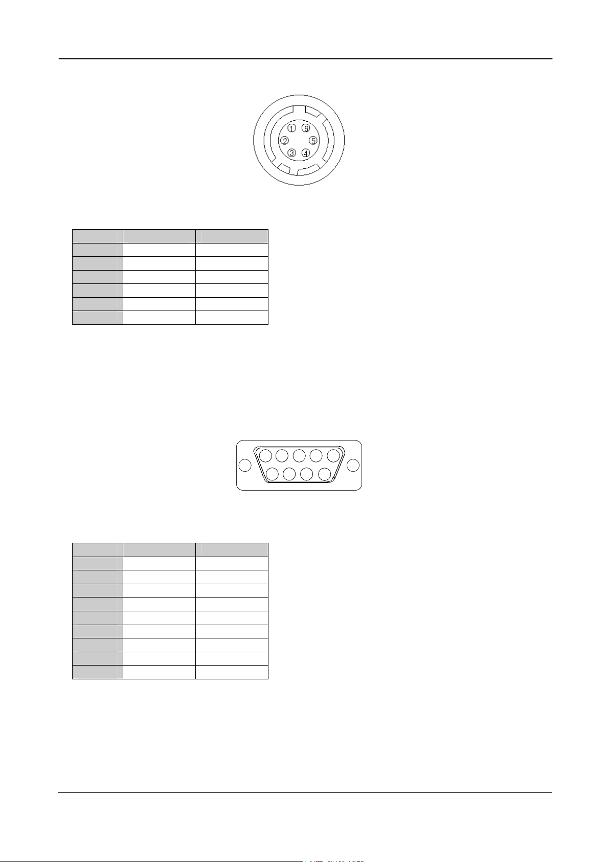
5.2. 6-pin Hirose connector (Power)
CV-L105
Fig. 3. 6-pin Hirose. (Seen from camera rear.)
Pin no. Signal Remarks
1 NC
2 NC
3 GND Power GND
4 GND Power GND
5 NC
6 +12V DC in + Power in
The camera connector part number is Hirose H10A-7R-6P. (Male).
The mating connector to use on the cable side is Hirose HR10A-7P-6S
5.3. 9-pin DSUB connector (RS-232C)
2 3 4 5
1 22 33 44 55
11
6
6 7 8
66 77 88
66
Fig. 4. 9-pin DSUB for RS-232C. (Seen from camera rear.)
Pin no. Signal Remarks
1 NC
2 TXD To PC
3 RXD From PC
4 NC
5 GND
6 NC
7 NC
8 NC
9 NC
The connector on the camera is a 9-pin DSUB male connector. The cable to the PC is a straight
through RS-232C cable.
- 4 -
Page 6
CV-L105
Ω
5.4. Input and Output Circuits
Video outputs, timing outputs, trigger input and control inputs are found on the 68 pin LVDS
connector.
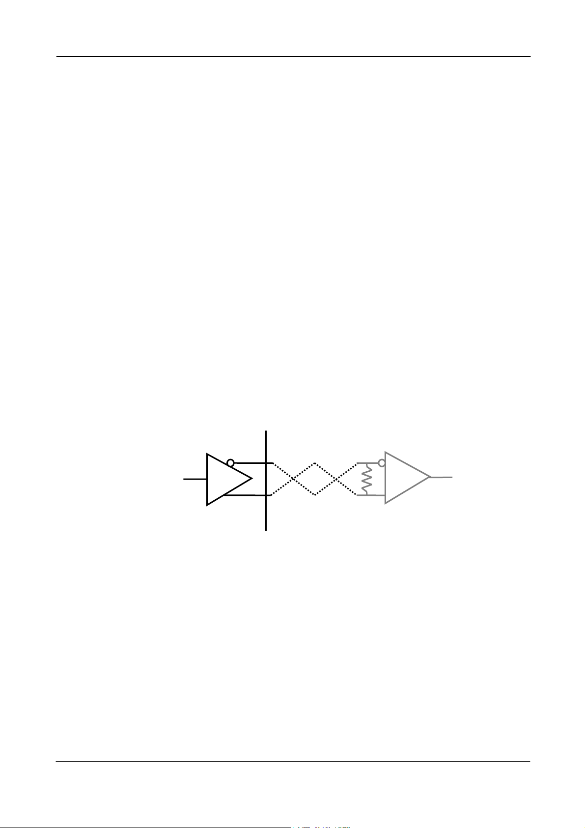
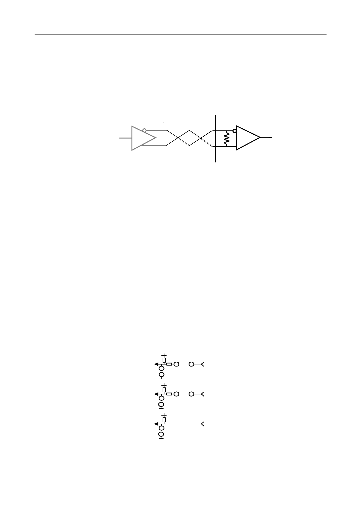
5.4.1. Video output
The digital EIA-644 LVDS output is constructed as follows:
Red channel video output
+RD0 to +RD7 Bits 0 to 7 positive side of the differential signal
-RD0 to –RD7 Bits 0 to 7 negative side of the differential signal
Green channel video output
+GD0 to +GD7 Bits 0 to 7 positive side of the differential signal
-GD0 to –GD7 Bits 0 to 7 negative side of the differential signal
Blue channel video output
+BD0 to +BD7 Bits 0 to 7 positive side of the differential signal
-BD0 to –BD7 Bits 0 to 7 negative side of the differential signal
Bit 0 is LSB. Bit 7 is MSB.
STROBE This signal is used to latch the digital video into the frame grabber.
LEN Line enable, this signal is high during the read-out of the valid digital
video.
DS90C031
100
Camera
Twisted pair
Fig. 5. Output driver circuit for Video, STROBE and LEN signals
DS90C032
Image capture
- 5 -
Page 7
CV-L105
g. 6. Input receiver circuit for
G
5.4.2. Trigger input
The camera is triggered by an EIA-644 LVDS input signal pair.
(+EXT TRIG in/ -EXT TRIG in (on pin #19 and pin #53)).
Depending on the configuration of the camera, this input can provide operation in 4 modes:
Internal Trigger. Scan mode.
Internal Trigger. Shutter mode.
External Trigger. Scan mode.
External Trigger. Shutter mode.
DS90C031
Image capture system
Fi
Twisted
5.4.3. Binning select input
This input on pin #10 (internal jumper JP1=short, JP2=open, JP4=open and RS232C disabled)
allows external equipment, such as a frame grabber, PLD or similar to enable the horizontal
binning function. The input circuit accepts TTL levels. It has 4.7 kΩ pull up to +5V. Open for no
binning.
For configuration please refer to 7.2 and 7.3.
DS90C032
100
Camera
EXT TRI
5.4.4. Pixel rate select input
This input on pin #31 (internal jumper JP 5 open and RS232C disabled) allows external
equipment, such as a frame grabber, PLD or similar to select the pixel rate. The input circuit
accepts TTL levels. It has 4.7 kΩ pull up to +5V. Open for 30 MHz.
For configuration please refer to 7.2 and 7.3.
5.4.5. RS-232C on/off (enable/disable) This input on pin #30 (internal jumper JP3=short, JP4=open.
(Factory settings, JP3=open, JP4=short.) )
allows the RS-232C function to be disabled. It is useful when the camera is operated in an
environment with RFI fields are present. The input circuit accepts TTL levels. It has 4.7 kΩ pull
up to +5V. Open for RS232C enabled.
For configuration please refer to 7.2 and 7.3.
JP1
JP1
JP2
JP2
JP2
JP4
JP4
JP4
JP1
JP3
JP3
JP3
#10
#10
#10
#30
#30
#30
Bin
Bin
Bin
RS-232
RS-232
RS-232
Clk
Clk
Clk
JP5
JP5
JP5
#31
#31
#31
Fig. 7. Control input principle
- 6 -
Page 8

CV-L105
p
p
6. Functions and Operations
6.1. Principle of operation
A line scan camera works according to the same principle as a fax machine, also sometimes
referred to as a “push broom” operation.
It captures a single line at a time (horizontal), and requires either the object or the camera to
be moving to create the vertical direction of the image.
Fig. 8. The principle of line scan.
A 3CCD line scan camera follows the exact same principle, with the added complexity of three
CCD sensors mounted on a dichroic prism. The three CCD sensors are aligned on the prism in
such as way, that they all view the same part of the object. This is referred to as co-site
sampling. Figure 4 shows the construction of the prism, and how the CCDs are aligned.
IR-cut
Fig. 9. 3 CCD prism construction.
Area
Blue
ixel
Green
Red
ixel
- 7 -
Page 9

CV-L105
Example of a camera set-up, with an encoder.
When using a line scan camera together with an encoder, it is crucial to calculate the required
specifications of the encoder in order to maintain the same aspect ratio in both vertical and
horizontal resolution.
The horizontal resolution is given by the number of pixels in the 3CCD camera.
The vertical resolution is given by the pulses generated by the encoder.
Example:
The width of the object to be scanned is 1000 mm.
This means that each pixel “projected” on the object represents a square of 0.488mm.
In order to maintain the same vertical resolution, the encoder needs to generate 2048 pulses,
for a travel of 1000 mm.
With a max line frequency at 14.285 lines/sec. the vertical scanned length is
0.488 mm x 14285 = 6971 mm/sec.
Horizontal
Resolution
Vertical
Resolution
CV-L105
PC with
Frame
Encoder
Fig. 10. Specifying an encoder.
- 8 -
Page 10

CV-L105
6.2. Trigger modes
Internal Trigger. Scan mode.
The camera will operate continuously with
its internal trigger.
The exposure is equal to the scanning time
set by the SCAN parameter via RS-232C only.
SHUTTER parameter has no meaning here.
SCAN value 150 µs through 32.5 ms.
Internal Trigger. Shutter mode.
The camera will operate continuously with
its internal trigger.
The scanning time is set by the SCAN
parameter via RS-232C only.
The exposure is set by the SHUTTER
parameter via RS-232C only.
SCAN value 150 µs through 32.5 ms.
SHUTTER value 1 µs through 32.35 ms.
External Trigger. Scan mode.
For every EXT TRIG input the ongoing
integration period is terminated and charge
is read out. At the same time it starts a new
cycle.
The exposure time is therefore dependant of
the line rate.
SHUTTER and SCAN parameters has no
meaning here.
Trigger pulse width (high period) >4 clk. *)
Trigger interval >2120 clk to ∞
External Trigger. Shutter mode.
The exposure time is governed by the low
period of the EXT TRIG signal. Exposure starts
at the falling edge of the EXT TRIG signal and
ends with the rising edge. The integration
time is independent of the line rate.
SHUTTER and SCAN parameters has no
meaning here.
Trigger pulse width (high period) >4 clk. *)
Exposure time (low period) >2102 clk to ∞
*) 1 clk is 33.3 ns for 30 MHz clock
1 clk is 66.6 ns for 15 MHz clock
Fig. 11. Internal and external trigger modes.
Exposure
Exposure
Data out
Data out
LEN
LEN
Exposure
Exposure
Data out
Data out
LEN
LEN
Trigger
Trigger
Exposure
Exposure
Data out
Data out
LEN
LEN
Trigger
Trigger
Exposure
Exposure
Data out
Data out
Exposure ti me = SCAN value
Exposure ti me = SCAN value
Scan interval = SCAN value
Scan interval = SCAN value
Exposure ti me
Exposure ti me
Exposure time
Exposure time
= SHUTTER value
= SHUTTER value
Exposure time
Exposure time
- 9 -
Page 11

CV-L105
6.2.1. Internal Trigger. Scan mode.
In this mode, the camera does not require an EXT TRIG signal to be issued to the camera. The
line rate (scan rate) is generated inside the camera. The camera will operate continuously with
its internal trigger.
The exposure time is equal to the scanning time set by the SCAN parameter via RS-232C.
The permitted range for the scan rate is 151 µs to 32.5 ms (corresponds to 6.6 kHz to 30 Hz).
SHUTTER parameter has no function here.
To use this mode:
Set function: Trigger Internal
Mode SCAN
SHUTTER value No function
SCAN value 151 µs through 32.5 ms
Clock, Binning and other functions
Input:
Important notes on using this mode:-
• It is only recommended to use this mode when there is not change of speed in the object
being scanned. If the speed of the object changes, the aspect ratio in the vertical
(scanning) direction will change.
•
Exposure
Exposure
Data out
Data out
LEN
LEN
Exposure time = SCAN value
Exposure time = SCAN value
30 MHz 1t=33.3 ns
15 MHz 1t=66.6 ns
Value in ( ) is for Binning
Fig. 12. Timing for internal scan mode
- 10 -
Page 12

CV-L105
6.2.2. Internal Trigger. Shutter mode.
In this mode, the camera does not require an EXT TRIG signal to be issued to the camera. The
line rate (scan rate) is generated inside the camera. The camera will operate continuously with
its internal trigger.
The scanning interval is equal to the time set by the SCAN parameter.
The exposure time is equal to the Shutter time set by the SHUTTER parameter via RS-232C.
The permitted range for the scan rate is 151 µs to 32.5 ms (corresponds to 6.6 kHz to 30 Hz).
The permitted range for the exposure time, SHUT value, is 1 µs up to (SCAN time – 150 µs).
(Always less than SCAN.)
To use this mode:
Set function: Trigger Internal
Mode SCAN
SHUTTER value 1 µs up to 32.35 m
SCAN value 151 µs through 32.5 ms
Clock, Binning and other functions
Input: Ext. trigger through the LVDS connector
Important notes on using this mode:-
• It is only recommended to use this mode when there is not change of speed in the object
being scanned. If the speed of the object changes, the aspect ratio in the vertical
(scanning) direction will change.
Scan interval = SCAN value
Exposure
Exposure
Data out
Data out
LEN
LEN
Scan interval = SCAN value
Exposure time
Exposure time
= SHUTTER value
= SHUTTER value
s
30 MHz 1t=33.3 ns
15 MHz 1t=66.6 ns
Value in ( ) is for Binning
Fig. 13. Timing for internal shutter mode
- 11 -
Page 13

CV-L105
6.2.3. External Trigger. Scan mode.
In this mode, the camera requires an EXT TRIG signal to be issued to the camera. The trigger
signal is typical taken from an encoder. The exposure time is equal to the trigger interval. On
the EXT TRIG input positive going edge the ongoing integration period is terminated and charge
is read out. At the same time it starts a new cycle. The exposure time is therefore dependant of
the line rate.
SHUTTER and SCAN parameters has no function here.
The permitted range for the trigger interval is >2120 clk to ∞.
Max scan rate is 14285 lines per second.
Trigger width should be >4 clk.
To use this mode:
Set function: Trigger External
Mode SCAN
SHUTTER value No function
SCAN value No function
Clock, Binning and other functions
Input: Ext. trigger through the LVDS connector
Important notes on using this mode:-
• It is only recommended to use this mode when there is not change of speed in the object
being scanned. If the speed of the object changes, the exposure time change.
• Do not apply a new trigger before the previous result has been read out. >2120 clk.
30 MHz 1t=33.3 ns
15 MHz 1t=66.6 ns
Value in ( ) is for Binning
Fig. 14. Timing for external trigger scan mode
- 12 -
Page 14

CV-L105
6.2.4. External Trigger. Shutter mode.
In this mode, the camera requires an EXT TRIG signal to be issued to the camera. The trigger
signal is typical taken from an encoder. The scanning time is equal to the trigger interval. The
exposure time is equal to the trigger low period (pulse width). For every EXT TRIG input negative
going edge an integration period starts. It is terminated and charge is read out on the trigger
positive going edge. The exposure time is therefore independant of the line rate.
SHUTTER and SCAN parameters has no function here.
The permitted range for the trigger interval is >2120 clk to ∞.
Max scan rate is 14285 lines per second.
To use this mode:
Set function: Trigger External
Mode SHUTTER
SHUTTER value No function
SCAN value No function
Clock, Binning and other functions
Input: Ext. trigger through the LVDS connector
Important notes on using this mode:-
• It is only recommended to use this mode when there is not change of speed in the object
being scanned. If the speed of the object changes, the exposure time change.
• Do not apply a new trigger before the previous result has been read out. >2120 clk.
30 MHz 1t=33.3 ns
15 MHz 1t=66.6 ns
Value in ( ) is for Binning
Fig. 15. Timing for external trigger shutter mode
- 13 -
Page 15

CV-L105
6.3. Other functions
6.3.1. Binnig
Binning is a function where the signal from two neighbour pixels are added and read out as a
single pixel. The sensitivity will be double, but the resolution will be the half. The binning
function has no influence on the internal scan rate and shutter setting.
The function can be selected by RS-232C, internal jumper setting or on the I/F connector pin
#10.
For configuration please refer to 7.2 and 7.3.
6.3.2. Pixel rate
The camera has 2 pixel clock frequencies, 30 MHz and 15 MHz. The pixel rate function selects
the pixel clock for the data read out. The function has no influence on the internal scan rate and
shutter setting. The max. scan rate with external trigger depends of the pixel clock.
The function can be selected by RS-232C, internal jumpers or on the I/F connector pin #31.
For configuration please refer to 7.2 and 7.3.
6.3.3. RS-232C on/off
This function makes it possible to disable the RS-232C input. It is useful when the camera is
operated in an environment with RFI fields are present. When RS-232C is disabled, the binning
and pixel rate can be changed by inputs on the I/F connector.
The function can be selected by internal jumpers or on the I/F connector pin #30.
For configuration please refer to 7.2 and 7.3.
6.3.4. Offset and Gain
Inside the camera there are potentiometers to adjust red, green and blue offset and gain.
They are used for the factory setting of the color balance. This is done for 3100K color
temperature. Other adjustments can be done with the potentiometers. It is not recommended to
torch the green gain and offset potentiometer, as they are the reference.
The adjustment is only for the factory setting. It has no function in the 4 user defined camera
configurations and settings.
6.3.5. LED on rear
On the camera rear two LED indicators are found. The LED marked POWER will indicate that the
power supply is on. The lower LED marked BUSY will light when external trigger is applied.
- 14 -
Page 16

CV-L105
7. Configuring the Camera
All configuration of the CV-L105 camera is done via the RS-232C port, which is factory setting.
Binning and pixel rate settings can also be controlled by TTL signals into the interface connector
or internal jumpers. From the factory, the camera will start up with the factory default.
The factory setting is as follows:
Clock 30 MHz
Binning 2048 (Off)
Trigger Internal
Mode Scan
Scan time 32.350 msec
RGB gain and offset To 3100K color balance (by internal potentiometers)
The factory settings cannot be changed by user.
There are 4 user defined configurations, which can be programmed by RS-232C and used as
initial default settings.
7.1. RS-232C control.
Communication setting.
1 CD
Baud Rate 9600 bps
Data Length 8 bit
Start Bit 1 bit
Stop Bit 1 bit
RS 232C cable
CAMERA
CAMERA
TXD
TXD
RXD
RXD
GND
GND
Parity None
Xon/Xoff Control None
Fig. 16. RS-232C cable.
JAI provides a comprehensive software configuration tool, to configure the different functions of
the camera.
The CV-L105 Camera Control Tool for Windows 98/NT/2000 can be downloaded from
www.jai.com (For not released versions only from JAI Partner Site).
The control tool contents a camera control program and tools for making your own program. The
program has a help function, which describes functions, and make it easy to use.
Fig. 17. Camera Control Tool
For the integrator and experienced user, the Camera Control Tool is much more than a program
with a window interface- It also provides an easy and efficient ActiveX interface built for MS
Windows 98, ME, NT and 2000. The OCX interface has the ability to connect to the camera using
the serial interface of the PC by reading and writing properties for the camera. This integration
requires simple programming skills within Visual Basic, Visual C++ or similar languages in a
Microsoft Windows environment.
1 CD
4 DTR
4 DTR
6 DSR
6 DSR
2 RXD
2 RXD
3 TXD
3 TXD
5 GND
5 GND
7 RTS
7 RTS
8 CTS
8 CTS
9 CI
9 CI
9 pin
9 pin
D-con
D-con
PC COM
PC COM
PORT
PORT
- 15 -
Page 17

CV-L105
Fig. 18. Shutter window
7.1.1. Clock Select
With Clock Select two speeds can be selected, 15 MHz or 30 MHz.
The 15 MHz operation will limit the maximum line rate (scan rate) to 7 172 Hz. It is
recommended when a cable length of more than 20 metres is used or in applications where high
RFI fields may be experienced.
7.1.2. Binning
With Binning set to 2048 the full resolution of the CCD sensors is 2048 pixels. If a higher
sensitivity is required, and a reduced resolution can be accepted, the binning function can be
selected by switching to 1024. As the readout section of the CCD sensor output, 2 adjacent
pixels are added and read out as one single pixel.
The STROBE frequency is divided by 2 when the camera is operated in 1024 binning mode.
7.1.3. Trigger Mode
With Trigger Mode to Internal, the camera is configured to generate the trigger pulse
internally. The Scan time and Shutter Time need to be configured for proper operation in this
mode. In External mode, the camera is configured to accept an EXT TRIG pulse.
See also 6.2. Trigger modes.
7.1.4. Shutter/Scan Mode
With Internal trigger and Shutter/Scan Mode in Shutter mode, the camera will be set to expose
for a pre-defined period of time set by Shutter Time. The scan interval (or scan rate) is set by
Scan Time. In Scan mode, the exposure time is the same as the Scan time.
With External trigger and Shutter/Scan Mode in Shutter mode, the exposure is equal to the
trigger low period. In Scan mode the exposure to the time interval between the external trigger
pulses.
See also 6.2. Trigger modes.
7.1.5. Shutter/Scan Time
The Shutter/Scan Time controls the shutter time and scan time for internal trigger mode.
The range of setting for the Shutter Time is 1 µs to (Scan Time – 150 µs).
The range of Scan Time is 151 µs to 32.35 ms.
Example, if Scan Time is set to 300 µs the range of setting is up is 300 µs – 150 µs = 150 µs.
The Shutter/Scan Time control has no function in external trigger mode.
- 16 -
Page 18

7.1.6. Gain and offset adjustment
CV-L105
Fig. 19. Gain and Offset window
The individual gain and offset setting of each color is possible. This is required for adapting the
white balance temperature for the 4 user configuration areas. For the factory default this
setting has no function. It can only be adjusted with the internal potentiometers.
The range of these settings is 0 – 255.
7.1.7. Communication and files
The communication between the PC and the camera is set up and controlled from the
communication window.
The camera settings and configuration can be read into the 4 user areas in the camera EEPROM
or to files from this window. Settings stored in files can be read and transferred to the program
and read into the camera. For detailed descriptions, please download the camera control tool
from www.jai.com and read the help description.
Fig. 20 Communication and File windows
- 17 -
Page 19

CV-L105
7.2. Configuration via I/F connector and jumpers
The binning function, pixel rate and RS-232C function can be controlled by TTL inputs on the
68pin Hirose interface connector and with jumper settings.
Below table describe the possible states of these inputs. Please refer to fig. 7. for principle.
RS-232C contr. Binning Clock
Function
RS-232C control only O S H O O H O H
RS-232C enable/disable
by I/F pin #30
Binning fixed at 1024 by JP2 O S H
Binning select by I/F pin #10
Pixel clock select by JP5
Pixel clock select by I/F pin
#31
O = jumper open
S = jumper short
H = input high. ( open. 5V by the internal 4.7 kΩ pull-up resistor)
L = input low. (closed to GND)
x = do not care
JP3 JP4
S O
S O H
S O H x x H
Pin
#30 JP1 JP2
L
O O H O H
H
S O
Pin
#10 JP5
x H
H
L
O
S
O
Remarks
Pin
#31
Factory setting. RS-232C enabled
#30 low for RS-232C enabled
#30 high for RS-232C disabled
JP2 closed for 1024
#10 high for 2048
#10 low for 1024
JP5 open for 30 MHz
H
JP5 closed for 15 MHz
#31 high for 30 MHz
H
#31 low for 15 MHz
L
RS-232C
disabled
Set by
jumper
& pin
7.3. Potentiometers and jumpers placing
There are 5 solder jumpers on the main board (PK8234B), which are accessible for the user.
On the board (PK8235B) 7 potentiometers are found. The top one marked A/D is for factory
adjustment. Do not touch it.
The red, green and blue gain and offset potentiometers is factory adjusted to white color
balance at 3100K. It is used in factory setting configuration. As the green gain and offset is
reference, do not touch it.
Top
A/D offset
R gain
R offset
G gain
G offset
B gain
B offset
JP4 JP5 JP2 P1 JP3
Fig. 21. Potentiometers and jumpers placing
- 18 -
Page 20

CV-L105
8. External Appearance and Dimensions
Fig. 22. Outlines
- 19 -
Page 21

CV-L105
9. Specifications
9.1. Specifications table
Specifications CV-L105
Scanning system
Pixel clock
Line rate (scan rate)
CCD sensor
Sensing area
Effective pixels
Pixels in video output
Cell size
Prism block
CCD alignment precision
Sensitivity on sensor
Radiometric at 3100K
Sensitivity on sensor
Photometric at 3100K
S/N ratio
Video output
Gain range
Trigger input
STROBE output
LEN output
Trigger modes
Functions controlled by input
signal on interface connector
Functions input
Functions controlled by RS232C
Communication baud rate
Diagnostics
Operating temperature
Humidity
Storage temp./humidity
Lens mount
Power
Dimensions
Weight
Up to 7172 lines/sec at 15 MHz, and up to 14285 lines/sec at 30 MHz
3 x 2048 line scan sensors mounted on an RGB prism
Dichroic beam splitter. Centre wavel. Red 630 nm, Green 535 nm, Blue 450 nm
400 Lux. (Exposure time 1 msec. Max. gain, 100% video on green)
3 x 8 bit EIA-644 Low Voltage Differential Signalling LVDS.
(for latching video into frame grabber) EIA-644 LVDS
Continuous, Pulse Width Control, Edge Pre-select
Pixel clock select, Binning, Trigger mode, Scan rate, Shutter speed, individual RGB gain,
15 or 30 MHz, user selectable
28.7 mm x 14 µm
14 µm x 14 µm
Typ. 0,5 pixel, Max 1 pixel
6.7 mV/nj/cm2. (7.2 LSB/nj/cm2 at 8 bit)
15 MHz. R: 53 dB, G: 56 dB, B: 50 dB
30 MHz. R: 47 dB, G: 50 dB, B: 44 dB
Based on NS DS90C032.
EIA-644 LVDS. Based on NS DS90C031
(valid video duration) EIA-644 LVDS
Pixel rate and binning
RS-232C control enable/disable
TTL levels. Internal 4.7 kΩ pull-up
individual RGB offset.
LED for power, LED for trigger
-5ºC to +45ºC
20 - 80% non-condensing
-25ºC to +60ºC/20 - 80% non-condensing
Nikon F-mount
12V DC ± 5% 12W (1A)
90 x 90 x 123 mm (HxWxD)
Line scan
3 x 2144
3 x 2048
12 dB
9600
1100 g
9.2. Spectral Sensitivity
1.0
B G R
0.8
IR stop
0.6
0.4
0.2
Relative transmission
0.0
400 500 600 700 800
Wave length (nm)
Fig. 23. Spectral sensitivity.
- 20 -
Page 22

10. Users Record
CV-L105
Camera type: CV-L105
Revision: (Revision A)
Serial No. ……………..
Software version. ……………..
For camera revision history, please contact your local JAI distributor.
Users Mode Settings.
Users Modifications.
DECLARATION OF CONFORMITY
AS DEFINED BY THE COUNCIL DIRECTIVE
89/336/EEC
EMC (ELECTROMAGNETIC COMPABILITY)
WE HEREWITH DECLARE THAT THIS PRODUCT
COMPLIES WITH THE FOLOWING PROVISIONS APPLYING TO IT.
EN-50081-1
EN-50082-1
Company and product names mentioned in this manual are trademarks or registered trademarks of their respective owners.
JAI A-S cannot be held responsible for any technical or typographical errors and reserves the right to make changes to products and
documentation without prior notification.
JAI A-S, Denmark JAI Corporation, Japan JAI America.Inc., USA
Produktionsvej 1, 2600 Glostrup German Industry Center 800 West Cummings Park
Copenhagen, Denmark 1-18-2 Hakusan, Midori-ku Woburn, MA 01801
Phone +45 4457 8888 Yokohama, Suite 1250
Fax +45 4491 8880 Kanagawa 226-0006, Japan Phone (Toll-Free)
www.jai.com Phone +81 45 933 5400 +1 877 472-5909
Fax +81 45 931 6142 www.jai.com
www.jai.com
- 21 -
 Loading...