

Page 1

Compact Monochrome Megapixel
Progressive Scan Camera
CV-A1-20
Operation Manual
Camera: Revision B
Manual: Version 1.1
A1-20manBoct08.doc
JPT 08-10-03
Page 2

CV-A1-20
Table of Contents
1. General......................................................................................................... 2
2. Standard Composition ....................................................................................... 2
3. Main Features ................................................................................................. 2
4. Locations and Functions..................................................................................... 3
5. Pin Assignment................................................................................................ 4
5.1. 12-pin Multi-connector (DC-IN/VIDEO OUT, EXT.HD/VD IN) .................................... 4
5.2. 6-pin Multi-connector (TRIGGER).................................................................... 4
5.3. Input and Output Circuits ............................................................................ 5
5.3.1. Video output ..................................................................................... 5
5.3.2. Trigger input ..................................................................................... 5
5.3.3. HD and VD input................................................................................. 5
5.3.4. HD, VD, PCLK, WEN and EEN output .........................................................5
5.4. CV-A1 Block Diagram .................................................................................. 6
6. Functions and Operations ................................................................................... 6
6.1. Basic functions ......................................................................................... 6
6.2. Input-output of HD/VD Signals ...................................................................... 8
6.3. Continuous Operation (Non triggered) ............................................................. 9
6.4. External Trigger Modes ............................................................................. 10
6.5. Edge Pre-select Mode ............................................................................... 11
6.6. Pulse Width Control Mode .......................................................................... 12
6.7. Frame-delay read out Mode........................................................................ 13
6.8. Long Time Exposure Mode.......................................................................... 14
6.9. Start/Stop Mode ..................................................................................... 15
6.10. Smearless Mode..................................................................................... 16
6.11. Other Functions..................................................................................... 17
7. Configuring the Camera ................................................................................... 17
7.1. RS-232C control. ..................................................................................... 17
7.2. CV-A1-20 RS-232C command list. ................................................................. 18
7.3. Camera Control Tool for CV-A1-20 ................................................................ 19
7.4. Internal Switch and Jumper Settings ............................................................. 20
8. External Appearance and Dimensions ................................................................... 20
9. Specifications ............................................................................................... 21
10. Appendix ................................................................................................... 22
10.1. Precautions.......................................................................................... 22
10.2. Typical CCD Characteristics ...................................................................... 22
11. Users Record ............................................................................................... 23
- 1 -
Page 3

CV-A1-20
1. General
The CV-A1-20 is a monochrome progressive scan 1/2” CCD camera with 1.4 Megapixel resolution.
CV-A1-20 is identical to CV-A1, but the pixel frequency is 20 MHz instead of 28.636 MHz. It is
designed for automated inspection, featuring a small housing and a wide range of unique
functions. The asynchronous trigger can be set to work in several modes, to allow such functions
as pulse width controlled shutter, programmable shutter speed and long time integration. To
obtain higher frame rates, the camera has partial scanning and both horizontal and vertical
binning.
All modes and functions can be set via an RS-232C interface, greatly reducing the need for
mechanical switches or jumpers.
CV-A1-20 Camera Control Tool for Windows 98/NT/2000 contents a camera control program and
tools for making your own program.
Camera ID, model name and user ID is present in the camera from revision B. S/N E121231.
The latest version of this manual can be downloaded from: www.jai.com
The latest version of Camera Control Tool for CV-A1-20 can be downloaded from: www.jai.com
2. Standard Composition
The standard camera composition consists of the camera main body and operation manual.
3. Main Features
• New compact size 1/2” progressive scan monochrome CCD camera
• 11 full frames 1392 (h) x 1040 (v) 4.65 µm square pixels per second
• Up to 52 fps with 1/6 partial scan.
• Double speed and double sensitivity with V binning
• 4 times normal sensitivity with H and V binning
• Internal, external HD/VD or random trigger synchronization
• Edge pre-select, programmable shutter and pulse width control trigger modes
• Start/stop mode (trigger/ext. VD) and long time exposure (ext. VD interval)
• Shutter speeds from 1/11 to 1/140,000 second in continuous mode
• Triggered shutter speed up to 1/8381 second
• Programmable shutter speed from 1.3 H to 1023.3 H
• Pulse width controlled shutter 1.3 H to 2000 H
• H synchronized or H non-synchronized accumulation in PWC mode
• Frame delay readout 1.3 H to 2000 H for pulse width controlled shutter
• Smear-less readout mode for edge pre-select and programmable shutter
• Exposure enable EEN, write enable WEN and pixel clock output
• Short ASCII commands for fast mode set-up via serial port
• Set-up by Windows 98/NT/Win2000 software via RS 232C
• Compact housing with C-mount
- 2 -
Page 4
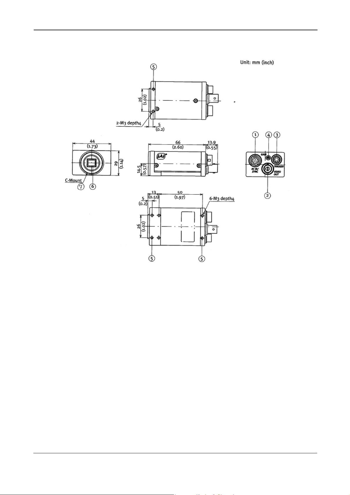
4. Locations and Functions
CV-A1-20
Fig. 1. Locations.
1. 12 pin Hirose connector for frame grabber interfacing and power (12V DC).
2. BNC connector for video output. VS 1.0 Vpp 75 Ohm.
3. 6 pin Hirose connector for trigger input and RS-232C control interface.
4. Gain potentiometer for manual gain setting.
5. Mounting holes, 8 x M3. For precision mounting use only the 4 holes located at the
forward part of the bottom plate.
6. 1/2” interline-transfer type CCD sensor.
7. Lens mount for C-mount lenses. *1)
Note: *1) Rear protrusion on the C-mount lens must be less than 10mm (0.4 inches approx.).
When IR-cut filter is used, it must be less than 7.0 mm (0.28 inches approx.).
The IR-cut filter is placed in the C-mount thread.
The C-mount IR-cut filter must be ordered separately.
- 3 -
Page 5
CV-A1-20
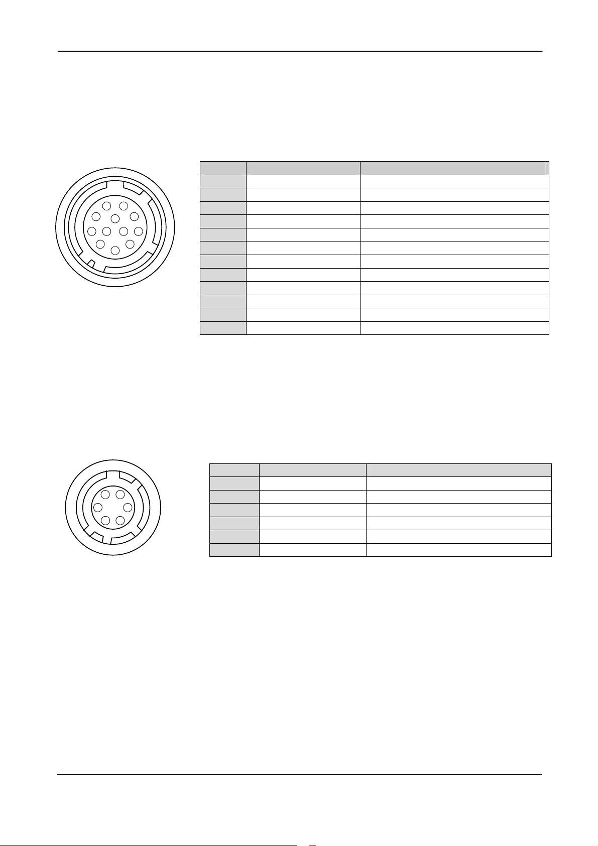
5. Pin Assignment
5.1. 12-pin Multi-connector (DC-IN/VIDEO OUT, EXT.HD/VD IN)
Type: HR10A-10R-12PB-01 (Hirose) male
Seen from rear. Pin configuration is compatible with EIAJ standard
Pin no. Signal Remarks
1 GND
2 +12 V DC input
9
1
2
3
4
8
10
11
7
12
6
5
3 GND
4 Video output
5 GND
6 HD input/HD output
7 VD input/VD output
8 GND
9 Pixel clock output
10 WEN output
11 Trigger input
12 GND
Fig. 2. 12-pin connector.
Plugs for cable: HR10A-10P-12S
Parallel with the BNC connector.
*) SW2.1 on for 75Ω. SW1.1 on for HD out.
*) SW2.2 on for75Ω. SW1.2 on for VD out.
*) JP2 short and PC=1 for pclk out.
*) GND if JP5 open and JP3 short
*) +12V DC if JP1 short and JP4 open
5.2. 6-pin Multi-connector (TRIGGER)
Type: HR10A-7R-6PB (Hirose) male
Seen from rear.
Pin no. Signal Remarks
1 TXD out
1
6
2
5
3
4
2 RXD in
3 GND
4 GND
5 Trigger input
6 EEN output
Fig. 3. 6-pin connector.
Plugs for cable: HR10A-7P-6S
Notes.
*) Alternative signals can be placed on these pins by switch or jumper settings or
RS-232C commands.
Configurations shown in Bold + italic is factory setting.
*2) EEN will be low all the time in normal continous mode (TR=0), if the selected
exposure time is longer than the frame readout time.
*) Parallel with pin 11 on 12 pin con
*) *2). WEN output if EW=1
- 4 -
Page 6
CV-A1-20
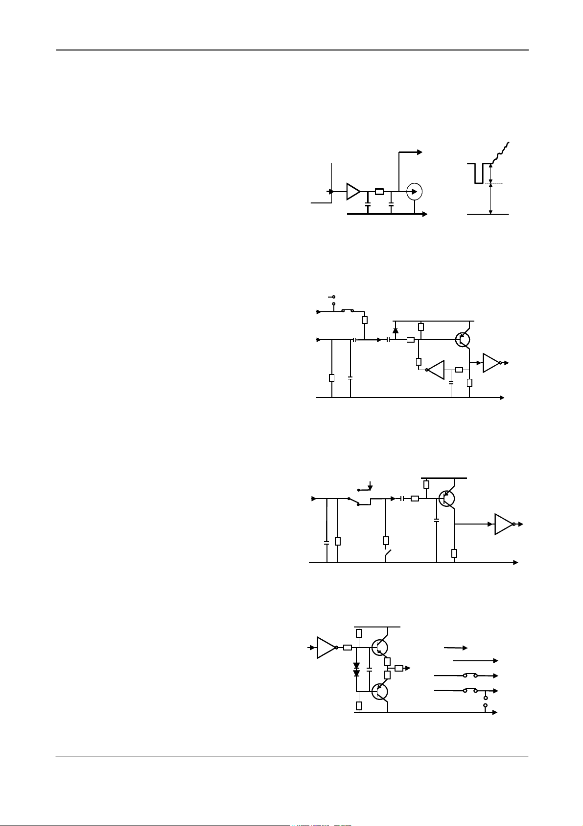
5.3. Input and Output Circuits
In the following schematic diagrams the input and output circuits for video and timing signals
are shown. For alternative connections refer to “7.4. Internal Switch and Jumper Settings.”
Jumper settings are shown as for factory default.
5.3.1. Video output
#4/12
#4/12
The video output is a 75 Ω DC coupled circuit.
The BNC connector and pin #4 on the 12-pin
connector is in parallel. Avoid double
termination. The video DC level is shown with
75 Ω termination.
In the composite signal, there are no equalize
and serration pulses in the vertical sync.
Fig. 4. Video output.
CXA1310
CXA1310
CXA1310
32
32
32
75
75
75
NC
NC
NC
#4/12
Video
Video
Video
Output
Output
Output
BNC
BNC
BNC
GND
GND
GND
300 mV
300 mV
300 mV
500 mV
500 mV
500 mV
5.3.2. Trigger input
The trigger input is AC coupled. To allow a
long pulse width, the input circuit is a flip
flop, which is toggled by the negative or
positive differentiated spikes caused by the
falling or rising trigger edges.
The trigger polarity can be changed.
Trigger input level 4 V ±2 V.
The trigger-input impedance is 1 kΩ.
JP1 and JP4 are for alternative
configuration for pin #10.
Fig. 5. Trigger input.
5.3.3. HD and VD input
The input circuit for external HD and VD
signals are shown. It can be 75 Ω
terminated by closing SW2. SW1 will switch
to output the internal HD and VD signal.
HD and VD input level is 4 V ±2 V.
Fig. 6. HD and VD input.
+12v
+12v
Trigger
Trigger
Trigger
input
input
input
#5/6
#5/6
#5/6
GND
GND
GND
VD HD
VD HD
Input/output
Input/output
1n
1n
GND
GND
1k
1k
1k
JP1
JP1
JP1
1k
1k
JP4#11/12
JP4#11/12
JP4#11/12
From VD HD
From VD HD
SW1
SW1
NC
NC
NC
output
output
100
100
100
100n
100n
100n
75
75
10µ
10µ
SW2
SW2
+
+
1k
1k
1k
33k
33k
1k2
1k2
33k
33k
33k
47p
47p
33k
33k
33k
+5V
+5V
+5V
TTL
TTL
100k
100k
100k
1k
1k
4k7
4k7
1k
+5V
+5V
1n
1n
1n
TTL
GND
GND
GND
TTL
TTL
5.3.4. HD, VD, PCLK, WEN and EEN output
Output circuit for these signals are 75 Ω
complementary emitter followers. It will
deliver a full TTL signal. JP5 and JP3 are for
alternative configuration for pin #10.
Output level ≥4 V from 75Ω. (No
termination).
The WEN polarity can be changed.
Signal on pin #6/6 can be changed.
Fig. 7. HD, VD, PCLK, WEN and EEN output.
TTL
TTL
- 5 -
10k
10k
220
220
10k
10k
10
10
10
10
+5V
+5V
WEN/ EEN
WEN/ EEN
67
67
VD, HD
VD, HD
PCLK
PCLK
WEN
WEN
JP5
JP5
JP2
JP2
SW1
SW1
JP3
JP3
#6/6
#6/6
#9/12
#9/12
#10/12
#10/12
GND
GND
Page 7
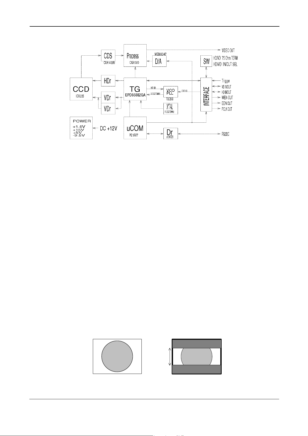
5.4. CV-A1 Block Diagram
CV-A1-20
Fig. 8. Block diagram.
6. Functions and Operations
6.1. Basic functions
Some of the primary camera functions need a general introduction before the operation modes
are described. The list below shows the primary functions from the command list.
SM Shutter Mode Normal shutter, Programmable Exposure
SH Shutter Speed Off to 1/140,000 second
PE Programmable Exposure 1.3 H to 1023.3 H
SC Scanning Format Full frame, 1/2 partial, 1/3, 1/6 partial
BI Binning Off, vertical, horizontal, vertical + horizontal
TR Trigger Mode Normal, Edge, PWC, frame delay readout
Long time exposure, start-stop, smearless (Edge)
HC HD Accumulation Sync., async.
The shutter SM can be set to normal (SM=0), where the exposure time is selected from 16 fixed
step with the command SH, or programmable exposure (SM=1). The command PE allows 1023
step with 1 line period resolution. (83.6 µs). Note that PE=0 and PE=1 results in 1.3H.
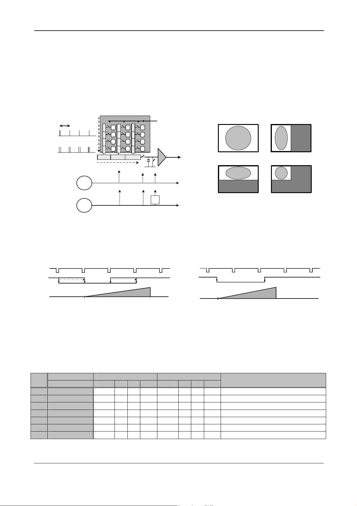
The CCD scanning format SC can be selected between full or partial scanning. With partial
scanning, only the vertical central part of the CCD sensor is read out with a higher frame rate.
The partial scan is done by a fast dump read out of the lines in the vertical ccd register down to
the top of the partial image. The partial part of the image is read out with normal speed. The
lines below the partial image are read out and dumped with a high speed.
Some signal distortion can be expected below highlighted areas, (saturated areas). It is caused
by limitation in the vertical ccd register transfer efficiency at high speed.
Imaged scene
Fig. 9. Partial scanning.
1/2 PS, 513 pixels
1/3 PS, 341 pixels
1380 pixels
1/6 PS, 171 pixels
Partial scanning.
Aspect ratio correct
- 6 -
Page 8
CV-A1-20
Binning mode BI is a function where the signal charge from 2 or more adjacent pixels are added
together and read out as one pixel. A resulting full frame with lower resolution can be read out
with a higher rate. By adding 2 pixels together, the sensitivity is doubled. The CV-A1-20 has both
vertical and horizontal binning. With V binning the pixel charge from 2 adjacent lines are added
together in the horizontal ccd register. It is done by double pulses to the vertical ccd register.
With H binning the pixel charge from 2 horizontal adjacent pixels are added together in the
sample/hold circuit after the horizontal ccd register. It is done by shifting the charge from 2
horizontal ccd cells into the sample/hold capacitor for each reset pulse.
Both vertical and horizontal binning can work together. The sensitivity is then 4 times normal.
The aspect ratio will be correct, if the sampling frequency is divided with 2. See fig. 10.
Displayed image with binning
r
No V binning
No V binning
V binning
V binning
No H binning
No H binning
H binning
H binning
r
e
f pix
f pix
f pix
f pix
e
t
t
s
s
i
i
g
g
e
e
r
r
d
d
c
c
c
c
l
l
a
a
c
c
i
i
t
t
r
r
e
e
V
V
Horizontal ccd register
Horizontal ccd register
S/H Reset
S/H Reset
S/H Reset
S/H Reset
H
H
Xsg1
Xsg1
Video out
Video out
Pclk out
Pclk out
:2
:2
Pclk out
Pclk out
H binning is 2:1. V is 2:1. Together it is a 4 :1 binning
H binning is 2:1. V is 2:1. Together it is a 4 :1 binning
Fig. 10. Binning.
The accumulation mode HC can be set to asynchronous accumulation (HC=1). The exposure in
PWC mode (TR =2) and Frame Delay readout (TR=3) will start immediately at the leading edge of
the trigger pulse without waiting for the HD. Fig. 11 and fig. 12 shows the details.
HD
Trigger
HD
Trigger
Displayed image with binning
1380 pixels
1380 pixels
1035 pixels
1035 pixels
Norma l full scanning .
Norma l full scanning .
Aspect ratio correct
Aspect ratio correct
1380 pixels
1380 pixels
501 pixels
501 pixels
Vertical binning
Vertical binning
690 pixels
690 pixels
1035 pixels
1035 pixels
Horizontal binning
Horizontal binning
690 pixels
690 pixels
501 pixels
501 pixels
V and H binning.
V and H binning.
Aspect ratio correct
Aspect ratio correct
Accum
Accum
Xb
Fig. 11. PWC H synchronous accumulation Fig 12. PWC asynchronous accumulation
In normal trigger mode (TR=0) shutter speed up to 1/140,000 sec. can be used. In all triggered
shutter modes, the shortest shutter time is limited to ≥1,3 H. (1/8381). In triggered shutter
modes with partial scan or binning, the longest shutter speed is not limited by the frame read
out time. It can be longer.
Trigger modes with possible scanning and binning combinations
Scanning Full scanning Partial scanning
TR=
0 Normal
1 Edge Pre-sel.
2 Pulse Width
3 Fr. Delay r.o.
4 Long Time int
5 Start/Stop
6 Smearless
√ Described mode
n Non-described mode combination, which will work
Binning norm. V H V+H Norm V H V+H
√ √ √ √ √
√ √ √ √ √
√ √ √ √ √
√ √ √ √ √
√
√
n n n n
√ √ √ √ √
n n n SM=0, SM=1 active
n n n SM=0, SM=1 active
n n n HC=0, HC=1 active
n n n HC=0, HC=1 active
n n n SM=0, SM=1 active
Remarks
- 7 -
Page 9

CV-A1-20
6.2. Input-output of HD/VD Signals
In the default setting the camera will accept external HD/VD signals on pin 6 and 7 of the 12 pin
Hirose connector. If external HD/VD is applied, the camera will synchronize to it. If no external
sync signals are applied, the camera will operate with its internal x-tal controlled sync. The
camera scanning system should be set to the same as the external connected sync. In fig. 13
below, the time requirements to relation between VD and HD are shown. The high to low
transition for the external VD pulse should be placed within the 68 µsec. time interval to HD.
The input is TTL level as factory setting. It can be 75 Ohm terminated by the internal switch on
the PK8342A board. SW2-1 for HD and SW2-2 for VD. On for 75 Ohm termination.
To output the internal HD/VD signals on pin 6 and 7 the internal switch SW1-1 and 1-2 on the
PK8342A board should be set ON. The output is TTL level from a 75-Ohm source.
Fig. 14 below shows the switch positions.
To use this mode:
Set function: SW 1 on PK8342A to IN for external VD/HD input. Factory default.
SW 2 on PK8342A to 75 Ω for termination of VD/HD.
SW 2 on PK8342A to TTL for TTL level for VD/HD. Factory defaults.
SW 1 on PK8342A to OUT for internal VD/HD output.
Input: Ext. VD in or int. VD out on pin 7 on 12-pin connector.
Ext. HD in or int. HD out on pin 6 on 12-pin connector.
Important notes on using this mode
External sync system should follow the camera scanning and binning system.
In trigger modes there are no continuous VD out, only after each trigger input.
Ext. HD
Ext. HD
Ext. VD
Ext. VD
9µ s9µ s
48µ s48µ s
Fig. 13. Ext. HD and ext. VD phase conditions.
>1H
>1H
HD VD
OUT
IN
75Ω
TTL
HD VD
Fig. 14. Switch positions for int./ext. sync and termination.
- 8 -
Page 10

CV-A1-20
6.3. Continuous Operation (Non triggered)
Trigger Mode Normal. TR=0. It is for applications where the camera is continuous running
without external trigger. In normal mode the shutter mode can be normal or programmable
exposure. (SM=0 SM=1). The shutter will work in all 16 steps up to 1/140,000 second or with the
programmable exposure in 1023 steps. In partial scanning and binning modes, shutter times
longer than the actual frame time has no meaning. The exposure will be equal the frame time.
If external synchronizing is used input external HD and VD signals.
To use this mode:
Set function: Trigger mode TR=0
Shutter mode “Normal” or “Programmable” SM=0, SM=1
“Shutter Speed” SH=0 through 15
“Programmable exposure” PE=1 through 1023
Input: Ext. VD on pin 7 on 12-pin connector. If used.
Ext. HD on pin 6 on 12-pin connector. If used.
Important notes on using this mode
External sync system should follow the camera scanning and binning system.
=
Fig. 15. Horizontal timing details and pixel numbering for the CCD array.
No equalize and serration pulses
Fig. 16. Vertical timing details and lines numbering for the CCD array.
1H = 83.6 µs
- 9 -
Page 11

CV-A1-20
6.4. External Trigger Modes
This camera has 6 external asynchronous trigger modes, which can be set by RS-232C commands.
1. Edge Pre-select Mode.TR=1 Pre-selected exposure. (SM=0, SM=1)
2. Pulse Width Control Mode. TR=2 Pulse width controlled exposure. (HC=0, HC=1)
3. Frame Delay read out mode. TR=3 PWC exposure read out by ext. VD. (HC=0, HC=1)
4. Long Time Exposure Mode. TR=4 Exposure is interval between ext. VD.
5. Start/stop Mode. TR=5 Exposure start by trigger and stop by ext. VD
6. Smearless Read out mode. TR=6 Pre-sel. exp. after dummy readout. (SM=0, SM=1)
The default accumulation is HD synchronously accumulation (HC=0). The accumulation starts at
the first HD after the trigger leading edge. Fig. 18. To avoid the <1H jitter caused by this delay,
synchronize the external trigger to HD as shown in fig. 17 below. The trigger level translations
should be placed inside the 8 + 4 µseconds.
In PWC mode (TR =2) and Frame Delay readout (TR=3), the accumulation mode HC can be set to
asynchronous accumulation (HC=1). The exposure will start immediately at the leading edge of
the trigger pulse without waiting for the HD. Fig. 19. below.
In Edge pre-select TR=1 and smearless TR=6, the shutter mode can be SM=0 or SM=1.
Ext. H D
Ext. H D
TRIG
TRIG
HD
HD
HD
Trigger
Trigger
Trigger
Accum
Accum
Accum
Xsub
Xsub
Xsub
Xsg
Xsg
Xsg
EEN
EEN
EEN
HD
HD
Trigger
Trigger
8µ s4µ s
8µ s4µ s
>1H
>1H
8µ s4µ s
8µ s4µ s
Fig. 17. Trigger/HD Timing.
t
t
t
1
1
t
t
2
2
t
3
3
t
t
t
t
4
5
4
5
Fig.18. Pulse Width H Synchronous Accumulation
t
t
1
1
t
t
2
2
t
t
t
t
3
3
4
4
Accum
Accum
Xsub
Xsub
Xsg
Xsg
EEN
EEN
Fig. 19. Pulse Width H Asynchronous Accumulation.
Note: Xsg and Xsub are internal signals in the camera. They are shown in the timing diagram for better understanding.
- 10 -
Page 12

CV-A1-20
6.5. Edge Pre-select Mode
The exposure starts at the first HD pulse after the trigger leading edge. It stops and is read out
after the duration of the shutter time selected. It can be the first 9 step in normal or 1023 steps
in programmable shutter. SM=0 or SM=1. Shutter selections SH ≥10 will result in 1/8381 sec. This
mode will operate with full and partial scanning and with all binning modes. Partial scanning
together with binning will work, but it is not described, and no timing diagrams are documented.
An EEN pulse will indicate the active accumulation time, and a WEN pulse indicates that the
resulting video is being read out.
To use this mode:
Set function: Trigger mode “Edge Pre-select” TR = 1
Shutter mode “Normal” or “Programmable” SM=0, SM=1
“Shutter Speed” SH=0 through 9
“Programmable exposure” PE=1 through 1023
Polarity and other functions
Input: Ext. trigger to pin 5 on 6 pin connector (or pin 11 on 12-pin connector).
Ext. HD to pin 6 on12-pin connector. (If used).
Important notes on using this mode.
• The start of exposure will start synchronized to the internal H signal. The start may be
shifted max 1H. To avoid this shift (1 H jitter), synchronize the camera to an external HD
and make sure that the trigger pulse aligns to the HD as shown in fig. 17.
• The duration of the trigger should be >1H to <2000H.
• A new trigger must not be applied before WEN is high.
• In trigger modes there are no continuous VD out, only after each trigger input.
1H = 83.6 µs
No equalize and serration pulses.
Table showing the figures for the different modes.
Scan mode
Full 10H 14H 4 to 1038 1035H 18H 11
1/2 Partial 17H 33H 271 to 783 513H 25H 20
1/3 Partial 17H 33H 357 to 697 341H 25H 28
1/6 Partial 17H 33H 442 to 612 171H 25H 46
H binning 10H 14H 4 to 1038 1035H 18H 11
V binning 10H 14H 18 to 1019 501H 18H 22
V+H binning 10H 14H 18 to 1019 501H 18H 22
A B C
CCD array line # D Effective video
E Max frame rate
fps
Remarks
Fig. 20. Timing for Edge Pre-select with partial scanning and binning.
- 11 -
Page 13

CV-A1-20
6.6. Pulse Width Control Mode
In this mode the exposure starts from the leading edge of the trigger pulse. It stops at the
trailing edge of the trigger pulse, and the resulting video is read out. The accumulation can be
either H synchronous or H asynchronous. HC=0 or HC=1. In H synchronous mode the accumulation
starts at the first HD pulse after the leading edge of the trigger. It can result in <1H jitter if the
trigger is not synchronized to H. In H asynchronous mode the accumulation starts immediately
after the leading edge of the trigger. (The internal H is not reset.)
This mode will operate with full and partial scanning and with all binning modes. Partial
scanning together with binning will work, but it is not described, and no timing diagrams are
documented. An EEN pulse will indicate the active accumulation time, and a WEN pulse
indicates that the resulting video is being read out.
To use this mode:
Set function: Trigger mode “Pulse Width Controlled” TR = 2
“H accumulation” HC=0 or HC=1
Polarity and other functions
Input: Ext. trigger to pin 5 on 6 pin connector (or pin 11 on 12-pin connector).
Ext. HD to pin 6 on12-pin connector. (If used).
Important notes on using this mode.
• With HC=0 the start of exposure will start synchronized to the internal H signal. The start
may be shifted max 1H. To avoid this shift (1 H jitter), synchronize the camera to an
external HD and make sure that the trigger pulse aligns to the HD as shown in fig. 17.
With HC=1 the exposure will start immediately. Refer to fig. 18 and fig. 19.
• The duration of the trigger can be >1H to <2000H.
• A new trigger must not be applied before WEN is high.
• In trigger modes there are no continuous VD out, only after each trigger input.
1H = 83.6 µs
No equalize and serration pulses.
Table showing the figures for the different modes.
Scan mode
Full 10H 14H 4 to 1038 1035H 18H 11
1/2 Partial 17H 33H 271 to 783 513H 25H 20
1/3 Partial 17H 33H 357 to 697 341H 25H 28
1/6 Partial 17H 33H 442 to 612 171H 25H 46
H binning 10H 14H 4 to 1038 1035H 18H 11
V binning 10H 14H 18 to 1019 501H 18H 22
V+H binning 10H 14H 18 to 1019 501H 18H 22
A B C
CCD array line # D Effective video
E Max frame rate
fps
Remarks
Fig. 21. Pulse Width Control trigger mode
- 12 -
Page 14

CV-A1-20
6.7. Frame-delay read out Mode
In this mode the exposure starts from the leading edge of the trigger pulse. It stops at the
trailing edge of the trigger pulse. The accumulation can be either H synchronous or H
asynchronous. HC=0 or HC=1. In H synchronous mode the accumulation starts at the first HD
pulse after the leading edge of the trigger. In H asynchronous mode the accumulation starts
immediately after the leading edge of the trigger. (The internal H is not reset.) The resulting
video is read out after an external VD pulse is applied. This mode will operate with full and
partial scanning and with all binning modes. Partial scanning together with binning will work,
but it is not described, and no timing diagrams are documented.
An EEN pulse will indicate the active accumulation time, and a WEN pulse indicates that the
resulting video is being read out.
To use this mode:
Set function: Trigger mode “Frame-delay read out” TR = 3
“H accumulation” HC=0 or HC=1
Polarity and other functions
Input: Ext. trigger to pin 5 on 6 pin connector (or pin 11 on 12-pin connector).
Ext. VD to pin 7 on 12-pin connector.
Ext. HD to pin 6 on12-pin connector. (If used).
Important notes on using this mode.
• With HC=0 the start of exposure will start synchronized to the internal H signal, the start
of exposure may be shifted max 1H. To avoid this shift (jitter), synchronize the camera to
an external HD and make sure that the trigger pulse aligns to the HD as shown in fig. 17.
• With HC=1 the exposure will start immediately. Refer to fig. 18 and fig. 19.
• The duration of the trigger can be>1H to<2000H.
• A new trigger must not be applied before WEN is high.
• In trigger modes there are no continuous VD out, only after each trigger input.
1H = 83.6 µs
No equalize and serration pulses.
Table showing the figures for the different modes.
Binning
Normal 4 to 1038 1035H
H 4 to 1038 1035H
V 18 to 1019 501H
V+H 18 to 1019 501H
(CCD array line #)
A
B
Fig. 22. Frame Delay read out mode
- 13 -
Page 15

CV-A1-20
6.8. Long Time Exposure Mode
The exposure time is the interval between 2 external VD pulses sent to the VD input. The
exposure starts after the input of a VD, and it ends after the next VD input, which again starts a
new exposure. The interval between the external VD pulses (exposure time) can be from V to ∞.
Thermal and dark current noise will increase by accumulation time, therefore the exposure time
is not recommended to exceed 2 seconds (or 30 V periods). The external applied sync system
should follow the camera scan system.
The long time exposure is a continuous process where each external VD pulse will synchronize
the camera, stop an exposure, start a new exposure and read out the previous accumulated
video signal.
A WEN pulse indicates that the resulting video is being read out.
To use this mode:
Set function: Trigger mode “Long Time Exposure” TR = 4
Polarity and other functions
Input: Ext. VD to pin 7 on 12-pin connector.
Ext. HD to pin 6 on12-pin connector. (If used).
Important notes on using this mode.
• Depending of the temperature, it is not recommended to use integration time >2 sec.
1H = 83.6 µs
No equalize and serration pulses.
No equalize and serration pulses.
Fig. 23. Long time exposure
- 14 -
Page 16

CV-A1-20
No equalize and serration pulses.
6.9. Start/Stop Mode
The exposure is controlled by the interval between the external trigger pulse and an external VD
pulse. The exposure start at the first HD pulse after the trigger leading edge, and it stops after
the rising edge of the VD. An EEN pulse will indicate the active accumulation time, and a WEN
pulse indicates that the resulting video is being read out.
The shortest exposure time in this mode is >1.3H.
The longest exposure time is <2000 H.
To use this mode:
Set function: Trigger mode “Start/Stop Mode” TR = 5
Polarity and other functions
Input: Ext. trigger to pin 5 on 6-pin connector (or pin 11 on 12-pin con.).
Ext. VD to pin 7 on 12-pin connector.
Ext. HD to pin 6 on12-pin connector. (If used).
Important notes on using this mode.
• The start of exposure will start synchronized to the internal H signal. The start may be
shifted max 1H. To avoid this shift (1 H jitter), synchronize the camera to an external HD
and make sure that the trigger pulse aligns to the HD as shown in fig. 17.
• The duration of the trigger should be >1H.
• A new trigger must not be applied before WEN is high.
• In trigger modes there are no continuous VD out, only after each trigger input.
1H = 83.6 µs
Fig. 24. Start/Stop mode
- 15 -
Page 17

CV-A1-20
6.10. Smearless Mode
This mode will reduce the unwanted smear signal from a highlighted scene when a short
exposure time is used. The trigger mode is like edge pre-select, but a dummy readout is
performed before the active accumulation is started. It will remove the smear above the
highlighted parts in the image, but there is still smear left below highlighted areas.
The trigger leading edge will start the dummy readout. It takes 54 H before the exposure starts.
The exposure stops and the resulting video signal is read out after the selected shutter time. It
can be the 16 step normal or 1023 step programmable. SM=0 or SM=1.
This mode will operate with full and partial scanning and with all binning modes. Partial
scanning together with binning will work, but it is not described, and no timing diagrams will be
documented. An EEN pulse will indicate the active accumulation time, and a WEN pulse
indicates that the resulting video is being read out.
To use this mode:
Set function: Trigger mode “Smearless read out” TR = 6
Shutter mode “Normal” or “Programmable” SM=0, SM=1
“Shutter Speed” SH=0 through 9
“Programmable exposure” PE=1 through 1023
Polarity and other functions
Input: Ext. trigger to pin 5 on 6 pin connector (or pin 11 on 12-pin connector).
Ext. HD to pin 6 on12-pin connector. (If used).
Important notes on using this mode.
• The start of exposure will start synchronized to the internal H signal. The start may be
shifted max 1H. To avoid this shift (1 H jitter), synchronize the camera to an external HD
and make sure that the trigger pulse aligns to the HD as shown in fig. 17.
• The duration of the trigger should be >1H to <2000H.
• A new trigger must not be applied before WEN is high.
• In trigger modes there are no continuous VD out, only after each trigger input.
No equalize and serration pulses.
Scan mode
Full 10H 14H 4 to 1038 1035H 18H 11
1/2 Partial 17H 33H 271 to 783 513H 25H 18
1/3 Partial 17H 33H 357 to 697 341H 25H 25
1/6 Partial 17H 33H 442 to 612 171H 25H 38
H binning 10H 14H 4 to 1038 1035H 18H 11
V binning 10H 14H 18 to 1019 501H 18H 20
V+H binning 10H 14H 18 to 1019 501H 18H 20
A B C
CCD array line # D Effective video
E Max frame rate
fps
Remarks
Fig. 25. Smearless Mode
- 16 -
Page 18

CV-A1-20
6.11. Other Functions.
Gain and analogue settings.
!! Do not adjust these settings unless you have knowledge to video adjustments !!
The video gain can be set to AGC or manual. In AGC mode the video level is kept constant by
the automatic gain control circuit within a 12 dB range. Normal 700 mVpp ±30 mV. The level can
be adjusted with AGC level.
In manual gain mode, either the gain level or the rear potentiometer can adjust the level.
Setup level. This setting can adjust the setup level (or black level). Normal 20 mVpp ±2 mv.
White clip level. For adjusting the wanted white clip level. Normal 800 mVpp ±30 mv.
Gamma select. Gamma can be 1 (linear) or 0.45.
Sync signal on/off. Off will remove the composite sync signal from the video signal.
Pixel clock on/off. Set to on if the pixel clock is used. To avoid interference the pixel clock out
should be off when not used.
EEN/WEN output. Will select EEN or WEN signal output on pin #6 on 6-pin connector.
Trigger polarity. Will invert the trigger-input signal.
WEN polarity. Will invert the WEN output signal.
7. Configuring the Camera
7.1. RS-232C control.
All configuration of the CV-A1-20 camera is done via the RS-232C port. The camera can be set up
from a PC running terminal emulator software, or using JAI´s camera control software.
Below is the description of the ASCII based short command protocol.
Communication setting.
1 CD
Baud Rate 9600 bps
Data Length 8 bit
Start Bit 1 bit
RS 232C cable
CAMERA
CAMERA
Stop Bit 1 bit
Parity None
Xon/Xoff Control None
Protocol.
Transmit setting to camera:
NN=[Parameter]<CR><LF> (NN is any kind of command. Capital or small letters.)
To have all communication visible on the emulator screen, start with:
EB=1<CR><LF>
The camera answers:
COMPLETE<CR><LF>
Transmit the following to have the actual parameter for a command:
NN?<CR><LF> (NN is any commands with parameters.)
The camera answers: NN=[Parameter]
Transmit the following to have the camera actual setting:
ST?<CR><LF>
The camera returns the actual parameter settings.
Transmit the following to have a command list:
HP?<CR><LF>
The camera returns a complete command list.
- 17 -
TXD
TXD
RXD
RXD
GND
GND
1 CD
4 DTR
4 DTR
6 DSR
6 DSR
2 RXD
2 RXD
3 TXD
3 TXD
5 GND
5 GND
7 RTS
7 RTS
8 CTS
8 CTS
9 CI
9 CI
9 pin
9 pin
D-con
D-con
PC COM
PC COM
PORT
PORT
Page 19

CV-A1-20
7.2. CV-A1-20 RS-232C command list.
Command Name Format Parameter Remarks
A – General settings and useful commands
EB Echo Back
EB=[Param.]<CR><LF>
0=Echo off 1=Echo on
ST Camera Status request ST?<CR><LF>
HP Online Help request HP?<CR><LF>
VN Firmware version VN?<CR><LF>
ID Camera ID request ID?<CR><LF>
MD Model name request MD?<CR><LF>
UD User ID
UD=[Param.]<CR><LF>
Save and load user text
B – Timing and shutter related commands
SC Scanning format
TR Trigger mode
SC=[Param.]<CR><LF>
TR=[Param.]<CR><LF>
0=full frame
2=1/3 partial
0=normal
2=Pulse width
4=Long time
1=1/2 partial
3=1/6 partial
1=Edge
3=Frame delay
5=Start/stop
6=Smearless
SM Shutter mode
SH Shutter speed
PE Programmable expos.
BI Binning
HC HD accumulation
SM=[Param.]<CR><LF>
SH=[Param.]<CR><LF>
PE=[Param.]<CR><LF>
BI=[Param.]<CR><LF>
HC=[Param.]<CR><LF>
0=Normal 1=Programmab.
0=Off
2=1/42
4=1/175
6=1/698
8=1/2794
10=1/14,000
12=1/56,000
14=1/112,000
0=1.3 H, 1=1.3H 1023=1023.3 H
0=off
2=horizontal
0=H synchron
accumulation
1=1/21
3=1/70
5=1/349
7=1/1397
9=1/5587
11=1/28,000
13=1/84,000
15=1/140,000
1=vertical
3=hor. + ver.
1=a-synchron
accumulation
C – Signals and polarity
SO Sync signal
PC Pixel clock
EW EEN/WEN
TP Trigger polarity
WP WEN polarity
SO=[Param.]<CR><LF>
PC=[Param.]<CR><LF>
EW=[Param.]<CR><LF>
TP=[Param.]<CR><LF>
WP=[Param.]<CR><LF>
0=no sync 1=sync on video
0=no clock out 1=clock out
0= EEN out 1=WEN out
0= active low 1= active high
0= active low 1= active high
D – Gain and analogue signals setting
AS AGC Switch
AG AGC Level
GA Manual gain Level
RP Rear Potentiometer
SU Setup Level
WC White clip Level
GS Gamma Select
AS=[Param.]<CR><LF>
AG=[Param.]<CR><LF>
GA=[Param.]<CR><LF>
RP=[Param.]<CR><LF>
SU=[Param.]<CR><LF>
WC=[Param.]<CR><LF>
GS=[Param.]<CR><LF>
0=AGC off 1=AGC on
0=low 255=high
0=low 255=high
0=manual gain 1=rear potm.
0=low 255=high
0=low 255=high
0=gamma 1 1=gamma 0.45
E – Saving and loading data in EEPROM
LD Load settings from
camera EEPROM
SA Save settings to
camera EEPROM
LD=[Param.]<CR><LF>
SA=[Param.]<CR><LF>
0=Factory data
2=User 2 area
1=User 1 area
3=User 3 area
1=User 1 area
3=User 3 area
2=User 2 area
EA EEPROM area request EA?<CR><LF>
*1) The internal pixel clock is not changed in H binning (BI=2 and BI=3). To keep the aspect ratio correct, divided the clock by
*2) If positive logic is used (TP=1), the first trigger pulse after power up will be ignored.
*3) Functions implemented from s/no E121231.
2 in the frame grabber.
Off at power up
Actual setting
Command list
3 letter version
10 characters *3)
≤10 characters *3)
≤16 characters *3)
All16 step is valid
in normal trigger
mode.
In all trigger
modes shutter
speeds higher
than 9 will result
in 1/8381
H= 83.6 µsec
*1)
a-sync. only for
TR=1 and TR=3
Should be off
when not used
Pin#6 on 6 pin
*2)
0= manual gain
Range 0 to 255
Range 0 to 255
Range 0 to 255
Range 0 to 255
Latest used data
area becomes
default at next
power up
Return latest used
area
- 18 -
Page 20

CV-A1-20
7.3. Camera Control Tool for CV-A1-20
Camera Control Tool for CV-A1-20 is in principle the same as for CV-A1, only the shutter times
are different. From www.jai.com CV-A1-20 Camera Control Tool for Windows 98/NT/2000 can be
downloaded.
The control tool contents a camera control program and tools for making your own program.
Below the different windows are shown.
Control Bar
Windows for all functions
Fig. 26. Windows from Camera Tools.
For the integrator and experienced user, the Camera Control Tool is much more than a program
with a window interface- It also provides an easy and efficient ActiveX interface built for MS
Windows 98, ME, NT and 2000. The OCX interface has the ability to connect to the camera using
the serial interface of the PC by reading and writing properties for the camera. This integration
requires simple programming skills within Visual Basic, Visual C++ or similar languages in a
Microsoft Windows environment.
- 19 -
Page 21

CV-A1-20
7.4. Internal Switch and Jumper Settings
For VD and HD input/output and termination refer to “6.2. Input-output of HD/VD Signals.”
For alternative connections of pin #10 and #11 on 12-pin connector, jumper JP1, JP2, JP3, JP4
and JP5 can be used. Refer “5.3. Input and Output Circuits.”
Jumper setting for alternative pin configuration for M-series camera emulating is shown below.
Pin # Function JP2 JP3 JP5 JP1 JP4 Remarks
9 PCLK out Short Factory default setting (EIA-J standard)
9 No connection Open
10 WEN out Open Short Factory default setting (EIA-J standard)
10 Ground Short Open
11 Ext. trigger in Open Short Factory default setting (EIA-J standard)
11 +12 Volt in/out Short Open Warning! +12 volt power out here.
Fig. 27. Jumper positions.
8. External Appearance and Dimensions
Fig. 28. Dimensions
- 20 -
Page 22

CV-A1-20
9. Specifications
Specifications CV-A1-20
Scanning system Progressive 1068 lines 11.2 frames/sec.
Pixel clock 20.00 MHz
Line frequency 11.962 kHz (1672 pixel clock/line)
Frame rate for full frame 11.2 frames/sec. (1068 lines/frame)
CCD sensor 1/2” progressive monochrome IT CCD
Sensing area for video out 6.42 (h) x 4.81 (v) mm
Effective pixels 1392 (h) x 1040 (v)
Pixels in video output 1380 (h) x 1035 (v)
Cell size
Resolution horizontal 1000 TV lines
Sensitivity on sensor 0.2 Lux, Max gain, 50% video
S/N ratio >50 dB
Video output
Gamma 1.0 – 0.45
Gain
Gain range
Synchronization Int. X-tal. Ext. HD/VD or random trigger
HD sync. input/output
Trigger input
WEN output (write enable)
EEN output (exposure enable)
Pixel clock output
Read out modes for full frame Full, 2:1 H binning, 2:1 V binning, H+V binning
Read out partial scan vertical Full, 1/2, 1/3, 1/6
Trigger Continuous, Edge pre-select, Pulse width control, frame delay
Accumulation by trigger H synchronized/ (H non synchronized. In PWC and frame delay only)
Shutter speed. Fixed
(Full frame only)
Shutter speed in trigger modes Max. 1/5587 second. (1/8381 for settings >1/5587)
Programmable exposure 1.3 H to 1023.3 H in 1 H step
Pulse width control 1.3 H to 2000 H
Long time exposure <2 sec. (Interval between ext. VD)
Start/stop exposure 1.3 H to – 2000 H
Frame delay readout PWC 1.3 H to 2000 H
Delay in frame delay readout mode < 2 seconds (Time from PWC trigger input to ext. VD input.)
Smearless readout For edge pre-select mode only
Functions controlled by internal DIP
switches
Functions controlled by
RS 232C short commands
Communication Baud rate 9600 bps
Operating temperature
Humidity 20 – 80% non-condensing
Storage temp./humidity
Power
Lens mount C-mount
Dimensions 29 x 44 x 66 mm (HxWxD)
Weight 150g
1/11, 1/21, 1/42, 1/70, 1/175, 1/349, 1/698, 1/1400, 1/2800, 1/5587, 1/14,000, 1/28,000,
1/56,000, 1/84,000, 1/112,000, 1/140,000 second
Shutter speed, shutter mode, Trigger mode, Readout mode, polarity,
Sync. on/off, Programmable exposure, Gain levels, Gamma and RS 232C Commands
-30°C to +60°C/20% - 90 % non-condensing
Spectral Sensitivity
1.0
4.65 (h) x 4.65 (v) µm
Composite VS signal, 1 Vpp, 75 Ω
Video signal 0.7 Vpp (selectable)
Manual – Automatic
Man. -3 to +12 dB. Aut. 0 to +12 dB
4 V ±2 V, 75 Ω
4 V ±2 V, 1kΩ input impedance
4 V ±2 V, 75 Ω
4 V ±2 V, 75 Ω
4 V ±2 V, 75 Ω
(Time from trigger to ext. VD)
VD input/output, HD input/output
HD, VD 75
Ω termination on/off
-5°C to +45°C
12V DC ± 10%. 1.8 W
0.8
0.6
0.4
Relative transmission
0.2
0.0
400 500 600 700 800 900
Wave lenght ( nm )
1000
- 21 -
Page 23

CV-A1-20
10. Appendix
10.1. Precautions
Personnel not trained in dealing with similar electronic devices should not service this camera.
The camera contains components sensitive to electrostatic discharge. The handling of these
devices should follow the requirements of electrostatic sensitive components.
Do not attempt to disassemble this camera.
Do not expose this camera to rain or moisture.
Do not face this camera towards the sun, extreme bright light or light reflecting objects.
When this camera is not in use, put the supplied lens cap on the lens mount.
Handle this camera with the maximum care.
Operate this camera only from the type of power source indicated on the camera.
Power off the camera during any modification such as changes of jumper and switch setting.
10.2. Typical CCD Characteristics
The following effects may be observed on the video monitor screen. They do not indicate any
fault of the CCD camera, but do associate with typical CCD characteristics.
V. Smear
Due to an excessive bright object such as electric lighting, sun or strong reflection, vertical
smear may be visible on the video monitor screen. This phenomenon is related to the
characteristics of the Interline Transfer System employed in the CCD.
V. Aliasing
When the CCD camera captures stripes, straight lines or similar sharp patterns, jagged image on
the monitor may appear.
Blemishes
Some pixel defects can occur, but this does not have en effect on the practical operation.
Patterned Noise
When the CCD camera captures a dark object at high temperature or is used for long time
integration, fixed pattern noise (shown as white dots) may appear on the video monitor screen.
- 22 -
Page 24

11. Users Record
Camera type: CV-A1-20
Revision: (Revision B)
Serial No. ……………..
Users Mode Settings
Users Modifications
CV-A1-20
DECLARATION OF CONFORMITY
AS DEFINED BY THE COUNCIL DIRECTIVE
89/336/EEC
EMC (ELECTROMAGNETIC COMPABILITY)
WE HEREWITH DECLARE THAT THIS PRODUCT
COMPLIES WITH THE FOLOWING PROVISIONS APPLYING TO IT.
EN-50081-1
Company and product names mentioned in this manual are trademarks or registered trademarks of their respective owners.
JAI A-S cannot be held responsible for any technical or typographical errors and reserves the right to make changes to products and
documentation without prior notification.
JAI A-S, Denmark
Phone +45 4457 8888
Fax +45 4491 8880
www.jai.com
JAI Corporation, Japan
Phone +81 45 440 0154
Fax +81 45 440 0166
www.jai-corp.co.jp
JAI UK Ltd., England
Phone +44 1895 821 481
Fax +44 1895 824 433
www.jai.com
JAI PULNiX Inc., USA
Phone (Toll-Free) +1 877 472 5909
Phone +1 408 747 0300
www.jaipulnix.com
EN-50082-1
- 23 -
 Loading...