

Page 1

AM-1600CL
AB-1600CL
Digital Monochrome/Color 16 megapixel
Camera with Camera Link interface
Document Version: ver.1.0
User's Manual
Page 2

AM-1600CL / AB-1600CL
- 2 -
Notice
The material contained in this manual consists of information that is proprietary to JAI Ltd.,
Japan and may only be used by the purchasers of the product. JAI Ltd., Japan makes no warranty
for the use of its product and assumes no responsibility for any errors which may appear or for
damages resulting from the use of the information contained herein. JAI Ltd., Japan reserves the
right to make changes without notice.
Company and product names mentioned in this manual are trademarks or registered trademarks of
their respective owners.
Warranty
For information about the warranty, please contact your factory representative.
Certifications
CE compliance
As defined by the Directive 2004/108/EC of the European Parliament and of the Council, EMC
(Electromagnetic compatibility), JAI Ltd., Japan declares that AM-1600CL-P, AM-1600CL-F, AB1600CL-P and AB-1600CL-F comply with the following provisions applying to its standards.
EN 61000-6-3 (Generic emission standard part 1)
EN 61000-6-2 (immunity)
FCC
This equipment has been tested and found to comply with the limits for a Class B digital device,
pursuant to Part 15 of the FCC Rules. These limits are designed to provide reasonable protection
against harmful interference in a residential installation. This equipment generates, uses and can
radiate radio frequency energy and, if not installed and used in accordance with the instructions,
may cause harmful interference to radio communications. However, there is no guarantee that
interference will not occur in a particular installation. If this equipment does cause harmful
interference to radio or television reception, which can be determined by turning the equipment
off and on, the user is encouraged to try to correct the interference by one or more of the
following measures:
- Reorient or relocate the receiving antenna.
- Increase the separation between the equipment and receiver.
-
Connect the equipment into an outlet on a circuit different from that to which the receiver is
connected.
-
Consult the dealer or an experienced radio/TV technician for help.
Warning
Changes or modifications to this unit not expressly approved by the party
responsible for FCC compliance could void the user’s authority to operate the
equipment.
Page 3

AM-1600CL / AB-1600CL
- 3 -
- Contents –
1. General..................................................................................................- 5 -
2. Camera nomenclature ................................................................................- 5 -
3. Main Features ..........................................................................................- 6 -
4. Locations and Functions..............................................................................- 7 -
5. Pin Assignment.........................................................................................- 8 -
5.1. 12-pin Multi-connector (DC-IN/Trigger) ........................................................- 8 -
5.2. Digital Output Connector for Camera Link.....................................................- 8 -
5.3. Input and output circuits .........................................................................- 9 -
5.3.1. Trigger input ..............................................................................- 9 -
5.3.2. XEEN output ...............................................................................- 9 -
5.3.3. Camera Link interface ...................................................................- 9 -
5.4. Video output through Camera Link connector .............................................. - 11 -
6. Functions and Operations .......................................................................... - 12 -
6.1. Before starting ................................................................................... - 12 -
6.2. Basic functions ................................................................................... - 12 -
6.2.1. Digital Video Output (Bit Allocation)................................................ - 12 -
6.2.2. Electronic Shutter ...................................................................... - 13 -
6.2.3. Continuous operation or triggered operation ...................................... - 13 -
6.2.4. Rear panel indicator. .................................................................. - 13 -
6.2.5. Auto-detect LVAL-sync / async accumulation ..................................... - 13 -
6.2.6. Starting pixel - Bayer color mosaic .................................................. - 14 -
6.2.7. Partial Scanning ........................................................................ - 14 -
6.2.8. Binning Functions (AM-1600CL only)................................................. - 15 -
6.3. Pre-processing Functions (overview) ......................................................... - 16 -
6.3.1. Blemish Compensation (AM-1600CL only)........................................... - 16 -
6.3.2. Gain and Channel Balance ............................................................ - 17 -
6.3.3. Flat Field Correction (Pixel non-uniformity) (AM-1600CL only) ................. - 17 -
6.3.4. Programmable Look-Up Table (LUT) (AM-1600CL only) .......................... - 17 -
6.3.5. Test pattern generator ................................................................ - 17 -
6.4. Sensor Layout and Timing ...................................................................... - 18 -
6.4.1. CCD Sensor Layout ..................................................................... - 18 -
6.4.2. Horizontal Timing ...................................................................... - 19 -
6.4.3. Vertical Timing ......................................................................... - 20 -
6.4.4. Partial Scan.............................................................................. - 21 -
6.4.5. Horizontal and Vertical binning ...................................................... - 22 -
6.5. Operation Modes ................................................................................. - 23 -
6.5.1. Continuous operation .................................................................. - 23 -
6.5.2. Edge Pre-select Trigger Mode (EPS) ................................................. - 24 -
6.5.3. Pulse Width Control Trigger Mode (PWC)........................................... - 25 -
6.6. Mode and function matrix ...................................................................... - 26 -
7. Configuring the Camera ............................................................................ - 27 -
7.1. DIP switch SW700 ................................................................................ - 27 -
7.2. Register based command control ............................................................. - 27 -
8. Camera Control Tool for AM-1600CL / AB-1600CL ............................................. - 35 -
8.1. General ............................................................................................ - 35 -
8.2. How to install..................................................................................... - 35 -
8.3. Start up the software ........................................................................... - 36 -
8.4. How to connect the camera.................................................................... - 37 -
8.5. How to disconnect the camera ................................................................ - 38 -
8.6. How to reconnect the camera ................................................................. - 38 -
8.7. Description of screens and functions ......................................................... - 38 -
Page 4

AM-1600CL / AB-1600CL
- 4 -
8.7.1 Initial screen and inclusion of camera setting status ................................... - 38 -
8.7.2 Functions.................................................................................... - 40 -
8.7.2(a) Gain & Offset .......................................................................... - 40 -
8.7.2(b) General ..................................................................................... - 43 -
8.7.2(C) Image Processing ......................................................................... - 47 -
8.7.2(d) Utilities ..................................................................................... - 49 -
8.8. Other menu selection ........................................................................... - 50 -
9. External Appearance and Dimensions ............................................................ - 51 -
10. Specifications ........................................................................................ - 53 -
10.1. Spectral response............................................................................. - 53 -
10.2. Specification table ........................................................................... - 54 -
11. Appendix .................................................................................................. - 56 -
10.3. Precautions .................................................................................... - 56 -
10.4. Typical Sensor Characteristics.............................................................. - 56 -
10.5. References..................................................................................... - 57 -
11. User's Record ......................................................................................... - 59 -
Page 5

AM-1600CL / AB-1600CL
- 5 -
1. General
The AM-1600CL and AB-1600CL are 16-megapixel high resolution cameras for applications such as
high density board inspection, flat panel display inspection, and so on. The AM-1600CL is a
monochrome progressive scan CCD camera and the AB-1600CL is the equivalent Bayer mosaic
progressive scan CCD camera. Both cameras have 16 million pixels resolution and a continuous
frame rate of 2.99 frames per second. The AM-1600CL and AB-1600CL support the partial scan
read out modes for faster frame rates. The AM-1600CL also has a horizontal and/or vertical
binning modes for a faster frame rate, as well as higher sensitivity.
The AM-1600CL has internal pre-processing circuits for blemish compensation, flat field
compensation and a LUT (Look Up Table). Both cameras accept external trigger pulses with EPS
and PWC modes available. The Camera: ink digital output is selectable at8 bits, 10 bits or 12 bits.
Lens mount options include F mount or Universal P mount which is the factory option.
The latest version of this manual can be downloaded from: www.jai.com
The latest version of Camera Control Tool for AM-1600CL/AB-1600CL can be downloaded from:
www.jai.com
For camera revision history, please contact your local JAI distributor.
2. Camera nomenclature
The standard camera composition consists of the camera main body and C-mount protection cap.
Standard Configuration
Camera body 1
Sensor Protection cap 1
The camera is available in the following versions.
AM-16000CL-P/F A : “Advanced “ Family
M : Monochrome
1600 : Resolution 16 million pixels
CL : Camera Link
P : Universal P Mount
F : Nikon F Mount
AB-16000CL-P/F A : “Advanced “ Family
B : Bayer mosaic color
1600 : Resolution 16 million pixels
CL : Camera Link
P : Universal P Mount
F : Nikon F Mount
Options
AC Power Adapto
r
PD-12U series
Power Cable 12P-02S
Tripod plate MP-41
Page 6

AM-1600CL / AB-1600CL
- 6 -
3. Main Features
• C3 Advanced series progressive scan camera
• Monochrome and Bayer mosaic color versions
• KAI-16000 IT CCD, 43.3 mm diagonal (35mm film size)
• 4872 (h) x 3248 (v) active pixels
• 7.4 µm square pixels
• 12- or 10- or 8-bit output
• 2.99 frames/second with full resolution in continuous operation
• Variable partial scan is available with user-definable height and starting point
• 2X binning in horizontal, vertical, or H & V directions (AM-1600CL only)
• Programmable shutter from 3 lines (295.98µs) to 3248 lines (320.45ms)
• Pre-select and Pulse width trigger modes
• Built in LUT (Look Up Table ) (AM-1600CL only)
• Blemish compensation circuit built in (AM-1600CL only)
• Flat field compensation (pixel non-uniformity compensation) (AM-1600CL only)
• Built in test pattern generator
• LVAL-synchronous/-asynchronous operation (auto-detect)
• Two types of lens mounts is available as factory option, Universal P mount or Nikon F
mount
• Setup by Windows 2000/XP via serial communication
Page 7
AM-1600CL / AB-1600CL
- 7 -
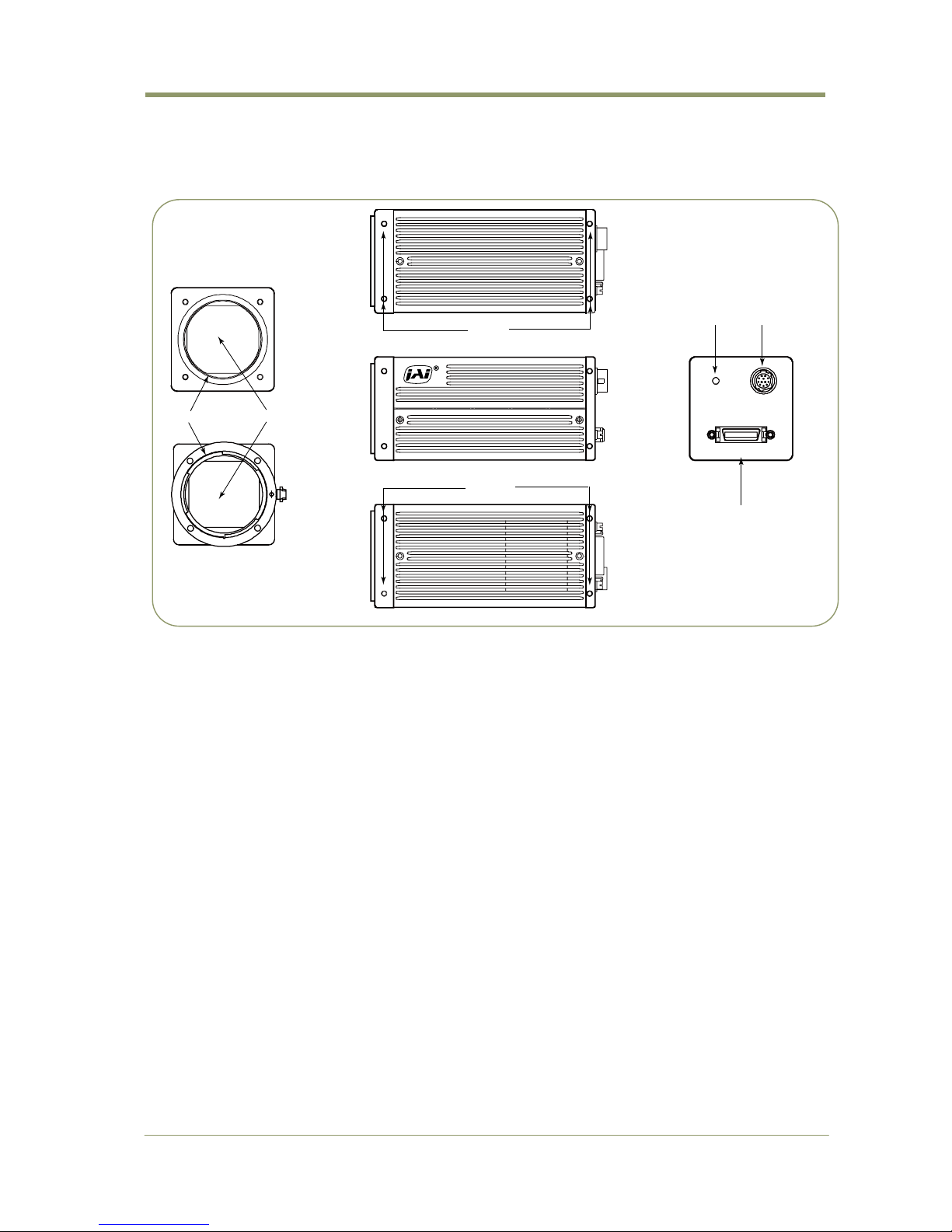
4. Locations and Functions
DIGITAL I/ O
POWER/ TR IG
DC IN / TRIG
DIGITA I/ O
POWER/ TR IG
DC IN / TRIG
①
②
③
④
⑤
⑥
⑥
1 Lens mount Universal P-mount (Note *1)
1 Lens mount Nikon F mount (Note*2)
2 CCD sensor 35mm size CCD sensor
3 26-pin connector Camera Link Interface ( Note *3)
4 12-pin connector DC+12V and trigger input
5 LED Indication for power and trigger input
6 Mounting holes M3 depth 5mm for tripod mount plate (Note *4)
*1) Note: Rear protrusion on Universal P-mount lens must be less than 11.0mm.
*2) Note: Rear protrusion on Nikon F-mount lens must be less than 12.0mm.
*3) Note: When a CameraLink cable is connected to the camera, please do not excessively tighten
screws by using a driver. The CameraLink receptacle on the camera might be damaged.
For security, the strength to tighten screws is less than 0.291 Newton meter (Nm).
Tightening by hand is sufficient in order to achieve this.
*4) Note: The part number for the tripod adapter plate (with 1/4"-20 thread) is MP-41 (option).
Fig. 1. Locations
Page 8

AM-1600CL / AB-1600CL
- 8 -
5. Pin Assignment
5.1. 12-pin Multi-connector (DC-IN/Trigger)
Type: HR10A-10R-12PB-01 (Hirose) male.
Use the part number HR10A-10P-12S for the cable side
*1) Factory default is trigger via Camera Link. 12 pin input can be selected by using serial control.
5.2. Digital Output Connector for Camera Link
Type: 26-pin MDR connector (3M 10226-1A10PL)
Fig.3 26-Pin Camera Link Connector
Pin No In/Out Name Note
1,14 Shield GND
2(-),15(+) O TxOUT0
3(-),16(+) O TxOUT1
4(-),17(+) O TxOUT2
Data out
5(-),18(+) O TxClk Clock for CL
6(-),19(+) O TxOUT3 Data out
7(+),20(-) I SerTC (RxD)
8(-),21(+) O SerTFG (TxD)
LVDS Serial Control
9(-),22(+) I CC1 (Trigger) Trigger IN
10(+),23(-) I CC2(Reserved)
11,24 N.C
12,25 N.C
13,26 Shield GND
Pin no. Signal Remarks
1 GND
2 +12 V DC input
3 GND
4 NC
5 GND
6
NC
7 NC
8 GND
9 XEEN out
10 Trigger in
*1)
11 DC+12V
12 GND
Fig. 2 Hirose 12-pin connector
Page 9

AM-1600CL / AB-1600CL
- 9 -
5.3. Input and output circuits
In the following schematic diagrams the input and output circuits for video and timing signals are
shown.
5.3.1. Trigger input
An external trigger input can be applied
to pin 10 of 12-pin Hirose connector .
The input is AC coupled. To allow long
pulses the input circuit is designed as a
flip flop circuit. The leading and trailing
edges of the trigger pulse activate the
circuit.
The trigger polarity can be changed by
command.
Trigger input level is 4 V ±2 V.
Internal DIP SW700 can terminate the
trigger input by 75 ohm.
Trigger is applied through the Camera
Link connector as the default setting.
Fig.4. Trigger input
5.3.2. XEEN output
XEEN output is on pin 9 on 12-pin Hirose
connector.
The output circuit uses a 75 ohm
complementary emitter follower circuit.
The line voltage is 5V and the output level
is 4V without termination.
XEEN output is always negative polarity.
Through Camera Link connector, EEN
output is available. This output is always
positive polarity.
The polarity for XEEN and EEN cannot be
changed.
Fig.5. XEEN output
5.3.3. Camera Link interface
The digital video is available via Camera Link, with 8-, 10- or 12-bit pixel depth, using the CL Base
configuration. The digital output signals follow the Camera Link standard using Channel Link chip
sets.
The data bits from the digital video, FVAL, LVAL, DVAL and EEN are multiplexed into the twisted
pairs, which are a part of the Camera Link. Trigger signals and the serial camera control are feed
directly through its own pairs.
The 26-pin MDR Camera Link connector pin assignment follows the Camera Link base
configuration.
For a detailed description of the Camera Link standard, please refer to the Camera Link standard
specifications found at the AIA web site, www.machinevisiononline.org.
Page 10

AM-1600CL / AB-1600CL
- 10 -
Port/Signal
8bitOutput 10bitOutput 12bitOutput Pin No.
Port A0 A2 A0 A0 Tx0
Port A1 A3 A1 A1 Tx1
Port A2 A4 A2 A2 Tx2
Port A3 A5 A3 A3 Tx3
Port A4 A6 A4 A4 Tx4
Port A5 A7 A5 A5 Tx6
Port A6 A8 A6 A6 Tx27
Port A7 A9 A7 A7 Tx5
Port B0 B2 A8 A8 Tx7
Port B1 B3 A9 A9 Tx8
Port B2 B4 NC
A10
Tx9
Port B3 B5 NC
A11
Tx12
Port B4 B6 B8 B8 Tx13
Port B5 B7 B9 B9 Tx14
Port B6 B8 NC
B10
Tx10
Port B7 B9 NC
B11
Tx11
Port C0 NC B0 B0 Tx15
Port C1 NC B1 B1 Tx18
Port C2 NC B2 B2 Tx19
Port C3 NC B3 B3 Tx20
Port C4 NC B4 B4 Tx21
Port C5 NC B5 B5 Tx22
Port C6 NC B6 B6 Tx16
Port C7 NC B7 B7 Tx17
LVAL Tx24
FVAL Tx25
DVAL Tx26
EEN Tx23
Output Timing
Tx OUT0
Tx OUT1
Tx OUT2
Tx OUT3
TxCLK
1pixel cycle
A7 A6
EEN C7
C6
B7
B6 A7 A6
C5
LVAL
FVALDVAL
B2 B1
C3
C2
C1
B3
C2
C3
C4
A1 A0
B0
A5
C0
A4
B5
A3
B4
A2
A1 A0
B2
B1
Page 11

AM-1600CL / AB-1600CL
- 11 -
5.4. Video output through Camera Link connector
AM-1600CL and AB-1600CL use a dual tap CCD sensor. The L channel video and R channel video are
recomposed in the camera as one frame of the video. The odd pixel and even pixel on the raster
frame is alternatively output through the camera link connector.
2 channel Pixel Interleaved output.
Page 12

AM-1600CL / AB-1600CL
- 12 -
6. Functions and Operations
6.1. Before starting
6.2. Basic functions
The AM-1600CL / AB-1600CL camera is a progressive scan camera with a16-mega pixel
monochrome or Bayer mosaic color CCD. The interface to the host PC is via digital Camera Link.
Both models output digital video as 8-, 10- or 12-bits. The output through Camera Link connector
is 2 channels, pixel interleaved output. The color version, AB-1600CL, outputs raw Bayer video,
requiring host-based color interpolation. The camera also features several pre-processing
functions (see chapter 6.3)
The camera has a partial scan function selectable as user programmable. It also features
horizontal, vertical and horizontal plus vertical binning modes (AM-1600CL only) for faster frame
rates and increased sensitivity.
There are 2 trigger modes in addition to continuous operation. The Pre-Select and Pulse Width
trigger modes are available with a unique automatic LVAL sync or a-sync selection function.
The functions are described in detail below.
6.2.1. Digital Video Output (Bit Allocation)
The 10-bit digital output is set 890 LSB as 100% video level when CCD output is 200mV.
The white clip level is set at 1023 LSB when CCD output is 230mV.
Digital Out
CCD out
8 bits 10 bits 12 bits
Black 8 LSB 32 LSB 128 LSB
400mV 222 LSB 890 LSB 3560 LSB
460mV 255 LSB 1023 LSB 4095 LSB
0
100
%
Wh i te c l ip Le ve l
Came ra L ink OU T (LSB )
400 460
4095
3560
128
CCDOUT (mV )
Fig.6. Digital Output Bit Allocation ( In case of 12 bits )
Important Note for operation of AM-1600CL and AB-1600CL
AM-1600CL and AB-1600CLcameras use OS (Operating System) inside. Due to this, it is
important to pay special attention when using the camera control tool.
1. The camera cannot communicate with the camera control tool until the LED turns to
GREEN which is approx. 30 seconds.
2. After the camera control tool is initiated, push “Refresh” and then “Connect” for
establishing the communication. Then click the “Refresh Tab” to view the status of
the camera on each window: Gain & Offset, General, Image Processing and Utilities.
It is also necessary to do this for restart.
Page 13

AM-1600CL / AB-1600CL
- 13 -
6.2.2. Electronic Shutter
The AM/AB-1600CL allows the shutter speed to be selected in two ways; preset shutter (10 fixed
steps) and programmable shutter (up to 3248 line periods, 1 LVAL increments).
Preset shutter
0 1 2 3 4 5 6 7 8 9 A
OFF(1/3) 1/6 1/12 1/24 1/48 1/100 1/200 1/400 1/800 1/1600 1/3200
Programmable Shutter
The exposure time can be programmed in 98.66µs (LVAL period) increments. The range is from 3
LVAL to 3248 LVAL. OFF is 3327L. L=LVAL.
Minimum exposure time 3 L Maximum exposure time 3327 L
98.66 µs x 3(L) = 295.98 µs 98.66 µs x 3327 (L) ≈ 328.24 ms
In Binning Mode (Vertical Binning)
Minimum Exposure time Maximum exposure time 1665 L
106.66 µs x 3(L) = 319.98 µs 106.66 µs x 1665(L) = 175.89 ms
6.2.3. Continuous operation or triggered operation
The camera can be operated in continuous mode for applications not requiring asynchronous
external triggering. The camera will operate at its maximum frame rate, 2.99 frames/seconds, in
this mode.
For applications that require an external trigger, the camera can accept external trigger input on
pin 10 of the 12-pin Hirose connector or via the Camera Link interface. This can be selected via
serial interface.
6.2.4. Rear panel indicator.
The rear panel mounted LED provides the following information:
Amber and Red: Power connected – initiating OS
(approx. 20 sec.)
Red: Initiating the application (approx. 10sec.)
Steady green: Camera is operating in Continuous mode
Flashing green: The camera is receiving external trigger
Note: When the camera is receiving the external trigger in
Continuous mode, the LED does not flash.
The LED flashing indicates incoming trigger but not the
trigger duration.
6.2.5. Auto-detect LVAL-sync / async accumulation
This function replaces the manual setting found in older JAI cameras. Whether accumulation is
synchronous or asynchronous in relationship to LVAL depends on the timing of the trigger input.
When trigger is received while FVAL is high (during readout), the camera works in LVALsynchronous mode, preventing reset feed through in the video signal. There is a maximum jitter of
one LVAL period from the start of a trigger to the start of accumulation.
When the trigger is received and FVAL is Low, the camera operates in LVAL-asynchronous mode
(no delay) mode.
This applies to both pre-select (PS) trigger mode and pulse width trigger (PW) mode.
DIGITAL I/ O
POWER / TR IG
DC IN / TR IG
DIGITA I/ O
POWER / TR IG
DC IN / TR IG
Fig.7. Rear Panel indicator
Page 14

AM-1600CL / AB-1600CL
- 14 -
FVAL
(1) (3)
(1) In this period camera executes trigger at next LVAL (prevents feed-through noise)
(2) Avoid trigger at FVAL transition (+/- LVAL period), as the function may randomly
switch between “ next LVAL ” and “ immediate ”.
(2)
External Trigger
+/- 1 LVAL
(3)
In this period, camera executes trigger immediately ( no delay).
Fig.8. Auto-detect LVAL sync/a-sync accumulation
6.2.6. Starting pixel - Bayer color mosaic
The AB-1600CL is a color camera based
on a CCD sensor with a Bayer color
mosaic.
The color image reconstruction is done
in the host PC.
The color sequence in the video signal is
dependent on the scan modes.
AB-1600CL starts with GR sequence for
Full scan mode. In partial scan mode,
the starting line is user programmable
(see next section). When an odd line is
selected for the start, it starts with the
GRG sequence. When an even line is
selected, it starts with BGB sequence.
Fig.9. Bayer layout
6.2.7. Partial Scanning
The partial scanning function employed in AM/AB-1600CL is programmable.
The height of the image can be set from 800 lines as the minimum height and expanded to 3248
lines which is the full scan image. The starting point of the scan can be set from the first line to
2448th line, when the height is set to 800 lines.
The camera has 4 memory settings for use with partial scan mode.
The following describes the programmable partial scan image.
FVAL Timing
LVAL
DVAL
1
57
Full
1
1
16 ck
GBRGG
R G
B
RG R G
Variable
Partial
scan
GBRGG
R G
B
RG R G
Odd
Even
Line # after FVAL raising edge
Actual vertical line #
Page 15

AM-1600CL / AB-1600CL
- 15 -
Variable Partial Scan
Image Height
Image start line
Minimum: 800 lines Maximum: 3248 lines
Image can starts at 1st line
Image can starts at 2448th line
This is in case image height is 800 lines
Fig.10. Variable Partial scan
6.2.8. Binning Functions (AM-1600CL only)
This function is only available on the AM-1600CL camera.
The AM-1600CL incorporates 3 binning modes described below.
Binning mode is a function where the signal charges from 2 adjacent (horizontal or/and vertical)
pixels are added together and read out as one pixel. Binning results in half of horizontal and/or
vertical resolution but higher frame rate and higher sensitivity .
For horizontal binning, a Low Pass Filter (LPF)) is used to realize a smooth edge transition.
The LPF adds the data from the processed pixel and the data from the left and the right pixels of
the processed pixel, using a specified ratio, and replaces the data of the processed pixel with the
added data.
The ratio is fixed and can be selected from the following:
1/4, 1/2, 1/4 :Adding data Ratio Left and right 25%、center 50%
1/8, 3/4, 1/8 :Adding data Ratio Left and right 12.5%、center 75%
Page 16

AM-1600CL / AB-1600CL
- 16 -
4872
3248
Full Area
2436
3248
4872
1624
2436
1624
2,1
1,41,3
1,2
4,44,34,24,1
3,43,33,23,1
2,42,32,2
H 2x V 2x H+V 2x
1,1
1,1 1,2
2,1 2,2 2,1 2,2
1,1 1,1 1,2
2,1 2,2
Add two columns
Add two rows
Add two columns
and two rows
Fig. 11. Binning
6.3. Pre-processing Functions (overview)
AM-1600CL and AB-1600CL have several pre-processing functions.
The pre-processing functions include Blemish Compensation, Flat Field Compensation (pixel nonuniformity) and LUT (Look Up Table). A brief description of each function is included on the
following pages. See Section 8 for instructions regarding how to set up these functions using the
camera’s GUI Control Tool, or see Section 7 for register-level command information.
6.3.1. Blemish Compensation (AM-1600CL only)
AM-1600CL has a blemish compensation circuit. This function compensates for blemishes on the
CCD sensor (typically pixels with extremely high response or extremely low response). This applies
to Monochrome version only. Pixels that fulfill the blemish criteria can be compensated by using
the adjacent pixel on the left side column as shown below.
Page 17

AM-1600CL / AB-1600CL
- 17 -
There is no limit to the number of pixels that can be compensated. As L channel and R channel
images are composed as one image inside the camera, there is also no limitation on L channel and
R channel compensation.
When the leftmost pixel has blemish, it cannot be compensated because there is no data for
compensation.
When two or more consecutive pixels have blemishes, the leftmost pixel with a blemish is
compensated by the left normal pixel data and the second pixel is then compensated by the left
pixel which is already compensated.
The default setting is Disable.
6.3.2. Gain and Channel Balance
The AM-1600CL/AB-1600CL has a dual-tap readout architecture, with Left (L) and Right (R)
channels. In order to achieve the same gain and black level for both channels, the AM-1600CL/AB1600CL has independent control for L channel and R channel gain and offset.
In order to balance both channels, the balancing uses L channel as the reference and R channel is
adjusted so as to have the same level as that of L channel for both gain and offset.
6.3.3. Flat Field Correction (Pixel non-uniformity) (AM-1600CL only)
The flat field correction function can compensate different gain and offset on each pixel. It is
possible to use offset only (black-level correction) or offset and gain corrections in sequence.
6.3.4. Programmable Look-Up Table (LUT) (AM-1600CL only)
AM-1600CL has a programmable look-up table (LUT) that lets the user adjust the gamma
characteristics of the video output by adding “knees” or otherwise adjusting points along the
video response graph.
6.3.5. Test pattern generator
The AM-1600CL and AB-1600CL cameras have the following test pattern generators. While the test
pattern is selected, the video output is disabled. This function does not depend on the setting of
gain and offset. This function can be set by command but the setting is not stored in the memory.
1. Horizontal Ramp
2. Vertical Ramp
3. Horizontal and Vertical Ramp
1 2 3
×
Page 18

AM-1600CL / AB-1600CL
- 18 -
6.4. Sensor Layout and Timing
6.4.1. CCD Sensor Layout
The CCD sensor layout with respect to pixels and lines used in the timing and video full frame read
out is shown below.
Fig. 12. CCD sensor layout
Page 19
AM-1600CL / AB-1600CL
- 19 -
6.4.2. Horizontal Timing
The LVAL period is shown for continuous mode.
LVA L
int_XSUB
int_XSG
(Exposure)
EEN
(CCD out)
DATA out
DVAL
OB
Buffer
Effective pixels
1CLK=33.33 ns ( 30MHz)
Continuous ( LVAL period
)
OB
Buffer
2960
2468 492
88
2436
88
2436
524
Fig. 13. Horizontal Timing
Page 20

AM-1600CL / AB-1600CL
- 20 -
6.4.3. Vertical Timing
The FVAL period for continuous mode full scan is shown.
Continuous mode ( Full frame mode)
FVAL
LVA L
int_XSUB
int_XSG
(Exposure)
EEN
(CCD out)
DATA out
DVAL
3327L
3248L
56L 20L
3L
Buffer
OB
Effective lines
Buffer
OB
40
163248L
16
4
Fig. 14. Vertical Timing for full scan
Page 21

AM-1600CL / AB-1600CL
- 21 -
6.4.4. Partial Scan
Partial scan allows higher frame rates by reading out a smaller portion of the image. This is
particularly useful when inspecting objects that do not fill the whole height of the image.
Vertical timing
FVAL
LVAL
0. 5
L
Fr ont of Fr ame
Back of Fr ame
Effective Lines
1
C
B
A
260
800
20
3
1084
1081
In case the start line:2448 line, image height:800 lines
Partial scan mode (FVAL period)
int High Speed
Transfer
int_XSG
int_XSUB
(Exposure)
EEN
DATA out
DVAL
Fig.15. Partial scan Vertical Timing
Horizontal Timing ( Same as normal scan )
LVA L
int_XSUB
int_XSG
(Exposure)
EEN
(CCD out)
DATA out
DVAL
OB
Buffer
Effective pixels
1CLK=33.33 ns ( 30MHz)
Continuous (LVAL period)
OB
Buffer
2960
2468 492
88
2436
88
2436
524
Fig.16. Partial scan Horizontal Timing
Page 22

AM-1600CL / AB-1600CL
- 22 -
6.4.5. Horizontal and Vertical binning
Vertical binning combines charge from two adjacent rows, while horizontal binning combines
charges from two adjacent columns, reducing the vertical or horizontal resolution to half and at
the same time increasing frame rate. This function is available only for AM-1600CL.
Important Note
Vertical Binning cannot be used together with Partial Scanning.
Vertical Binning (Horizontal Timing)
1 CLK = 33.33ns (30.00MHz)
Binning Continuous ( LVAL Period)
LVA L
int_XSUB
int_XSG
(Exposure)
EEN
(CCD out)
DATA out
DVAL
OB
Buffer
Effective Pixels
OB Buffer
3200
2468
732
88 88
2436
764
2436
Fig.17. Horizontal Timing for Vertical Binning
Page 23

AM-1600CL / AB-1600CL
- 23 -
Vertical Binning (Vertical Timing)
FVAL
LVA L
int_XSUB
int_XSG
(Exposure)
EEN
(CCD out)
DATA out
1665L
1624L
28L 10L 3L
Effective lines
OB
OB
Buffer
Buffer
20L 8L 1624L
8L 2L
Binning Continuous ( Full Frame period)
DVAL
Fig.18. Vertical Timing for vertical binning
6.5. Operation Modes
This camera can operate in 3 primary modes.
1. Continuous Mode. Pre-selected exposure.
2. Edge Pre-select Mode. Pre-selected exposure.
3. Pulse Width Control Mode. Pulse width controlled exposure.
6.5.1. Continuous operation
Applications not requiring asynchronous external triggering should be run in continuous mode.
For timing details, refer to fig. 13 through fig. 18.
Page 24

AM-1600CL / AB-1600CL
- 24 -
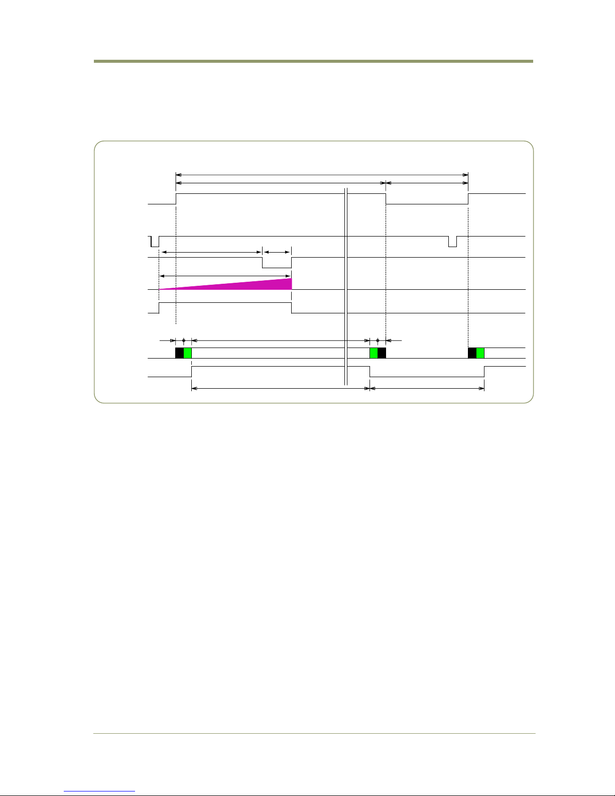
6.5.2. Edge Pre-select Trigger Mode (EPS)
In this mode, an external trigger pulse initiates the capture, and the exposure time (accumulation
time) is defined by the selected shutter time .
The resulting video signal will start to be read out after the shutter time.
For timing details, refer to fig. 13 through fig. 19.
To use this mode:
Set function: Trigger mode EPS
Scanning Normal,
Programmable Partial
H, V or H+V Binning
Shutter mode pre-set or programmable
Shutter speed or
Programmable exposure
Other functions and settings
Input: Ext. trigger Camera Link or 12-pin Hirose
Important notes on using this mode
1. The minimum trigger duration > 1LVAL.
2. Depending on the timing of the leading edge of the trigger pulse in relationship to FVAL,
accumulation will be synchronous or asynchronous in relation to LVAL. See chapter 6.2.5
for details.
3. The minimum interval of the trigger is 3327 LVAL.
Ext . Tr i g.
FVAL
LVAL
EEN
int_XSUB
int_XSG
(Exposure)
( CCD out )
DVAL
DATA out
Ef f ect i ve Li nes
324840 16 16 4
3324L
3L
Edge Pre-select mode (FVAL period)
1L(min.) to 1 Frame(max.)
OB
OB
Fig. 19. Pre-select trigger mode.
Page 25

AM-1600CL / AB-1600CL
- 25 -
6.5.3. Pulse Width Control Trigger Mode (PWC)
In this mode the accumulation time is equal to the trigger pulse width. Here it is possible to have
a long time exposure. For best image quality, the maximum recommended time is <6 frames (2
seconds), however, depending on your application, significantly longer exposure may still produce
an acceptable signal-to-noise ratio, even without applying any external cooling.
For timing details, refer to fig. 13 through fig. 18 and fig. 20.
To use this mode:
Set function: Trigger mode PWC
Scanning Normal
Programmable Partial scan
H, V or H+V binning
Other functions and settings
Input: Ext. trigger Camera Link or 12-pin Hirose
Important notes on using this mode
1. The minimum trigger duration > 2 LVAL and the maximum duration 2 seconds (6 frames)
2. Depending on the timing of the leading edge of the trigger pulse in relationship to FVAL,
accumulation will be synchronous or asynchronous in relationship to LVAL. See chapter
6.2.5 for details.
3. The minimum interval of the trigger is 3331L.
Ext . Tr i g.
FVAL
LVAL
EEN
DVAL
int_XSG
(Exposure)
(CCD out)
DATA ou t
40 16 3248 16 4
3324L
3L
Pulse Width Control mode (FAVL period)
2L(min.) to 6 Frames (max.)
OB
OB
Effective lines
(Data out delay)
Fig. 20. Pulse width trigger mode
Page 26

AM-1600CL / AB-1600CL
- 26 -
6.6. Mode and function matrix
The following table shows which functions will work in the different modes for AM-1600CL / AB1600CL.
Function
Shutter
Binning (Note*1)
Accumulation
Trigger
mode
Pre-set Programmable
Partial
H V H+V
LVAL sync /
async
Cont.
○ ○ ○
○ ○ ○
-
EPS
○ ○ ○
○ ○ ○
Auto
PWC
― ― ○
○ ○ ○
Auto
Note *1) The binning function is available for AM-1600CL only.
Note *2) The partial scan and the Binning functions cannot be used at the same time.
Fig.21. Mode and function matrix.
Page 27

AM-1600CL / AB-1600CL
- 27 -
7. Configuring the Camera
7.1. DIP switch SW700
SW1 provides Enable/Disable 75 ohm termination for the trigger input, which is pin 10 on the
HIROSE connecter.
This switch is located on the inside of the rear panel.
DIPSW
N
O
Function ON OFF
External trigger termination 75 Ω TTL
The factory default is OFF (TTL).
Fig. 22. DIP switch location
7.2. Register based command control
All configuration of the AM-1600CL / AB-1600CL camera is done via serial communication in the
Camera Link connector. The camera can be set up from a PC running terminal emulator software,
or using JAI's camera control software.
The following pages contain a description of the register-based command protocol used in the AM1600CL and AB-1600CL.
Page 28

AM-1600CL / AB-1600CL
- 28 -
Page 29

AM-1600CL / AB-1600CL
- 29 -
Gain & Offset
Min.
Value
Max.
Value
RW Command Note
CH-A 0 0x5FF RW
:R0020@04A0#=00000XXX
Relative Gain adjustment together
with OFF-SET adjustment for L ch.
CH-B 0 0x5FF RW
:R0020@04A4#=00000XXX
Relative Gain adjustment together
with OFF-SET adjustment for R ch
Start Balancing - - WO
:R0020@00E0#=00000001
Adjust R ch Gain to be equal with
that of L ch
Stop Balancing - - WO
:R0020@00E0#=00000000
Stop balancing operation
Done Status - - RW
:R0020@00E4?
After the balancing is completed, change
from "00000000" to "00000001".
Stop Status - - RW
:R0020@00E8?
When the stop is accepted, change
from "00000000" to "00000001".
Factory/User
Selection
--RW
:R0010@02E4#=00000XXX
0: Factory , 1: User
Factory Gain Index 0 255 RW
:R0010@02E8#=00000XXX
Default is 0
User Gain Index 0 255 RW
:R0010@02EC#=00000XXX
Default is 0
Execute - - WO
:R0020@0460#=00000001
Write "00000001" , then the save is
executed.
Factory/User
Selection
--RW
:R0020@0464#=0000000X
0: Factory , 1: User
Index Number 0 255 RW
:R0020@0468#=000000XX
Default is 0
dB Value -3,000,000 +1,300,000 RW
:R0020@046C#=00000004
1,000,000 times by DB value.
Example: 3dB is 3,000,000.
Start Balancing - - WO
:R0020@03C0#=00000001
At first, set the L channel OFF-SET
at the expected value. Then set the
R channel OFF-SET at the average
value of L channel.
Stop Balancing - - WO
:R0020@03C0#=00000000
Stop balancing operation
Done Status - - RO
:R0020@03C4?
After the balancing is completed, change
from "00000000" to "00000001".
Stop Status - - RO
:R0020@03C8?
When the stop is accepted, change
from "00000000" to "00000001".
Factory/User
Selection
--RW
:R0010@0314#=0000000X
0: Factory, 1: User
Factory Gain Index 0 255 RW
:R0010@0318#=000000XX
Default is 0
User Gain Index 0 255 RW
:R0010@031C#=000000XX
Default is 0
Execute - - RW
:R0020@0490#=00000001
Write "00000001" , then the save is
executed.
Factory/User
Selection
--RW
:R0020@0494#=0000000X
0: Factory, 1: User
Index Number 0 255 RW
:R0020@0498#=000000XX
Default is 0
Black Offset Level -100 +300 RW
:R0020@049C#=XXXXXXXX
Minimum and maximum values depend
on the difference occurred in the circuits
through AFE circuit. Register value is
the tow's complement.
Offset
0dB Gain
Offset Balance
Load from
RAM Table
Functions
Gain
Relative Gain
with
Offset Adjustment
Channel Balance
Load from
RAM Table
Save to
RAM Table
Save to
RAM Table
Page 30

AM-1600CL / AB-1600CL
- 30 -
Exposure
Min.
Value
Max.
Value
RW Command Note
Common
Control Mode
Selection
--RW
:R0010@0080#=0000000X
Select Exposure control mode.
0: Preset mode control、1: Line step
mode
Preset Mode
Table Type
--RW
:R0010@0084#=0000000X
Select Factory or User table
on Preset mode
Max Selection for
Preset Factory
00xFRW
:R0010@0088#=0000000X
Maximum index( size) of Factory table
on Preset mode
Current Selection
for Preset Factory
00xFRW
:R0010@008C#=0000000X
The current using index of Factory
table on Preset mode
Max Selection
for Preset User
00xFRW
:R0010@0090#=0000000X
Maximum index( size) of User table
on Preset mode
Current Selection
for Preset User
00xFRW
:R0010@0094#=0000000X
The current using index of User table
on Preset mode
Direct Mode
Table Type
--RW
:R0010@0098#=0000000X
Select Factory or User table on
Line Step mode
Min Direct
Exposure
33248RW
:R0010@009C#=00000XXX
Minimum step number of Factory set
on Line Step control
Max Direct
Exposure Time
Factory
33248RW
:R0010@00A0#=00000XXX
Maximum step number of Factory set
on Line Step control
Current Direct
Exposure Time
Factory
33248RW
:R0010@00A4#=00000XXX
Current step number of Factory set
on Line Step control
Min Direct
Exposure
Time User
33248RW
:R0010@00A8#=00000XXX
Minimum step number of User set
on Line Step control
Max Direct
Exposure
Time User
33248RW
:R0010@00AC#=00000XXX
Maximum step number of User set
on Line Step control
Direct Exposure
Time User
33248RW
:R0010@00B0#=00000XXX
Current step number of User set
on Line Step control
Functions
Exposure
Preset Mode
Line Step Mode
LUT
Min.
Value
Max.
Value
RW Command Note
--RW
:R0010@00C0#=00000000
--RW
:R0010@00C0#=00000001
--RW
:R0010@00C0#=00000002
--RW
:R0010@00C0#=00000003
--RW
:R0010@00C0#=00000004
--RW
:R0010@00C0#=00000005
--RW
:R0010@00C0#=00000006
--RW
:R0010@00C0#=00000007
--RW
:R0020@0130#=0000000X
0: Linear , 1: 0.45,
2 to 7 : User 1 to User 6
Load - - WO
:R0020@0134#=00000001
Write "00000001" to execute " Load ".
Save - - WO
:R0020@0138#=00000001
Write "00000001" to execute " SAVE ".
Point 0 0 0 RW
:R0020@0140#=00000000
X coordinate position of LUT first point.
MUST be 0.
Point 1 0 65535 RW
:R0020@0144#=0000XXXX
X coordinate position of LUT 2nd point.
Point 2 0 65535 RW
:R0020@0148#=0000XXXX
X coordinate position of LUT 3rd point.
Point 3 0 65535 RW
:R0020@014C#=0000XXXX
X coordinate position of LUT 4ht point.
Point 4 0 65535 RW
:R0020@0150#=0000XXXX
X coordinate position of LUT 5th point.
Point 5 0 65535 RW
:R0020@0154#=0000XXXX
X coordinate position of LUT 6th point.
Point 6 0 65535 RW
:R0020@0158#=0000XXXX
X coordinate position of LUT 7th point.
Point 7 0 65535 RW
:R0020@015C#=0000XXXX
X coordinate position of LUT 8th point.
Point 8 0 65535 RW
:R0020@0160#=0000XXXX
X coordinate position of LUT 9th point.
Point 9 0 65535 RW
:R0020@0164#=0000XXXX
X coordinate position of LUT 10th point.
Point 10 0 65535 RW
:R0020@0168#=0000XXXX
X coordinate position of LUT 11th point.
Point 11 0 65535 RW
:R0020@016C#=0000XXXX
X coordinate position of LUT 12th point.
Point 12 0 65535 RW
:R0020@0170#=0000XXXX
X coordinate position of LUT 13th point.
Point 13 0 65535 RW
:R0020@0174#=0000XXXX
X coordinate position of LUT 14th point.
Point 14 0 65535 RW
:R0020@0178#=0000XXXX
X coordinate position of LUT 15th point.
Point 15 0 65535 RW
:R0020@017C#=0000XXXX
X coordinate position of LUT 16th point.
Point 16 0 65535 RW
:R0020@0180#=0000XXXX
X coordinate of 17th point. This is
the virtual point to get the last slope.
User 5
User 6
Select Table
Request Job
User Table
Generation
Functions
Table Selection
Linear
Pivot
The curve data can only be changed
on Factory
Gamma
User 1
The curve data can be changed on
User and the tool is supplied.
User 2
User 3
User 4
Page 31

AM-1600CL / AB-1600CL
- 31 -
LUT(continued)
Point 0 0 131071 RW
:R0020@0190#=000XXXXX
Y coordinate position of LUT first point.
MUST be 0.
Point 1 0 131071 RW
:R0020@0194#=000XXXXX
Y coordinate position of LUT 2nd point.
Point 2 0 131071 RW
:R0020@0198#=000XXXXX
Y coordinate position of LUT 3rd point.
Point 3 0 131071 RW
:R0020@019C#=000XXXXX
Y coordinate position of LUT 4th point.
Point 4 0 131071 RW
:R0020@01A0#=000XXXXX
Y coordinate position of LUT 5th point.
Point 5 0 131071 RW
:R0020@01A4#=000XXXXX
Y coordinate position of LUT 6th point.
Point 6 0 131071 RW
:R0020@01A8#=000XXXXX
Y coordinate position of LUT 7th point.
Point 7 0 131071 RW
:R0020@01AC#=000XXXXX
Y coordinate position of LUT 8th point.
Point 8 0 131071 RW
:R0020@01B0#=000XXXXX
Y coordinate position of LUT 9th point.
Point 9 0 131071 RW
:R0020@01B4#=000XXXXX
Y coordinate position of LUT 10th point.
Point 10 0 131071 RW
:R0020@01B8#=000XXXXX
Y coordinate position of LUT 11th point.
Point 11 0 131071 RW
:R0020@01BC#=000XXXXX
Y coordinate position of LUT 12th point.
Point 12 0 131071 RW
:R0020@01C0#=000XXXXX
Y coordinate position of LUT 13th point.
Point 13 0 131071 RW
:R0020@01C4#=000XXXXX
Y coordinate position of LUT 14th point.
Point 14 0 131071 RW
:R0020@01C8#=000XXXXX
Y coordinate position of LUT 15th point.
Point 15 0 131071 RW
:R0020@01CC#=000XXXXX
Y coordinate position of LUT 16th point.
Point 16 0 131071 RW
:R0020@01D0#=000XXXXX
Y coordinate of 17th point. This is
the virtual point to get the last slope.
Point 0 0x80 0x7F RO
:R0020@01E0#?
The slope of LUT first point.
Calculated by 1st and 2nd points.
Point 1 0x80 0x7F RO
:R0020@01E4#?
The slope of LUT 2nd point.
Calculated by 2nd and 3rd points.
Point 2 0x80 0x7F RO
:R0020@01E8#?
The slope of LUT 3rd point.
Calculated by 3rd and 4th points.
Point 3 0x80 0x7F RO
:R0020@01EC#?
The slope of LUT 4th point.
Calculated by 4th and 5th points.
Point 4 0x80 0x7F RO
:R0020@01F0#?
The slope of LUT 5th point.
Calculated by 5th and 6th points.
Point 5 0x80 0x7F RO
:R0020@01F4#?
The slope of LUT 6th point.
Calculated by 6th and 7th points.
Point 6 0x80 0x7F RO
:R0020@01F8#?
The slope of LUT 7th point.
Calculated by 7th and 8th points.
Point 7 0x80 0x7F RO
:R0020@01FC#?
The slope of LUT 8th point.
Calculated by 8th and 9th points.
Point 8 0x80 0x7F RO
:R0020@0200#?
The slope of LUT 9th point.
Calculated by 9th and 10th points.
Point 9 0x80 0x7F RO
:R0020@0204#?
The slope of LUT 10th point.
Calculated by 10th and 11th points.
Point 10 0x80 0x7F RO
:R0020@0208#?
The slope of LUT 11th point.
Calculated by 11th and 12th points.
Point 11 0x80 0x7F RO
:R0020@020C#?
The slope of LUT 12th point.
Calculated by 12th and 13th points.
Point 12 0x80 0x7F RO
:R0020@0210#?
The slope of LUT 13th point.
Calculated by 13th and 14th points.
Point 13 0x80 0x7F RO
:R0020@0214#?
The slope of LUT 14th point.
Calculated by 14th and 15th points.
Point 14 0x80 0x7F RO
:R0020@0218#?
The slope of LUT 15th point.
Calculated by 15th and 16th points.
Point 15 0x80 0x7F RO
:R0020@021C#?
The slope of LUT 16th point.
Calculated by 16th and 17th points.
Table Selection - - WO
:R0020@0030#=0000000X
0: Linear , 1: 0.45,
2 to 7 : User 1 to User 6
Read Status - - RO
:R0020@0034#?
Bit X corresponds P oint X.
In c a se B it X is 1 , e rro r (w ro n g )
User Table
Generation
Offset
Slope
Slope Value
Page 32

AM-1600CL / AB-1600CL
- 32 -
Miscellaneous
Min.
Value
Max.
Value
RW Command Note
Free-run - - RW
:R0010@0014#=00000000
Synchronize with the Internal Pulse Rest
( Free Run Mode )
Trigger-Run - - RW
:R0010@0014#=00000001
Synchronized with the External Trigger
Pulse ( Trigger Mode)
Trigger Mode EPS - - RW
:R0010@0024#=00000000
Trigger mode. The pre-set exposure
PWC - - RW
:R0010@0024#=00000001
Trigger mode. The pulse width exposure
LOW - - RW
:R0010@0344#=00000000
Negative polarity
HIGH - - RW
:R0010@0344#=00000001
positive polarity
LOW - - RW
:R0010@0340#=00000000
Negative polarity
HIGH - - RW
:R0010@0340#=00000001
positive polarity
HIROSE 12 pin - - RW
:R0010@0380#=00000001
Trigger input select for 12 pin
Camera link - -
:R0010@0380#=00000000
Trigger input select for Camera Link,
Auto Sync
/Async Detect
Enable/Disable - - RW
:R0010@0028#=0000000X
0: Disable, 1: Enable、 Default is 1: Enable
Enable - - RW
:R0010@0118#=00000001
Partial scan is enabled
Disable - - RW
:R0010@0118#=00000000
Partial scan disabled
07RW
:R0010@0114#=0000000X
Select one area out of 8 areas
Start 0 3247 RW
:R0010@0120#=00000XXX
Start line of Partial scan
Height 800 3247 RW
:R0010@0124#=00000XXX
Line numbers for Partial scan
( Height of the picture)
Start 0 3247 RW
:R0010@0128#=00000XXX
Start line of Partial scan
Height 800 3247 RW
:R0010@012C#=00000XXX
Line numbers for Partial scan
( Height of the picture)
Start 0 3247 RW
:R0010@0130#=00000XXX
Start line of Partial scan
Height 800 3247 RW
:R0010@0134#=00000XXX
Line numbers for Partial scan
( Height of the picture)
Start 0 3247 RW
:R0010@0138#=00000XXX
Start line of Partial scan
Height 800 3247 RW
:R0010@013C#=00000XXX
Line numbers for Partial scan
( Height of the picture)
None - - RW
:R0010@0104#=00000000
Vertical Binning function is OFF
2X - - RW
:R0010@0104#=00000001
Two Rows binning for vertical direction
--RW
:R0010@0170#=0000000X
0: Both Horizontal Binning and LPF
are disable
1: Horizontal Binning is enable
2: LPF is enable
2X - - RW
:R0010@0174#=00000000
Two columns Binning for Horizontal
direction
1/4 1/2 1/4 - - RW
:R0010@0178#=00000000
Among three pixels for horizontal
direction, add each 25% of the first
and the last pixel data and 50% of
the center pixel data to make the
center pixel data
1/8 3/4 1/8 - - RW
:R0010@0178#=00000001
Among three pixels for horizontal
direction, add each 12.5% of the first
and the last pixel data and 75% of the
center pixel data to make the center
pixel data
8bit - - RW
:R0010@00E0#=00000000
8 bit depth ( 256 )
10bit - - RW
:R0010@00E0#=00000001
10 bit depth ( 1024 )
12bit - - RW
:R0010@00E0#=00000002
12 bit depth ( 4096 )
TTLIN1 Polarity - - RW
:R0010@0340#=0000000X
0 : Active Low, 1 : Active High
TTLIN1 Software Control - - RW
:R0010@0360#=0000000X
0 : Hardware Control IO
1 : Software Control IO
Pixel Depth
External I/O
V-Binning
Horizontal
Effects
H-Binning/LPF Selection
LPF
Partial Scan
Enable/Disable
Area Selection
Area A
Control Mode
Camera Link
trigger polarity
Area B
Area C
Area D
HIROSE 12-pin
trigger polarity
Functions
Trigger Select
V-Reset
Page 33

AM-1600CL / AB-1600CL
- 33 -
Parameter
Min.
Value
Max.
Value
RW Command Note
--RW
:R0010@0000#=0000000X
0 : Page 0, 1 : Page 1
Execute - - RW
:R0020@0040#=00000001
Write "00000001" to execute " SAVE "
Page Select - - RW
:R0020@0044#=0000000X
0 : Page 0, 1 : Page 1
Execute - - RW
:R0020@0048#=00000001
Write "00000001" to execute " LOAD "
Page Select - - RW
:R0020@004C#=0000000X
0 : Page 0, 1 : Page 1
Execute - - RW
:R0020@0050#=00000001
Write "00000001" to execute verification
Page Select - - RW
:R0020@0054#=0000000X
0 : Page 0, 1 : Page 1
Read Result - - RO
:R0020@0058#?
Number of error detection
(Data Mismatching of Flash memory
and RAM )
Functions
Parameter
Storage
(Page Memory)
Initial Loaded Page
Save
Load
Verification
Trouble Shooting
Min.
Value
Max.
Value
RW Command Note
Execute - - WO
:R0020@0000#=00000001
The same initialization as Cold Start
except FPGA reset
Hardware Status - - RO
:R0020@0010#?
Bit 0 : :GPIO, Bit 1 : AFE, Bit 2 : TSG,
Bit 3 : DAC, Bit 4 : Flash Memory、
Bit 5 : WDT
0x800 0x7FF RO
:R0020@0060#?
Inside temperature around CCD
( -128ºC to + 128ºC )
--RW
:R0020@0230#=0000000X
Test pattern output
0 : No output, 1 : Horizontal Ramp、
2 : Vertical Ramp、3 : H/V Mix Ramp
Functions
Reset
CCD Temperature
Test Pattern
Revision and Camera Information
Min.
Value
Max.
Value
RW Command Note
Firmware 0 - - RO
:R0000@A6D4#?
Revision number of Camera Control
Firmware
Firmware 1 - - RO
:R0000@A6D8#?
Revision number of OS
FPGA 0 - - RO
:R0000@A6F4#?
Revision number of FPGA
BASESET - - RO
:R0020@0110#?
Date and revision of Factory setting
script (BASESET)
Model - - RO
:R0000@0068$?
Model name
Device Version - - RO
:R0000@0088$?
Revision number of camera
Manufacturer Name - - RO
:R0000@0048$?
Manufacture's name
Manufacturer
Specific Info
--RO
:R0000@00A8$?
Manufacture's specific information
Serial Number - - RO
:R0000@00D8$?
Camera serial number
Camera ID - - RO
:R0000@00E8$?
Load camera ID
Functions
Revision
Camera Information
Page 34

AM-1600CL / AB-1600CL
- 34 -
Image Processing
Min.
Value
Max.
Value
RW Command Note
None - - RW
:R0010@02AC#=00000000
No use of any functions
Offset Correction - - RW
:R0010@02AC#=00000001
Use only OFFSET correction
Gain and Offset
Correction
--RW
:R0010@02AC#=00000002
Use Gain and OFFSET correction
Image Subtraction - - RW
:R0010@02AC#=00000003
Sunstract image
Run/Stop - - WO
:R0020@02A0#=0000000X
1 : Start 0 : Stop
Status - - RO
:R0020@02A4#?
Bit 0 : Complete Bit 1 : Stop
Progress 0 100 RO
:R0020@02B0#?
Completion ratio until now ( % )
Run/Stop - - WO
:R0020@02A8#=0000000X
1 : Start 0 : Stop
Status - - RO
:R0020@02AC#?
Bit 0 : Complete Bit 1 : Stop
Progress 0 100 RO
:R0020@02B4#?
Completion ratio until now ( % )
11bit - - RW
:R0010@02A4#=00000000
Gain compensation data in 11 bits
12bit - - RW
:R0010@02A4#=00000001
Gain compensation data in 12 bits
04095
216
0511
04095
Enable - - RW
:R0010@02B8#=00000000
Compensation is effective
Disable - - RW
:R0010@02B8#=00000001
Compensation is not effective
Dark RO
:R0020@02D8#?
Detected black defective pixel numbers
Bright RO
:R0020@02DC#?
Detected white defective pixel numbers
Run/Stop - - WO
:R0020@02C0#=0000000X
1 : Start 0 : Stop
Status - - RO
:R0020@02C4#?
Bit 0 : Complete Bit 1 : Stop
Dark Ratio 0 100 RW
:R0010@02B0#?
0% ( 0 ) to 100% ( 100 )
Progress 0 100 RO
:R0020@02D0#?
Completion ratio until now ( % )
Run/Stop - - WO
:R0020@02C8#=0000000X
1 : Start 0 : Stop
Status - - RO
:R0020@02CC#?
Bit 0 : Complete Bit 1 : Stop
Data Level 0 65535 RW
:R0010@02B4#?
16 bit LSB
Progress 0 100 RO
:R0020@02D4#?
Completion ratio until now ( % )
Control - - WO
:R0020@0270#=0000000X
1 : Execute " SAVE "
0 : Interrupt " SAVE "
Done - - RO
:R0020@0274#?
Complete by "00000001"
Control - - WO
:R0020@027C#=0000000X
1 : Execute " LOAD "
0 : Interrupt " LOAD "
Done - - RO
:R0020@0280#?
Complete by "00000001"
Control - - RW
:R0020@0288#=0000000X
1 : Execute " VERIFICATION "
0 : Interru
p
t " VERIFICATION "
Done - - RW
:R0020@028C#?
Complete by "00000001"
Error Count 0 ? RO
:R0020@0298#?
Number of error detection
(Data Mismatching of Flash memory
and RAM )
0100RO
:R0020@029C#?
Completion ratio until now ( % )
Coef Save
Coef Load
Coef Verification
Progress
Blemish
Compensation
Enable/Disable
Count
Blemish
Compensation
Calibration
Dark
Bright
Loop
Black Average
Bright Coef
Flat Field
Compensation
Function Used
Flat Field
Compensation
Calibration
Dark Calibration
Coef Bit
K.Value
Bright Calibration
Functions
Compensation
Common
NOTE: Do not try to use commands not shown in this list.
Page 35

8. Camera Control Tool for AM-1600CL / AB-1600CL
8.1. General
The Camera Control Tool for Windows 2000/XP/Vista can be downloaded from www.jai.com.
The AM-1600CL/AB-1600CL Camera Control Tool has the following windows:
Configuration, Camera Settings, About, Gain & Offset, General, Image Processing and Utilities.
The Gain & Offset, General, Image Processing, and Utilities windows also contain a
Communication window.
The camera control software is for configuring and setting parameters of the AM-1600CL and AB1600CL. The interface is asynchronous serial communication through Camera Link, SerTFG and
SerTC. The data can be stored in the EEPROM of the cameras.
8.2. How to install
The software is in a compressed file and in order to install it, you must first extract the file.
After extraction, SETUP.exe is created.
The following is the setup procedure.
1. Click SETUP.exe
2. Follow the SETUP screen, Click[ NEXT]
3. Select a default location or input your own path. Then, click [NEXT].
Page 36

AM-1600CL / AB-1600CL
- 36 -
4. Start to install the software
5. When the installation is completed. Click [CLOSE].
8.3. Start up the software
In order to communicate with the camera , it is necessary to select the appropriate port after
starting up the software.
1. Click the Camera control tool icon to start up the software.
Page 37

AM-1600CL / AB-1600CL
- 37 -
2. The following start-up screen appears.
Note: At this moment, communication is not initiated.
8.4. How to connect the camera
1. Click [Refresh] to read available ports.
Page 38

AM-1600CL / AB-1600CL
- 38 -
2. Select the appropriate port ( in this case , COM3)
Note: The available ports will differ depending on the setting of the Frame Graber board.
Check the COM setting of Frame Graber board.
3. Click [Connect] in order to connect the camera.
4. After the connection is activated, the indication is changed to [Disconnect].
8.5. How to disconnect the camera
Click [Disconnect] and when the indication is changed to [Connect] , the camera is
disconnected.
8.6. How to reconnect the camera
While the camera is connecting to the control tool software, if the camera power is OFF,
click [Disconnect] and follow the procedure described in “8.4 How to connect the camera”.
8.7. Description of screens and functions
8.7.1 Initial screen and inclusion of camera setting status
After connecting the camera, the control tool indicates the following status.
In order to read the camera setting status, click [Refresh tab].
Page 39

AM-1600CL / AB-1600CL
- 39 -
Note: [Refresh Tab] is independent on each control page. Accordingly, clicking on [Refresh
tab] should be executed on each screen such as “General”, “Image Processing” and
“Utilities”.
Once it is executed, the communication between the control tool and camera is
activated, and the indication of the control tool and the camera settings are
synchronized.
Page 40

AM-1600CL / AB-1600CL
- 40 -
8.7.2 Functions
8.7.2(a) Gain & Offset
Use these control to balance the left and right channels of the dual-tap output. Options
are provided for manual or automatic balancing.
n Offset : This is used to adjust the video black level of the right channel to match the
left channel. It should be performed by covering the lens, then adding or subtracting an
offset value by clicking on the up or down buttons, or by entering the value directly in
the text box.
Page 41

AM-1600CL / AB-1600CL
- 41 -
■ Offset value can be changed from -512 to +511 for 12 bit output.
■ When Gain 0 Level Balance is set to ON, automatic R/L black balance is initiated.
o Gain : Use these control to adjust video gain and R/L gain balance. This is best
achieved by first exposing the camera to a uniform light source under 80% saturation.
◆ Manual adjustment for Gain and Gain channel balance
Input the appropriate value between -3dB and +12dB in A(dB) and B(dB) to adjust the
gain and gain channel balance for L and R channels. Use the up and down arrows, or
type the values directly into the text boxes.
◆ Automatic gain and gain channel balance
1. Click [ON] in the Balance pane.
2. Input the required gain value in [A(dB)] , for instance 3.
3. Click the balance [ON]. After completion, ON turns OFF automatically.
Note: The Automatic balance adjustment for AM-1600CL and AB-1600CL uses L channel
(A) as the reference level and adjusts R channel (B) so that it matches to the L
channel level.
p RAM table: Use this control to store the settings for Gain and Offset in Flash memory
or to load from Flash memory into RAM. There are four user memories available for
storing Offset and Gain settings.
Note: There are Factory memories but these are only for loading factory data
to camera.
◆How to select the table
Page 42

AM-1600CL / AB-1600CL
- 42 -
[Offset Load] and [Gain Load] can load the Factory data or the user data independently.
Four user indexes (0 to 3 )are available for each Offset and Gain.
Use [Load Master Index] to select the same index for both Gain and Offset.
◆How to store Offset and Gain data
1. Select the location by Index ( 0 to 3)
2. Click [Save] for saving data for Offset and Gain
3. Click [Save RAM to Flash]
Note: Data cannot be stored if the power of the camera is OFF before the execution of
[Save RAM to Flash].
Special Caution: For saving data, Factory settings should not be used. Doing so will
cause Factory default-data to be over-written.
After the setting data is stored in flash memory, when the camera is restarted, the saved
data can be loaded to the camera as the initial settings.
◆How to load to the RAM Table
Select the table (Factory or User) and Index ( 0 to 3) and read the required Offset and
Gain setting data.
Page 43

AM-1600CL / AB-1600CL
- 43 -
8.7.2(b) General
Note: In order to store the setting data on this page, click [Save RAM to Flash] on Gain &
Offset page. The characteristics for LUT data can be stored on LUT setting page.
n Exposure: Set exposure time.
Use this to control the camera’s electronic shutter settings.
■No Shutter: No shutter operation
■Preset : Select Preset shutter speed. 0 to A(see the table below)
■Direct : Set the exposure from 3L to 3248L by 1 LVAL increments. Use the
buttons or type the value directly into the text box.
Setting Shutter
Speed
Setting Shutter
Speed
0 1/3(OFF) 6 1/200
1 1/6 7 1/400
2 1/12 8 1/800
3 1/24 9 1/1600
4 1/48 A 1/3200
5 1/100
Page 44

AM-1600CL / AB-1600CL
- 44 -
o V-Reset
Use this area to indicate whether or not the camera will be controlled by triggering.
Free-run : Continuous operation by internal trigger
Trigger-Run : Indicates that an external trigger will be used.
Select EPS or PWC for Trigger-Run mode
p Trigger Control
Select whether the trigger input will come via the HIROSE 12-pin or the Camera Link
connector. Also select the trigger polarity for Camera Link and 12-pin respectively.
q Pixel Depth
Select the depth of the video output through Camera Link. Choose from 12 bits, 10 bits
or 8 bits.
r Frames to Capture
Select the number of frames to capture per trigger: from 1 to 4 frames
s Gamma (AM-1600CL only)
Select the type of video output response from the following choices (this function is only
for AM-1600CL).
■Linear (γ=1.0)
■Gamma (γ=0.45)
■USER 1 to 6: User programmable LUT (refer to LUT instructions below)
Page 45

AM-1600CL / AB-1600CL
- 45 -
LUT (AM-1600CL only)
When a Gamma type of USER 1 to USER 6 is selected, a user-programmable Look-Up
Table (LUT) appears. By using the LUT, the desired video output characteristics for the
system can be created and stored.
◆How to use the LUT
1 Select one of the user-programmable options (User 1 to 6 in the Table drop-down)
Click [Load Selected] to load any previously saved values for this setting.
Note: As for [Linear] and [Gamma], the characteristics can not be changed.
2 Click [Linearize Graph] to produce a line with adjustable points representing the
video response to specific light levels.
3 Select a point from the graph. The range within which the response can be adjusted
is shown in green.
Point
Page 46

AM-1600CL / AB-1600CL
- 46 -
4 Drag the point to a new location within the range or enter new coordinates in the X
and Y boxes. Repeat with additional points until the desired response is defined.
Example
↓
5 Click [Save Graph] to save this setting for future recall.
u Horizontal-Binning & LPF (AM-1600CL only)
Use this area to activate the horizontal binning function and LPF(Low Pass Filter).
■None : No horizontal binning
■Binning : Add two pixels in horizontal direction and read as one pixel
■LPF : Add the data from the processed pixel and the data from the left and the
right pixels of the processed pixel by a certain ratio and replace the data of
the processed pixel with added data.
The ratio is fixed and can be selected from the followings.
1/4, 1/2, 1/4 :Adding data ratio left and right 25%、center 50%
1/8, 3/4, 1/8 :Adding data ratio left and right 12.5%、center 75%
Vertical-Binning (AM-1600CL only)
Use this area to activate the vertical binning function
■None:No vertical binning (Normal)
■2x :Add pixels in two rows (vertical direction)
Note: It is possible to activate both horizontal binning and vertical binning simultaneously.
Optical Black Video out
Disable:No optical black is output
Enable: Optical black is output
Page 47

AM-1600CL / AB-1600CL
- 47 -
11
Partial Scan
Select [Enable] to initiate partial scanning, then enter the start line and the image height.
Four settings (A to D) can be stored for future use.
8.7.2(C) Image Processing
Note: In order to save the status of settings on this page, click [Save RAM to Flash] on the
Gain & Offset page.
n Blemish (AM-1600CL only)
You can choose to activate blemish compensation or you can leave it off, which is the
factory default setting. Blemish compensation will compensate both dark and bright
pixels.
■ Blemish:Use this area to activate the blemish compensation function ( Enable /
Disable)
Important note: At the first start up, the camera loads data from the initial
calibration which has been performed at the factory.
Page 48

AM-1600CL / AB-1600CL
- 48 -
o Blemish Compensation Calibration (AM-1600CL only)
Initial blemish compensation calibration is performed at the factory and is not typically
required. Factory data is loaded at startup and is then applied if the user has enabled
Blemish Compensation. If subsequent calibration is performed, it must be done in the
sequence of [Dark] first, then [Bright].
To perform calibration, first click [Run] in the [Dark] section. You will be instructed to
set a particular saturation level for compensation. The process will then proceed
automatically until the compensation data for dark pixels has been created. Use the
[STOP] button if you want to halt the process before it is completed.
Repeat the process in the [Bright] section to read in compensation data for the bright
pixels.
Both [Dark] and [Bright] calibration must be performed as a set. [Dark] only or [Bright]
only cannot be initiated.
Use the remaining controls as follows:
Save:Save the compensation data stored in RAM to Flash memory
Load: Load the [Dark] and [Bright] compensation data
Verify:Verify the data in RAM and in Flash memory to be the same
Special Caution: When saving calibration data, Factory default settings are over-
written. Special attention is needed.
p Flat Field Compensation (AM-1600CL only)
Flat field compensation uses per-pixel gain and/or offset correction to adjust the image
for non-uniform sensor response. Use the Mode drop-down list to enable flat field
compensation by choosing the type of correction you wish to perform. Choices are:
■ None :No flat field compensation
■ Offset Correction :Correct the black level shading only
■ Gain and Offset Correction:Correct both black level and gain level
■ Image Subtraction :Identify the adjustment by comparing to the previous
frame (adjust-areas which are different in video level
from the previous frame)
After selecting a flat field compensation mode -Offset, Offset & Gain or Image
Subtraction- you must execute [Flat Field Compensation Calibration] before the
compensation can be performed.
Page 49

AM-1600CL / AB-1600CL
- 49 -
Calibration must be performed in the sequence of [Dark] first, then [Bright]. Begin by
clicking the [RUN] button in the [Dark] section. A pop-up window will instruct you to
close the lens before continuing. Calibration will then proceed automatically untill
completed. The status window next to the [STOP] button shows the percentage of
completion. It can take up to 20 minutes for a calibration to be performed. Click the
[Stop] button to halt the calibration at any time.
When [Dark] calibration is completed, click the [RUN] button in the [Bright] section. You
will be prompted to open the lens to a saturation level of approximately 50% before
continuing. Calibration will then proceed automatically unless halted by clicking the
[STOP] button.
Both [Dark] and [Bright] calibration must be performed as a set. [Dark] only or [Bright]
only cannot be initiated.
After running both [Dark] and [Bright] calibration, the data should be saved to Flash
memory to avoid having to rerun calibration. Click [Start] button in the [Save] section to
save the data. The process can take up to 40 minuates.
If a flat field compensation mode has been selcted and saved via the [Save RAM to Flash]
command on the Gain & Offset page, the calibration settings will be automatically loaded
to the Camera at start-up (the rear panel indicator light will turn red during the loading
process, which may last a few minutes).
Use the [Load] section to load pre-saved calibration data from Flash to RAM.
Use the [verify] section to compare new calibration data in RAM to saved data in Flash
memory.
8.7.2(d) Utilities
On this screen, model name, firmware versions and test patterns are indicated.
Page 50

AM-1600CL / AB-1600CL
- 50 -
■ Test Pattern:The following three patterns are available.
H.ramp V.ramp H & V ramp
■ Flash memory: There is a flash memory of two pages for saving data. The saved data
can be loaded to the camera or verified.
8.8. Other menu selection
The camera controller software has two additional drop-down menus located in the top
bar of the software.
Configuration Menu
Reply Wait time(ms): This is used to set the maximum length (in milliseconds) that the
software will wait for a replay after a serial command has been sent to the camera. If no
reply is received in the allocated time, the software will “time out.” Note that some
commands may take up to five seconds (5000ms) for a response to be received.
Use sound: This enables the user to toggle whether or not the software will provide an
audible “alert” sound when blemish compensation calibration or flat field calibration
operation is completed.
About
This menu opens a separate window which provides information such as software version
about the AM/AB- 1600CL camera controller
Page 51

AM-1600CL / AB-1600CL
- 51 -
9. External Appearance and Dimensions
DIGITAL I /O
POWER/ TR IG
DC IN / TR IG
40
27.5 4040
7 110
40
7
7 110
120
110
55
55
40
M42×1
4-M3 depth 5
4-M3 depth 5
4-M3 depth 5
4-M3 depth 5
Fig. 23. Outline. ( AM-1600CL-P/AB-1600CL-P)
Page 52

AM-1600CL / AB-1600CL
- 52 -
DIGITAL I /O
POWER/ TRIG
DC IN / TR IG
110
40
110
55
55
4-M3 depth 5
4-M3 depth 5
4-M3 depth 58
121
8
8 110
13
57
40
(15)
57
(34)
4040
(15)(15)
Nikon Mount
Fig. 24. Outline ( AM-1600CL-F/AB-1600CL-F)
Page 53

AM-1600CL / AB-1600CL
- 53 -
10. Specifications
10.1. Spectral response
Fig. 25. Spectral response for AM-1600CL
Fig.26. Spectral response for AB-1600CL
Page 54

AM-1600CL / AB-1600CL
- 54 -
10.2. Specification table
Item AM-1600CL AB-1600CL
Scanning System Progressive scan
Frame Rate
Full 4872 (H) x 3248 (V) 2.99 fps (dual tap)
1/2 4872 (H) x 1624 (V) 6.3 fps ( Note )
1/4 4872 (H) x 814 (V) 11.5 fps ( Note)
Note: When the partial scan is set at these lines
Pixel Clock 30.00 MHz
Line Frequency 10.136 KHz ( 1H = 98.66 µs)
CCD sensor
Monochrome IT CCD
KAI-16000-AXA
Bayer Color IT CCD
KAI-16000-CXA
Sensing area 36.05 (H) x 24.035 (V) mm, 43.3mm diagonal
Cell size (µm) 7.4 (H) x 7.4 (V) µm
Active Pixels (H x V)
4872(H) x 3248 (V)
Sensitivity of sensor
Output sensitivity 30µV/e
Saturation signal 30,000 e
Sensitivity on sensor 0.02 lux (Gain :max, IR cur filter) 0.35 lux (Gain :max, IR cut filter )
S/N ( dB)
More than 56dB (0dB)
More than 56dB (0dB Green)
Synchronization Internal
Partial scan
Effective line from 800 to 3248 lines
Adjustable unit 1 line
Adjustable reading start from 1st line to 2448th line
Binning
Horizontal x 2
Vertical x 2
H/V x 2
None
Digital Video output
Camera Link, Base Configuration, 8 bit, 10 bit and 12 bit selectable
2-channel Pixel Interleaved output
Input signal
Trigger signal (TTL/75Ω) Polarity : Positive or Negative
Hirose 12pin : 4.0V ± 2.0V p-p TTL/75 ohm selectable ( DIP switch)
or
Camera Link : LVDS ( CC1)
Output signal
Hirose 12P XEEN ( No termination )
Camera Link EEN、LVAL,DVAL,(LVDS)
Gain
Master Gain : -3dB ~ +12dB
Black Level
32 LSB ( 10 bit output )
Adjustable range : 0 to 128 LSB ( 10 bit output )
Knee
Gamma
LUT &
Gamma 1.0 / 0.45
None
Pixel gain
Flat field non-uniformity
None
Blemish compensation Built in None
Trigger mode Edge pre-select, Pulse width
Pulse width ( second) 1/3200 to 2 seconds (recommended maximum)
Preset : OFF(1/3) to 1/3200 11 steps
Electronic Shutter
Programmable :3 L to 3248 L (1 LVAL unit)
Accumulation LVAL sync / async auto detection
Test Pattern generator
Built in
Communication Interface Camera Link CC1 (EIA-644 LVDS)
Operating Temperature
-5°C ~ +45°C
Operating Humidity
20 to 80% ( non-condensing))
Storage Temp/Humidity
-25°C to +60°C/20% to 80% ( non-condensing)
Vibration 10 G ( 20 Hz to 200 Hz XYZ directions )
Page 55

AM-1600CL / AB-1600CL
- 55 -
Item AM-1600CL AB-1600CL
Shock 70 G
Regulatory
CE (EN61000-6-3,EN61000-6-3), FCC Part15 Class B、RoHS
Noise Immunity ( EN61000-6-2 )
Power
DC +12V ± 10%
Power consumption (W)
5.8 W ( typical , Continuous , Lens Cap on)
7.8W ( Max. , 800 partial, Light in )
Lens Mount
Universal P Mount ( M42 x 1.0 ) or
Nikon F mount ( Factory option )
Rear protrusion on Universal P Mount must be less than 11mm and 12 mm for
Nikon F mount
Flange back
Universal P Mount 45.5 mm Tolerance 0 to – 0.05 mm
Nikon F Mount 46.5 mm Tolerance 0 to -0.05 mm
Dimensions (W x H x D) (mm) 55 (H) x 55 (W) x 120 (D) without surface projection
Weight 410 g
Note: Above specifications are subject to change without notice
Note: It is required approx. 30 minutes pre-heating in order to perform as specified.
Page 56

AM-1600CL / AB-1600CL
- 56 -
11. Appendix
10.3. Precautions
Personnel not trained in dealing with similar electronic devices should not service this camera.
The camera contains components sensitive to electrostatic discharge. The handling of these
devices should follow the requirements of electrostatic sensitive components.
Do not attempt to disassemble this camera.
Do not expose this camera to rain or moisture.
Do not face this camera towards the sun, extreme bright light or light reflecting objects, including
laser sources.
When this camera is not in use, put the supplied lens cap on the lens mount.
Handle this camera with the maximum care.
Operate this camera only from the type of power source indicated on the camera.
Remove power from the camera during any modification work, such as changes of jumper and
switch settings.
10.4. Typical Sensor Characteristics
The following effects may be observed on the video monitor screen. They do not indicate any
fault of the camera, but do associate with typical sensor characteristics.
V. Aliasing
When the camera captures stripes, straight lines or similar sharp patterns, a jagged image on the
monitor may appear.
Blemishes
All cameras are shipped without visible image sensor blemishes.
Over time some pixel defects can occur. This does not have a practical effect on the operation of
the camera. These will show up as white spots (blemishes).
Exposure to cosmic rays can cause blemishes to appear on the image sensor. Please take care to
avoid exposure to cosmic rays during transportation and storage. It is recommended using sea
shipment instead of air flight in order to limit the influence of cosmic rays to camera.
Pixel defects/blemishes also may emerge due to prolonged operation at elevated ambient
temperature, due to high gain setting or during long time exposure. It is therefore recommended
to operate the camera within its specifications.
Patterned Noise
When the sensor captures a dark object at high temperature or is used for long time integration,
fixed pattern noise may appear in the image.
Caution when mounting a lens on the camera
When mounting a lens on the camera dust particles in the air may settle on the surface of the lens
or the image sensor of the camera. It is therefore important to keep the protective caps on the
lens and on the camera until the lens is mounted. Point the lens mount of the camera downward
to prevent dust particles from landing on the optical surfaces of the camera. This work should be
done in a dust free environment. Do not touch any of the optical surfaces of the camera or the
lens.
Exportation
When exporting this product, please follow the export regulation of your own country.
Page 57

AM-1600CL / AB-1600CL
- 57 -
10.5. References
1. This manual for AM-1600CL / AB-1600CL can be downloaded from www.jai.com
2. Datasheet for AM-1600CL / AB-1600CL can be downloaded from www.jai.com
3. Camera control software can be downloaded from www.jai.com
4. Specifications for the CCD sensor Kodak KAI-16000-AXA and KAI-16000-CXA can be found on
www.jai.com
Page 58

AM-1600CL / AB-1600CL
- 58 -
Index
B
Bayer mosaic color, - 6 -, - 12 Binning mode, - 15 Bit Allocation, - 12 Blemishes, - 56 -
C
Camera Control Tool, - 5 -, - 35 Camera Link, - 8 Camera Link connector, - 9 CCD sensor, - 7 -, - 14 -, - 18 -, - 57 Continuous operation, - 6 -, - 12 -, - 13 -, - 23 -
E
external trigger, - 9 -, - 13 -, - 23 -, - 24 -
H
Hirose, - 8 -, - 9 -, - 13 -, - 24 -, - 25 -
M
Mini-CL connector, - 8 -
P
Preset Shutter, - 54 Programmable exposure, - 6 Progressive scan, - 5 -, - 6 -, - 12 -
S
Spectral response, - 53 -
T
Trigger input, - 7 -, - 13 Trigger polarity, - 9 -
V
Vertical Binning, - 15 -, - 22 -
X
XEEN, - 8 -, - 9 -
Page 59

AM-1600CL / AB-1600CL
- 59 -
11. User's Record
Camera type: AM-1600CL / AB-1600CL
Revision: ……………..
Serial No. ……………..
Firmware version. ……………..
For camera revision history, please contact your local JAI distributor.
User's Mode Settings.
User's Modifications.
Company and product names mentioned in this manual are trademarks or registered trademarks of their respective owners.
JAI A-S cannot be held responsible for any technical or typographical errors and reserves the right to make changes to products
and documentation without prior notification.
Europe, Middle East & Africa Asia Pacific Americas
Phone +45 4457 8888
Fax +45 4491 8880
Phone +81 45 440 0154
Fax +81 45 440 0166
Phone (toll-free) +1 800 445 5444
Phone +1 408 383 0300
Visit our web site at www.jai.com
Page 60

AM-1600CL / AB-1600CL
- 60 -
Page 61

AM-1600CL / AB-1600CL
- 61 -
 Loading...