

Page 1

AD-081CL
Digital 2CCD Progressive Scan
HDR / High Frame Rate Camera
Document Version: 1.1
AD-081CL_Ver.1.1_July2012
User's Manual
Page 2

AD-081CL
- 1 -
Notice
The material contained in this manual consists of information that is proprietary to JAI Ltd.,
Japan and may only be used by the purchasers of the product. JAI Ltd., Japan makes no
warranty for the use of its product and assumes no responsibility for any errors which may
appear or for damages resulting from the use of the information contained herein. JAI Ltd.,
Japan reserves the right to make changes without notice.
Company and product names mentioned in this manual are trademarks or registered
trademarks of their respective owners.
Warranty
For information about the warranty, please contact your factory representative.
Certifications
CE compliance
As defined by the Directive 2004/108/EC of the European Parliament and of the Council, EMC
(Electromagnetic compatibility), JAI Ltd., Japan declares that AD-081CL complies with the
following provisions applying to its standards.
EN 61000-6-3 (Generic emission standard part 1 )
EN 61000-6-2 (Generic immunity standard part 1)
FCC
This equipment has been tested and found to comply with the limits for a Class B digital device,
pursuant to Part 15 of the FCC Rules. These limits are designed to provide reasonable
protection against harmful interference in a residential installation. This equipment
generates, uses and can radiate radio frequency energy and, if not installed and used in
accordance with the instructions, may cause harmful interference to radio communications.
However, there is no guarantee that interference will not occur in a particular installation. If
this equipment does cause harmful interference to radio or television reception, which can be
determined by turning the equipment off and on, the user is encouraged to try to correct the
interference by one or more of the following measures:
- Reorient or relocate the receiving antenna.
- Increase the separation between the equipment and receiver.
- Connect the equipment into a outlet on a circuit different from that to which the receiver
is connected.
- Consult the dealer or an experienced radio/TV technician for help.
Warning
Changes or modifications to this unit not expressly approved by the party
responsible for FCC compliance could void the user’s authority to operate the
equipment.
Page 3
AD-081CL
Supplement
The following statement is related to the regulation on “ Measures for the Administration
of the control of Pollution by Electronic Information Products “ , known as “ China RoHS “.
The table shows contained Hazardous Substances in this camera.
mark shows that the environment-friendly use period of contained Hazardous
Substances is 15 years.
嶷勣廣吭並㍻
嗤蕎嗤墾麗嵎賜圷殆兆各式根楚燕
功象嶄鯖繁酎慌才忽佚連恢匍何〆窮徨佚連恢瞳麟半陣崙砿尖一隈〇云恢瞳ゞ 嗤蕎嗤
墾麗嵎賜圷殆兆各式根楚燕 〃泌和
桟隠聞喘豚㍉
窮徨佚連恢瞳嶄根嗤議嗤蕎嗤墾麗嵎賜圷殆壓屎械聞喘議訳周和音氏窟伏翌
亶賜融延、窮徨佚連恢瞳喘薩聞喘乎窮徨佚連恢瞳音氏斤桟廠夛撹冢嶷麟半
賜斤児繁附、夏恢夛撹冢嶷鱒墾議豚㍉。
方忖仝15々葎豚㍉15定。
Page 4

AD-081CL
- 2 -
- Table of Contents -
1. General ........................................................................................... - 4 -
2. Camera nomenclature .......................................................................... - 4 -
3. Main Features .................................................................................... - 5 -
4. Locations and functions ........................................................................ - 6 -
5. Pin configuration ................................................................................ - 7 -
5.1 12-pin multi connector (DC in / Trigger in) .............................................. - 7 -
5.2 Digital Output Connector (Camera LinkTM) ................................................ - 7 -
5.3 Input and output circuits .................................................................... - 8 -
5.3.1 Iris Video output ........................................................................... - 8 -
5.3.2 Trigger input ................................................................................ - 8 -
5.3.3 XEEN (Exposure Enable) output .......................................................... - 8 -
5.3.4 Camera Link Interface .................................................................... - 8 -
6. Advise on camera settings .................................................................... - 10 -
6.1 Lens considerations ......................................................................... - 10 -
6.2 About capture boards ....................................................................... - 10 -
7. Functions and operations ..................................................................... - 10 -
7.1 Basic functions ............................................................................... - 10 -
7.1.1 2CCD optical assembly ................................................................... - 10 -
7.1.2 Configuring Camera Link outputs (Command: OS1, OS2) ........................... - 11 -
7.1.3 Continuous operation or triggered operation ......................................... - 11 -
7.1.4 Digital Video output (Bit allocation) ................................................... - 12 -
7.1.5 Iris Video output .......................................................................... - 12 -
7.1.6 Auto-detect LVAL-sync / async accumulation ......................................... - 13 -
7.1.7 Partial scan and Color Pixels layout ..................................................... - 13 -
7.1.8 Vertical Binning ............................................................................ - 13 -
7.1.9 Electronic shutter (Commands SM1,SM2,SH1,SH2,PE1,PE2) ......................... - 14 -
7.1.10 PIV (Particle Image Velocimetry) mode ............................................... - 15 -
7.1.11 High Frame Rate function (double speed readout) .................................. - 15 -
7.1.12 High Dynamic Range function ........................................................... - 16 -
7.1.13 Shading compensation (Commands SDM1,SDM2,RSem Rate mode.1,RS2) ........ - 16 -
7.1.14 Knee compensation (Commands KN1,KN2,KSY1/KSY2,KPY1/KPY2) ............... - 17 -
7.1.15 Automatic luminance balance (Commands AYB,YA) ................................... - 17 -
7.1.16 Rear Panel Indication ...................................................................... - 17 -
7.1.17 Test Signal Generator (Commands: PBY1,PBY2) ..................................... - 18 -
7.1.18 Center marker generator (Commands: CM1,CM2) ................................... - 18 -
7.2 Sensor Layout and Timing .................................................................. - 18 -
7.2.1 Sensor Layout ............................................................................... - 18 -
7.2.2 Horizontal Timing .......................................................................... - 19 -
7.2.3 Vertical Timing ............................................................................. - 20 -
7.2.4 Partial Scan ................................................................................. - 21 -
7.2.5 Vertical binning .............................................................................. - 24 -
7.3 Operating modes ............................................................................ - 25 -
7.3.1 High Frame Rate function .................................................................. - 25 -
7.3.2 High Dynamic Range function .............................................................. - 27 -
7.3.3 Continuous mode ............................................................................. - 27 -
7.3.4 Pre-Select trigger mode ..................................................................... - 28 -
7.3.5 Pulse Width trigger mode ................................................................... - 31 -
7.3.6 PIV mode (Particle Image Velocimetry) .................................................. - 33 -
7.3.7 Smearless mode ............................................................................ - 34 -
Page 5

AD-081CL
- 3 -
7.4 Modes and functions matrix ................................................................ - 35 -
8. Configuring Camera ............................................................................ - 36 -
8.1 Serial communications ...................................................................... - 36 -
8.2 Setting functions ............................................................................ - 37 -
8.2.1 Output mode (Command IS) .............................................................. - 37 -
8.2.2 Trigger input select (Command TI1 and TI2) ........................................... - 37 -
8.2.3 Trigger mode (Command TR1 and TR2) ................................................. - 37 -
8.2.4 Trigger polarity (Command TP1 and TP2) .............................................. - 37 -
8.2.5 Smearless (Command SL1 and SL2) ...................................................... - 37 -
8.2.6 Scan Format (Command SC1 and SC2) .................................................. - 37 -
8.2.7 Gain Master level (Command GA1 and GA2) ........................................... - 37 -
8.2.8 AGC select (Command AGC1 and AGC2) ................................................ - 37 -
8.2.9 Setup-Y (Command BLY1 and BLY 2) .................................................... - 37 -
8.3 Load and Save functions .................................................................... - 37 -
8.4 AD-081CL Command list ................................................................... - 38 -
9. AD-081CL Camera Control Tool ............................................................ - 42 -
9.1 Camera Control Tool Interface ............................................................ - 42 -
9.1.1 Camera Control Tool Bar ................................................................ - 42 -
9.1.2 The About Window ........................................................................ - 42 -
9.1.3 Communication Window ................................................................. - 43 -
9.1.4 Common Control window ................................................................ - 44 -
9.1.5 Camera Control Window ................................................................. - 44 -
9.2 Using the Camera Control Tool ............................................................ - 45 -
10. External Appearance and Dimensions ....................................................... - 46 -
11. Specifications ................................................................................... - 47 -
11.1 Spectrum response ....................................................................... - 47 -
11.2 Specifications Table ...................................................................... - 48 -
12. Appendix ........................................................................................ - 50 -
12.1 Precautions ................................................................................ - 50 -
12.2 Typical Sensor Characteristics .......................................................... - 50 -
12.3 Caution when mounting a lens on the camera ....................................... - 50 -
12.4 Exportation ................................................................................ - 50 -
12.5 References ................................................................................. - 51 -
Revisions ................................................................................................ - 52 -
User's Record ........................................................................................... - 53 -
Page 6

AD-081CL
- 4 -
1. General
The AD-081CL is a unique prism-based 2CCD camera, incorporating two monochrome CCD
sensors with sensitivity in the visible spectrum. The prism-based design enables a single optical
path to be split across both CCDs simultaneously while maintaining alignment to within
one-quarter pixel. By altering the shutter and/or gain of the two CCDs and fusing the two
synchronized video streams during post-processing, the AD-081CL can provide more than
double the dynamic range of standard CCD cameras while maintaining high image quality.
Alternatively, the timing of each CCD‟s readout can be offset by one-half frame and
interleaved together to produce double the normal frame rate without any image degradation
from over-clocking the CCDs.
The AD-081CL is equipped with continuous mode, pre-select trigger mode, pulse width trigger
mode and PIV (Particle Image Velocimetry) mode.
The AD-081CL uses a standard Camera Link interface, whereby each channel can output images
with 8- or 10-bit depth.
2. Camera nomenclature
The standard camera composition consists of the camera main body and Sensor protection cap.
The camera is available in the following version.
AD-081CL
Where A stands for “Advanced family“ , D stands for “Dual CCD“, 080 represents the resolution
“800K pixels” , 081 stands for the extension of product range and CL stands for Camera LinkTM
Interface.
Page 7

AD-081CL
- 5 -
3. Main Features
2-monochrome progressive scan CCDs (1/3”) mounted on an optical prism
Member of the C3 Advanced series
1024 (h) x 768 (v) active pixels per channel
4.65 μm square pixels
Two Camera Link connectors provided for separate or combined output
30 frames/second with full resolution when used for high dynamic range image fusion
60 frames / second with full resolution for interleaved high frame rate operation
Increased frame rates with partial scan - 1/2, 1/4 and 1/8 screen
Vertical binning function provided
Programmable exposure from 20μs to 33ms
11 steps preset shutter from 1/60s to 1/50000s
Pre-select and pulse width trigger modes
PIV (Particle Image Velocimetry) mode available
LVAL Synchronous/-asynchronous operation (auto-detect)
Analog video output for auto-iris lens control
10- or 8-bit Camera Link output
Built-in AGC to balance interleaved frames
Setup by Windows NT/2000/XP via serial communication
Page 8
AD-081CL
- 6 -
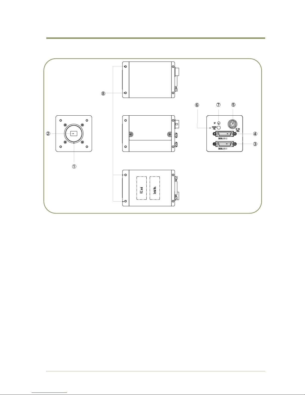
4. Locations and functions
1
Lens Mount
: C-mount (Note 1)
2
CCD Sensor
: 1/3 inch CCD sensor
3
26P Multi Connector
: Camera Link connector Output 1 (Note 2)
4
26P Multi Connector
: Camera Link connector Output 2 (Note 2)
5
12P Multi Connector
: DC+12V and Trigger Input
6
LED
: Power and Trigger indications
7
Push Button
: For Auto Luminance balance
8
Mounting holes
: M3, max length 5mm
(Note 1 )
AD-081CL uses Prism Optics. C-mount lens should be designed for interfacing to
a 3-CCD camera. Rear protrusion of the C-mount lens must be less than 4mm to
avoid damage to the prism.
(Note 2 )
When a Camera Link cable is connected to the camera, please do not
excessively tighten screws by using a driver, as the Camera Link receptacle on
the camera could get damaged. For security, the strength to tighten screws
should be less than 0.291 Newton meter (Nm), (Manufacturer‟s
recommendation). It is sufficient to tighten the screws by fingers.
Fig.1. Locations
Page 9
AD-081CL
- 7 -
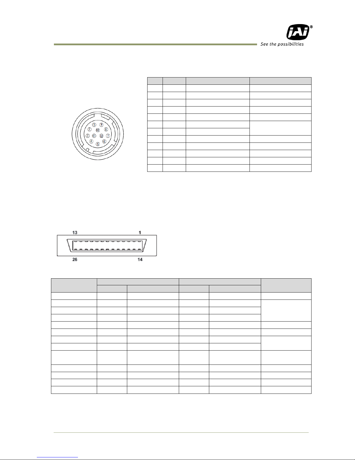
5. Pin configuration
5.1 12-pin multi connector (DC in / Trigger in)
Type: HR-10A-10R-12PB
(Hirose) male
(Seen from rear of the camera)
Fig.2. 12-pin connector
5.2 Digital Output Connector (Camera Link
TM
)
Type: 3M 10226-1A10JL
Fig.3. 26-pin Camera Link connector
Pin No
CameraLink Connector 1
CameraLink Connector 2
Remarks
In/Out
Name
In/Out
Name
1,14
Shield
Shield
GND
2(-),15(+)
O
TxOUT0
O
TxOUT0
Data output
3(-),16(+)
O
TxOUT1
O
TxOUT1
4(-),17(+)
O
TxOUT2
O
TxOUT2
5(-),18(+)
O
TxClk
O
TxClk
Clock for CL
6(-),19(+)
O
TxOUT3
O
TxOUT3
Data output
7(+),20(-)
I
SerTC (RxD)
I
SerTC (RxD)
LVDS serial
control
8(-),21(+)
O
SerTFG (TxD)
O
SerTFG (TxD)
9(-),22(+)
I
CC1 (Trigger)
I
CC1 (Trigger)
External trigger
IN
10(+),23(-)
N.C N.C
11,24 N.C N.C
12,25 N.C N.C
13,26
Shield
Shield
GND
No
In/Out
Name
Remarks
1
GND
2 DC (+12V) in
3
GND
4 O Iris Video
For Auto iris lens
5
GND
6
O
XEEN1
Negative Logic
7
O
XEEN2
8
GND
9
10 I Trigger1
External trigger
11 I Trigger2
External trigger
12
GND
Page 10
AD-081CL
- 8 -
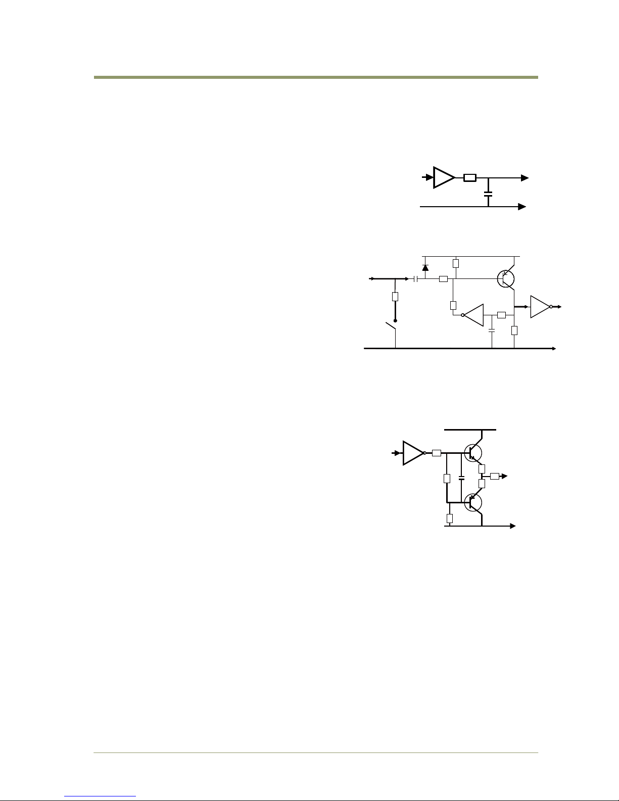
Fig.5. Trigger circuit
Fig.6. XEEN output circuit
5.3 Input and output circuits
In the following schematic diagrams the input and output circuits for video and timing signals
are shown.
5.3.1 Iris Video output
This signal can be used for lens iris control in Continuous mode.
The signal is taken from the CCD sensor output before the gain
circuit. The video output is without sync. The signal is 0.7 V p-p
from 75 without termination. The signal from Imager 1 is used
for this purpose.
5.3.2 Trigger input
An external trigger input can be applied to pin 10
and 11 of 12-pin Hirose connector (when the
command TI1/TI2=1 have been set).
The input is AC coupled. To allow long pulses the
input circuit is designed as a flip-flop circuit. The
leading and trailing edges of the trigger pulse
activate the circuit.
The trigger polarity can be changed by
TP1/TP2=1.
Trigger input level 4 V 2 V.
Trigger can also be applied through the Camera
Link connector, when the commands TI1/TI2=0
have been sent.
5.3.3 XEEN (Exposure Enable) output
XEEN is available on pin 6 and 7 of the 12-pin HR
connector. The output circuit is 75 complementary
emitter followers. It will deliver a full 5 volt signal.
Output level 4 V from 75. (No termination).
EEN is also found in Camera Link.
5.3.4 Camera Link Interface
The video output is possible as 10/8-bit monochrome signals via standard Camera Link
interface.
The pin configuration of 26-pin connector conforms to Camera Link BASE configuration.
However, since AD-081CL camera has various outputs, pin assignment depends on the specific
output mode selected.
For details, please refer the table shown on the next page.
300 mV
500 mV
GND
75
Video
Output
800 mV
300 mV
500 mV
300 mV
500 mV
GND
75
Video
Output
GND
75
Video
Output
800 mV800 mV
Fig.4. Iris video circuit
GND
+5V
15k
TTL
1k
GND
100n
1k
68k
100k
1n
75Ω
SW302.1
GND
+5V
15k
TTL
1k
GND
100n
1k
68k
100k
1n
75Ω
SW302.1
GND
+5V
15k
TTL
1k
GND
100n
1k
68k
100k
1n
75Ω
Trig input
pin #10 & #11
SW302.1
GND
+5V
2
2
10k
2k2
75
TTL
100
Pin #6 & #7
XEEN
output
GND
+5V
2
2
10k
2k2
75
TTL
100
Pin
XEEN
output
Page 11
AD-081CL
- 9 -
Port/
Signal
Camera Link Connector - 1
Camera Link connector - 2
Pin No.
BW1
10bit
output
BW1
8bit
output
BW1
10bit
BW2
10bit
output
* note )
BW1
8bit
BW2
8bit
output
* Note )
BW2
10bit
output
BW2
8bitoutp
ut
BW2
10bit
BW1
10bit
output
* Note )
BW2
8bit
BW1
8bit
output
* Note )
Port A0
BW1_D0
BW1_D0
BW1_D0
BW1_D0
BW2_D0
BW2_D0
BW2_D0
BW2_D0
Tx0
Port A1
BW1_D1
BW1_D1
BW1_D1
BW1_D1
BW2_D1
BW2_D1
BW2_D1
BW2_D1
Tx1
Port A2
BW1_D2
BW1_D2
BW1_D2
BW1_D2
BW2_D2
BW2_D2
BW2_D2
BW2_D2
Tx2
Port A3
BW1_D3
BW1_D3
BW1_D3
BW1_D3
BW2_D3
BW2_D3
BW2_D3
BW2_D3
Tx3
Port A4
BW1_D4
BW1_D4
BW1_D4
BW1_D4
BW2_D4
BW2_D4
BW2_D4
BW2_D4
Tx4
Port A5
BW1_D5
BW1_D5
BW1_D5
BW1_D5
BW2_D5
BW2_D5
BW2_D5
BW2_D5
Tx6
Port A6
BW1_D6
BW1_D6
BW1_D6
BW1_D6
BW2_D6
BW2_D6
BW2_D6
BW2_D6
Tx27
Port A7
BW1_D7
BW1_D7
BW1_D7
BW1_D7
BW2_D7
BW2_D7
BW2_D7
BW2_D7
Tx5
Port B0
BW1_D8
×
BW1_D8
BW2_D0
BW2_D8
×
BW2_D8
BW1_D0
Tx7
Port B1
BW1_D9
×
BW1_D9
BW2_D1
BW2_D9
×
BW2_D9
BW1_D1
Tx8
Port B2
× × ×
BW2_D2
× × ×
BW1_D2
Tx9
Port B3
× × ×
BW2_D3
× × ×
BW1_D3
Tx12
Port B4
×
×
BW2_D8
BW2_D4
×
×
BW1_D8
BW1_D4
Tx13
Port B5
×
×
BW2_D9
BW2_D5
×
×
BW1_D9
BW1_D5
Tx14
Port B6
× × ×
BW2_D6
× × ×
BW1_D6
Tx10
Port B7
× × ×
BW2_D7
× × ×
BW1_D7
Tx11
Port C0
×
×
BW2_D0
× × ×
BW1_D0
Tx15
Port C1
×
×
BW2_D1
× × ×
BW1_D1
Tx18
Port C2
×
×
BW2_D2
× × ×
BW1_D2
Tx19
Port C3
×
×
BW2_D3
× × ×
BW1_D3
Tx20
Port C4
×
×
BW2_D4
× × ×
BW1_D4
Tx21
Port C5
×
×
BW2_D5
× × ×
BW1_D5
Tx22
Port C6
×
×
BW2_D6
× × ×
BW1_D6
Tx16
Port C7
×
×
BW2_D7
× × ×
BW1_D7
Tx17
L V A L
Tx24
F V A L
Tx25
D V A L
Tx26
EEN
Tx23
*Note: When the output mode is set at “Separate“, only one channel signal is output.
For instance, if “BW1 10 bit/ BW2 10 bit” is selected on channel 1, only “BW1 10 bit”
is output when the output mode is set at “Separate“.
Command “IS” is related to this. IS=0 Synchronous and IS=1 Separate
Page 12
AD-081CL
- 10 -
6. Advise on camera settings
6.1 Lens considerations
AD-081CL utilizes prism optics for separating the incident light onto the two CCDs. The camera
employs a C-mount for the lens but for high image quality it is strongly recommended to use
lenses specifically designed for 3-CCD cameras.
6.2 About capture boards
AD-081CL has two Camera Link connectors. In order to capture the signals from both
connectors, two frame grabber boards or a frame grabber board with two inputs are required.
As described in the chapter 7.1.2, the configuration for the outputs can be selected to utilize
only one connector. Therefore, it is still possible to capture images via a frame grabber board
that has only one input.
7. Functions and operations
7.1 Basic functions
The AD-081CL utilizes prism optics to split the incident light onto two monochrome CCDs.
These two images, if captured with different exposure settings, can be combined in the PC to
create high dynamic range output. Alternatively, these two images can be read out in different
timing to achieve a faster frame rate.
The interface to the frame grabber board is Camera Link
TM
BASE configuration and two
connectors are used. Each connector provides 8/10 bit Monochrome signals. These signals can
be output in synchronous mode or separately.
The AD-081CL has continuous mode, pre-select trigger mode, pulse width trigger mode and PIV
(Particle Image Velocimetry) mode. In addition to full frame readout, 1/2, 1/4 and 1/8 partial
scan readouts and vertical binning are available.
The AD-081CL is equipped with automatic detection for LVAL sync or LVAL async mode.
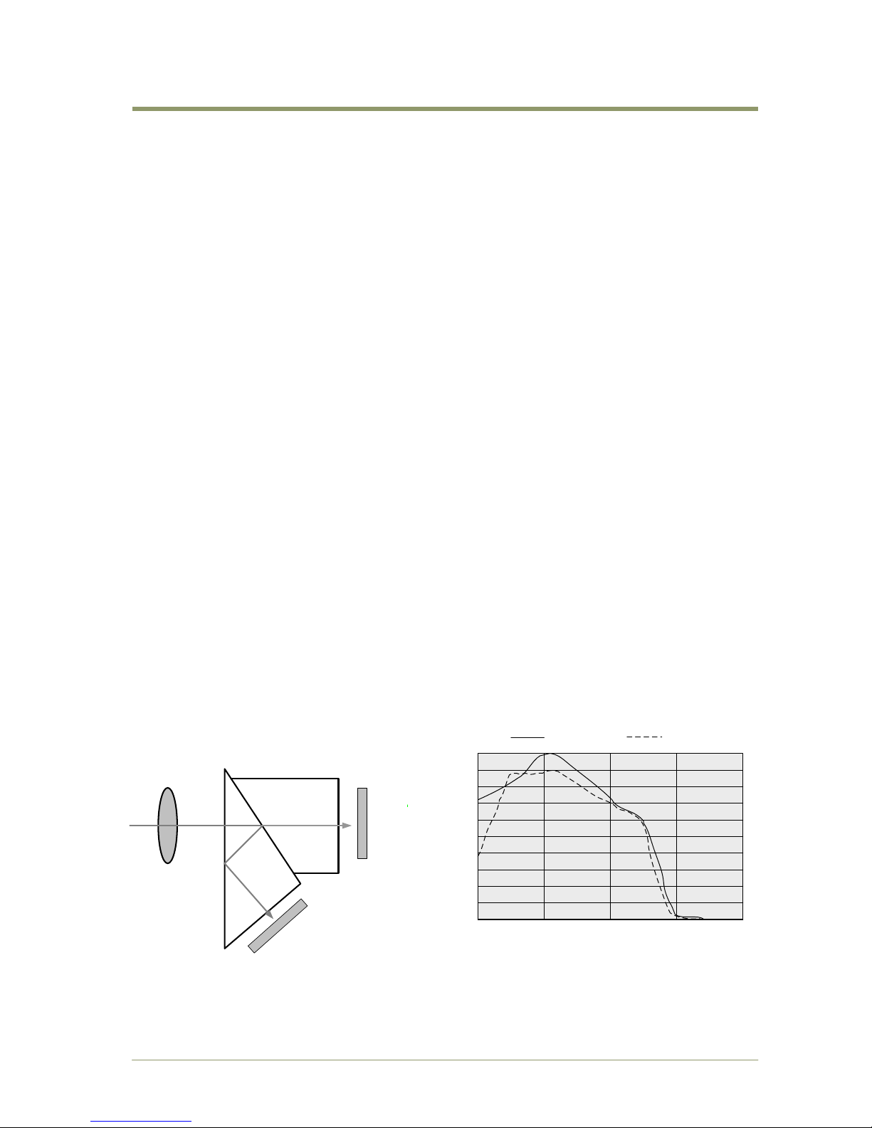
7.1.1 2CCD optical assembly
The AD-081CL incorporates prism optics designed for light in the visible spectrum ranging from
400nm to 650nm wavelengths. 1/2 of the incident light is reflected by the Dichroic Mirror and
provides the input to Imager 2. The other half is transmitted through the prism and provides
the input to Imager 1.
The following conceptual diagram illustrates this process.
Fig 7. The conceptual diagram for 2CCD prism optics
Imager 1
( Transmitted )
Imager 2
(Reflected )
100
90
80
70
60
50
40
30
20
10
400
500
600 700 800
Wave Length ( nm )
Transmittance (%)
BW1 (Transmitted )
BW2 (Reflected )
Page 13
AD-081CL
- 11 -
7.1.2 Configuring Camera Link outputs (Command: OS1, OS2)
The AD-081CL has two Camera Link connectors. These two outputs can be synchronized or
separated by the software command IS. Each connector can output an individual signal or two
signals added as shown below. In order to output two signals through one Camera Link
connector, the output mode must be set at “synchronous”, IS=0.
If it is set at “Separate”, IS=1, the output is automatically limited to one output.
Setting command: IS IS=0 Synchronous IS=1 Separated
Output
IS=0,1
Camera Link 1
Camera Link 2
Comm.゙
Output format
Default
Comm.
Output format
Default
Sync/async
OS1=0
BW1 10 bit
◎
OS2=0
BW2 10bit
◎
Sync/async
OS1=1
BW1 8 bit
OS2=1
BW2 8bit
Sync
OS1=2
BW1+BW2 10bit
OS2=2
BW2+BW1 10bit
Sync
OS1=3
BW1+BW2 8bit
OS2=3
BW2+BW1 8bit
If OS is set to 0 or 1, the camera can be operated in either Synchronous mode or Separate
Mode.
In Synchronous mode, trigger 1 input is effective as a trigger for both BW1 and BW2. In case of
Separate mode, trigger 1 and trigger 2 are both in effect so that different trigger timing can be
applied to each camera.
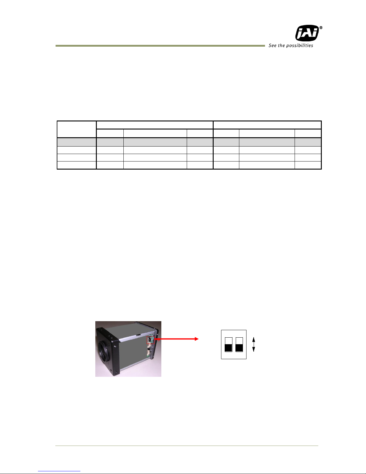
7.1.3 Continuous operation or triggered operation
The AD-081CL can operate in continuous mode to support applications not requiring an external
trigger.
This mode permits the use of a lens with video controlled iris. The AD-081CL uses the signal
from imager 1 (BW1) for this purpose.
The external trigger signal can be input through pins number 10 and 11 of the 12-pin HIROSE
connector.
These inputs can be changed to Camera Link by the command “TI“. When the camera output
is in “Synchronous” mode, trigger 1 input has a priority and controls two imagers. In the case of
“Separate” mode, each imager operates by Trigger 1 and Trigger 2 respectively.
Trigger signal is TTL as the default setting but it can be changed to 75 ohm input by the internal
DIP switch as described in Fig.8.
Fig.8. DIP switch
2
1
O
N
TTL
75Ω
trigger2
Trigger1
SW802
Page 14

AD-081CL
- 12 -
7.1.4 Digital Video output (Bit allocation)
The 10-bit digital output is set at 890 LSB as 100% video
level when CCD output is 200mV.
The white clip level is set at 1023 LSB when CCD output is
230mV.
In case of the 8 bit output, it is set at 222LSB, 255LSB
respectively.
Fig.9. Digital Video Output
7.1.5 Iris Video output
The lens-iris video output on pin 4 of the 12-pin HIROSE is
700 mV for 100% video out in Camera Link. The iris video
signal is taken before the gain circuit. It is without sync.
The iris video signal can be used for auto iris lens drive in
continuous mode only.
Fig.10. Iris Video output
Analog S ignal [mV]
Black Lev el
1023
890
32
0
25
700
Digital O ut [LSB]
White Cli p Level
100% Lev el
800
0
100% Level700
200
Analog Ou t [mV]
CCD Out [ mV] 265
930
Page 15
AD-081CL
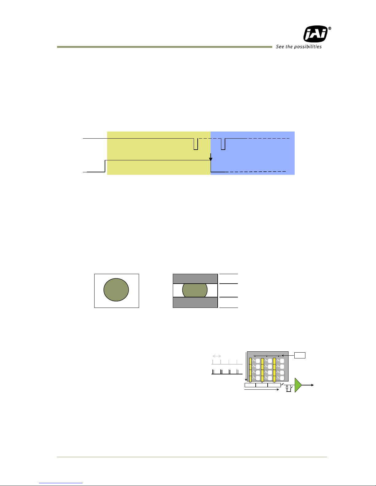
- 13 -
7.1.6 Auto-detect LVAL-sync / async accumulation
This function replaces the manual setting found in older JAI cameras. Whether accumulation is
synchronous or asynchronous in relationship to LVAL depends on the timing of the trigger input.
When a trigger is received while FVAL is high (during readout), the camera works in
LVAL-synchronous mode, preventing reset feed-through in the video signal. There is a
maximum jitter of one LVAL period from issuing a trigger and accumulation start.
If a trigger is received when FVAL is low, the camera works in LVAL-asynchronous mode (no
delay) mode.
This applies to both pre-select (PS) trigger mode and pulse width trigger (PW) mode.
7.1.7 Partial scan and Color Pixels layout
Partial scan allows higher frame rates by reading out a smaller center portion of the image.
This is particularly useful when inspecting objects that do not fill the whole height of the
image.
Full scan Partial Scan
Fig.12. Partial scan
7.1.8 Vertical Binning
The binning functions can be used to achieve
higher frame rate and higher sensitivity. The
drawback is lower resolution.
Vertical binning is done by adding the charge
from pixels in adjacent lines in the horizontal
CCD register.
The AD-081CL uses vertical binning to increase
the frame rate.
Fig. 13 shows the vertical binning principle. Fig.13. Vertical binning
Ext. TRIG
FVAL
(1)
(3)
(1) In this period camera executes trigger at next LVAL (prevents feed-through noise)
(2) Avoid trigger at FVAL transition (+/- 1 LVAL period), as the function may randomly switch
between "next LVAL" and "immediate".
(3) In this period camera executes trigger immediately (no delay)
(2)
Fig.11. LVAL sync/async Automatic Detection
Fast-dump period
Fast-dump period
Normal scan period
H
Xsg1
Video out
No V binning
V binning
H
Xsg1
Video out
No V binning
V binning
Page 16

AD-081CL
- 14 -
7.1.9 Electronic shutter (Commands SM1,SM2,SH1,SH2,PE1,PE2)
The AD-081CL has two shutter modes. One is an 11-step pre-set shutter and the other is a
programmable exposure mode which can be controlled from 0.5L to 792L in one-line
increments.
Pre-set Shutter (SH1 / SH2)
The setting command is from SH1/SH2=0(OFF) to SH1/SH2=11(1/50,000)
OFF(1/30),1/60,1/100,1/120,1/250,1/500,1/1000,1/2,000,1/4,000,1/10,000,1/16,000,1/50,0
00
Programmable Exposure (PE1 / PE2)
The setting command is PE1/PE2 and the exposure time can be controlled in 1 LVAL unit
(42.07µs).
The range is from 0.5LVAL to 792LVAL. (In case of vertical binning, 1 LVAL equals 50.96µs.)
The shutter speed for each operation mode is shown below.
Mode
Read Out
Minimum shutter speed
Maximum shutter speed
Continuous
Full, Partial
20µs at PE=0(1/50,000)
1 Frame
V Binning
30µs at PE=0(1/50,000)
Pre-Select
Full, Partial
20µs at PE=0(1/50,000)
792 L
V Binning
30µs at PE=0(1/50,000)
Pulse Width
Full, Partial
42.07µsx2L+ 20µs=
104.14µs (≒1/10,000s)(Note)
60 Frames ( 2 seconds )
V Binning
50.96µsx2L+ 20µs=
131.92µs (≒1/8,000s)(Note)
Note: In Pulse Width mode, the minimum trigger pulse width requires more than 2LVAL.
Exposure time calculation
Mode
Equality
Full scan
= PE (line) x 1L (42.07µs) + 20 µs (PE= 0 to 791)
1/2 Partial scan
= PE (line) x 1L (42.07µs) + 20 µs (PE= 0 to 491)
1/4 Partial scan
= PE (line) x 1L (42.07µs) + 20 µs (PE= 0 to 347)
1/8 Partial scan
= PE (line) x 1L (42.07µs) + 20 µs (PE= 0 to 275)
Vertical binning
= PE (line) x 1L (50.96µs) + 30 µs (PE= 0 to 395)
Page 17

AD-081CL
- 15 -
7.1.10 PIV (Particle Image Velocimetry) mode
The AD-081CL is equipped with PIV (Particle Image Velocimetry) mode. This mode provides
three (3) consecutive images by one trigger pulse. When the trigger is input, the first exposure
on BW1 can be captured, followed quickly by an exposure on BW2. After the exposure on BW2 is
completed, a second exposure on BW1 is made. Each exposure is executed by a strobe flash in a
very short interval period. The exposure time is preset at 4 µs, 6µs or 8µs by the Trigger mode
command, TR1=4(PIV1), 5(PIV2) or 6(PIV3) respectively.
Trigger
Input
BW 1
EEN
BW 1
Video Output
Strobe Flash
BW 2
EEN
BW 2
Video Output
Exposure 1 image
Exposure 2 Image
Exposure 3 image
Exposure 1
Exposure 2
Exposure 3
1 Frame
Fig.14 PIV conceptual drawing
7.1.11 High Frame Rate function (double speed readout)
A high frame rate (double speed) can be achieved by shifting the exposure timing of BW1 and
BW2 by 1/2 frame duration. As the AD-081CL operates at the rate of 30 fps in continuous mode,
this will produce a rate of 60 fps in high frame rate mode (double speed mode). The shutter
speed must be less than 1/60s (396L). This mode can be set by process mode command HF=1 in
the case of normal mode.
In the case of trigger mode, after setting Output Mode IS=1 (Separate), high frame rate is
achieved by providing a trigger pulse to each camera at 1/2 frame duration.
BW 1 Exposure
BW 1 Image
Output
BW 2 Exposure
BW 2 Image
Output
1/60s 1/60s 1/60s 1/60s 1/60s
1/30s
1/30s
1/30s 1/30s
Fig.15 High Frame rate conceptual drawing
Page 18

AD-081CL
- 16 -
7.1.12 High Dynamic Range function
A CCD camera has ability to capture high speed moving objects or high luminance objects by
using the electronic shutter function. The AD-081CL camera uses this shutter function to
simultaneously capture two images with different shutter speeds. As a result, the AD-081CL can
output two identical images with different video levels, one for capturing the details in the
dark portion and the other for maintaining details in the brightest portions of the image.
In the PC, these images can be composited into a single image providing proper exposure and
details across a wider dynamic range than is normally possible with CCD sensors. In this way the
camera can provide dynamic range equal to specialized CMOS sensors, without the noise
tradeoffs commonly associated with that technology.
The following illustrates the high dynamic range concept.
+
100%
200%
100%
100%
200%
200%
BW 1 Image
Shutter OFF (1/30)
BW 2 Image
Shutter 1/1000
Image in this
part is
clipped
Composite image of BW 1
and BW 2
Although total
video level is
lower but high
light image can be
viewed
⇒
Fig.16 High Dynamic Range Conceptual Drawing
7.1.13 Shading compensation (Commands SDM1,SDM2,RSem Rate mode.1,RS2)
AD-081CL implements a compensation circuit for the white shading which could be caused in
the prism or the optics. This circuit divides the whole image into 128 regions horizontally and
96 regions vertically and compensates the divided video level using the level of the center as
the reference.
There are three memories inside the camera for shading compensation. One is for the factory
setting data and other two memories are for user settings. Commands SDM1 and SMD2 activate
the shading compensation using setting 1, 2 or 3. Setting 1 is for the factory setting, while
settings 2 and 3 are for user settings. When SDM1/SDM2 is set at 2 or 3, the shading
compensation can be executed under operating conditions by commands RS1 and RS2 and
stored in memories.
Note: This image can be
composited at PC.
Page 19

AD-081CL
- 17 -
7.1.14 Knee compensation (Commands KN1,KN2,KSY1/KSY2,KPY1/KPY2)
The camera operates at 12 bits internally and has 1279
LSB dynamic range.
However, the output of AD-081CL is 8-bit or 10-bit and
the data over 1023 LSB (in case of 10-bit) is clipped if
the relationship between IN and OUT is set at linear.
A knee compensation circuit including Knee point and
Knee slope compensates the data up to 1279 LSB for
8-bit or 10-bit output.
The drawing to the right shows the characteristics for
factory default.
Fig.17. Knee characteristics (Default setting)
7.1.15 Automatic luminance balance (Commands AYB,YA)
This function adjusts automatically the video levels for the two monochrome sensors, BW1 and
BW2. The BW2 video level is automatically compensated using BW1 video level as the reference
level.
In order to activate this function, the button on the rear panel can be used. It is also possible to
set by software command AYB via the RS232C communication interface. It may take up to 3
seconds in order to complete Automatic Luminance balance.
Items
Continuous AWB
Adjusting range
-3dB ~ +6dB
Operation on the camera
No
Store the data
No
Measuring area
The area to be used for auto luminance balance adjustment can be selected as the full image
or from one of 9 other areas as shown below.
0: Full area
1: Upper Left
2: Upper Middle
3: Upper Right
4: Middle Left
5: Middle
6: Middle Right
7: Lower Left
8: Lower Middle
9: Lower Right
7.1.16 Rear Panel Indication
The rear panel mounted LED provides the following information:
Amber : Power connected - initiating
Steady green : Camera is operating in Continuous mode
Flashing green: The camera is receiving external trigger
0
1 23
4 5 6
7 8 9
0 32 890
32
890
918
1023
1335
1335
2048
0
128
Knee
Slope
Knee
point
1/16
Input Level
Output Camera Link Data Level
Knee point = 890
Knee Slope = 1/16
In this case : Maximum value is 918 LSB
Page 20

AD-081CL
- 18 -
7.1.17 Test Signal Generator (Commands: PBY1,PBY2)
AD-081CL is equipped with a test signal generator. The following test signals are selected by
commands, PBY1 and PBY2.
PBY1 / PBY2 : 0= Video, 1=Bypass, 2= Test pattern1 (Gradation),
3= Test Pattern 2 (White 100%)
7.1.18 Center marker generator (Commands: CM1,CM2)
The AD-081CL has a center marker generator. Three markers are available, one for Vertical,
one for Horizontal and one for both.
Commands CM1 and CM2 can select one of those markers.
1 = Vertical 2 = Horizontal 3 = Both
7.2 Sensor Layout and Timing
7.2.1 Sensor Layout
The CCD sensor layout, with respect to pixels and lines used in the timing and video full frame
read out, is shown below. For Bayer color sequence, refer to chapter 7.1.7.
Fig.18. Sensor layout and video output image
Blank
Read Out
(Vertical)
1077
Active Pixels
1024(H) x 768(V)
Optical Black Lines
Optical Black Lines
Reserved Lines
Reserved Lines
1024
3 5 5
40 7 5
2
6
Blank
1420 Clock
Read Out (Horizontal)
4
343
768
792
Page 21

AD-081CL
- 19 -
7.2.2 Horizontal Timing
The horizontal timing for continuous mode, full frame and partial scan are shown below.
D A T A O U T
D V A L
C C D O u t
E f f e c t i v e P i x e l s
F V A L
S U B
S G
E E N
F V A L F a l l i n g E d g e
1 L V A L p e r i o d
1 c k = 3 3 . 7 5 0 M H z ( 2 9 .6 3 ns /c k )
F V A L R a i s i n g E d g e
L V A L
X E E N
(Hirose 12pin)
E x p o s u r e
P e r i o d
D u m m y +
B l a n k
8 6
3 4 3 c k
1 4 2 0 c k
1 3 2 8 c k
1 0 2 4 c k
1 0 7 7 c k 3 4 3 c k
( 2 0 u s )
O B R e s e r v e d
3 c k
8 c k
O B
4 0 c k
1 0 2 4 c k
R e s e r v e d
4 5 c k
3 c k5 c k3 4 3 c k
5 c k
5 c k
2 9 c k
2 9 c k
5 9 0 c k
6 7 6 c k
1 0 7 7 c k1 4 8
9 2
1ck1
1 0 3 c k
1CLK : 1 Pixel clock period OB : Optical black
LVAL is HIGH in the period of optical black and effective video periods
DVAL is HIGH in the effective video period
Fig.19. Horizontal Timing
Page 22

AD-081CL
- 20 -
7.2.3 Vertical Timing
The vertical timing for continuous mode and full frame scan are shown below.
2 L6 L 4 L
7 L 5 L
7 6 8 L
E f f e c t i v e L i n e s
7
6
5
7
6
4
7
6
6
7
6
8
7
6
7
R
e
s
e
r
v
e
d
1 2 3 4 5
R e s e r v e d
O B
B l a n kO B
D A T A O U T
D V A L
0 . 5 L
L V A L
S U B
S G
F V A L
E E N
F V A L
L V A L
1 F V A L p e r i o d
E x p o s u r e
P e r i o d
1L = 1420Clock (42.07us)
X E E N
(Hirose 12pin)
7 9 2 L
4 L
7 8 8 L
1L : 1 LVAL period OB: optical black
FVAL is HIGH in the optical black and effective video periods
LVAL is always output
DVAL is output during the effective lines
Fig.20. Vertical Timing
Page 23

AD-081CL
- 21 -
7.2.4 Partial Scan
The vertical timing for continuous mode and partial scan is shown below. The horizontal timing
for partial scan is the same as full scan.
SC
Option
Start
(Line)
End
(Line)
Line
No.
(Lines)
Output Image
Front of
Frame
-A-
Back
of
Frame
-B-
Blank
of
Frame
-C-
0
Full
Screen
1
768
768
Full Frame
12 8 4
1
1/2
Screen
192
576 384
Partial Scan
54
50
4
2
1/4
Screen
288
480 192 78
74
4
3
1/8
Screen
336
432
96
90
86
4
Vertical Timing for 1/2 Partial scan
Dum my
3 L 4 L3 8 4 L1
1 2 3
3
8
1
3
8
0
3
8
2
3
8
4
3
8
3
E f f e c t i v e L i n e s
4
D V A L
D A T A O U T
5
O B
A
5 0 L ( 1 / 2 )
B
5 0 L ( 1 / 2 )
C
5 4 L
4 9 2 L
4 8 8 L 4 L
0 . 5 L
B a c k o f F r a m e
L V A L
S U B
S G
F V A L
E E N
E x p o s u r e
P e r i o d
H i g h S p e e d
T r a n s f e r
F r o n t o f F r a m e
B
l
a
n
k
X E E N
(Hirose 12pin)
1L= 1420Clock (42.07us)
1L : 1LVAL period OB: Optical Black
Fig.21. Vertical Timing for 1/2 Partial scan
Page 24

AD-081CL
- 22 -
Vertical Timing for 1/4 Partial scan
Dum my
1
8
9
1
8
8
1
9
0
1
9
2
1
9
1
E f f e c t i v e L i n e s
4 5
1 2 3
D V A L
D A T A O U T
O B3 L 7 4 L1 9 2 L1 4 L
7 8 L
7 4 L
B
l
a
n
k
B a c k o f F r a m eF r o n t o f F r a m e
1 F V A L p e r i o d
L V A L
S U B
F V A L
E E N
E x p o s u r e
P e r i o d
S G
H i g h S p e e d
T r a n s f e r
3 4 4 L
3 4 8 L
0 . 5 L
4 L
X E E N
(Hirose 12pin)
1Line = 1420Clock (42.07us)
Fig.22. Vertical Timing for 1/4 partial scan
Vertical Timing for 1/8 Partial scan
939294969
5
E f f e c t i v e L i n e s
4 5
1 2 3
D V A L
D A T A O U T
8 6 L3 L 8 6 L 4 L1 9 6 L
O B
9 0 L
B
l
a
n
k
B a c k o f F r a m e
1 F V A L p e r i o d
F r o n t o f F r a m e
L V A L
S U B
S G
F V A L
E E N
E x p o s u r e
P e r i o d
H i g h S p e e d
T r a n s f e r
2 7 6 L
2 7 2 L
0 . 5 L
4 L
X E E N
(Hirose 12pin)
1Line = 1420Clock (42.07us)
Fig.23. Vertical Timing for 1/8 Partial scan
Page 25

AD-081CL
- 23 -
Horizontal Timing (Common for Full and Partial Scans)
DATA OUT
DVAL
CCD Out
Effective Pixels
FVAL
SUB
SG
EEN
FVAL Falling Edge
1 LVAL period
1ck = 33.750MHz (29.63ns/ck)
FVAL Raising Edge
LVAL
XEEN
(Hirose12pin)
Exposure
Period
Dummy+
Blank
86
343ck
1420ck
1328ck
1024ck
1077ck 343ck
(20us)
OB Reserved
3ck
8ck
OB
40ck
1024ck
Reserved
45ck
3ck5ck343ck
5ck
5ck
29ck
29ck
590ck
676ck
1077ck148
92
1ck1
103ck
Fig.24. Horizontal Timing
Page 26

AD-081CL
- 24 -
7.2.5 Vertical binning
The vertical timing chart and horizontal timing for the vertical binning mode is as follows.
Horizontal timing
D A T A O U T
D V A L
C C D O u t
E f f e c t i v e P i x e l s
( 3 0 u s )
F V A L
S U B
S G
E E N
F V A L F a l l i n g E d g e
1 L V A L p e r i o d
1 c k = 3 3 . 7 5 0 M H z ( 2 9. 63 ns / ck )
F V A L R a i s i n g E d g e
L V A L
X E E N
(Hirose 12pin)
E x p o s u r e
P e r i o d
6 4 3
1 7 2 0
1 0 7 7
1 0 2 4
1 0 2 4
1 0 7 7 6 4 3
8 6
1 6 2 8
8 6 c k
D u m m y +
B l a n kR e s e r v e d
8 c k 4 5 c k
4 6 7
9 2 7
1 0 1 3
O B R e s e r v e d
3 c k 5 c k
O B
4 0 c k
6 4 3 5 c k3 c k
5 c k
2 9 c k
2 9 c k
9 2
Fig 25. Horizontal timing for vertical binning mode
12 34 5
D A T A O U T
D V A L
O B E f f e c t i v e L i n e s
2 L3 L 1 L
3
8
1
3
8
0
3
8
2
3
8
4
3
8
3
3 L3 8 4 L
4 L
0 . 5 L
LVAL
FVAL
E E N
E x p o s u r e
P e r i o d
S G
S U B
L V A L
F V A L
1 F V A L P e ri o d
3 9 2 L
3 9 6 L
R
e
s
e
r
v
e
d
R
e
s
e
r
v
e
d
X E E N
(Hirose 12pin)
1L = 1 LVAL ( 50.96 µ) , OB = Optical Black
Fig 26. Vertical timing for vertical binning mode
Page 27

AD-081CL
- 25 -
7.3 Operating modes
The AD-081CL can function as a high frame rate (double speed readout) camera or a high
dynamic range camera. Most of the camera‟s main operating modes can be configured to work
with either camera setup. Only PIV mode is an independent function.
Mode/ Function
High Frame rate (Note 1)
High Dynamic range (Note3)
Output mode ( IS = )
Sync
Separate
Sync
Separate
Operating
Mode
Continuous
−
−
PS mode
( Note 2)
PW mode
( Note 2)
Smearless
( Note 2)
PIV
Read out
Full frame
Partial Scan
Vertical
Binning
Note1) In order to use High Frame Rate mode, Process mode command, HF should be set at
HF=1. At HF=1, the output from BW1 and BW2 is offset by 1/2 frame in continuous
operation.
Note2) When High Frame Rate mode is used with a trigger pulse, the output mode is set at IS=1
and HF should be set at HF=0. Trigger 1 and trigger 2 should be input with 1/2 frame
duration.
Note3) High Dynamic Range is available only in synchronized mode.
AD-081CL has 6 operating modes.
1
TR=0
Continuous
Pre-selected exposure
2
TR=1
Pre-select Trigger ( PS )
Pre-selected exposure
3
TR=2
Pulse Width Trigger ( PW )
Pulse width controlled exposure
4
TR=4
PIV Mode 1
4µs exposure, 1.5µ Pulse duration
5
TR=5
PIV Mode 2
6µs exposure, 1.5µ Pulse duration
6
TR=6
PIV Mode 3
8µs exposure, 1.5µ Pulse duration
7.3.1 High Frame Rate function
This function can achieve 60 frames per second (double frame rate) by combining two 30 fps
video streams which are output in and interleaved manner with 1/2 frame duration. Refer to
the details in section 7.1.11.
The following table shows frame rates at trigger OFF, Continuous mode.
Since the frame rate is 60 fps, the shutter speed must be less than 1/60 (= 396L). In vertical
binning mode, it must be less than 326L.
Read out
Frame rate
Full frame
60 fps
1/2 Partial
96 fps
1/4 Partial
136 fps
1/8 Partial
172 fps
Vertical Binning
99 fps
Page 28

AD-081CL
- 26 -
Basic configuration to use this function
Mode
Setting
Command
Process mode
High frame rate
HF=1
In case of trigger mode
Trigger
PS, PW
TR1/TR2= 1,2
Output mode
Separate
IS=1 ( Separate)
Common setting
Output Select
8 bit, 10 bit
OS1/OS2 = 0 to 3
Scan Format
Full scan, Partial scan
SC1/SC2 = 0 to 3
Vertical Binning
ON/OFF
BI1/BI2= 0,1
Shutter
Preset , Programmable
SW1/SW2 = 0,1
Preset shutter
Shutter speed
SH1/SH2 = 1 to 11
Programmable shutter
Shutter speed ( 1l unit)
PE1/PE2=0 to 396
( 326 binning)
Fig. 27 High Frame Rate Timing (PS trigger, Example)
Page 29

AD-081CL
- 27 -
7.3.2 High Dynamic Range function
A high dynamic range image or video stream can be obtained by compositing during post
processing two images or video streams which have different exposure times.
The maximum dynamic range is achieved when:
One camera is set at 1/30s shutter speed
The other is set at 1/50,000s shutter speed
The dynamic range is 118 dB (s/n = 54dB + exposure time difference of 64 dB)
To use this mode :
Mode
Setting
Command
Trigger
Continuous, PS, PW
TR1/TR2= 1,2
Output mode
Sync
IS=0 ( Sync)
Output Select
8 bit, 10 bit
OS1/OS2 = 0 to 3
Scanning
Full scan, Partial scan
SC1/SC2 = 0 to 3
Vertical Binning
ON/OFF
BI1/BI2= 0,1
Individual setting for BW1 and BW2
Shutter
Preset , Programmable
SW1/SW2 = 0,1
Preset shutter
Shutter speed
SH1/SH2 = 1 to 11
Programmable shutter
Shutter speed ( 1l unit)
PE1/PE2=0 to 396
( 326 binning)
7.3.3 Continuous mode
This mode is used for applications not requiring an asynchronous external trigger.
For timing details, refer to fig. 19 through fig. 26.
To use this mode:
Mode
Setting
Command
Trigger
Continuous
TR1/TR2=0
Output mode
Sync/Separate
IS=0(Sync),IS=1(Separate)
Output Select
8bit, 10bit
OS1/OS2=0 to 3
Scanning
Full/Partial
SC1/SC2 = 0 to 3
Vertical Binning
ON/OFF
BI1/BI2= 0,1
Shutter
Preset / Programmable
SM1/SM2=0、1
Preset Shutter
Shutter speed
SH1/SH2=0 to 10
Programmable Shutter
Shutter speed ( 1L unit)
PE1/PE2=0 to 792
Other functions
Page 30

AD-081CL
- 28 -
7.3.4 Pre-Select trigger mode
An external trigger pulse initiates the capture, and the exposure time (accumulation time) is
defined by the SH or PE commands.
The resulting video signal will start to be read out after the selected shutter time.
For timing details, refer to fig. 19 through fig. 26 and fig. 28.
To use this mode:
Mode
Setting
Command
Trigger
Edge Pre-select(EPS)
TR1/TR2=1
Output mode
Sync/Separate
IS=0(Sync),IS=1(Separate)
Output Select
8bit, 10bit
OS1/OS2=0 to 3
Scanning
Full/Partial
SC1/SC2 = 0 to 3
Vertical Binning
ON/OFF
BI1/BI2= 0,1
Shutter
Preset / Programmable
SM1/SM2=0、1
Preset Shutter
Shutter speed
SH1/SH2=0 to 10
Programmable Shutter
Shutter speed ( 1L unit)
PE1/PE2=0 to 792
Other functions
Trigger Input
Camera Link / HIROSE 12pin
TI1/TI2=0, 1
Important Note:
1
The minimum width of the trigger is 2L. The minimum interval of trigger input is as
follows.
Output mode
IS=0 Sync
Smearless OFF
FVAL(792L) + 3L+(Exposure time difference of BW1
and BW2)
Smearless ON
Smearless Time(198L) +1+ ( longer exposure time
between BW1 and BW2) + FVAL(792L) + 3L
Output mode
IS=1 Separate
Smearless OFF
FVAL(792L) + 3L
Smearless ON
Smearless Time(198L) +1+FVAL(792L)+3L
FVAL(792L) is the FVAL period of continuous operation.
2
In the case that “Output mode” is set at “SYNC”, the trigger input for BW1 has priority.
The exposure time can be set individually, but the output timing is synchronized with the
rising edge of the longer exposure time.
Page 31

AD-081CL
- 29 -
Exposure Delay
(Exposure)
DATA out
Data out Delay
1 to 2L
13 to 14L
Ext.Trig
FVAL
EEN
LVAL
XEEN
(Hirose 12pin)
1L = 1420 clock (42.07us)
14.2us
Exposure Period
Fig.28. PS trigger mode (LVAL async) timing chart
Fig. 29. PS trigger mode (LVAL async details)
Page 32

AD-081CL
- 30 -
Fig.30. PS trigger mode (LVAL sync) timing chart
Exposure Delay
1.5L
Data out Delay
( Exposur e)
DATA out
t1+1L( Max)
Edge Pre-Sel ect m od
e ( Full Frame )
13.5L
Ext . Tri g
FVAL
EEN
LVAL
Exposure Peri od
XEEN
(Hir ose 12pin)
1L = 1420 Cl ock ( 42. 07us )
When the LVAL Sync Accum. : t1=0.5 t o 1.5L
(LVAL sync )
1L: 1LVALPeriod OB : Optical Black
Fig.31. PS trigger mode (LVAL sync details)
Page 33

AD-081CL
- 31 -
7.3.5 Pulse Width trigger mode
In this mode, the accumulation time is equal to the trigger pulse width. Here it is possible to
have long exposure times. For the best image quality, the maximum recommended time is <60
frames (2 seconds), however longer exposures may produce acceptable results depending on
the application.
For timing details, refer to fig. 19 through fig. 26 and fig. 29.
To use this mode:
Mode
Setting
Command
Trigger
Pulse Width (PW)
TR1/TR2=2
Output mode
Sync/Separate
IS=0(Sync),IS=1(Separate)
Output Select
8bit, 10bit
OS1/OS2=0 to 4
Scanning
Full/Partial
SC1/SC2 = 0 to 3
Vertical Binning
ON/OFF
BI1/BI2= 0,1
Other functions
Trigger Input
Camera Link / HIROSE 12-pin
TI1/TI2=0, 1
Important Note:
1
The minimum width of the trigger is 2L. The minimum interval of trigger input is as
follows.
Output mode:
IS=0 Sync
IS=1 Separate
Smearless OFF
In case of Pulse width>FVAL(792L)
Exposure time – 792L + 3L
In case of Pulse width(Min:2L) ≦ 792L
792L + 2L
Smearless ON
In case of Pulse width>FVAL(792L)
Exposure time – 792L + 3L
Incase of Pulse width( Min:199L+2L) ≦ 792L
792L + 2L
FVAL(792L) is the FVAL period of continuous operation.
Fig. 32. PW trigger mode (LVAL async) Timing chart
Page 34

AD-081CL
- 32 -
Fig. 33. PW trigger mode (LVAL sync Details)
Fig. 34. PW trigger mode (LVAL sync) Timing chart
Fig.35. PW trigger mode (LVAL sync details)
In PW mode, when “Smearless ON” is selected, the actual accumulation time is (the trigger
pulse width minus Smearless active period (199L)). If the trigger pulse width is shorter than
199L, the exposure is not active.
Data out Del ay
Delay of Exposure St art
( Exposur e)
DATA out
1 to 2L
13 t o 14L
Ext.Tri g
FVAL
EEN
LVAL
Exposure
Delay of Exposure End
XEEN
(Hir ose 12pin)
1L = 1420 clock ( 42. 07us)Pul se Width mod e( Full Frame) (LVAL aSYNC)
14.2us
32.1us
Period
1. 5L
Data out Delay
Del ay of Exposur e St art
(Exposure)
DATA out
13.5L
Ext. Tri g
FVAL
EEN
LVAL
Exposure
Period
Pul se Wi dth mode(Ful l Frame (LVAL SYNC))
Del ay of Exposur e End
0.5 t o 1. 5L
XEEN
(Hir ose 12pin)
1L = 1420 Clock ( 42.07us )
t1= 0 .5 to 1 .5L
Page 35

AD-081CL
- 33 -
7.3.6 PIV mode (Particle Image Velocimetry)
PIV mode is an independent function and is not to be combined with the High Frame Rate
function, the High Dynamic Range function, or the normal output mode (Sync or Separate). In
this mode, one trigger input provides three consecutive outputs. A strobe light is used for
illumination. PIV has three preset modes.
PIV mode
Exposure time
Trigger Interval
PIV 1
4 µ
1.5 µ
PIV 2
6 µ
1.5 µ
PIV 3
8 µ
1.5 µ
Trigger width
2L( min. ) to 1V ( max.)
To use this mode :
Mode
Setting
Command
Trigger
PIV
TR1=4,5,6
Output Select
8bit, 10bit
OS1/OS2=0 to 3
Scanning
Full/Partial
SC1/SC2 = 0 to 3
Vertical Binning
ON/OFF
BI1/BI2= 0,1
Other functions
Trigger Input
Camera Link / HIROSE 12-pin
TI1/TI2=0, 1
PIV Mode
Trigger Input
EEN
Exposure
Video Output
EEN
Exposure
Video Output
SG
SG
1 Frame
4μs
1.5µs
4μs
Strobe 1
Strobe 2
Strobe 3
B
W
1
B
W
2
Fig. 36. PIV mode timing chart
Page 36

AD-081CL
- 34 -
OB
17L2 3 4 5
7
6
5
7
6
4
7
6
6
7
6
8
7
6
7
6L5L
R
e
s
e
r
v
e
d
2L
OB
R
e
s
e
r
v
e
d
t 2
t 1
788 L
768 L
E f fec t i v e L in e s
EXT. Trigger 1
FVAL
LVAL
SUB
SG
Exposure Period
EEN
XEEN
DATA OUT
DVAL
Min:2L to Max:60V(475 20L)
LVAL sync accum. : t1=0.5L to 1 .5L, t2=1.5L
LVAL a-sync accum. : t1=0. 5L t2=1.0L to 2.0L
7.3.7 Smearless mode
This function can reduce the smear on highlights within the image. This is effective for both PS
and PW trigger modes. Before the accumulation starts, stored charges are read out at high
speed. This can reduce the smear in the upper areas of the object without affecting the lower
areas. At the trailing edge of the trigger pulse, the high speed readout starts. This period is
198L. The residual charges in the horizontal transfer gate are read out in 1L and the exposure
starts. This function is available for both full scan and partial scan.
OB
17L2 3 4 5
7
6
5
7
6
4
7
6
6
7
6
8
7
6
7
R
e
s
e
r
v
e
d
2L
OB
R
e
s
e
r
v
e
d
t2
t1
19 8L
788L
768L
E f f ec t i ve L ine s
6L5L
Min: 200L(198L+2L) to Max:6 0V(47520L)
EXT. Trigger 1
FVAL
LVAL
SUB
SG
Exposure Period
EEN
XEEN
DATA OUT
DVAL
LVAL sync accum. : t1=0.5L to 1.5L, t2= 1.5L
LVAL a-sync accum. : t1=0.5L t2=1.0L to 2.0 L
Smear Less Transfer
Fig 37. PW timing chart with Smearless OFF
Fig 38. PW timing chart with Smear less ON
Page 37

AD-081CL
- 35 -
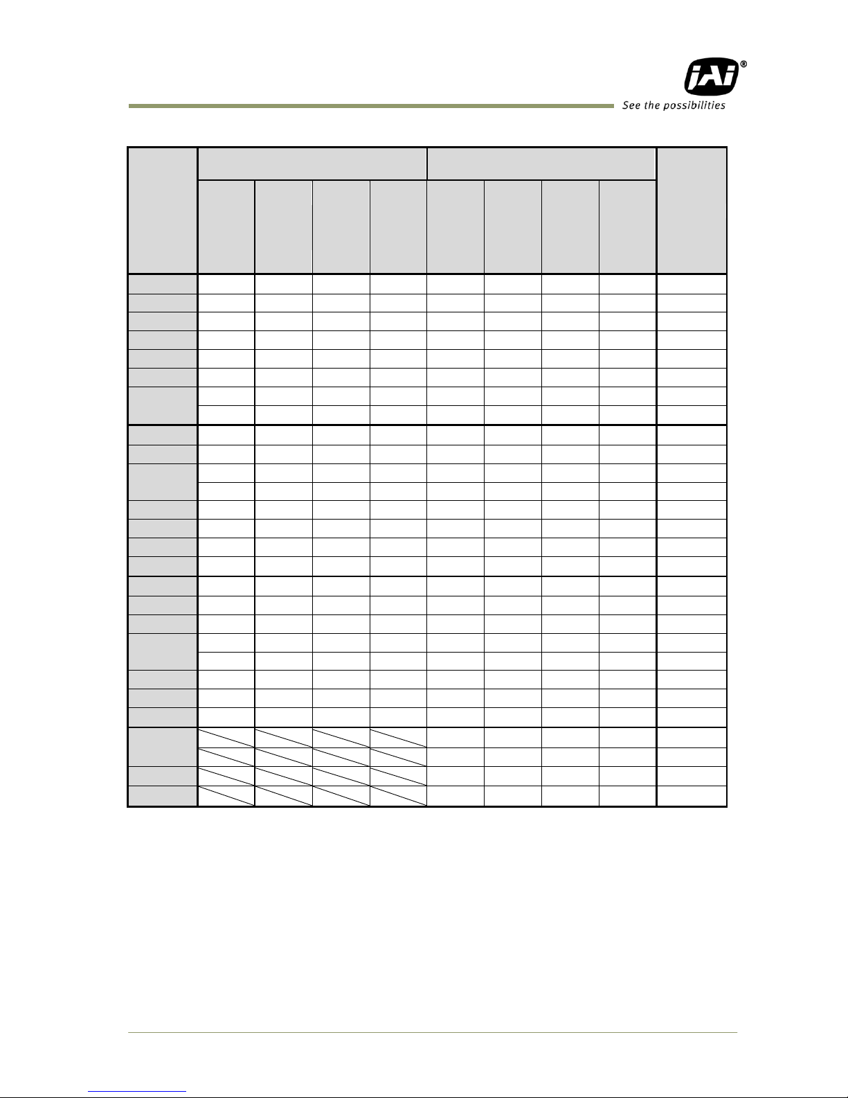
7.4 Modes and functions matrix
AD-081CL has two output modes when the external trigger pulse is used. One is “Synchronous”
mode and the other is “Separate” mode. In Synchronous mode, two Camera Link outputs are
synchronized with each other, whereas in Separate mode, two Camera Link outputs are not
synchronized.
The following table shows modes and functions matrix.
BW1 Imager ( 1)
BW2 imager (2)
Output
mode
IS=
Operation
Trig.
IN 1
Shutter
Partial
Smear
Less
TRIG.
IN 2
Shutter
Partial
Smear
Less
Auto
Iris
TR
Mode ゙
IS=0
Sync
0
Cont.
−
Yes
Yes
No − Yes No
Yes
Note
1
PS
Yes
Yes
Yes
Yes
No
Yes
2 PW
Yes
No
Yes
Yes
No
No
IS=1
Separate
0
Cont.
−
Yes
Yes
No − Yes
Yes
No
Yes
Note
1
PS
Yes
Yes
Yes
Yes
Yes
Yes
Yes
Yes 2
PW
Yes
No
Yes
Yes
Yes
No
Yes
Yes
− 4
PIV1
Yes
No
Yes
No − − − −
5
PIV2
Yes
No
Yes
No − − − −
6
PIV3
Yes
No
Yes
No − − − −
− : not related to , : Use BW1 imager (1) setting
Note: The analog output for auto iris uses the signal from BW1 imager (1).
Page 38

AD-081CL
- 36 -
8. Configuring Camera
8.1 Serial communications
All configuration of the AD-081CL camera is done by LVDS via Camera Link. Baud rate is 9600
bps. The camera can be set up from a PC running terminal emulator software, or through a
graphical user interface (GUI) using JAI's camera control software.
Below is the description of the ASCII-based short command protocol.
Communication Settings
Protocol.
Transmit setting to camera:
NN=Parameter<CR><LF>
(NN is any kind of command. Capital or small letters.)
The camera answers:
COMPLETE<CR><LF>
To have all communication visible on the emulator screen, start with:
EB=1<CR><LF>
The camera answers:
COMPLETE<CR><LF>
Transmit request command to camera:
NN?<CR><LF> (NN is any kind of command.)
The camera answers:
NN=Parameter<CR><LF>
Transmit the following to have the camera actual setting:
ST?<CR><LF>
The camera answers:
A complete list of the current settings
Transmit the following to have a command list:
HP?<CR><LF>
The camera answers:
A list with all commands and possible settings
Invalid parameters send to camera: (99 is an invalid parameter)
SH=99<CR><LF>
The camera answers:
02 Bad Parameters!!<CR><LF>
To see firmware number.
VN?<CR><LF>
To see camera ID. It shows the manufacturing lot number.
ID?<CR><LF>
Baud Rate
9600 bps
RS 232C cable
Data Length
8 bit
Start Bit
1 bit
Stop Bit
1 bit
Parity
None
Xon/Xoff Control
None
TXD
RXD
GND
1 CD
4 DTR
6 DSR
2 RXD
3 TXD
5 GND
7 RTS
8 CTS
9 CI
9 pin
D-con
PC COM
PORT
CAMERA
TXD
RXD
GND
1 CD
4 DTR
6 DSR
2 RXD
3 TXD
5 GND
7 RTS
8 CTS
9 CI
9 pin
D-con
PC COM
PORT
CAMERA
Page 39

AD-081CL
- 37 -
8.2 Setting functions
8.2.1 Output mode (Command IS)
AD-081CL has two imagers and this function selects synchronized output for both
imagers or individual output for each imager. This function should be set at first.
IS=0 is synchronous output and IS=1 is separate output.
8.2.2 Trigger input select (Command TI1 and TI2)
This function selects the trigger input to be through Camera Link (TI1/TI2 =0), or as TTL
through the 12-pin Hirose connector (TI1/TI2 =1).
8.2.3 Trigger mode (Command TR1 and TR2)
This can select continuous mode (0), PS (1) or PW (2).
8.2.4 Trigger polarity (Command TP1 and TP2)
The active trigger polarity is normally low (TP1/TP2 =0). It can be inverted to active
high (TP1/TP2 =1).
8.2.5 Smearless (Command SL1 and SL2)
This command selects Smear ON (1) or OFF (0).
8.2.6 Scan Format (Command SC1 and SC2)
4 scan formats, full scan, 1/2 partial, 1/4 partial or 1/8 partial scan can be selected by
this command.
8.2.7 Gain Master level (Command GA1 and GA2)
GA1/GA2 =0 is 0dB gain, which is the normal working point. The range is from -3 dB to
+12 dB.
8.2.8 AGC select (Command AGC1 and AGC2)
Select AGC ON (1) or OFF (0).
8.2.9 Setup-Y (Command BLY1 and BLY 2)
Valid range for settings is -128 to 256
The black level for 10-bit output is set at 32 LSB and that for 8-bit output is set at 8 LSB.
8.3 Load and Save functions
The following commands are for storing and loading camera settings in the camera EEPROM.
Load settings. LD.
This command will load previously stored settings to the camera. 3 user settings can be stored
in the camera EEPROM. 1 factory setting is also stored in the camera. The settings stored in the
last used user area are used as default settings at power up.
Save Settings. SA.
This command will store the actual camera settings to 1 of the 3 user areas in the camera
EEPROM.
EEPROM Area. EA.
If received, the camera will return the last used user area number.
Page 40

AD-081CL
- 38 -
8.4 AD-081CL Command list
Command
Format
Parameter
Remarks
A – General settings and utility commands ゙
1
Echo Back
EB=[Param.]<CR><LF>
EB?<CR><LF>
0=Echo off
1=Echo on
Off at power up
2
Camera Status
Request
ST?<CR><LF>
Actual setting
3
Online Help Request
HP?<CR><LF>
Command list
4
Firmware Version
VN?<CR><LF>
3 digits, (e.g.)
100 = Ver. 1.00
5
Camera ID Request
ID?<CR><LF>
Max 10 characters
6
Model Name Request
MD?<CR><LF>
Max 10 characters
7
User ID
UD=[Param.]<CR><LF>
UD?<CR><LF>
User can save and
load free text. (16
or less characters)
B – BW1, BW2 Common settings
1
Output Mode
IS=[Param.]<CR><LF>
IS?<CR><LF>
0 = SYNC
1 = Separate
2
V Binning
BI1=[Param.]<CR><LF>
BI1?<CR><LF>
0 = OFF
1 = ON
3
One-push AYB
AYB=[Param.]<CR><LF>
O = One push AYB activated
4
Inquire the status
after one–push AYB
AYB?<CR><LF>
5
AYB area
YA=[Param.]<CR><LF>
YA?<CR><LF>
0=Full area 1=Upper left
2=Upper mid 3=Upper right
4=Middle left 5=Middle
6=Mid. Right 7=Lower left
8=Lower mid. 8=Lower right
C – Shutter
1
Shutter Mode
SM1=[Param.]<CR><LF>
SM1?<CR><LF>
0=Preset Shutter
1=Programmable exposure
For Imager BW1
SM2=[Param.]<CR><LF>
SM1?<CR><LF>
For Imager BW2
2
Preset Shutter
SH1=[Param.]<CR><LF>
SH1?<CR><LF>
0=Off, 1=1/60, 2=1/100,
3=1/120, 4=1/250, 5=1/500,
6=1/1000, 7=1/2000,
8=1/4000, 9=1/8000
10=1/16000, 11=1/50000
Available when
SM1=0
3
Preset Shutter
SH2=[Param.]<CR><LF>
SH2?<CR><LF>
0=Off, 1=1/60, 2=1/100,
3=1/120, 4=1/250, 5=1/500,
6=1/1000, 7=1/2000,
8=1/4000, 9=1/8000
10=1/16000, 11=1/50000
Available when
SM2=0
Page 41

AD-081CL
- 39 -
Command
Format
Parameter
Remarks
3
Programmable
Exposure
PE1=[Param.]<CR><LF>
PE1?<CR><LF>
0 to 792
Available when
SM1=1
PE2=[Param.]<CR><LF>
PE2?<CR><LF>
Available when
SM2=1
D – Trigger mode
1
Trigger Mode
TR1=[Param.]<CR><LF>
TR1?<CR><LF>
0=Normal (Continuous)
1=PS(Pre select)
2=PW (Pulse width)
4=PV1
5=PV2
6=PV3
For Imager BW1
TR2=[Param.]<CR><LF>
TR2?<CR><LF>
For Imager BW2
2
Trigger Polarity
TP1=[Param.]<CR><LF>
TP1?<CR><LF>
0=Active Low
1=Active High
For Imager BW1
TP2=[Param.]<CR><LF>
TP2?<CR><LF>
For Imager BW2
3
Trigger Input
TI1=[Param.]<CR><LF>
TI1? <CR><LF>
0=Camera Link
1=Hirose 12-pin
For Imager BW1
TI2=[Param.]<CR><LF>
TI2? <CR><LF>
For Imager BW2
4
Smearless
SL1=[Param.]<CR><LF>
SL1? <CR><LF>
0=OFF
1=ON
For Imager BW1
Available when
TR1=1 or 2
SL2=[Param.]<CR><LF>
SL2? <CR><LF>
For Imager BW2
Available when
TR2=1 or 2
E – Image Format
1
Scan Format
SC1=[Param.]<CR><LF>
SC1? <CR><LF>
0=Full Frame
1=1/2 Partial
2=1/4 Partial
3=1/8 Partial
For Imager BW1
SC2=[Param.]<CR><LF>
SC2? <CR><LF>
For Imager BW2
2
Output Select
OS1=[Param.]<CR><LF>
SC1? <CR><LF>
0=Imager 1 10 bit
1=Imager 1 8bit
2=Imager 1 +Imager 2 10bit
3=Imager 1+Imager 2 8bit
For Imager BW1
OS2=[Param.]<CR><LF>
SC2? <CR><LF>
0=Imager 2 10bit
1=Imager 2 8bit
2=Imager 2+Imager 1 10bit
3=Imager 2+Imager 1 8bit
For Imager BW2
F – Gain, White Balance, Black
1
Gain-master
GA1=[Param.]<CR><LF>
GA1?<CR><LF>
-84 to 336
For Imager 1
GA2=[Param.]<CR><LF>
GA2?<CR><LF>
-84 to 336
For Imager 2
Page 42

AD-081CL
- 40 -
Command
Format
Parameter
Remarks
2
Setup Level Y
BLY1=[Param.]<CR><LF>
BLy2?<CR><LF>
-128 to 256
For Imager 1
BLY2=[Param.]<CR><LF>
BLy2?<CR><LF>
For Imager 2
3
AGC Select
AGC1=[Param.]<CR><LF>
AGC1?<CR><LF>
0=AGC OFF
1=AGC ON
For Imager 1
AGC2=[Param.]<CR><LF>
AGC2?<CR><LF>
For Imager 2
4
AGC Reference
AGR1=[Param.]<CR><LF>
AGR1?<CR><LF>
0 to 1023
For Imager 1
AGR2=[Param.]<CR><LF>
AGR2?<CR><LF>
For Imager 2
G – Knee function
1
Knee ON/OFF
KN1=[Param.]<CR><LF>
KN1?<CR><LF>
0=OFF
1=ON
For Imager BW1
KN2=[Param.]<CR><LF>
KN2?<CR><LF>
For Imager BW2
2
Knee Slope Y
KSY1=[Param.]<CR><LF>
KSY1?<CR><LF>
0 to 4095
For Imager BW1
KSY2=[Param.]<CR><LF>
KSY2?<CR><LF>
For Imager BW2
3
Knee Point Y
KPY1=[Param.]<CR><LF>
KPY1?<CR><LF>
0 to 1023
For Imager BW1
KPY2=[Param.]<CR><LF>
KPY2?<CR><LF>
For Imager BW2
H – Shading Compensation
1
Shading correction
mode
SDM1=[Param.]<CR><LF>
SDM1?<CR><LF>
0=OFF
1=Factory setting
2=User 1
3=User2
For Imager BW1
SDM2=[Param.]<CR><LF>
SDM2?<CR><LF>
For Imager BW2
2
Recalibrate Shading
Corr.
RS1=[Param.]<CR><LF>
O=User 1
1=User 2
For Imager BW1
RS2=[Param.]<CR><LF>
For Imager BW2
3
Inquire the status
after shading
correction
RSS1?<CR><LF>
0=Shading correction in
process
1=Succeeded
2=Error 1- Image too bright
3=Error 2- Image too dark
4=Error 3- Time out
For Imager BW1
RSS2?<CR><LF>
For Imager BW2
Page 43

AD-081CL
- 41 -
Command
Format
Parameter
Remarks
I – Other functions
1
Process Bypass
PBY1=[Param.]<CR><LF>
PBY1?<CR><LF>
0=Video
1=Bypass
2=Test Pattern 1
3=Test Pattern 2
For Imager BW1
PBY2=[Param.]<CR><LF>
PBY2?<CR><LF>
0=Video
1=Bypass
2=Test Pattern 1
3=Test Pattern 2
For Imager BW2
2
Center Marker
CM1=[Param.]<CR><LF>
CM1?<CR><LF>
0=OFF 1=Vertical
2=Horizontal 3=BOth
For Imager BW1
CM2=[Param.]<CR><LF>
CM2?<CR><LF>
For Imager BW2
F – Saving and loading setting for EEPROM
1
Load Settings
(from Camera
EEPROM)
LD=[Param.]<CR><LF>
0=Factory area
1=User 1 area
2=User 2 area
Latest used DATA
AREA will become
default at next
power up
2
Save Settings
(to Camera EEPROM)
SA=[Param.]<CR><LF>
1=User 1 area
2=User 2 area
“0” is prohibited.
3
EEPROM Current Area
No Request.
EA?<CR><LF>
0=Factory area
1=User 1 area
2=User 2 area
The camera returns
latest used DATA
AREA
Page 44

AD-081CL
- 42 -
9. AD-081CL Camera Control Tool
The Camera Control Tool for Windows 2000/XP can be downloaded from www.jai.com.
The control tool contains a camera control program and a developer's kit for integrating the
control tool in your own software. For the integrator and experienced user, the Camera Control
Tool is much more than a program with a Windows interface. It also provides an easy and
efficient ActiveX interface built for MS Windows 2000/XP. The OCX interface has the ability to
connect to the camera using the serial interface of the PC by reading and writing properties for
the camera. This integration requires simple programming skills within Visual Basic, Visual C++
or similar languages in a Microsoft Windows environment.
9.1 Camera Control Tool Interface
The Camera Control Tool Software is based on a main Tool Bar and a number of associated Tool
Windows. Each button in the Tool Bar pops up a separate Tool Window when pressed. The
layout of the program can be adjusted by arranging the windows the way it is preferred. The
program will store this information and recreate this layout, when the program is restarted. All
Camera Control Tools have a Communication Window and an About Window. The other
window(s) contains camera control commands.
9.1.1 Camera Control Tool Bar
This is a Camera Control Tool Bar and when the button of each window is selected, each control
GUI can be initiated.
9.1.2 The About Window
The about window contains information about the version of the program, Internet connection
to JAI A/S and access to the help documents.
The drop-down box labeled "Help File" will list all files which have the extension .pdf and that
are found in the program (default) folder.
It is possible to download updated
operation manuals from the jai website:
http://www.jai.com
At the bottom of the windows (all windows
but the Communication Window) is a
colored bar. The bar is green when the
Camera Control Tool is connected to a
camera and the camera is turned on. The
bar is red when the Camera Control Tool is
not connected to a camera or when the camera is turned off.
About Window
Communication Window
Camera Control Window
❶ for Imager 1 (BW1) and ❷ for Imager 2
Common Control Window
Page 45

AD-081CL
- 43 -
9.1.3 Communication Window
The Communication Window is used to connect the Camera Control Tool with the JAI camera.
Camera Link communication:
Select “Camera Link” in the
“Category” box. “Port Name”
indicates DLL file names (or frame
grabber names) for all Camera Link
frame grabbers that are installed in
the pc. This is done by using a DLL file
called "clserial.dll" to upload all
frame grabber DLLs that are found on
the pc.
Just select the option for the frame
grabber that is installed in the pc.
Auto search
Click the auto button to search for a
camera on communication port 1 to
16. The camera control program
automatically sends a camera request
on every communication port. The
user is prompted to use a
communication port if a camera
answers the request.
Off/On-line mode
The Camera Control Tool Application can run Offline (without a camera attached)
and all functions are fully functional in offline mode.
Off line mode is indicated in The Communication Window, where a status field with
graphic and text indicates the on/off-line status.
Changing the selected communication port (from the communication window) changes the
online/off-line status. If a camera is found on the selected communication port the application
runs online otherwise offline.
Changing the settings in the application will automatically update the camera settings when
the application is online.
If the application looses connection with the camera it will automatically go to offline mode
and it is indicated in the communication window.
Synchronize program and camera
The Camera Control software has the ability to synchronize either the camera
or the program. Click Synchronize camera to write all settings from the
program to the camera or click the Synchronize program to load all settings
from the camera to the program.
Files
When clicking the Write to File or Read from File button, the user is prompted for a file using a
standard file dialog. New files are created if they do not already exist.
Files for camera settings have the extension cam. Information about the communication port is
not stored in the files. All settings are automatically sent to the camera when a file has been
loaded (if the camera is online).
Page 46

AD-081CL
- 44 -
Factory and User Settings
Use the Store button to store the current camera settings into the user settings area in EEPROM.
Current camera settings are not saved when the camera is turned off. To save current camera
settings you have to save them in one of the available user areas.
Use the Load button to restore previously saved camera settings from either the Factory or the
User EEPROM area.
Write All Camera Data to File.
Click the “Write Camera Data” button to save all camera settings into a
text file. The information that can be saved is:
Model Name, Camera ID, User ID, Firmware Version, Current Settings,
Factory Settings and the available User Areas.
EEPROM Current Area.
Click the „Get Area‟ button to read the power up settings area number.
9.1.4 Common Control window
In this window, the output mode can be selected, synchronous
or separate. The output from Camera Link connector 1 and 2 is
also selected in this window.
9.1.5 Camera Control Window
The Camera Control Window contains
the fundamental camera setting
functions.
It is possible to set the shutter mode,
trigger mode, image format, scan
format, gain control and black setting.
AD-081CL has two camera control
windows, one for Imager 1 and the
other for Imager 2. The right hand side
picture is for Imager 1, BW1.
Page 47

AD-081CL
- 45 -
This picture is for Imager 2, BW2.
9.2 Using the Camera Control Tool
Here is some practical information about the Camera Control Tool:
1. The Camera Control Tool bar is always on top of other windows.
2. When you minimize the Camera Control Tool bar all open windows will close.
3. It is possible to work with the Camera Control Tool when the camera is online or when
the camera is offline.
4. The newer JAI cameras always start up with the last used user area (but for some old
models it will start up with the last saved user area.)
5. The Camera Control Tool saves the last used settings (not the user area), which don‟t
have to be the same as for the last saved user area.
6. The setup file „CameraName.ini‟ stores all information about camera settings. When
the program is started the last settings for the program are loaded from the file
„CameraName.ini‟
7. When you turn on the camera and the Camera Control Tool, it is possible that the
Camera Control Tool does not show the actual camera settings (see 4. and 5.).
a. To obtain the camera settings click “Synchronize Program”.
b. To send the settings that are saved in the Camera Control Tool (last used
settings) to the camera click “Synchronize Camera”.
c. To see which area the camera has started up in click “Get Area”.
Page 48

AD-081CL
- 46 -
10. External Appearance and Dimensions
Fig. 39. Dimensions
Page 49

AD-081CL
- 47 -
11. Specifications
11.1 Spectrum response
Fig. 40. Spectrum response
Fig.41. Total Spectrum response including prism and sensor
Page 50

AD-081CL
- 48 -
11.2 Specifications Table
Specifications
AD-081CL
Scanning system
Progressive scan
Frame Rate Full scan
30 frames/sec. Progressive (768 lines/frame)
High Frame Rate mode : 60 frames / sec. (768 lines/frame)
Pixel clock
33.75MHz
Line frequency
23.768 KHz (1420 pixel clocks/line)
Image sensor
1/3 inch Monochrome IT CCD (ICX204AL)
Sensing area
4.76 (H) x 3.57 (V) mm (1/3 inch diagonally)
Cell size
4.65 (H) x 4.65 (V) µm
Active pixels
1024(H) x 768 (V)
Pixels in Video output Full
1/2 Partial
1/4 Partial
1/8 Partial
V Binning
1024 (h) x 768 (v) 30fps/60fps H = 23.768 kHz
1024 (h) x 384(v) 48fps/96fps H = 23.768 kHz
1024 (h) x 192 (v) 68 fps/136fps H = 23.768 kHz
1024 (h) x 96 (v) 86fps/172fps H = 23.768Hz
1024 (h) x 384 (v) 49.5 fps/99fps H= 19.622 KHz
Minimum Sensitivity on sensor
1.1 Lux
Max. Gain, Shutter OFF, 50% Video Level
S/N ( dB)
More than 54dB (0dB gain)
Iris video output, Analogue
0.7 V p-p (without Sync)
Digital Video Output
Via Camera Link connector 1
BM1_10bit, BW1_10bit+BW2_10bit, BW1_8bit, BW1_8bit+BW2_8bit
Via Camera Link connector 2
BM2_10bit, BW2_10bit+BW1_10bit, BW2_8bit, BW2_8bit+BW1_8bit
Note: Synchronized or separate output is selectable.
Input signal
Trigger(TTL/75Ω)x 2 via Camera Link or HIROSE 12P
Output signal
Hirose 12P XEEN(TTL/75Ω) x 2
Camera Link 1,2: EEN、FVAL,LVAL,DVAL,PCLK (LVDS)
Gain
Master Gain: -3dB ~ +12dB
Knee compensation
Knee point, Knee slope ( 10bit/8bit)
Gamma
1.0 fixed
Shading compensation
ON/OFF
Auto luminance balance
Gain setting range: -3dB to +6dB (High Frame Rate mode)
Detection area is selectable from 9 divisions.
Synchronization
Int. X-tal
Trigger mode
Pre-select, Pulse width and PIV mode
Accumulation
LVAL synchronous or LVAL a-synchronous automatic selection
Preset shutter speed
11steps: OFF(1/30),1/60,1/100,1/120,1/250,1/500,1/1000,1/2000,
1/4000,1/10,000,1/16,000,1/50,000 sec.
Programmable exposure
0.5 L to 792L (1 LVAL unit)
Pulse width control
1/10,000 sec. to 2 seconds
Control interface
Camera Link x 2 (EIA-644 LVDS)
Effective for the first established communication port
Lens Mount
C Mount (Rear protrusion on C mount lens must be less than 4mm)
The lens should be designed for 3CCD cameras
Operating temperature
-5C to +45C
Operating humidity
20 to 80% ( non-condensing )
Storage temperature/humidity
-25C to +60C/20% ~ 80% (non-condensing)
Vibration
3G (15Hz to 200Hz XYZ)
Shock
50G
Page 51

AD-081CL
- 49 -
Specifications
AD-081CL
Regulatory
CE (EN61000-6-2,EN61000-6-3), FCC Part15 Class B、RoHS
Power
DC +12V ± 10%, 0.32A (Typical, normal operation)
Dimensions
55(H)x55(W)x80(D) mm
Weight
400g
Note: Above specifications are subject to change without notice.
Note: Approximately 30 minute pre-heating required to meet specifications.
Page 52

AD-081CL
- 50 -
12. Appendix
12.1 Precautions
Personnel not trained in dealing with similar electronic devices should not service this camera.
The camera contains components sensitive to electrostatic discharge. The handling of these
devices should follow the requirements of electrostatic sensitive components.
Do not attempt to disassemble this camera.
Do not expose this camera to rain or moisture.
Do not face this camera towards the sun, extreme bright light or light reflecting objects,
including laser sources.
When this camera is not in use, put the supplied lens cap on the lens mount.
Handle this camera with the maximum care.
Operate this camera only from the type of power source indicated on the camera.
Remove power from the camera during any modification work, such as changes of jumper and
switch settings.
12.2 Typical Sensor Characteristics
The following effects may be observed on the video monitor screen. They do not indicate any
fault of the camera, but are associated with typical sensor characteristics.
V. Aliasing
When the camera captures stripes, straight lines or similar sharp patterns, jagged image on the
monitor may appear.
Blemishes
All cameras are shipped without visible image sensor blemishes.
Over time some pixel defects can occur. This does not have a practical effect on the operation
of the camera. These will show up as white spots (blemishes).
Exposure to cosmic rays can cause blemishes to appear on the image sensor. Please take care
to avoid exposure to cosmic rays during transportation and storage. It is recommended using
sea shipment instead of air flight in order to limit the influence of cosmic rays to camera.
Pixel defects/blemishes also may emerge due to prolonged operation at elevated ambient
temperature, due to high gain setting or during long time exposure. It is therefore
recommended to operate the camera within its specifications.
Patterned Noise
When the sensor captures a dark object at high temperature or is used for long time integration,
fixed pattern noise may appear in the image.
12.3 Caution when mounting a lens on the camera
When mounting a lens on the camera dusts particles in the air may settle on the surface of the
lens or the image sensor of the camera. It is therefore important to keep the protective caps on
the lens and on the camera until the lens is mounted. Point the lens mount of the camera
downward to prevent dust particles from landing on the optical surfaces of the camera. This
work should be done in a dust free environment. Do not touch any of the optical surfaces of the
camera or the lens.
12.4 Exportation
When exporting this product, please follow the export regulation of your own country.
Page 53

AD-081CL
- 51 -
12.5 References
1. This manual for AD-081CL can be downloaded from www.jai.com
2. Datasheet for AD-081CL can be downloaded from www.jai.com
3. Camera control software can be downloaded from www.jai.com
4. Specifications for the CCD sensor Sony ICX-204AL can be found on www.jai.com
Page 54

AD-081CL
- 52 -
Revisions
Date
Revision
Changes
Feb.2009
1.0
New issue
July 2012
1.1
Correct the drawing, Fig. 39
Page 55

AD-081CL
- 53 -
User's Record
Camera type: AD-081CL
Revision: ……………..
Serial No. ……………..
Firmware version. ……………..
For camera revision history, please contact your local JAI distributor.
User's Mode Settings.
User's Modifications.
Company and product names mentioned in this manual are trademarks or registered trademarks of their respective owners.
JAI A-S cannot be held responsible for any technical or typographical errors and reserves the right to make changes to products and
documentation without prior notification.
Europe, Middle East & Africa
Asia Pacific
Americas
Phone +45 4457 8888
Fax +45 4491 3252
Phone +81 45 440 0154
Fax +81 45 440 0166
Phone (toll-free) +1 800 445
5444
Phone +1 408 383 0300
Visit our web site at www.jai.com
 Loading...