

Page 1
IIT Camera Systems
In Image Triggering Cameras
VIS-CAM 350 IIT
VIS-CAM 400 IIT
Document Version: A
Document P/N: 10657
Page 2

Page 3

IIT Camera System Manual
Notice
The material contained in this manual consists of information that is proprietary to JAI Inc., and
may only be used by the purchasers of the product. JAI Inc. makes no warranty for the use of its
product and assumes no responsibility for any errors which may appear or for damages resulting
from the use of the information contained herein. JAI Inc. reserves the right to make changes
without notice.
Microsoft, Windows XP, Windows 2000, Windows 98, Windows NT, and Windows Explorer are either
registered trademarks or trademarks of Microsoft Corporation in the United States and/or other
countries.
Warranty
Each JAI product is warranted to be free from defects in material and workmanship under normal
intended use and service if installed in accordance with this manual. The warranty period is 2-years
and begins on the date of shipment from JAI stock.
This warranty shall not apply to repairs or replacements necessitated by any cause beyond the
control of JAI, including but not limited to, 1) improper installation, 2) acts of nature, 3) accidents,
4) misuse, 5) lack of proper maintenance, 6) unauthorized repairs or modifications.
Be advised, that you need to obtain an RMA number from JAI before returning units for warranty
repair.
Certifications
CE Compliance
The VIS-CAM 350 IIT and VIS-CAM 400 IIT have been certified to conform to the requirements of
Council Directive 89/336/EC for electromagnetic compatibility and to comply with the following
European Standards:
Emissions: EN 55022A: 1998 + A1: 2000 + A2: 2003
Immunity: EN 55024: 1998 + A1: 2001 + A2: 2003
All JAI products bearing the CE mark have been declared to be in conformance with the applicable
EEC Council Directives. However, certain factory-installed options or customer-requested
modifications may compromise electromagnetic compatibility and affect CE compliance. Please
note that the use of interconnect cables that are not properly grounded and shielded may affect CE
compliance.
Contact JAI Applications Engineering Department for further information regarding CE compliance.
FCC
This equipment has been tested and found to comply with the limits for a Class A digital device,
pursuant to Part 15 of the FCC Rules. These limits are designed to provide reasonable protection
against harmful interference when the equipment is operated in a commercial environment. This
equipment generates, uses and can radiate radio frequency energy and, if not installed and used in
accordance with the instruction manual, may cause harmful interference to radio communications.
Operation of this equipment in a residential area may cause harmful interference, in which case the
user will be required to correct the interference at his own expense.
Disclaimer iii
Page 4

IIT Camera System Manual
WARNING
Changes or modifications to this unit not expressly approved by the party responsible for FCC
compliance could void the user’s authority to operate the equipment.
VIS-CAM System Installation Manual
JAI Inc.
625 River Oaks Parkway
San Jose, CA 95134
Tel:(408) 383-0300
Tel:(800) 445-5444
Fax:(408) 383-0301
E-mail: trafficsales.americas@jai.com
trafficsales.emea@jai.com
www.jai.com
December 10, 2008
iv Disclaimer
Page 5

IIT Camera System Manual
Table of Contents
Disclaimer Notice ................................................................................................... iii
Table of Contents ................................................................................................... v
List of Figures ....................................................................................................... vii
List of Tables ......................................................................................................... ix
Introduction ............................................................................................ 11
1
1.1 Document Overview .................................................................................. 11
1.2 IIT Overview. .......................................................................................... 11
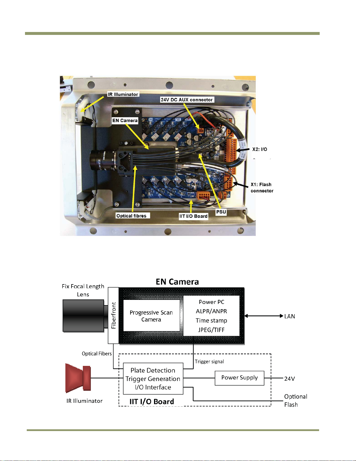
1.3 IIT Camera Overview ................................................................................. 12
1.4 Principle of Operation ............................................................................... 12
2 Preparing for installation ............................................................................ 15
2.1 Preparation for installation ......................................................................... 15
2.1.1 Over Lane Positioning ................................................................................ 15
2.1.2 Camera tilt considerations .......................................................................... 15
2.2 Performance of Trigger and Light Sensor function .............................................. 16
3 Installation ............................................................................................. 17
3.1 Camera Dimensions ................................................................................... 17
3.2 Installing the Camera ................................................................................ 18
3.2.1 Opening the Camera Housing ....................................................................... 18
3.2.2 Attaching the Safety Tether ........................................................................ 19
3.2.3 Cable Connections .................................................................................... 20
3.3 Connection to J-Panel and Power Supply ......................................................... 22
3.4 Flash .................................................................................................... 23
4 System Set-Up ......................................................................................... 24
4.1 Properties setup when using built-in Light Sensor ............................................... 25
4.2 Properties setup when using External Light Sensor ............................................. 26
4.3 Settings for built-in Automatic License Plate Reader (ALPR) .................................. 28
4.3.1 ALPR Parameters ...................................................................................... 28
4.3.2 ENSetup Image and LPR output Capture Mode ................................................... 29
4.4 Setting the IIT I/O Board internal trigger parameters .......................................... 31
5 Appendix A: Troubleshooting ....................................................................... 34
6 Appendix B: Focus Adjustment of Kowa 35mm .................................................. 35
7 Appendix C: VIS-CAM 400 IIT-2030 and VIS-CAM 400 IIT-2076 .................................. 36
8 Appendix D: Connection to TNC-100 Floodlight .................................................. 37
9 Appendix E: IIT I/O Board default settings ....................................................... 38
10 Appendix F: Quick Start Guide ...................................................................... 41
Table of Contents v
Page 6

IIT Camera System Manual
vi Table of Contents
Page 7

IIT Camera System Manual
List of Figures
Figure 1.
Figure 2. Block Diagram of the IIT Camera ................................................................... 12
Figure 3. Camera front with beamsplitter and fibers ....................................................... 13
Figure 4. The sensitive region of the picture area .......................................................... 13
Figure 5. Typical Over Lane Site Layout ...................................................................... 15
Figure 6. Typical Over Lane Site Layout Plan ................................................................ 16
Figure 7. IIT Camera Housing side view ....................................................................... 17
Figure 8. IIT Camera Housing front view ...................................................................... 17
Figure 9. IIT Camera Cable Entry .............................................................................. 20
Figure 10. Cable shield connection to chassis ................................................................. 20
Figure 11. IIT Camera I/O Board Layout ........................................................................ 21
Figure 12. IIT I/O Board Power and Data Connector X2 signals ............................................. 22
Figure 13. IIT I/O Board Flash Connector X1 signals .......................................................... 23
Figure 14. Signal Indicator LED positions ....................................................................... 24
Figure 15. Unselect the TTL Trigger input in the Trigger section for the camera. ...................... 25
Figure 16. Select Manual Control in the Camera ADR Control .............................................. 25
Figure 17. Set the value to 1.50 by manually typing the value ............................................. 26
Figure 18. Trigger Selection ...................................................................................... 26
Figure 19. Select Falling Edge in the Trigger Edge Select field ............................................ 27
Figure 20. Select Camera “ADR Control (using Light Sensor)” in the Camera ADR Control ............ 27
Figure 21. Set the Light Sensor IP address ..................................................................... 27
Figure 22. Set the value to 1.50 by manually typing the value ............................................. 28
Figure 23. Image Acquisition Image 1 ........................................................................... 28
Figure 24. Embedded ALPR section ............................................................................. 28
Figure 25. ALPR Enabled .......................................................................................... 29
Figure 26. Ethernet (EN) DATA_RDY Transmit ................................................................. 29
Figure 27. View TCP/IP ........................................................................................... 30
Figure 28. Capture Images setting .............................................................................. 30
Figure 29. Serial Communication Terminal .................................................................... 31
Figure 30. IIT I/O Board communication ....................................................................... 32
Figure 31. IIT Camera Trigger Generation Principle .......................................................... 33
Figure 32. IR Illuminator connector ............................................................................. 35
Figure 33. Kowa 35mm lens ...................................................................................... 35
Figure 34. VIS-CAM400IIT-2030 and VIS-CAM400IIT-2076 overview ......................................... 36
Figure 35. Connection to TNC-100 for VIS-CAM 400 IIT ...................................................... 37
Figure 36. Night Light Control ................................................................................... 37
VIS-CAM 350 IIT overview ............................................................................ 12
List of Figures vii
Page 8

IIT Camera System Manual
viii List of Figures
Page 9

IIT Camera System Manual
List of Tables
Table 1
Electrical Connections for the IIT Camera X2 connector ....................................... 22
List of Tables ix
Page 10

IIT Camera System Manual
x List of Tables
Page 11

IIT Camera System Manual
1 Introduction
For a Quick Start Guide, please refer to appendix G at the end of this manual.
1.1 Document Overview
This manual is a supplement to the Vehicle Imaging Subsystem 300/350/400 (VIS-CAM 300/350/400)
manual. References are made to this manual wherever applicable. This manual can be downloaded
from the JAI website.
1.2 IIT Overview.
The IIT camera is an all-in-one Intelligent Traffic Surveillance camera. The functionalities include:
1. In Image Triggering System
• Automatic detection of vehicles
• Measuring the scene light condition
• Setting up camera gain, pedestal and exposure time based on scene light condition
• Grabbing the picture
• Reading the license plate
• Transmitting the data via Ethernet or optional wireless interface
The IIT camera IR Illuminator provides sufficient illumination to produce pictures of license plates at
night time. Output for controlling an external flash is provided if total vehicle illumination is
required.
The IIT camera is based on the standard JAI Traffic Solutions EN camera platform and includes a
variety of picture formats:
1392 (H) x 1040 (V) (VIS-CAM 350 IIT)
1920 (H) x 512 (V) (VIS-CAM 400 IIT-2030)
1920 (H) x 768 (V) (VIS-CAM 400 IIT-2076)
The standard cameras are combined with an optical fiber front end for vehicle detection and light
measurement as well as a dedicated IIT I/O Board and an IR Illuminator.
Introduction 11
Page 12
1.3 IIT Camera Overview
Figure 1. VIS-CAM 350 IIT overview
IIT Camera System Manual
1.4 Principle of Operation
Figure 2. Block Diagram of the IIT Camera
12 Introduction
Page 13
IIT Camera System Manual
The concept of the IIT Camera is to exploit the retro-reflective properties of the vehicle license
plates. A retro-reflective surface returns the incoming light in the same direction it comes from.
The IIT camera is equipped with a number of emitting infrared diodes that are positioned evenly
across the camera lens. The light is frequency modulated. A beamsplitter is mounted in front of the
CCD for distribution of the incoming light to both the CCD and an array of optical fibers. The optical
fibers are connected to photodiodes on the I/O board.
Figure 3. Camera front with beamsplitter and fibers
Infrared modulated light is continuously transmitted from the camera’s IR illuminator. The reflected
signal caused by a license plate on a passing vehicle is correlated for correct modulation frequency,
phase, amplitude and the number of high samples. If the trigger criteria are validated as correct, a
trigger is generated and an image is grabbed.
The light sensor values – shutter, gain and pedestal that ensure optimal image acquisition properties
– are sampled from the reflected signal simultaneously.
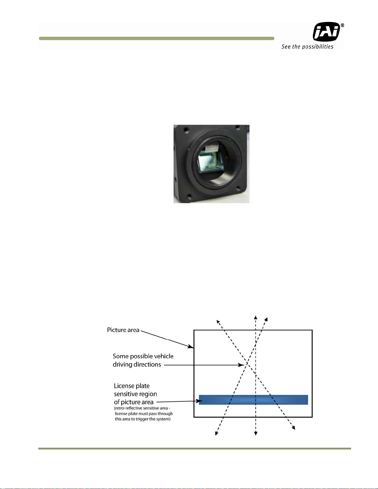
Due to the optical inverting properties of the lens, the retro-reflective sensitive part of the picture
is positioned in front of the lower part of the CCD even though the fiber array is located in the top.
Figure 4. The sensitive region of the picture area
This illustration shows the sensitive region and the way the vehicles must pass it to make the system
function.
Introduction 13
Page 14

IIT Camera System Manual
Vehicles are detected from both driving directions (front or rear shots). The system will only work
if the license plate is moving through the retro-reflective sensitive region of the picture area.
Other parts of the vehicle being retro-reflective can cause generation of triggers. These parts can
be the tail light or stickers of different kinds.
Besides the special IIT functions, many of the I/O Board functionalities from VIS-CAM 300/350/400
are available. This includes output for camera heater, output for external flash and 24V auxiliary
output.
If only the IIT trigger functionality is used (excluding the internal light sensing feature), the camera
can be mounted together with an external light sensor. For details regarding Light Sensor
positioning and configuration, please refer to VIS-CAM System Installation manual.
The J-Panel (Junction Panel) described in the VIS-CAM System Installation manual is also applicable
in conjunction with the IIT camera.
14 Introduction
Page 15

IIT Camera System Manual
2 Preparing for installation
2.1 Preparation for installation
As mentioned in the previous section is it essential for the function of the IIT Camera that the
license plate moves through the sensitive region when the vehicle passes the camera.
2.1.1 Over Lane Positioning
Over lane camera mounting is always employed when the road width being monitored contains more
than two lanes of traffic, when a convenient overhead is already in place, or when preventing
vandalism is a paramount concern.
Figure 5. Typical Over Lane Site Layout
Note: Diagram applies to both front and rear plate geometries. With any configuration, the distance
between camera and license plate must be in between 10m and 20m.
2.1.2 Camera tilt considerations
The requirement to freeze the motion of high-speed vehicles limits how steep or shallow the tilt
angle of the camera may be. For example, it is important to prevent the horizon from appearing in
the image, and thereby allowing the sun to blind the camera. For over lane installations, a camera
tilt between 20º to 30º is recommended – with 25º being considered the optimal angle. This angle of
tilt is the best compromise between minimizing visibility blockages caused by closely spaced
vehicles and maximizing plate visibility for plate mounts that are slightly recessed or tilted
downwards.
We strongly recommend not using angles outside this region as the amount of reflectance from the
license plates decreases when the angle of incident increases causing reduced performance of the
system and license plate image is distorted.
Installation Preparation 15
Page 16

IIT Camera System Manual
Figure 6. Typical Over Lane Site Layout Plan
The Light Sensor and Flash shown in Figure 6 are optional.
If over lane mounting is not possible the camera can be mounted at the side of the road as close to
the road as possible.
2.2 Performance of Trigger and Light Sensor function
As mentioned in section 2.1.1 the performance of the camera is dependent on respecting
installation parameters. These performance conditions have influence on both the trigger and the
light sensor function.
Various weather caused conditions may also influence the performance. A wet license plate has less
retro-reflectance than a dry one and the same applies if it is covered with dirt or snow. Some
license plates have reduced retro-reflectance due to wear and tear.
16 Installation Preparation
Page 17

IIT Camera System Manual
3 Installation
3.1 Camera Dimensions
Figure 7. IIT Camera Housing side view
Figure 8. IIT Camera Housing front view
Installation 17
Page 18

3.2 Installing the Camera
The camera is mounted using the same VIS Mount as VIS-CAM Systems (300/350/400). Please refer to
section 3.2 in the VIS-CAM System Installation manual for camera mount template and mounting
instructions.
3.2.1 Opening the Camera Housing
The rear plate can be removed by loosening the two screws marked “1” below. Once they are loose
they can be turned by fingers. The screws are retained by springs.
When the rear plate is removed the drawer holding the electronics can be pulled out after removing
the two screws marked “3” in figure B.
IIT Camera System Manual
The lid is held by a drawbar as shown in figure C (inside view) and figure D of the lid taken off. To
take off the lid the two screws marked “2” in figure A are loosened. Start by turning the screws 6-7
turns counterclockwise and then push them gently back in using the screwdriver. Repeat this until
the screws cannot be pushed in any more. The lid can then be taken off.
18 Installation
Page 19

IIT Camera System Manual
3.2.2 Attaching the Safety Tether
A coated wire safety tether is provided for use in attaching the removable top lid to the gantry or
pole. The tether has a loop at each end.
First you should loop the tether around the gantry and hook one loop through the other as shown in
figure A below.
Figure A
Next attach the tether to the lid using the pin on the right rear and the provided hardware as shown
in figure B.
Figure B
Installation 19
Page 20

IIT Camera System Manual
3.2.3 Cable Connections
The cable connections are the same as for VIS-CAM Systems (300/350/400) but the cable entry is
different as shown in the picture below.
Figure 9. IIT Camera Cable Entry
It is very important that the outer cable shield is connected to the rear plate at the cable entry and
that the shield around the Ethernet pairs are run to the orange terminal block as shown in the
picture.
Figure 10. Cable shield connection to chassis
20 Installation
Page 21

IIT Camera System Manual
Figure 11. IIT Camera I/O Board Layout
Installation 21
Page 22

IIT Camera System Manual
Figure 12. IIT I/O Board Power and Data Connector X2 signals
Table 1 Electrical Connections for the IIT Camera X2 connector
X2 Pin # Wire Color Signal
Remarks
1 White/Orange in Cat5E/6 cable
2 Orange in Cat5E/6 Cable
3 White/Green in Cat5E/6 Cable
4 Green in Cat5E/6 Cable Ethernet B-
5 White/Blue in Cat5E/6 Cable
6 Brown in Cat5E/6 Cable Ethernet C-
7 White/Brown in Cat5E/6 Cable
8 Brown in Cat5E/6 Cable Ethernet D-
9 Black (IN RED/BLACK PAIR) GND
10 Red (IN RED/BLACK PAIR) +24V DC
11 Pink (IN PINK/BLACK PAIR) Trigger Out+
12 Black (IN PINK/BLACK PAIR) Trigger Out -
13 Brown (IN BROWN/BLACK PAIR)
14 Black (IN BROWN/BLACK PAIR)
15 Orange (IN ORANGE/BLACK PAIR)
16 White (IN ORANGE/BLACK PAIR)
Ethernet A+
Ethernet A-
Ethernet B+
Ethernet C+
Ethernet D+
LS RS485+
LS RS485+
No Connection
No Connection
Not Used
Not Used
Not Used
Not Used
Balanced Trigger Pulse Output
Balanced Trigger Pulse Output
Serial Trigger Command Output
Serial Trigger Command Output
3.3 Connection to J-Panel and Power Supply
For connection to J-Panel please refer to VIS-CAM System Installation manual section 3.3.
22 Installation
Page 23

IIT Camera System Manual
3.4 Flash
The flash is optionally used for vehicle illumination at night. The electrical control signal connection
to the IIT camera is from X1 on the IIT I/O Board. The signals are:
Figure 13. IIT I/O Board Flash Connector X1 signals
The electrical signals are the same as the VIS-CAM Systems (350/400) flash connector and the
connections to the flash is as described in section 3.4 of the VIS-CAM System Installation manual.
Installation 23
Page 24

4 System Set-Up
The proper way of deploying the camera, as described in section 4 of the VIS-CAM System
Installation manual, also applies to the IIT Camera.
The Ethernet connection to the setup PC is accessed by removing the cable between the EN Camera
and the IIT I/O Board and connecting a RJ45 patch cable between the PC and the EN Camera. If the
PC does not have a gigabit Ethernet interface the RJ45 patch cable must be a crossover.
Note: Please do not make any adjustments of the camera mount inside the housing as this has been
adjusted from factory to the right position relative to the IR light coverage.
As a supplement the IIT I/O Board is equipped with a light emitting diode (LED) at each of the 8
fiber inputs. The LED is green when the reflected signal is detected from the fiber. When a license
plate is passing the reflection sensitive region of the scene one or more LED’s will be green. The
trigger is generated when the LED is turned off.
IIT Camera System Manual
Figure 14. Signal Indicator LED positions
24 System Set-Up
Page 25

IIT Camera System Manual
4.1 Properties setup when using built-in Light Sensor
The Camera Properties for using the built-in Light Sensor Function is shown below.
Figure 15. Unselect the TTL Trigger input in the Trigger section for the camera.
Figure 16. Select Manual Control in the Camera ADR Control
System Set-Up 25
Page 26

IIT Camera System Manual
Figure 17. Set the value to 1.50 by manually typing the value
4.2 Properties setup when using External Light Sensor
The Camera Properties for using the external Light Sensor Function is shown below.
Figure 18. Trigger Selection
Unselect the Serial Trigger input and select the TTL Trigger in the Trigger section for the camera.
26 System Set-Up
Page 27

IIT Camera System Manual
Figure 19. Select Falling Edge in the Trigger Edge Select field
Figure 20. Select Camera “ADR Control (using Light Sensor)” in the Camera ADR
Control
Figure 21. Set the Light Sensor IP address
As described in the VIS-CAM System Installation manual section 4.
System Set-Up 27
Page 28

IIT Camera System Manual
Figure 22. Set the value to 1.50 by manually typing the value
4.3 Settings for built-in Automatic License Plate Reader (ALPR)
4.3.1 ALPR Parameters
If the camera was purchased with built-in ALPR reader, the parameter set up is described below.
Figure 23. Image Acquisition Image 1
The LPR box is found by scrolling the bar on the right side all the way down.
The configuration of the built-in ALPR is found in the Properties section 9.
Figure 24. Embedded ALPR section
The field ALPR Enable must be set to “Enabled”.
28 System Set-Up
Page 29

IIT Camera System Manual
Figure 25. ALPR Enabled
The license plate character size must be set in accordance with the actual values. The character
size can be found from the EN Setup Video Window by activating the “Freeze” buttom when a
vehicle has been grabbed and then using the Measure Box to measure the height of the license plate
characters. For a TS-1335EN camera mounted with a f=25mm or f=35mm lens a suitable range could
be Minimum 15 and Maximum 45.
The Max time stopping criteria defines how much time must be used maximum for trying to read the
license plate.
The Max number of plates specifies the number of license plates the reader will be looking for. Set
to 1.
The ALPR Country Module controls which country module is used by the camera. Select Country
Module purchased.
4.3.2 ENSetup Image and LPR output Capture Mode
Select “LPR” in the ENDATA_RDY transmit field (figure 26) in camera properties window and "View>TCP/IP" in Video Window (figure 27). A pop-up window that shows the LPR output will appear after
the camera captures images of the passing vehicles.
Figure 26. Ethernet (EN) DATA_RDY Transmit
System Set-Up 29
Page 30

IIT Camera System Manual
Figure 27. View TCP/IP
In order to capture images, “Capture Images” must be selected as shown below.
Figure 28. Capture Images setting
30 System Set-Up
Page 31

IIT Camera System Manual
For more details on FTP image transfer, see section 3.2 of User’s Guide EN Camera Series
Caution: ENSetup Capture Mode and FTP Transfer Mode are exclusive to each other. Both modes
should not be enabled simultaneously in the camera.
4.4 Setting the IIT I/O Board internal trigger parameters
A number of variables can be setup in the IIT I/O Board for optimizing performance. These are
illustrated in the block diagram in figure 19: IIT Camera Trigger Generation Principle.
Commands can be launched to the board from the EN Setup application Video window by right
clicking the mouse in the left side a selecting Serial Terminal and then Laser Trigger (IIT I/O Board).
Figure 29. Serial Communication Terminal
All variables are set as hexadecimal numbers. All commands are terminated by a <CR> (carriage
return). Parameters are always two digits (01 to FF).
The commands are normally protected by a checksum that can be disabled by launching the
command #u98. The answer will be #u.
All commands are hereafter the pound key (#) followed by a capital command letter. The current
value of the variable is returned if the command is without parameter.
Example: Command #C<CR> - Answer #C32. 32hex = 50 decimal.
System Set-Up 31
Page 32

IIT Camera System Manual
Figure 30. IIT I/O Board communication
The DAC values in commands C to J are set to 32 from the factory and it is normally not necessary
to change these.
The TTL Trigger pulse width is set by command A to a value between 01 and FF (255d) times 0.1
ms. = between 0.1 and 25.5ms. Factory setting is 1ms.
The minimum time between two trigger pulses are set by command M to a value between 01 and FF
(1-255ms).
The number of consecutive samples being high from a passing license plate is set by the command
X. The factory setting is 06 and the unit is 0.2ms. The setting applies to all 8 fiber channels.
The number of consecutive samples being low between two passing license plates is set by the
command Y. Factory setting is 0A and the unit is 0.2ms.
In Appendix F is found a list of all default settings for the IIT I/O Board.
32 System Set-Up
Page 33

IIT Camera System Manual
Figure 31. IIT Camera Trigger Generation Principle
System Set-Up 33
Page 34

IIT Camera System Manual
5 Appendix A: Troubleshooting
Fault description Possible cause
1.1
1.2
Camera does not
1.3
trigger or has bad
trigger performance
1.4
1.5
2.1
Noisy pictures
2.2
Iris is not fully open
Illuminator is not properly
aligned with the camera
The supply voltage to the IIT
Camera is too low causing weak
IR illuminator
The geometry of the installation
is not in correct
Plates are not going through
reflection sensitive area
TTL and Serial trigger are both
enabled
The time between two triggers
are set too low
“Remedy”
Open Iris
See EN Camera/Illuminator
alignment procedure in Appendix C
Adjust the supply voltage to
24V±10%
See section 2 for site layout
See section 1.5
Disable TTL trigger in Properties in
EN Setup Application if IIT Light
Sensor is used
Set the minimum time between
triggers (command M) via Serial
Terminal in EN Setup application in
accordance with camera specific
values
3.1
3.2
Embedded ALPR
does not work
3.3
The license file is expired
Wrong country module has been
selected in the “ALPR country
module” in Properties field
The time is not set correctly in
the camera
Contact JAI Inc.
See section 4.3
Set the clock in the camera
correctly. The clock can be
synchronized to PC time or an NTP
server. Please refer to EN Setup
manual for details.
34 System Set-Up
Page 35

IIT Camera System Manual
6 Appendix B: Focus Adjustment of Kowa 35mm
The following describes the adjustment of the 35mm Kowa lens for best day/night performance
using IIT IR Illuminator for night illumination.
1) Disconnect IR Illuminator from IIT IO Board connector X11:
Figure 32. IR Illuminator connector
2) Start EN Setup and select repetitive trigger. Manually adjust the shutter and gain to useable
image.
3) Adjust the focus on the lens to near position :
Figure 33. Kowa 35mm lens
4) Slowly adjust the focus ring from near to far for the best picture. If the best focus position is
passed, adjust back to near and adjust towards far position again.
5) When the best position is found, secure the focus locking screw on the lens and reconnect the IR
Illuminator. Verify that the license plate focus is acceptable. The best way to check this is by
mounting an 850nm band pass filter in front of the lens.
(The license plate in the picture can be zoomed-in in the EN Setup application by holding down the
“Alt” key while dragging a box around the license plate using the mouse. The zoom mode is left by
holding down the “Alt” key and clicking anywhere in the picture)
Appendix A 35
Page 36

IIT Camera System Manual
7 Appendix C: VIS-CAM 400 IIT-2030 and VIS-CAM 400 IIT-2076
The VIS-CAM 400 IIT-2030 and VIS-CAM 400 IIT-2076 are made a little different from the VIS-CAM 350
IIT cameras. The picture below shows the VIS-CAM 400 IIT overview
Figure 34. VIS-CAM400IIT-2030 and VIS-CAM400IIT-2076 overview
Note: The TS-9725EN camera is not powered. Only fiber front is exploited. Do not adjust the
mechanical mount for this camera.
The fiber assembly in the IIT cameras is made from 8 x 1mm fibers giving a total width of 8mm. This
coverage fits the 2/3” CCD fine in the TS-9725EN and TS-1335EN (VIS-CAM350IIT) cameras having a
sensor width of 8.8mm.
The width of the sensors in the TS-2030EN and the TS-2076EN, used in VIS-CAM400, is 14.2mm and
the fiber assembly is too small to cover the width of this sensor. A solution using two cameras has
therefore been chosen where the trigger unit is a TS-9725EN camera. Only the fiber front of this
camera is exploited and the camera does not need to be powered except when alignment is
performed at factory. The TS-9725 camera is mounted with a 25mm lens and the TS-2030EN/TS2076EN with a 35mm lens giving almost the same field-of-view for the two cameras.
Having the camera and trigger unit separated this way, makes it possible to adjust the trigger-line
within the picture height, to some degree, by adjusting the camera mount inside the housing. As for
the single camera version, the camera with the fiber front, may not be adjusted. This has been
done from the factory to cover the IR illuminated area.
Please see appendix E regarding connection of floodlight for VIS-CAM 400 IIT.
Apart from the described differences, the setup and configuration is the same as the single camera
version.
36 Appendix D
Page 37

IIT Camera System Manual
8 Appendix D: Connection to TNC-100 Floodlight
The connection of TNC-100 floodlight for night time visible constant illumination is shown below.
Figure 35. Connection to TNC-100 for VIS-CAM 400 IIT
The on and off switching point are set via the camera properties in the EN Setup. The typical values
are shown below.
Figure 36. Night Light Control
Appendix E 37
Page 38

IIT Camera System Manual
50
50
50
50
50
50
50
50
01
9 Appendix E: IIT I/O Board default settings
The table below shows the default settings for microcontroller U12 on the I/O Board. The settings
are accessible from the EN Setup via Serial Communication Terminal – Laser (IIT I/O Board).
Inquiry syntax: #<command><CR>
Change value syntax: #<command><hex-value><CR>
Name CMD
Trigger pulse width A 0A 10
Dac 1 value C 32
Dac 2 value D 32
Dac 3 value E 32
Dac 4 value F 32
Dac 5 value G 32
Dac 6 value H 32
Dac 7 value I 32
Dac 8 value J 32
LS multiply factor K 01 01
LS divide factor L 01
Min time between
triggers
M C8
Hex
Value
Dec
Depends
on
model
Description
Unit 0.1ms. Sets the pulse width of the trigger
pulse output
Sets comparator level of channel 1
Sets comparator level of channel 2
Sets comparator level of channel 3
Sets comparator level of channel 4
Sets comparator level of channel 5
Sets comparator level of channel 6
Sets comparator level of channel 7
Sets comparator level of channel 8
Sets the first slope of the light sensor/ADC
curve together with LS divide factor up to the
LS knee point
See description Ks
Unit 1ms. Sets the minimum time between two
triggers. No trigger can be generated within
this time.
LS knee point P 3A 58
LS multiply 2 factor Q 03 03
LS subtract value T 96 150
Number of high
samples
Number of low
samples
X 06 06
Y 10 16
Sets the point where the lightsensor/ADC curve
changes from first slope to second slope.
Multiply factor for second slope. This factor is
multiplied by first slope to give second slope.
Offset for lightsensor/ADC curve. Below this
ADC value the light sensor value is zero.
Minimum number of successive 200μs samples
of no reflected signal before a trigger is
generated
Minimum number of successive 200 μs samples
of no reflected signal before X
38 Appendix F
Page 39

IIT Camera System Manual
r
Besides these constants there are some commands for test purposes. These are:
Name Cmd Syntax
Disable checksum u #u98<CR>
Show input vector O #O<CR>
IR Illuminator off Z #Z00<CR>
IR Illuminator on Z #Z01<CR>
Firmware version V #V<CR>
Below are the settings for the microcontroller U1 on the I/O Board. This processor controls the
camera heater, fan and power supply for the camera. The settings are accessible from the EN Setup
via Serial Communication Terminal – I/O Board.
Description
Disables checksum commands until next
power down
Shows the activated fiber channels. If
channel 2 and 3 are activated then the
answer will be #O06<CR>
Switches off the IR Illuminator
Switch on the IR Illuminator. Recycling the
power also switches the IR illuminator on.
Shows the installed firmware version for
U12
Inquiry syntax: $<command><CR>
Change value syntax: $<command><hex-value><CR>
Name Cmd
Power up
temperature high
Warning temperature
high
Fan start
temperature
Fan stop
temperature
Camera heater off
temperature
Camera heater on
temperature
Warning temperature
low
Power up
temperature low
Q 41 +65
X 3F +63
D 2D +45
K 28 +40
O F6 -10
H F1 -15
W E4 -28
T E2 -30
Hex
Value
Dec
Description
The high temperature where the power
supply for the camera is switched off
The warning temperature at which the
camera will start preparing power down
The temperature above which the fan is
switched on
The temperature below which the fan is
switched off
The temperature above which the camera
heater is switched off
The tempe
heater is switched on
The warning temperature at which the
camera will start preparing power down
The low temperature where the power
supply for the camera is switched on
ature below which the camera
Appendix F 39
Page 40

IIT Camera System Manual
Besides these constants there are some commands for test purposes. These are:
Name Cmd Syntax
Disable checksum U $u99<CR>
Firmware version V $V<CR>
Status request S $S<CR>
Description
Disables checksum commands until next
power down
Shows the installed firmware version for U1
The format of the answer is
$S<temperature><temperature status><fan
stauts><heater status><CR>
The temperature is shown in two’s
complement.
Example of an answer:
$S1A800<CR>
“1A” is 26 deg
“8” is power ok
“0” fan off, no current, no overload
“0” heater off, no current, no overload
Heater and fan status:
0: off, no current, no overload (ok)
1: on, no current, no overload (fault)
2: off, no current, no overload (fault)
3: on, no current, no overload (ok)
4: off, no current, no overload (fault)
5: on, no current, no overload (fault)
6: off, current, overload (fault)
7: on, current, overload (fault)
40 Appendix F
Page 41

IIT Camera System Manual
3
10 Appendix F: Quick Start Guide
# Description Illustration
Find a place to mount
the camera in a position
where the vehicles will
be passing through the
1
reflection sensitive part
of the picture
Sec. 1.5
Make sure that the
geometry is correct:
¾ Max height 7m
¾ Angle 20° — 30°
¾ Distance from
camera to
2
vehicle license
plate 10—20m
Sec. 2
Note: With any configuration, the distance in between camera and license plate must be 10m and 20m
Mount the camera
physically using the VIS
Mount (drill template
shown) and draw the
3
cables
Sec. 3
Connect supply voltage
wires and Ethernet to
X2 (Ethernet pairs C and
D can be omitted)
4
Sec. 3.2
Appendix G 41
Page 42

Connect the camera to
the Ethernet port of an
appropriate test PC.
Switch on the camera
5
power. Launch EN Setup
application
Sec. 4
Align camera
mechanically to correct
position by adjusting
the VIS Mount and using
the tools from EN
6
Setup. Do not adjust
the camera mount
inside the housing.
Sec. 4
Focus lens and make
sure that the lens iris is
fully open and no
polarizer is mounted.
7
Secure locking screws
after adjustment
Appendix B
Properties settings using
internal
Light Sensor:
IIT Camera System Manual
Sec. 4.1
Properties settings using
8
external
Light Sensor:
Sec 4.2
(IIT IO Board settings: X=05, Y=0A, M=C8, K=01, P=3A, Q=03, T=96)
(IIT IO Board settings: X=05, Y=0A, M=C8, A=10)
42 Appendix G
Page 43

Page 44

Europe, Middle East & Africa
Phone +45 4457 8888
Fax +45 4491 3252
Asia Pacific
Phone +81 45 440 0154
Fax +81 45 440 0166
Americas
Phone (Toll-Free) 1 800 445-5444
Phone +1 408 383-0301
www.jai.com
 Loading...