

Page 1
1
Page 2

2
WARRANTY
Limited Warranty: JAGER PRO, LLC warrants the Product to be free from malfunctions
and defects in both materials and workmanship for one (1) year from the date of purchase
(“Warranty Period”). JAGER PRO, LLC will repair or replace, at its option, the Product if
it fails to function properly during the Warranty Period, subject to the conditions and/or
limitations stated herein. Such repair or replacement is your sole remedy under this Limited
Warranty.
Limitations: Limited Warranty service will not be provided unless the Product, returned in
the manner set forth below, is accompanied by a copy of your original dated sales invoice.
JAGER PRO, LLC reserves the right to require you to provide your original dated sales
invoice. Products purchased from non-authorized dealers may not qualify for warranty
coverage.
Repair & Service: Please contact our Camera Support department at 1-706-718-9789 (EXT
3) or e-mail: [email protected] if this product requires repair or service. Troubleshooting
may be required prior to authorization for warranted repair services. If service is
recommended for your product, an RMA number and document will be provided. Additional
terms and conditions may apply. If it is determined that your product does not qualify for
warranty coverage, the following charges may or may not apply: Labor Hours, Parts,
Materials, Estimate Services, Shipping and Handling.
This Limited Warranty does not cover the following:
a. any defect in or damage to the Product that occurs due to mishandling of the Product;
b. any defect in or damage to the Product that occurs due to repair, modication, or other
similar activity after your purchase of the Product;
c. any defect in or damage to the Product that occurs due to the transport, dropping, shock,
or other similar activity after your purchase of the Product;
d. any defect in or damage to the Product that occurs due to careless or improper storage,
or improper use or maintenance of the Product;
e. any defect in or damage to the Product that occurs due to foreign objects such as dirt or
grime, sand, water or liquids entering the inside of the Product; and
f. any defect to the Product related to your failure to follow proper operating instructions
provided by JAGER PRO, LLC, claims made after the Warranty Period, or your failure to
follow the instructions set forth below with respect to return of the Product to JAGER PRO,
LLC.
All other express and implied warranties for the product, including the implied warranties of
merchantability and tness for a particular purpose are hereby disclaimed. JAGER PRO,
LLC expressly disclaims all warranties not stated in this warranty. Any implied warranties
that may be imposed by law are limited in duration to the terms of this express limited
warranty. Some jurisdictions do not allow the exclusion of implied warranties or limitations
on how long an implied warranty lasts, so the above exclusions or limitations may not
apply to you. In no event will JAGER PRO, LLC be liable to you, or any third party, for any
damages in excess of the purchase price of the product. In addition, JAGER PRO,LLC shall
in no event be liable to you, or any third party, for any direct or indirect damages or other
special, incidental, exemplary or consequential damages arising out of the use or inability to
use the product. Some jurisdictions do not allow the exclusion or limitation of incidental or
consequential damages for some products, so the exclusions or limitations may not apply to
you. This limited warranty gives you specic legal rights, and you may also have other rights
which may vary from jurisdiction to jurisdiction.
Notwithstanding any terms of this Limited Warranty to the contrary, no warranty coverage
shall be provided for a Product purchased from, through, or with the assistance or
involvement of any Internet auction web site. JAGER PRO, LLC reserves the right to modify
its warranties prospectively at any time, in its sole discretion.
Page 3
3
TABLE OF CONTENTS
Camera Characteristics................................................ 04
Quick Start Programming............................................. 07
Main Menu Tabs............................................................ 08
Camera Tab.................................................................. 09
Trigger Tab.................................................................... 10
System Tab................................................................... 11
Wireless Tab................................................................. 12
Manually Sending Photos............................................. 15
SMS Command Codes................................................. 16
LOGIN Fail Corrective Action........................................ 17
Timing Camera Transmitter to Control Box Receiver.... 18
Camera Deployment..................................................... 19
Care and Maintenance................................................. 21
Accessories.................................................................. 22
Purchasing a SIM Card................................................. 23
Replenishing a SIM Card.............................................. 23
Glossary........................................................................ 24
SMS Command Code List............................................ 25
Page 4
4
Front View
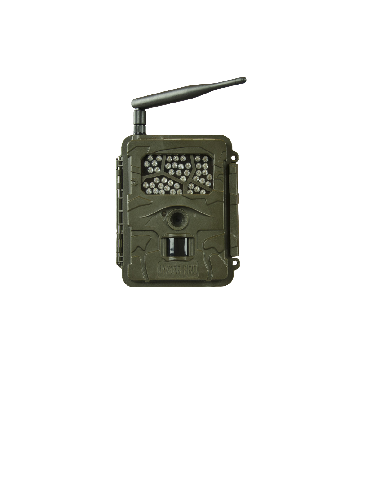
1
2
3
4
5
6
CAMERA CHARACTERISTICS
1. Antenna: Standard antenna shown receives cell tower signals. Our 5
decibel booster antenna is available as an accessory for operation in low
signal areas.
2. IR Illuminator: 44 infrared LEDs that illuminate the target area when
camera functions at night.
3. Camera Lens: The camera lens has a 52 degree eld of view with no
magnication. This enables users to observe a 20’ eld of view measured 15’
from the lens and a 32’ eld of view when measured 21’ from the lens.
4. PIR Sensor: Passive Infrared motion detector. Senses the presence of
a moving object which triggers the camera to take a photo or record a video.
5. Ambient Light Sensor: Detects surrounding light to automatically
control day and night camera functions. This sensor also emits a red,
blinking LED when the selector switch is moved to SETUP. The LED will
stop blinking within 10 seconds after the selector switch is moved from
SETUP to ON indicating the camera is operational and active.
6. Locking Latch: Secures the camera front housing to the main body
housing while providing a waterproof seal to internal components.
This manual is intended to visually guide users through the individual steps
to properly program, operate and maintain the 3G GSM version of our
JAGER PRO M.I.N.E™ and I.C.E.™ Cameras.
Page 5
5
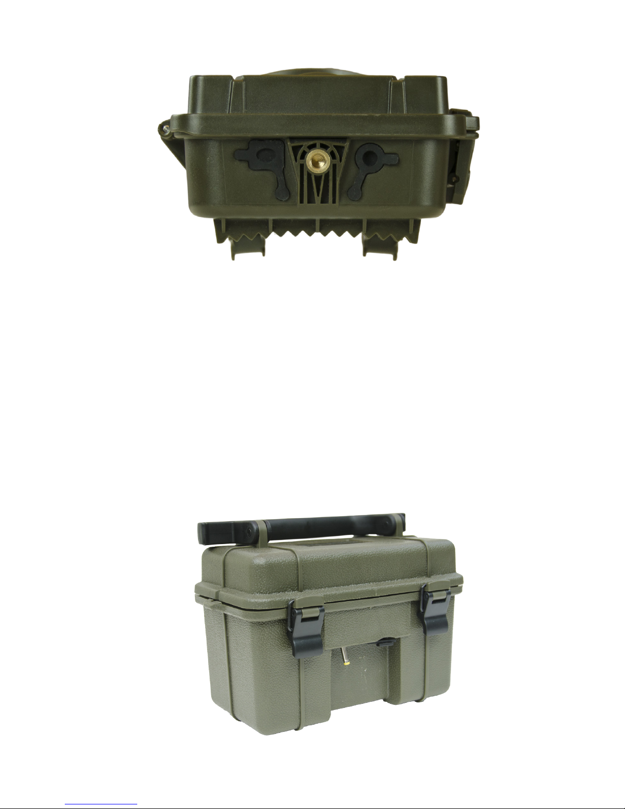
1. DC Port Plug: Waterproof seal to protect internal components when
external battery (optional equipment) is not in use.
2. Mounting Port: 1/4 x 20 internal threads for securing camera to a
T-Post mount. Only thread external devices two complete rotations into the
camera mounting port then tighten using the mount’s adjusting nut. Forcing
external threads to the bottom will damage mounting port and camera
housing.
3. USB Port Plug: Waterproof seal to protect internal components when
USB cable is not in use.
Bottom Outside View
1
2 3
1
6v DC External Battery
Page 6
6
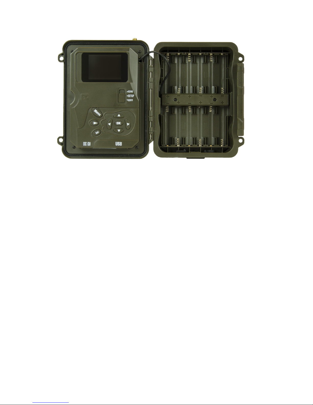
Inside View
1. Antenna Port: Attachment point to install various antennas depending
on local cellular strength. Our 5 db booster antenna is available as an
accessory for operation in low signal areas.
2. Display: Screen to observe menus, photos and settings.
3. Selector Switch: Used to enter into any of the three operating modes:
OFF, SETUP and ON.
4. Menu Button: Used to select various camera options.
5. Move Left Button: Moves from the highlighted area to a selection left.
6. Move Up Button: Moves from the highlighted area to a selection
above.
7. Move Right Button: Moves from the highlighted area to a selection
right.
8. Move Down Button: Moves from the highlighted area to a selection
below.
9. OK Button: Selects the highlighted item.
10. DC Port: 6 volt connection for external battery optional battery pack.
11. USB Port: Standard USB cable connection interface to transfer
information between the camera and a computer.
12. Battery Polarity Symbols: Located on the front of the battery tray.
Aids in 12 proper battery polarity and installation.
13. Playback Button: Allows user to view pictures on SD card.
14. Del Button: Deletes unwanted pictures, numbers, and letters.
7
3
4
2
6
589
1
10 11
12
13
14
Page 7
7
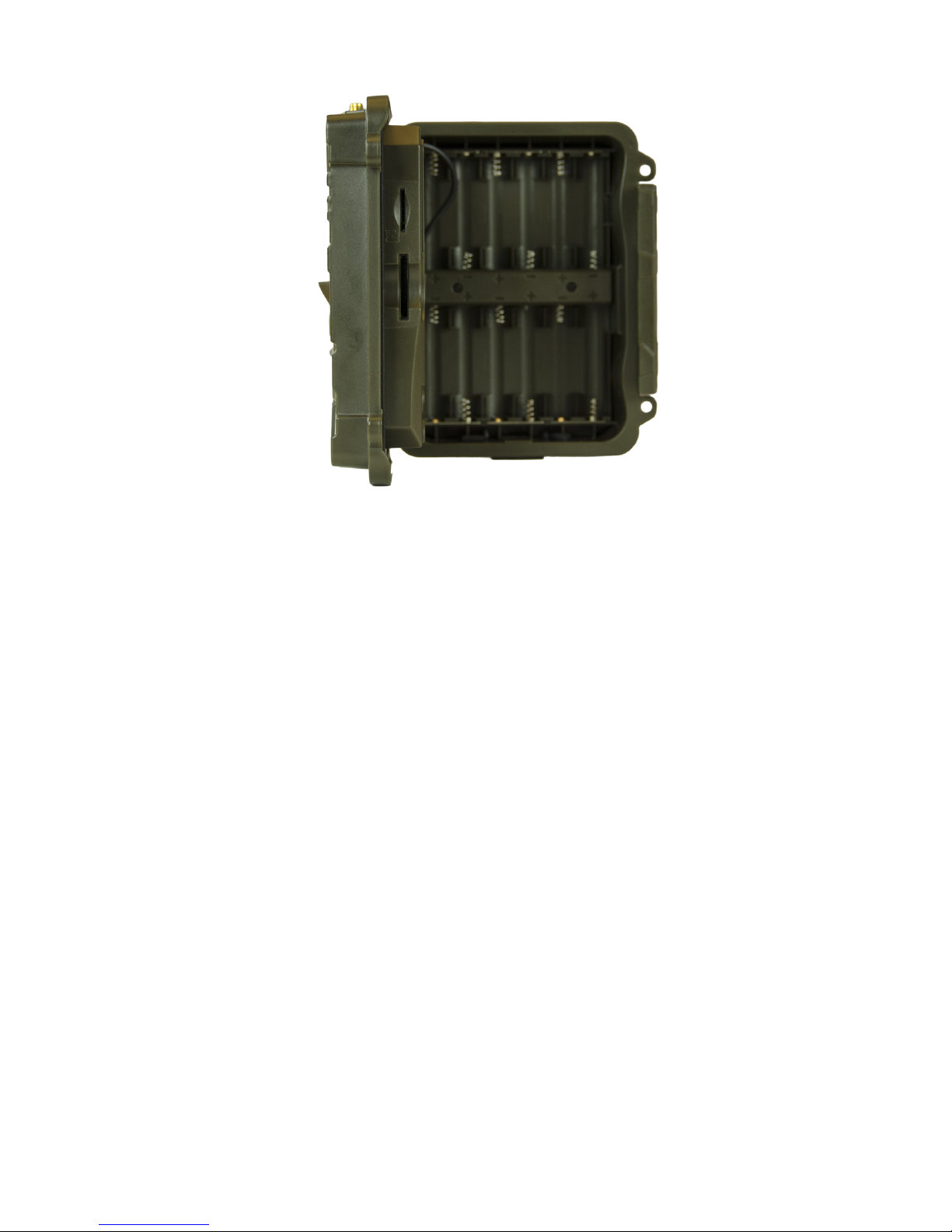
Left Side View
1
2
1. SIM Card Port: Slot for receiving a cellular SIM card from GSM network
providers such as AT&T and T-Mobile.
2. SD Card Port: Slot for receiving an SD card. The camera has no
internal memory. An SD card smaller than 32GB must be used to store
photos, video and GSM data.
QUICK START PROGRAMMING
Begin programming the M.I.N.E™ Camera for operation by removing the
protective cap and installing the standard antenna onto the antenna jack.
Ensure the black rubber O-ring is not removed from the antenna jack
threads. Twist the antenna base snug but do not over tighten.
Unlock the full length locking latch to access the main body. Follow the
battery polarity symbols located on the front of the battery tray to properly
install 12 each batteries. We only recommend Energizer brand AA Lithium
batteries for the best performance in the eld. Alkaline or rechargeable AA
batteries will not operate high-tech equipment nearly as long.
The camera will function in emergency situations using only four AA Lithium
batteries in the two left columns. We recommend our 6 volt external power
supply for extended, long-term camera use in the eld. AA Lithium batteries
are still required for initial start-up until the camera housing is closed and the
6 volt external power supply cable is inserted into the camera battery port.
Insert an activated SIM card into the SIM card port with the notch located in
the top right-hand corner. A formatted SD card must be used for the camera
to function. Move the selector switch from OFF to SETUP. The camera will
Page 8
8
MAIN MENU TABS
Press the MENU button to access the program display. The camera will
shut down after 3 minutes sitting idle to conserve battery power. Users must
move the selector switch to OFF then SETUP again to restart the camera
and access MENU.
Press the MENU button to access the program display. There are four main
menu tabs; CAMERA, TRIGGER, SYSTEM and WIRELESS. Press the
left or right buttons to change tabs. Press the up or down buttons to cycle
through the submenu settings of the highlighted green tab. Press left or right
to select items with green highlights to edit and view choices.
Press OK to save the new setting. Press up or down to view the next setting.
Press MENU and return to the top of the MENU tab before able to move left
or right to view or change another highlighted tab.
X
immediately power OFF after the logo is displayed.
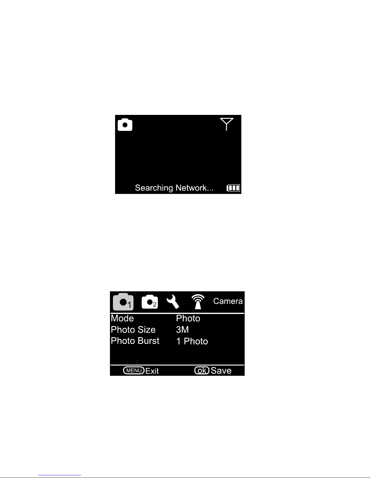
The camera supports up to a 32 GB SD card. Ensure the SD card is not
locked and insert it into the SD card port. Move the selector switch from OFF
to SETUP. The screen will display “Searching Network” at the bottom center
of the screen. It usually takes 20 to 30 seconds for the camera to nd the
network. AT&T or T-Mobile will appear in the top center of the screen after
connecting to the network and the signal strength symbol will appear in the
top right.
Page 9
9
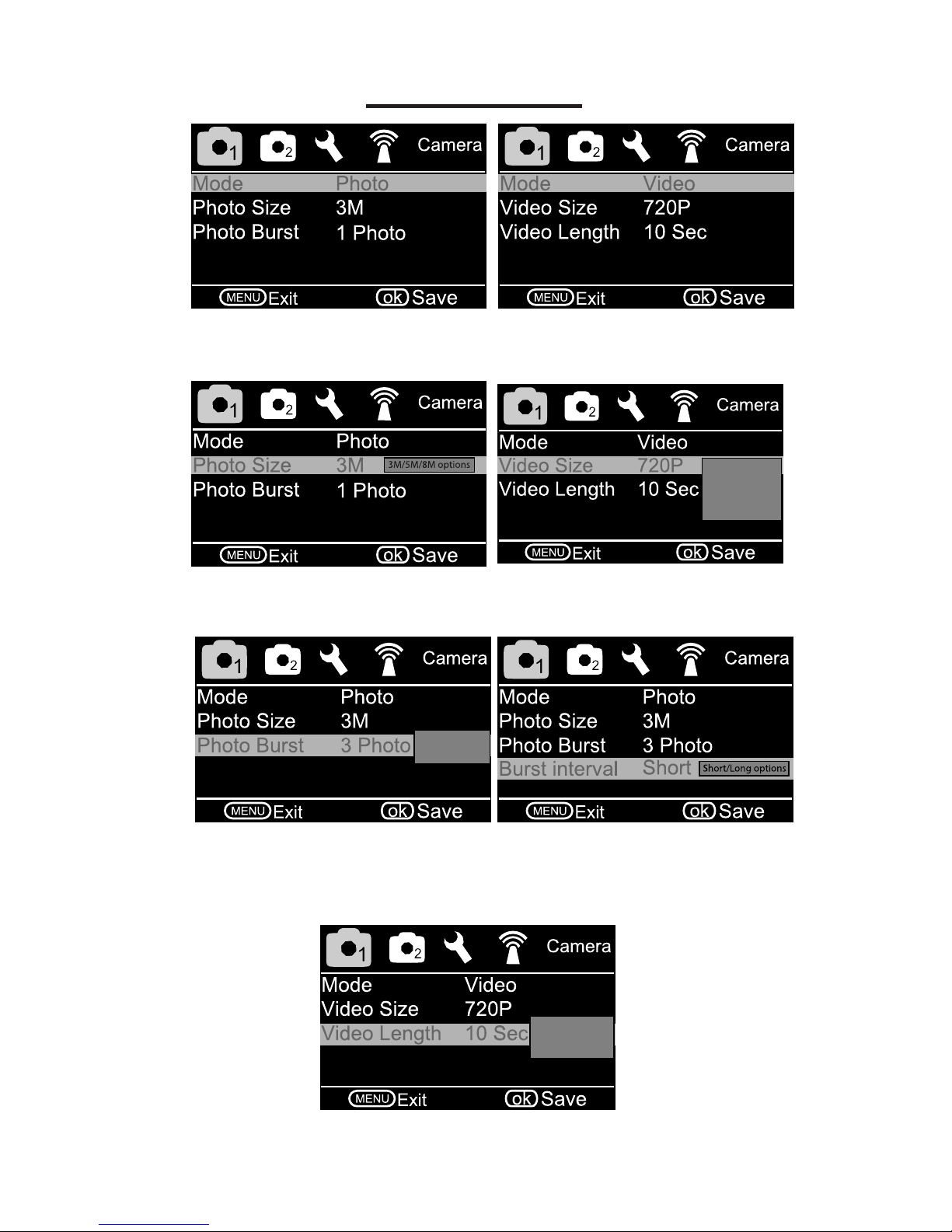
Camera Tab:
• Mode: Choose Photo or Video. (Recommend Photo for immediate text
information sent to phone.)
720p/WVGA
QVGA/1080p
options
• Photo Size: Choose the image size; 3MP, 5MP, or 8MP.
• Video Size: Choose the video size.
1/2/3 burst
option
• Photo Burst: Choose the number of pictures taken consecutively after
each triggering. (Recommend 1 Photo)
• Burst Interval: Choose between one or half second delay between
pictures.
1-30 sec video
length options
• Video Length: Choose how long the video will be in size between 1 and
30 seconds.
Page 10
10
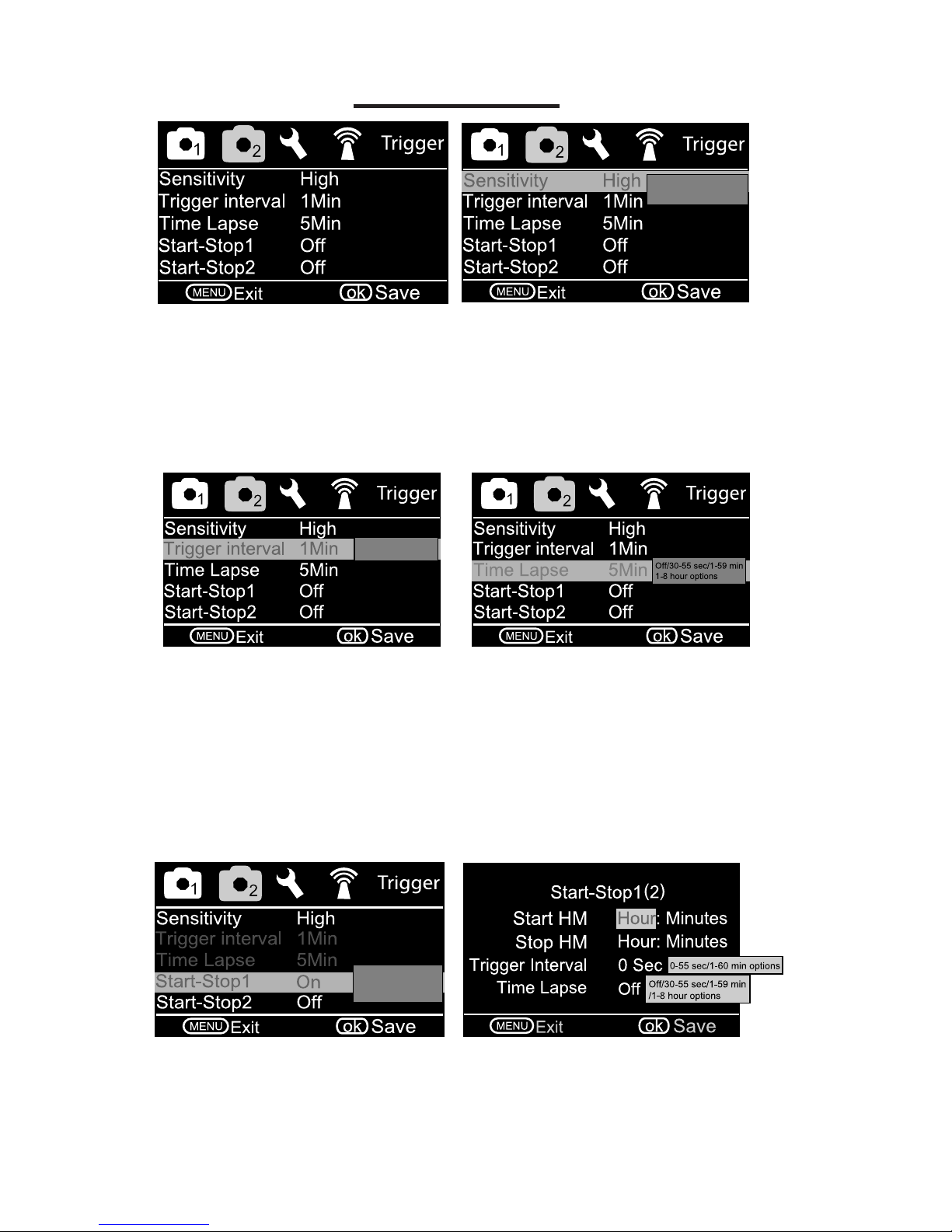
• Trigger Interval- The timeout period between PIR triggers for each
photo or video capture. We recommend a two minute trigger interval. A
one minute selection may not allow a photo to transmit via SMS in low signal
areas before the next PIR trigger. The photo is always saved on the SD card
but may not have time to send via SMS to your phone or email.
• Time Lapse
OFF: Camera triggers only during PIR event. (Recommend)
ON: Camera automatically triggers at selected intervals.
Trigger Tab:
• Sensitivity- Passive Infrared (PIR) Trigger Sensitivity
High: The most sensitive setting and will trigger camera operation when
any movement is detected.
Low: The least sensitive setting used when foliage, wind or shadows
trigger excessive photos.
Normal: Average sensitivity. (Recommended)
0-59 sec or1-60 min
option
Trigger interval and
Time Lapse disabled
when on
• Start - Stop
OFF: Camera triggers 24 hours per day.
ON: Camera only triggers between the START and STOP times
programmed. Could be used to avoid high trafc from non-target species
during specied times.
Off/High/Normal
Low options
Page 11
11
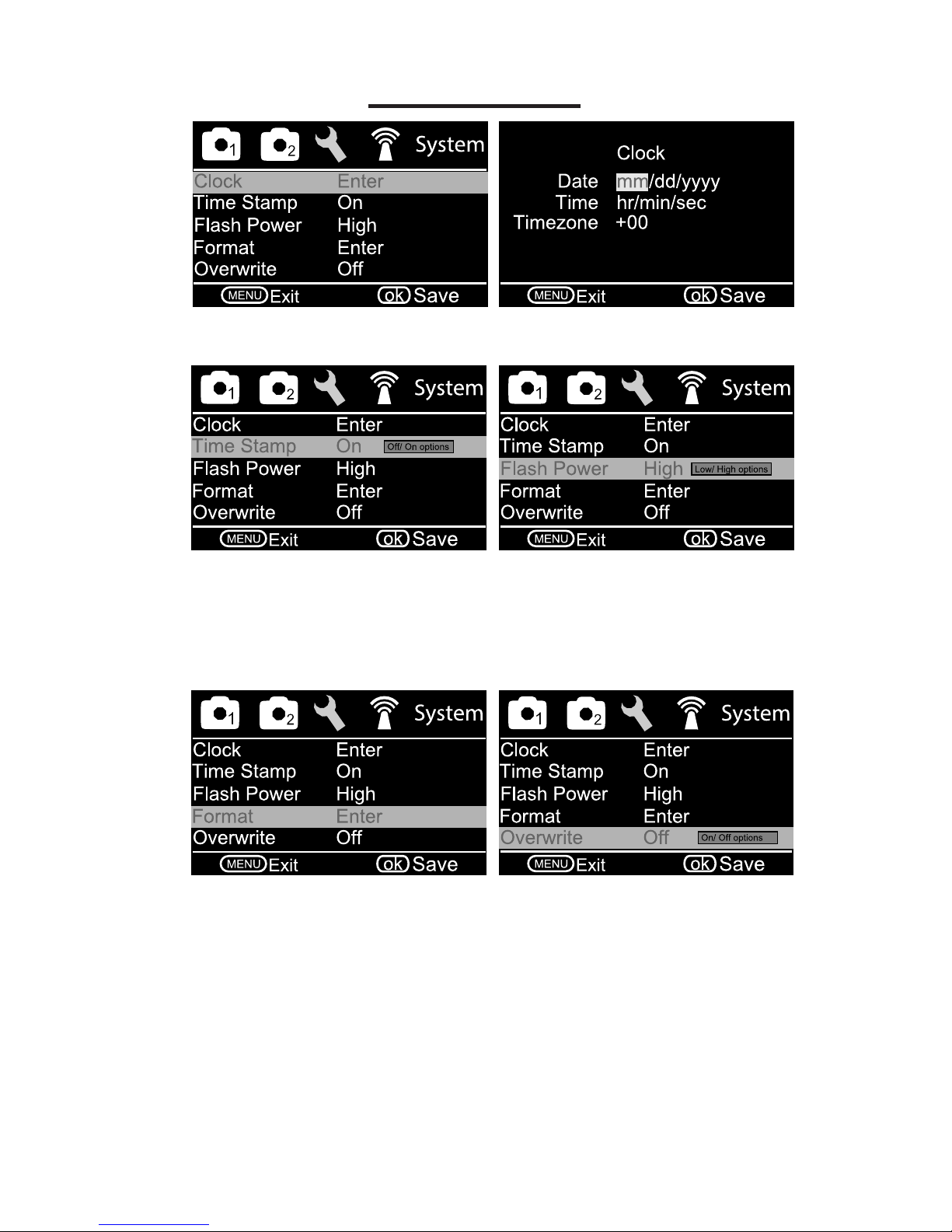
System Tab:
• Set Clock: Enter correct Date and Time.
• Time Stamp: Choose ON or OFF to select the date and time stamp on
the picture.
• Flash Power: Choose between Low or High. We recommend High to
extend infrared illumination beyond trap.
• Format: Formats the SD card and deletes all photos/videos.
• Overwrite
OFF: (Recommended) Retains saved photos and videos on SD card
when full.
ON: Camera deletes the oldest photos/videos from SD card when full and
continues to save newer photos/videos.
Page 12
12
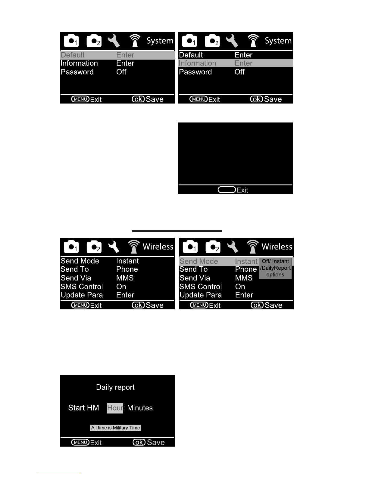
• Default: Restores camera back to factory settings.
Wireless Tab:
• Send Mode
Instant: (Recommended) The camera sends a photo immediately
when it takes a photo. It will only send an SMS text message of the
sequence number when a video is taken (Video: 3/99). The Max Num eld
indicates the maximum number of photos or texts allowed to be sent within
24 hours. The camera resets to zero each night at 0000 hours.
Daily Report: Sends an SMS to
tell how many photos and videos
were captured during the past 24
hours. In picture mode, the SMS tells
the accumulated picture quantity
together with the latest captured
picture. In video mode, the SMS tells
the accumulated video quantity only.
• Password: The default password is 0000. Choose OFF to stop this
function and ON to set a four digit password.
• Information: Displays rmware
version of camera and IMEI number.
Check our website for the latest
rmware version and uploading
instructions.
MENU
Module S150
HW Ver 52
FW Ver 2014/09/18-18:32:52
IMEI 012813002148916
Page 13
13
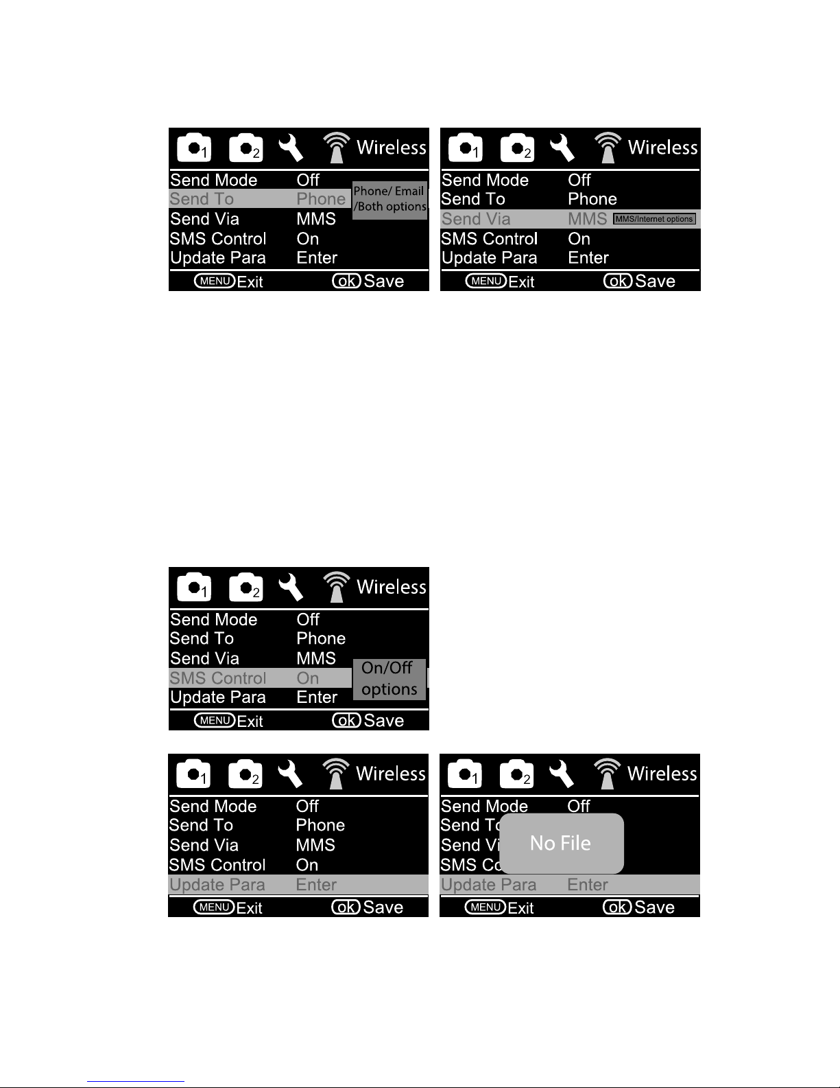
• Send To:
Phone: (Recommended) A text photo will arrive to a cell phone much
faster than an email can arrive to either a cell phone or computer provided
the cell phone has good reception. A phone number must appear in
Recipients.
Email: The image will be sent to email. An email address must appear in
Recipients.
Both: The image will be sent to both a cell phone and an email address. A
cell phone number and an email address must appear in Recipients.
• Send Via
MMS: (Recommended) Image sent by text message.
Internet: Image sent by internet using a data plan.
Off: GSM function is de-activated. Photos and videos will not be sent to a
recipient but will be saved to the SD card.
• SMS Switch: The SMS Switch
must be ON for the camera to
receive text commands from four
listed phone numbers.
• Update Para: Replaces parameters from another camera. Not
necessary for daily operation.
Page 14
14
Image From On
MENU
ok
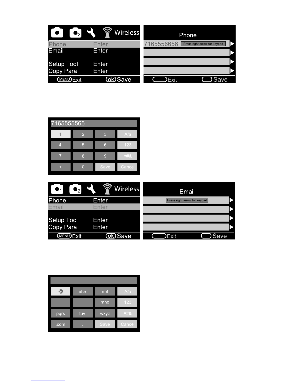
• Phone: Press OK to select an open tab and move right one click to
input the recipient phone number. Use the keypad to type the 10-digit
phone number. Select SAVE which returns to the Phone submenu.
Select SAVE which returns to the WIRELESS submenu.
Press the delete button to erase
each of the number characters.
Use the arrow buttons to select the
numbers. Select save to return to
menu.
MENU
ok
• Email: Press OK to select an open tab and move right one click to
input the recipient email address. Use the keypad to type the email
address. Select SAVE which returns to the Email submenu. Select
SAVE which returns to the WIRELESS submenu.
ghi jkl
Press the delete button to erase
each of the existing email address
characters. Use the arrow buttons to
select the characters and numbers.
Select save to return to menu.
Image From On
Page 15
15
Image From On
ghi jkl
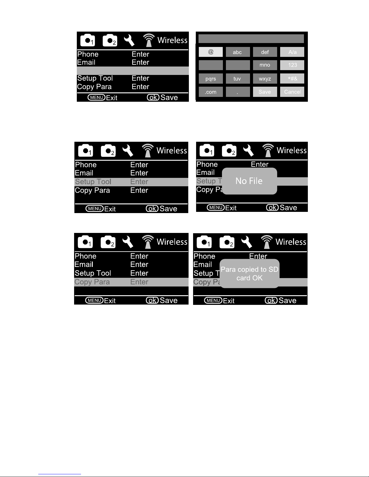
Image From: Press OK to select ON and input the camera, trap or bait site
name. Use the keypad to type the information. Select SAVE and return to the
WIRELESS submenu.
Copy Para: Will not be used for normal daily operations.
Setup Tool: Will not be used for normal daily operations.
MANUALLY SENDING PHOTO
Our 3G camera is designed to test program settings and SIM card service
by manually sending a photo. Move the selector switch from OFF to SETUP.
Allow the camera 30 seconds to search the wireless 3G network. AT&T will
appear in the top center of the LCD screen after connecting. Pressing the
OK button will immediately capture a photo and upload the image to the
network by following the camera program settings.
The automatic commands displayed in the bottom center of the LCD screen
If you have any questions, refer to the JAGER PRO™ M.I.N.E. & I.C.E.
(3G) Camera Operations Video at 04:20 MAIN MENU TABS for more
information.
Page 16

16
The SMS Switch must be ON for the camera to receive text commands and
was previously covered under the WIRELESS menu tab. The M.I.N.E™
Cam is able to receive text commands from up to four phone numbers to
perform 22 different functions remotely. All four phone numbers have the
ability to send and receive SMS commands to control the camera.
We store camera SIM card numbers into our cell phones by trap number.
These are the most frequently used functions. The code to check Cellular
Signal Strength is *150#. The response from the camera is “The signal
is good.” A response of “The signal is weak” or “The signal is very weak”
indicates a 5 decibel booster antenna on a telescoping pole is needed.
The code to check Battery Level is *201#. The response from the camera is
“Battery level 5” indicating a full charge. The camera will stop functioning at
“Battery level 1.”
The camera cannot text video; only photos. The code to change camera
mode to photo is *200#0#. The response from the camera is “Set to photo
mode”.
The code to close the M.I.N.E.™ Gate or Activate the RF Trigger is *777#.
The response from the camera is “RF triggered”. This code is only a function
of the M.I.N.E.™ Camera. The I.C.E.™ Camera does not utilize an internal
transmitter.
After the M.I.N.E.™ Gate has been closed, the camera will continue sending
photos from the increased motion at the trap enclosure. The code to turn
the Send Mode Off is *140#2#. The response from the camera is “Send off”.
Photos will continue to be triggered and saved to the SD card unless the PIR
sensitivity is turned “OFF”.
Future photos will not be sent until the Send Mode is returned to instant. The
code to change the Send Mode to Instant is *140#0#. The response from the
camera is “Send instant photo”.
The command to add a new recipient phone number of 706-555-1212 is
*100#7065551212#. The response from the camera is “Phone number
added”. Refer to page 25 of this operations manual for all 22 available SMS
codes.
SMS COMMAND CODES
If you have any questions, refer to the JAGER PRO™ M.I.N.E. & I.C.E. (3G)
Camera Operations Video at 13:47 SMS COMMAND CODES for more
information.
If you have any questions, refer to the JAGER PRO™ M.I.N.E. & I.C.E. (3G)
Camera Operations Video at 12:45 MANUALLY SENDING PHOTO for
more information.
are rst “Setting”, then “Uploading”, then “Sending” followed by “Sent”. This
process should take approximately 20 seconds to upload and send the photo
from the camera and another 10 seconds to receive the photo as an SMS
text to a programmed phone when the 3G signal is strong.
Page 17
17
LOGIN FAIL CORRECTIVE ACTION
X
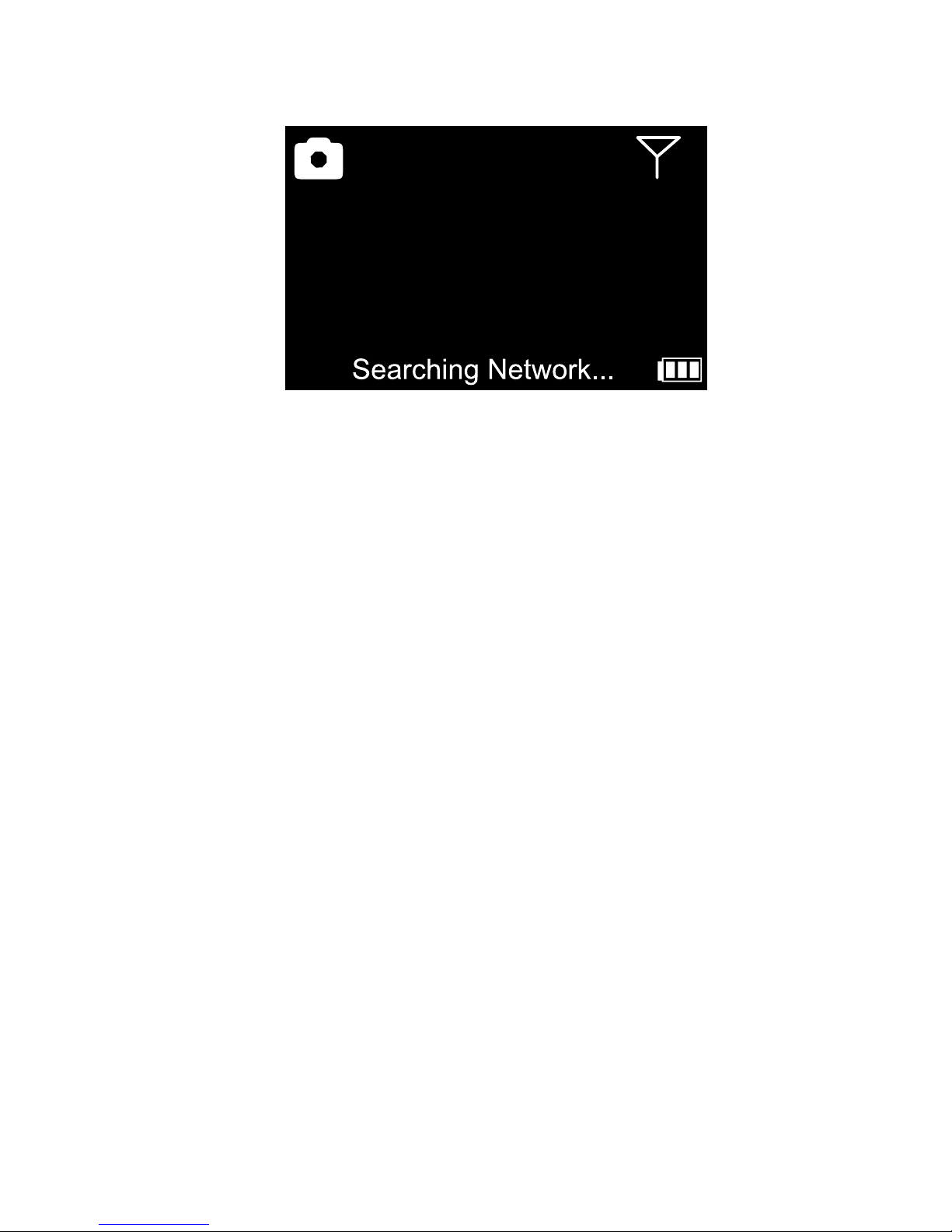
Users should always test their camera at a new location prior to erecting a
feeder or a trap enclosure. Move the selector switch from OFF to SETUP.
The screen will display “Checking Network”. Allow approximately 20 to 30
seconds for the camera to acquire a cellular signal. If the camera does not
automatically connect to the cellular network within 60 seconds, the standard
antenna is not sufcient at this location and the camera will be unable to
send texts and photos via MMS. Our ve decibel booster antenna mounted
to a 16 foot long telescoping antenna will be necessary for remote cellular
operation in low signal areas.
Drive a 7 foot long T post into the ground approximately 12 inches to the
right and rear of the camera post. Attach our booster antenna with mount to
a 16 foot long telescoping pole using U-bolts or zip ties. Secure the antenna
cable to the telescoping pole in multiple locations to eliminate cable noise
from wind.
Remove the standard antenna. Carefully thread the booster antenna cable
to the antenna port and tighten. Slide the rubber waterproof boot over the
booster antenna cable connector.
If you have any questions, refer to the JAGER PRO™ M.I.N.E. & I.C.E. (3G)
Camera Operations Video at 17:13 LOGIN FAIL CORRECTIVE ACTION
for more information.
Page 18
18
TIMING CAMERA TRANSMITTER TO
CONTROL BOX RECEIVER
THIS STEP IS ONLY A FUNCTION OF THE 3G M.I.N.E.™
CAMERA. THE 3G I.C.E.™ CAMERA DOES NOT UTILIZE AN
INTERNAL TRANSMITTER.
The 3G M.I.N.E. Camera has an internal transmitter on the circuit board and
must be located within 50 meters of the M.I.N.E.™ Gate to operate correctly.
Users must manually calibrate the camera transmitter signal to each control
box receiver the rst time they are paired together. One camera will operate
multiple control box receivers to trigger multiple gates simultaneously at a
trap enclosure.
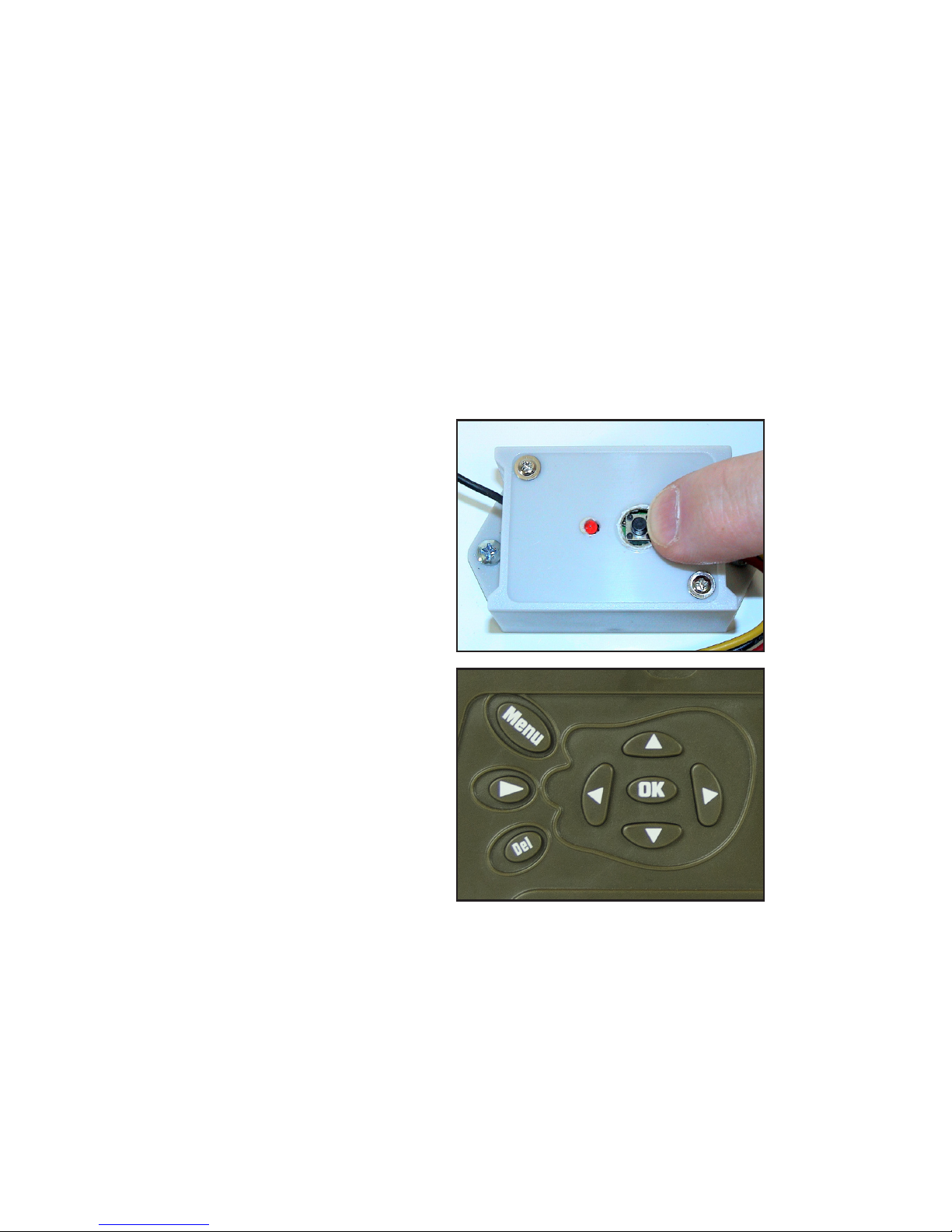
1. Move camera selector switch from OFF to SETUP.
2. Open control box housing and
press (A) receiver button. The
receiver red light will only emit for 10
to 15 seconds.
3. Press the camera (A) left arrow
and release then press the camera
(B) right arrow and release to send
a manual RF signal to the control
box. The receiver light should ash
three times and shut off if performed
correctly. Conduct a test by repeating
this step, the latch will activate.
Repeat these steps on other control box receivers if multiple gates are used
at the trap enclosure. Move camera selector switch from SETUP to ON and
send SMS text command *777# to test transmitter and receiver calibration
and gate operation.
A B
A
If you have any questions, refer to the JAGER PRO™ M.I.N.E. & I.C.E. (3G)
Camera Operations Video at 18:41 TIMING CAMERA TRANSMITTER TO
CONTROL BOX RECEIVER for more information.
Page 19

19
CAMERA DEPLOYMENT
Align the 1/4 by 20 threads of the T-Post mounting bracket to the camera
mounting port. Thread the mounting bracket no more than three complete
rotations into the camera mounting port. Then tighten using the adjusting
nut. Forcing external threads to the bottom will damage the camera
mounting port and the camera housing.
Never mount the M.I.N.E.™ Cam on the same T post securing a trap
panel or severe damage may result. Always mount the M.I.N.E.™ Cam
on a separate 8 foot long T post at least 12 to 24 inches outside the trap
enclosure. Lower the square collar at a diagonal over the T post spine
and studs, then lower into position between two studs. Insert the mounting
wedge between the T post spine and square collar. Install the thumbscrew
into the 1/4 by 20 threads on the mounting wedge. Tighten the thumbscrew
against the T post spine to secure the camera mount.
Users are able to receive a wider eld of view by mounting the camera at a
higher elevation. Lower the square collar at a diagonal over the T post spine
and studs, then lower into position between two studs. Insert the mounting
wedge between the T post spine and square collar. Install the thumbscrew
into the 1/4 by 20 threads on the mounting wedge. Tighten the thumbscrew
against the T post spine to secure the camera mount.
When mounting using the higher elevation method, it is easier to attach the
booster antenna (if needed) to the camera while on the ground. Remove
the standard antenna from the camera’s antenna port. Carefully thread the
booster antenna cable to the antenna port and tighten. Slide the rubber
waterproof boot over the booster antenna cable connector.
Drive a second 7 foot long T post into the ground approximately 12 inches
to the right and rear of the camera T post to attach the antenna pole. Secure
the 8 foot long T post with camera to the 7 foot long T post using zip ties.
The higher camera elevation will allow the booster antenna to exceed 20 feet
by elevating and securing the telescoping pole to the T post with zip ties.
Standing on a step ladder, align the M.I.N.E.™ Cam by loosening the ball
head set screw and centering the camera’s view to the ground beneath the
feeder legs. Tighten the ball head set screw to secure the camera’s position.
Move the selector switch from OFF to SETUP. The screen will display
“Searching Network”. The camera has successfully acquired a cellular signal
when the service provider’s initials appear on the display. Move the selector
switch from SETUP to ON. Close and latch the camera within 10 seconds
before the Ambient Light Sensor LED stops blinking green and the PIR
triggers a photo. The M.I.N.E.™ Cam is now operational and active.
Secure the 6 volt external power supply to the camera mount with the battery
bracket. Open the camera DC external battery port and insert the battery
cable plug into the camera for extended, long-term operation.
Page 20
20
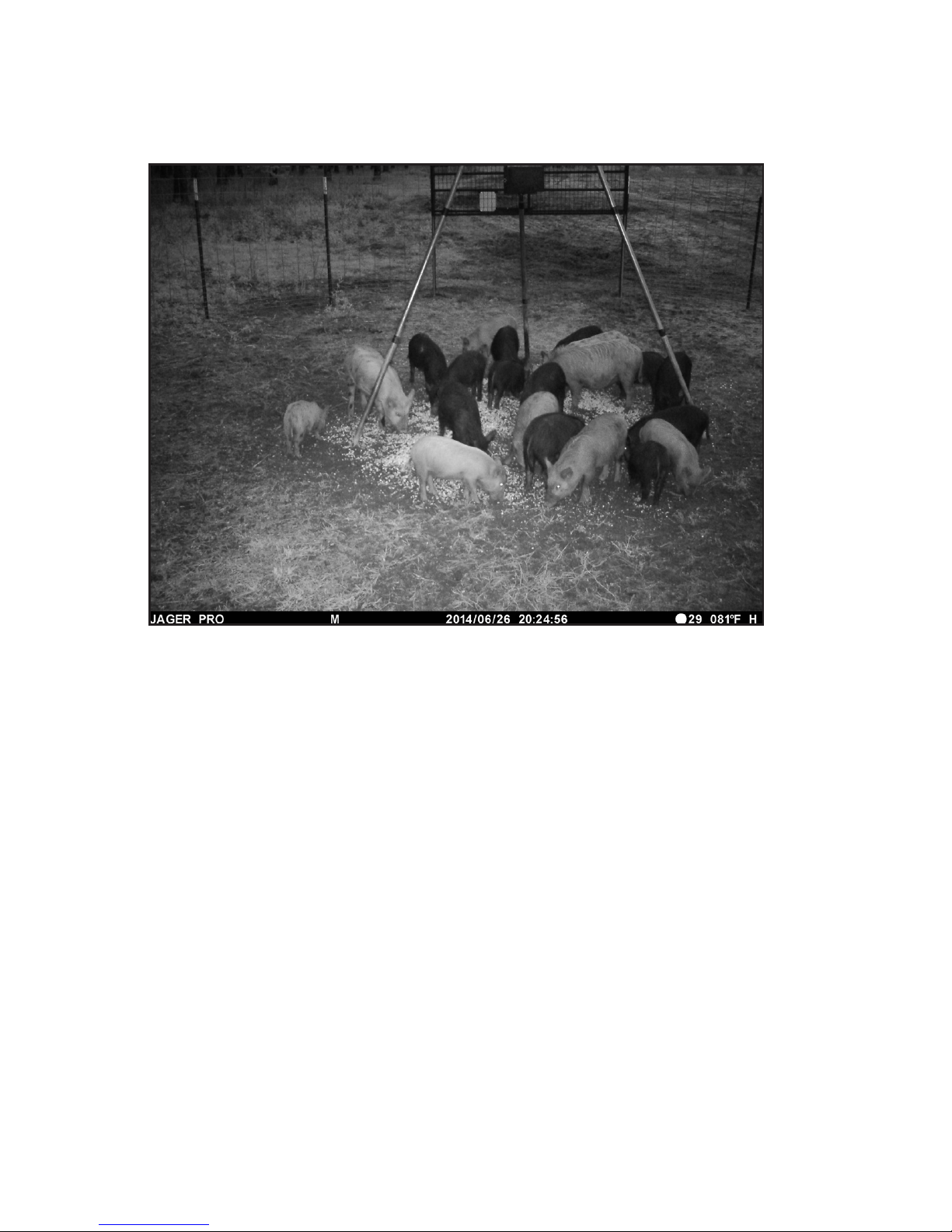
Ensure the camera PIR triggers and sends a photo to your cell phone. This
step will verify the camera is positioned and programmed correctly. Ensure
the feeder is centered and the entire gate opening is visible.
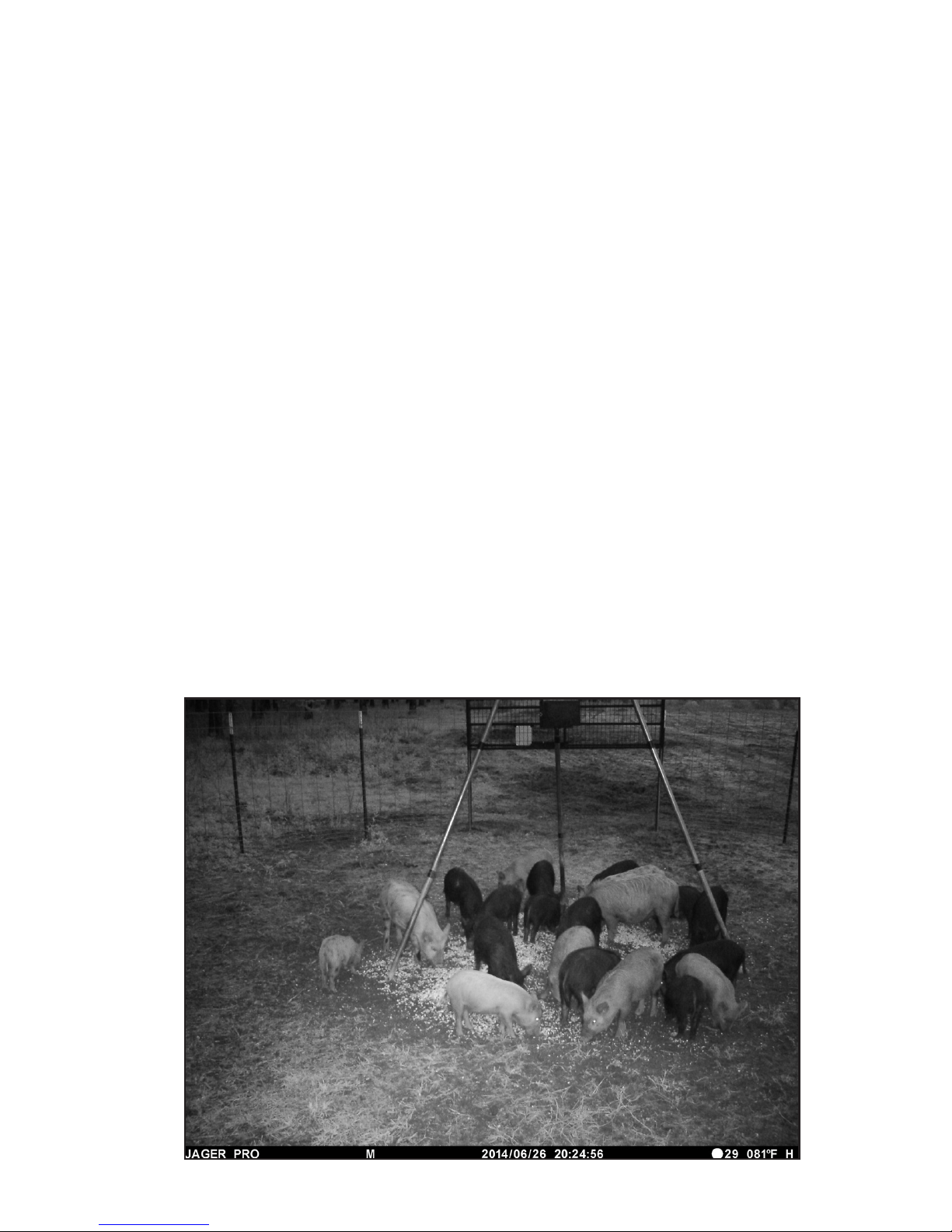
From left to right- JAGER PRO is the camera manufacturer. The “M”
indicates the photo was triggered by “Motion”. The letter “S” would indicate
a photo triggered by SMS code *500#. “P” would indicate a photo triggered
by “Time Lapse” and “E” would indicate a manually triggered photo using the
camera’s OK select button during SETUP.
The date is 26 JUNE 2014. The time is 2024 or 8:24 in the evening. It is a
new moon with 29 more nights until the next new moon. The temperature
is 81 degrees Fahrenheit. The battery symbol is “H” which indicates the
batteries are at a high charge.
The nal step is to register your new equipment on the JAGER PRO website
via the camera IMEI number so we may provide appropriate rmware
updates. These updates are necessary to ensure your equipment operates
efciently as network wireless technology changes. Multiple cameras
and control boxes may be registered on a single submission by following
directions in your Quick Start Guide.
If you have any questions, refer to the JAGER PRO™ M.I.N.E. & I.C.E. (3G)
Camera Operations Video at 20:08 CAMERA DEPLOYMENT for more
information.
Page 21
21
WARNING! The DC Port plug must be removed before accessing
camera functions. Opening the camera while the external battery is
plugged into the housing port may result in damage to both the camera
and the external battery.
WARNING! Removing screws from internal camera ports will damage
electronic components and void the warranty.
Exterior:
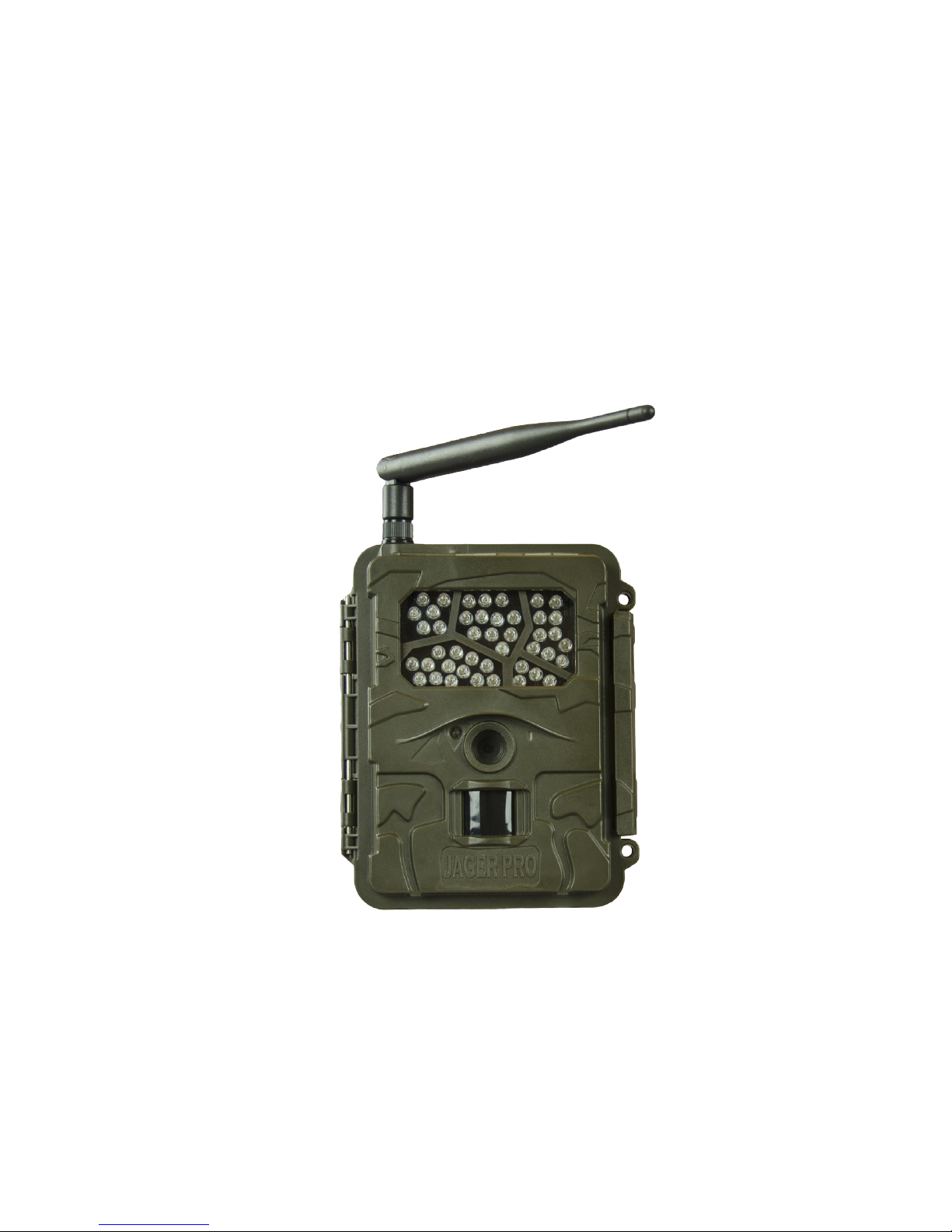
1. Inspect the outside of the camera body for any cracks which may cause
water or moisture to damage electronics.
2. Check for condensation in the IR LED bank.
3. Ensure the antenna is not loose, bent, broken or cracked.
4. Wipe excess dirt from camera lens with a soft cloth and use a moist cotton
swab with rubbing alcohol to thoroughly clean.
5. Apply even pressure to camera face and main body housing when closing
to ensure proper alignment of waterproof seal.
6. Ensure the latch is tightly securing the camera housing.
7. Clean inside the ambient light sensor port and PIR cover.
8. Inspect the DC and USB port covers for dry rot and damage.
CARE AND MAINTENANCE
2
3
4
7
7
8
6
8
Page 22
22
CAMERA ACCESSORIES
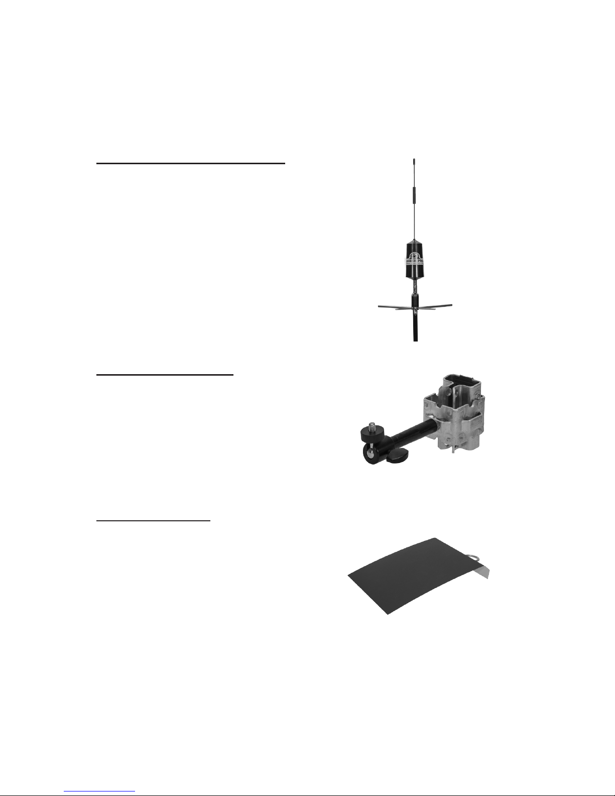
External 5 db Booster Antenna
This antenna is designed for areas where
cellular coverage is weak and enables users
to expand the usable range of the M.I.N.E.™
Cam.
• 5 db gain for remote areas
• 2.5 feet mast allows for higher vertical reach
in terrain such as valleys and thick tree cover
•10.5 feet coaxial cable is designed for high
quality signal transmission while providing
exibility to mount on a 16’ tall telescoping
pole.
T- Post Camera Mount
Allows the M.I.N.E.™ Cam to easily mount
in remote locations and above trap panels
using a T-Post.
• Aluminum and steel construction for
strength and durability
• Ball head allows the camera to be quickly
aimed with precision
T- Post Sun Shade
Protects the M.I.N.E.™ Cam from direct
sunlight and rain. Reduces sun ares and
over exposure of photos and videos due to
less than perfect camera positioning.
• Heavy duty metal construction for durability.
• Attaches directly to the T-Post over the
M.I.N.E.™ Cam using the included U-Bolt.
JAGER PRO™ offers several items for the M.I.N.E.™ Cam to increase the
versatility and function of the camera. These items may be purchased online
at www.jagerpro.com.
Page 23
23
PURCHASING A SIM CARD
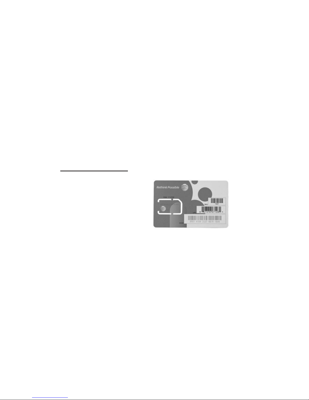
AT&T SIM cards must be purchased in person from an AT&T corporate
store; not an AT&T authorized retailer. Type “AT&T corporate store” into
a search engine (i.e. Google or Bing) and enter your zip code to nd the
nearest location. Users cannot request unlimited messaging packages
online. Please take this manual to your local AT&T corporate store to help
the rep.
http://www.att.com/shop/wireless/plans/prepaidplans.html
Messaging Packages: Text and photos can be sent instantly using a
M.I.N.E™ Cam. This AT&T SIM card is available with the 10¢ per minute
plan.
200 messages for $4.99/month
1000 messages for $9.99/month
Unlimited for $19.99/month
Ensure the AT&T representative adds “Automatic Renewal” to this Pay As
You Go SIM card. Packages are good for 30 days as long as your account
balance has not expired. The amount of the monthly package will be taken
out of the existing account balance every 30 days with “Automatic Renewal”.
REPLENISHING A SIM CARD
Upon initial purchase, record the SIM card phone number and expiration
date to simplify the process. Users may update the account monthly or pay
as many months in advance as you wish to remain active. Replenishing the
AT&T SIM card can be accomplished in three ways:
1. Visit the local AT&T corporate store in person.
2. Visit a local AT&T Express Service Kiosk.
a. Select- My Payment Options- Prepaid Accounts.
b. Enter wireless number then verify wireless number.
c. Select- Rell my prepaid account.
d. Select the amount to add to your Prepaid Account.
3. Pay by credit card over the phone at 1-800-331-0500.
a. Press 1 for other.
b. Press 0 to speak with a customer service representative. Users must
speak to a customer service rep as the SIM card does not have a pin
number to use the automated system.
We recommend an AT&T SIM card as their data package has unlimited text
and photo messaging for only $19.99 per month. It does not matter which
cellular company offers the best coverage in your area. Verizon and Sprint
network providers use CDMA technology and the camera requires GSM
technology (AT&T or T-Mobile) to operate.
AT&T customer service representatives are not trained to recognize a SIM
card can function in a wireless camera. They will debate this application is
possible and deny such a plan exists.
Page 24

GLOSSARY
CDMA- Code Division Multiple Access is a competing cell
phone service technology to GSM, which is the world’s most
widely used cell phone standard. Sprint, Verizon, and Virgin
Mobile use CDMA.
GPRS- General Packet Radio Service was early technology
to enable data communication on GSM networks. It has since
been replaced by better data technologies such as EDGE and
3G. It is based on GSM and compliments SMS.
GSM- Global System for Mobile communications. Cell phones
use a cellular provider’s GSM network by searching for cellular
phone towers in the nearby area. GSM has more complete
global coverage due to roaming and international roaming
contracts. AT&T and T-Mobile use GSM.
MMS- Multimedia Messaging Service. Takes SMS text
messaging a step further by allowing for longer lengths beyond
the traditional 160-character SMS limit.
PIR- Passive Infrared. A PIR sensor does NOT detect or
measure “heat”. It detects the infrared radiation emitted from
an object to detect motion. It triggers the camera to take a
photo or video when an object passes in front of the sensor.
SIM- Subscriber Identity Module. A small card used in GSM
devices to identify your account to the cellular carrier. Users
may change SIM cards between cameras and the phone
number and data plans transfer with it.
SMS- Short Message Service. SMS is also often referred to
as texting, sending text messages or text messaging. The
service allows for short messages to be sent from one cellular
device to another cellular device or from the Internet to a
cellular device.
SMTP- Simple Mail Transfer Protocol is an internet standard
for electronic mail (e-mail) transmission across Internet
Protocol (IP) networks. SMTP was rst dened by RFC 821
(1982, eventually declared STD 10) and last updated by RFC
5321 (2008) which includes the Extended SMTP (ESMTP)
additions and is the protocol in widespread use today.
24
Page 25

25
• Change Send Mode: Instant *140#0#
Response: Send instant photo
• Change Send Mode: Daily Report *140#1#
Response: Send daily report
• Change Send Off *140#2#
Response: Send is off
• Change Send Via: MMS *120#0#
Response: Send via mms.
• Change Send Via: Internet *120#1#
Response: Send via Internet
• Change Send To: Phone *130#0#
Response: Send phone.
• Change Send To: Email *130#1#
Response: Send to email
• Change Send To: Both *130#2#
Response: Send to both.
• Add Recipient: Phone Number *100#7065551212#
Response: Phone number added
• Delete Recipient: Phone Number *101#7065551212#
Response: Phone number deleted
• Close M.I.N.E.™ Gate *777#
Response: RF triggered
• Change Camera Mode: Photo *200#0#
Response: Set to photo mode
• Change Camera Mode: Video *200#1#
Response: Set to video mode
• Take a Photo and Send Now *500#
Response: Picture sending
• Check Cellular Antenna Signal *150#
Response: Signal: The signal is very weak/ The signal is weak/ The signal is good/
The signal is very good
• Check Battery Strength *201#
Response: Battery Level 1 to 5 (low to high)
• Set PIR Level to High *202#0#
Response: PIR sensitivity high
• Set PIR Level to Normal *202#1#
Response: PIR sensitivity normal
• Set PIR Level to Low *202#2#
Response: PIR sensitivity low
• Set PIR Level to Off *202#3#
Response: PIR sensitivity off
SMS COMMAND CODE LIST
Ensure the SMS Switch is ON in order for the camera to receive text
commands. The M.I.N.E™ Cam is able to receive text commands from up
to four phone numbers to perform these 22 different functions remotely. All
four phone numbers have the ability to send and receive SMS commands to
control the camera.
Page 26

JAGER PRO offers a complete line of Hog
Control Products, Services and Education
View our instructional video series online at:
PO Box 4006
Columbus, GA 31914
Phone: 706-718-9789
Email: [email protected]
Website: www.jagerpro.com
Like us on Facebook
www.facebook.com/JAGERPROHCS
 Loading...