

Page 1

Setup Instructions
for
WREX
Page 2

JAECO WREX
Wilmington Robotic EXoskeleton
The JAECO WREX is a functional upper
limb orthosis designed to enhance
movement for individuals with
neuromuscular disabilities. Its state-ofthe-art construction utilizes a light
weight exoskeleton that approximates
normal human anatomy. Linear elastic
bands are used both for balance and to
assist movement in three dimensions
against the effects of gravity. These
features provide for exceptional range of
motion to aid in a variety of therapeutic
and daily living activities.
This manual is designed to assist with
initial set-up and balance of the WREX
Mobile Arm Support
The WREX was developed with an NIH grant.
Special thanks to Tariq Rahman; PhD. Senior Research Engineer and Head (302) 651-6831 and
Whitney Sample; Research Design Engineer (302) 651-6868, Pediatric Engineering Research Lab
Department of Bio Medical Research A.I. duPont Hospital for Children, Wilmington, DE 19899
and in cooperation with Timothy Estilow; OTR/L and Deborah Humpl OTR/L,ATP Department of
Occupational Therapy of Children's Hospital of Philadelphia.
Page 3

Table of Contents
Section 1: Parts Description
1-1: Mount Parts Description
1-2: Arm Part Description
Section 2: Mount Attachment
2-1: Mount Base Attachment
2-2: Mount Link Attachment
2-3: MR-10 Mount Base
2-3: Preparing Mount Base
2-4: Mount Base Attachment
2-6: MR-8 Mount Base Attachment
2-6: Preparing Mount Base
2-7: Mount Base Attachment
2-8: Optional Side Attachment
2-9: MR-7 Mount Base Attachment
2-10: Preparing Backrest and Mount Base
2-11: Mount Base Attachment
2-13: Rotating Mount Arms
Attachment
Section 3: WREX Arm Setup
3-1: Measuring and Presetting Arm Components
3-1: Select and Pre-fit Forearm Support
3-2: Attach Forearm Support to WREX Arm
3-3: Measure and Preset Humeral Elevating Links
Section 4: Fitting and Adjustments with Client
4-1: Attaching the WREX Arm to the Wheelchair Mount
4-1: WREX Arm Attachment
4-2: Position WREX Shoulder Joint
4-2: Pitch Pivot Adjustment
4-3: Roll Pivot Adjustment
4-4: Place the Clients Arm into the WREX
4-4: Check for Appropriate Alignment
4-5: Application of Elastic Bands
4-6: Basic Adjustment for Functionality
4-7: Desired Functional Outcomes of the WREX
4-7: Removing the Arm from the WREX
4-8: Finalizing Setup
Page 4

Section
1
Part Description
Page 5
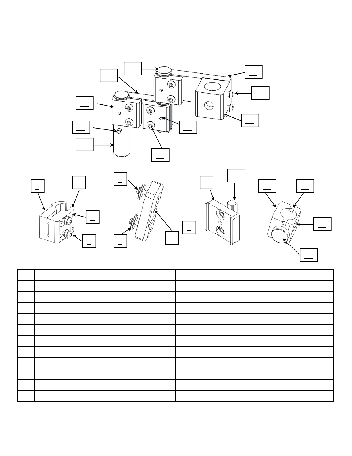
JAECO WREX
Mount Parts Description
19
18
20
21
17
22
16
23
15
24
1
2
5
9
10
11
12
3
8
13
4
1 MR-10 Mount Adapter 13 Attachment Hole
2 Moveable Jaw 14 Locking Knob
3 Jaw Locking Set Screw 15 Arm Mount Shaft
4 Base Clamp screw 16 Alignment Pin
5 Mount Screw 17 Arm Clamp
6 Reinforcement Washer 18 3 inch Arm
7 MR-7 Mount Adapter 19 Joint Pin
8 T-Nut Screws 20 4 inch Mount Arm
9 MR-8 Mount Adapter 21 Shaft Screw
10 Mr-8 T-nut 22 Shaft Mount Base
11 Arm Mount Base 23 Clamp Locking Set Screw
12 Alignment Slot 24 Arm Clamp Screw
6
7
14
1-1
Page 6
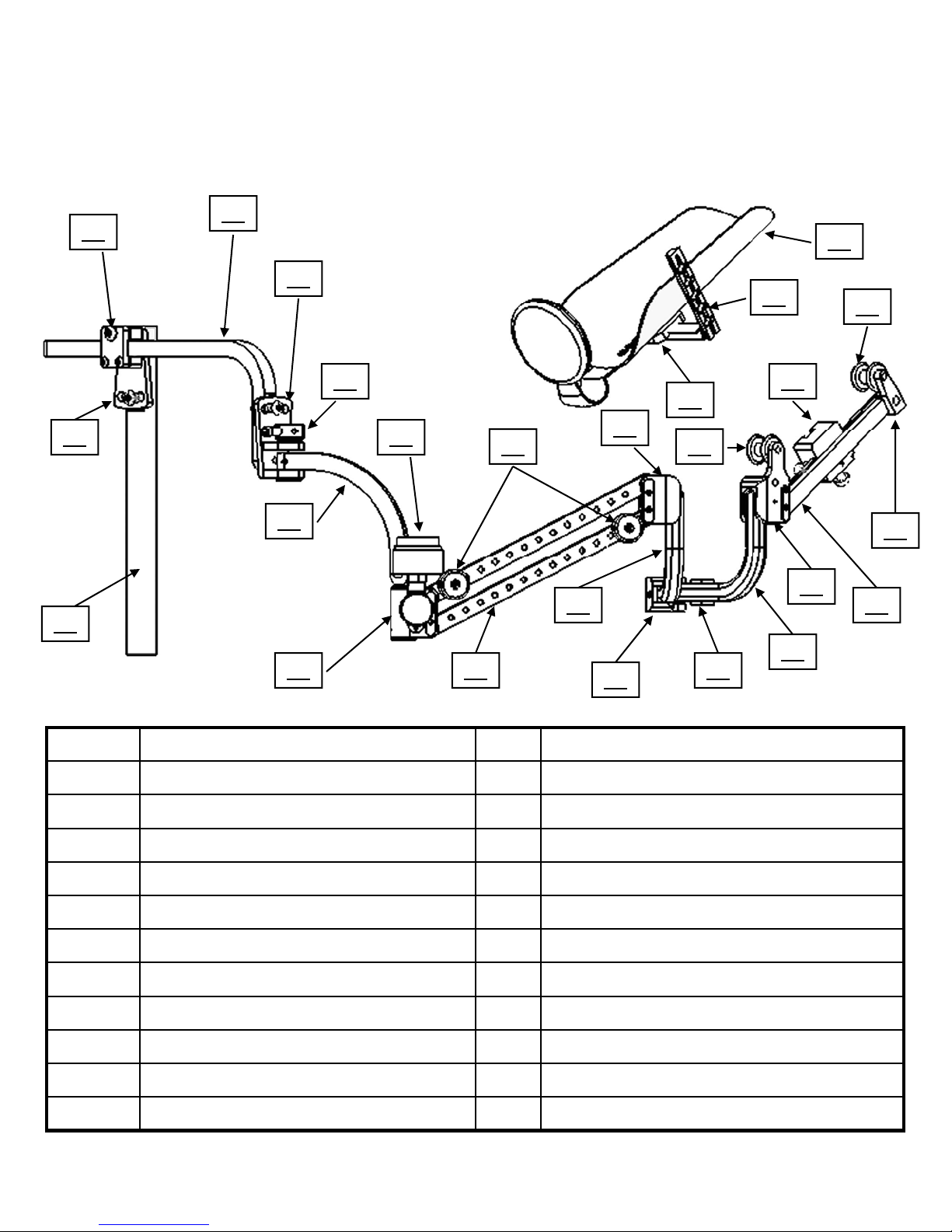
28
29
JAECO WREX
Arm Parts Description
30
46
48
35
31
27
32
26
34
26 Pitch Mount Shaft 38 Elevator J-Link
27 Pitch Pivot 39 Elbow Pivot
28 Pitch Pivot Cover 40 Elbow J-Link
33
35
36
37
38
39
44
47
35
45
42
43
40
41
29 Pitch Link 41 Band Cradle
30 Roll Pivot 42 Forearm Pivot
31 Lateral Stop 43 Forearm Link
32 Shoulder Link 44 Slide Saddle
33 WREX Level 45 Band Spool Pivot
34 Upper Humeral Pivot 46 L-Bar
35 Band Spool 47 Forearm Support Mount Plate
36 Humeral Links 48 Forearm Support
37 Lower Humeral Pivot
1-2
Page 7

Section
2
Mount Attachment
Page 8
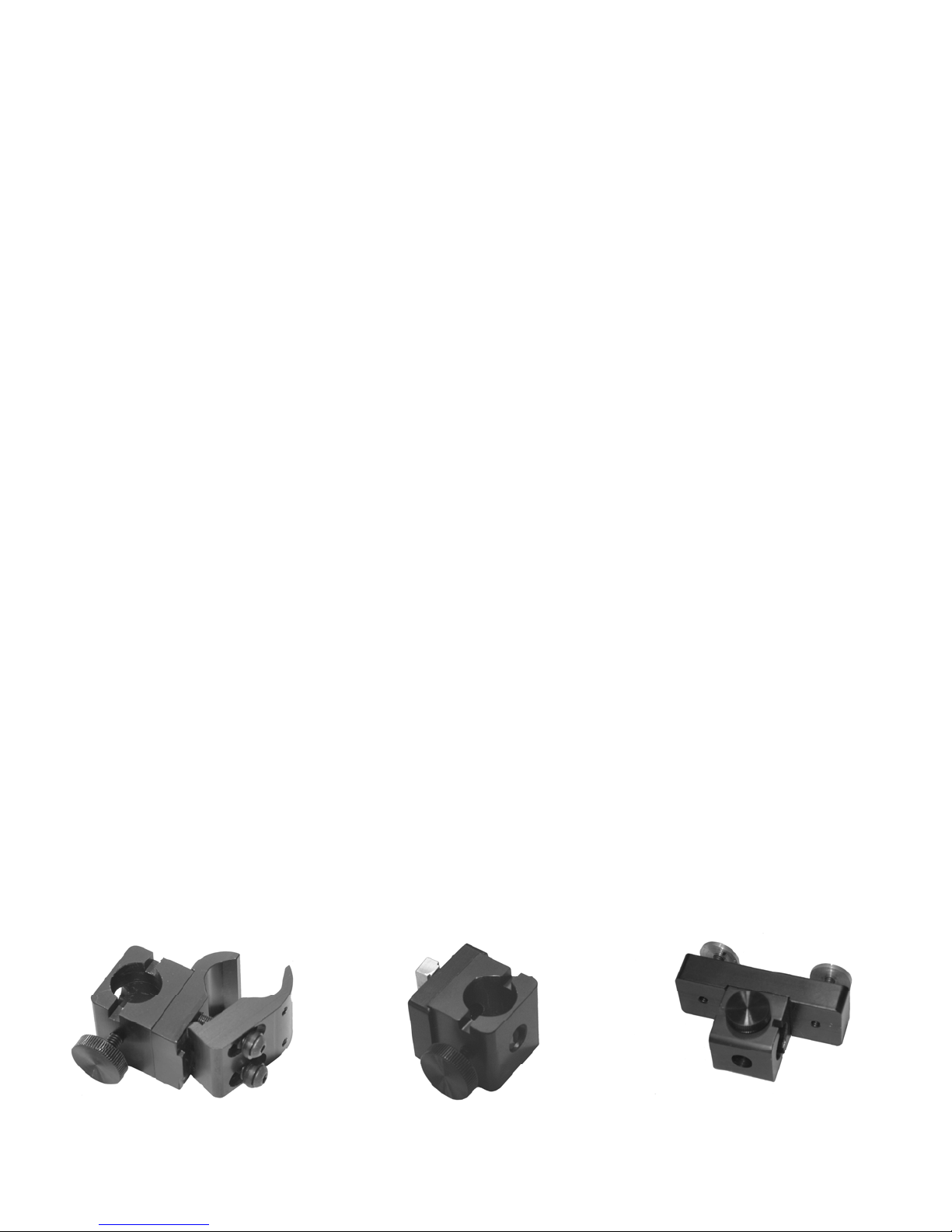
Mount Base Attachment
The WREX can be attached to most common
wheelchairs and mobility seating systems utilizing
one of the three Mount Bases provided with the arm.
These are the same attachment systems that are the
basis of our JAECO Mount Relocator.
It is essential that you identify the best attachment
position. Then choose from one of the three mount
bases for either;
(1) a Tubular Mount: MR-10
(2) a Keyed Back Post: MR-8
(3) direct attachment to a Molded Backrest: MR-7
MR-10 MR-7MR-8
2-1
Page 9
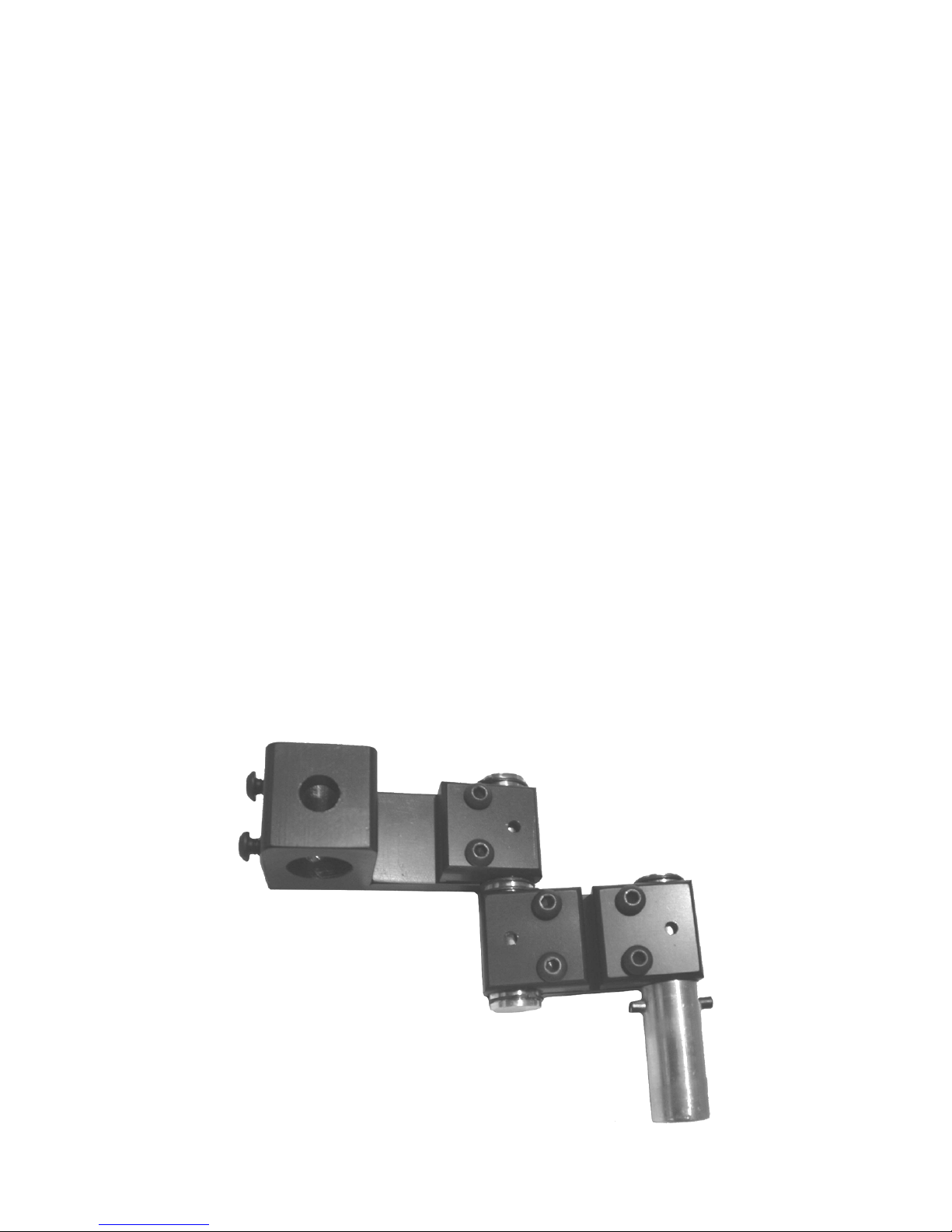
Mount Link Attachment
The Mount Link for the WREX is designed so that
each of the three articulation; at the Mount Base,
at the Link Joint and at the Pitch Mount Shaft can
pivot 360 degrees. This will allow for the ability to
locate the Pitch Mount Shaft in a large variety of
locations to optimize its position and/or avoid
other apparatus attached to the chair.
The Mount Links will be shipped with the Clamp
Screws and Clamp Locking Set Screws loosened for
ease of application.
2-2
Page 10
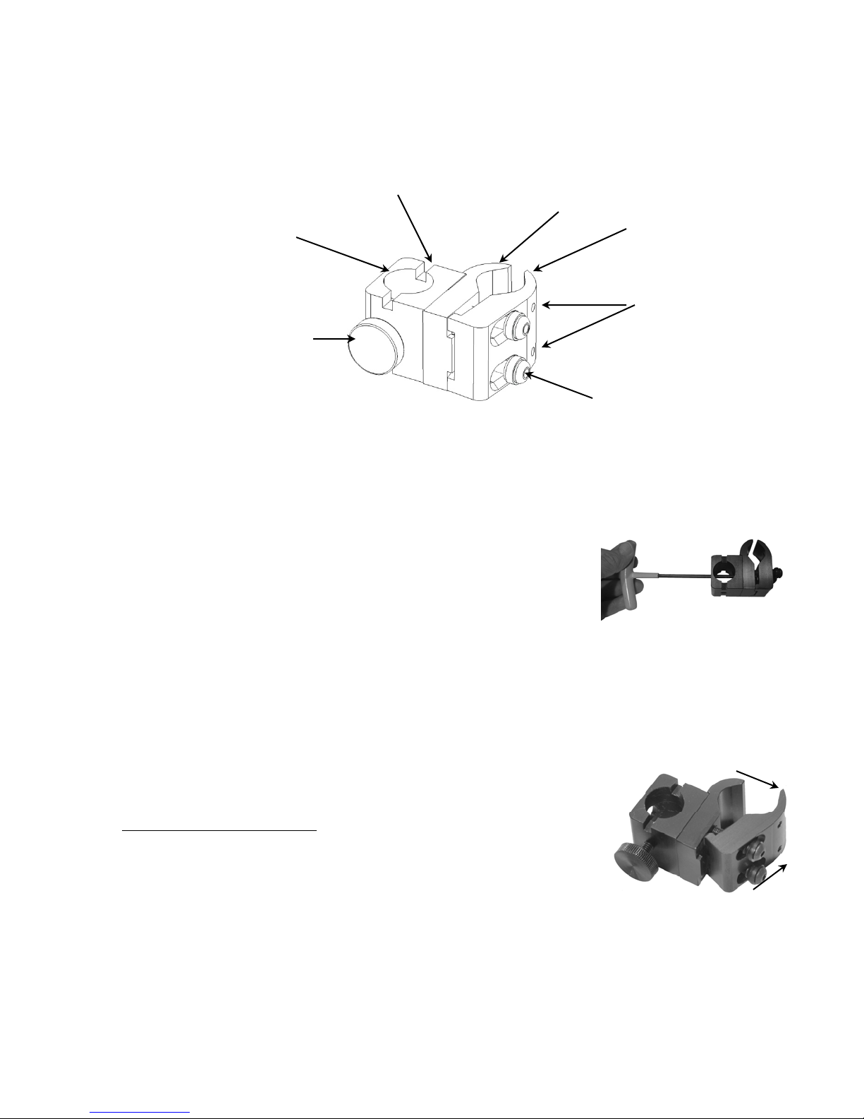
MR-10
Mount Base Installation
Alignment Slot
MR-10 Mount Adapter
Arm Mount Base
Locking Knob
Preparing Mount Base
1. Orient the Arm Mount Base as in illustration above.
Insert the Mount Base Screw (supplied with
Arm Mount Base) thru the Attachment Hole to
the MR-10 Mount Adapter. Using large T-Wrench
secure these two parts.
Moveable Jaw
Jaw
Locking Set
Screws
Base Clamp
Screws
2. Loosen Clamp Screws using large T-Wrench
Do not remove screws
its widest position by pushing the Moveable
Jaw forward and pulling it outward as shown in
photo.
and open clamp to
2-3
Page 11
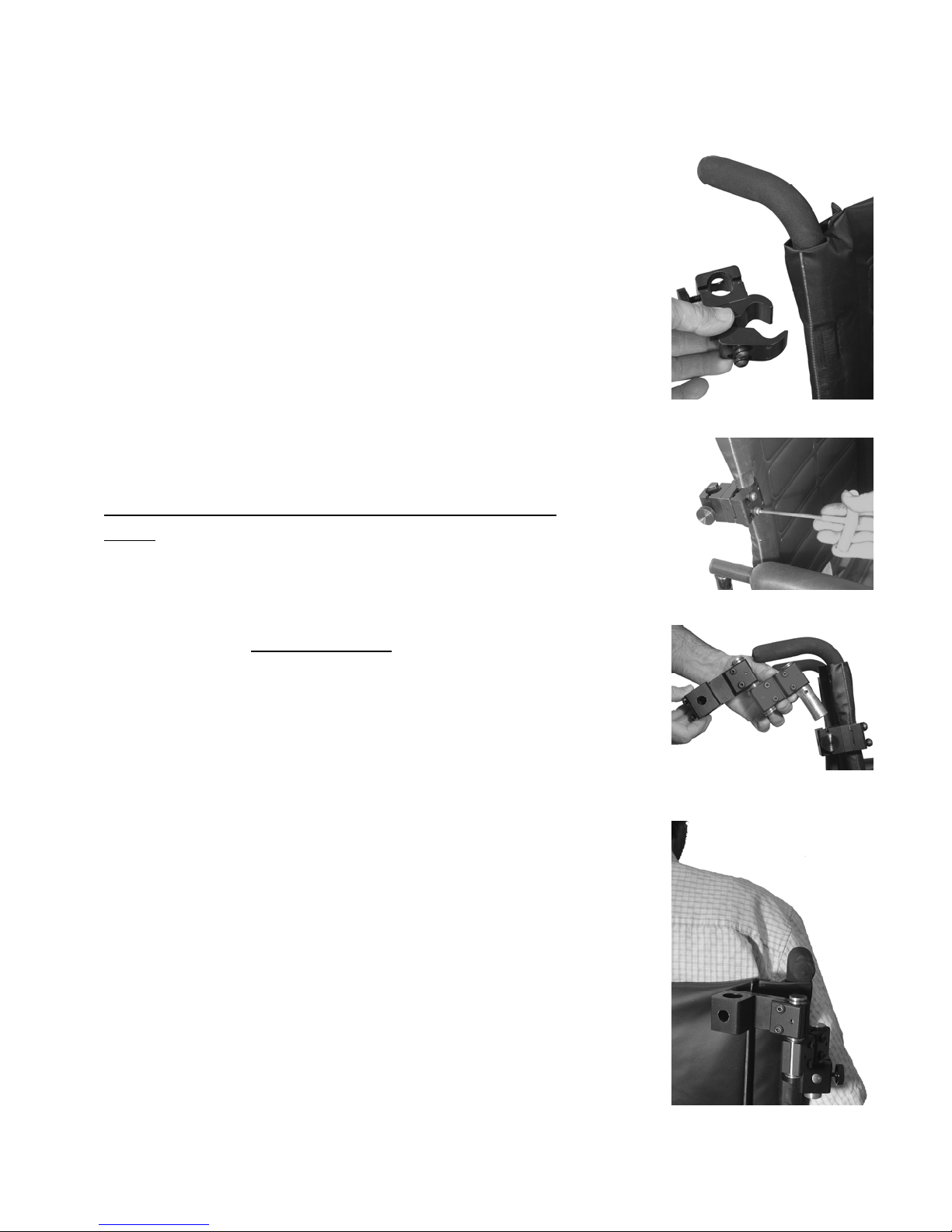
Mount Base Attachment
1. In this open position, apply the mount to the
wheelchair upright (back post).
Note: Mount positioning (angle) will vary depending on
wheelchair style.
2. Position the mount so that the top of the mount is
not more than 6 inches below the top of the clients
shoulder.
3. Tighten Base Clamp Screws.
Do not tighten Jaw Locking Set Screws at this
time.
Note: Adjustments in position may be necessary for
optimal function.
4. Loosen but do not remove the Locking Knob
on the Arm Mount Base.
5. Position the Mount Link so that the Alignment
Pin in the Arm Mount Shaft is aligned with
the Alignment Slot of the Arm Mount Base.
Insert the shaft into the base and tighten the
Locking Knob.
6. Preposition the Mount Links so that the
Shaft Mount Base that receives the Pitch
Mount Shaft is located in the lateral 1/3 of
the clients torso on the side which you
intend to use the WREX Arm.
2-4
Page 12
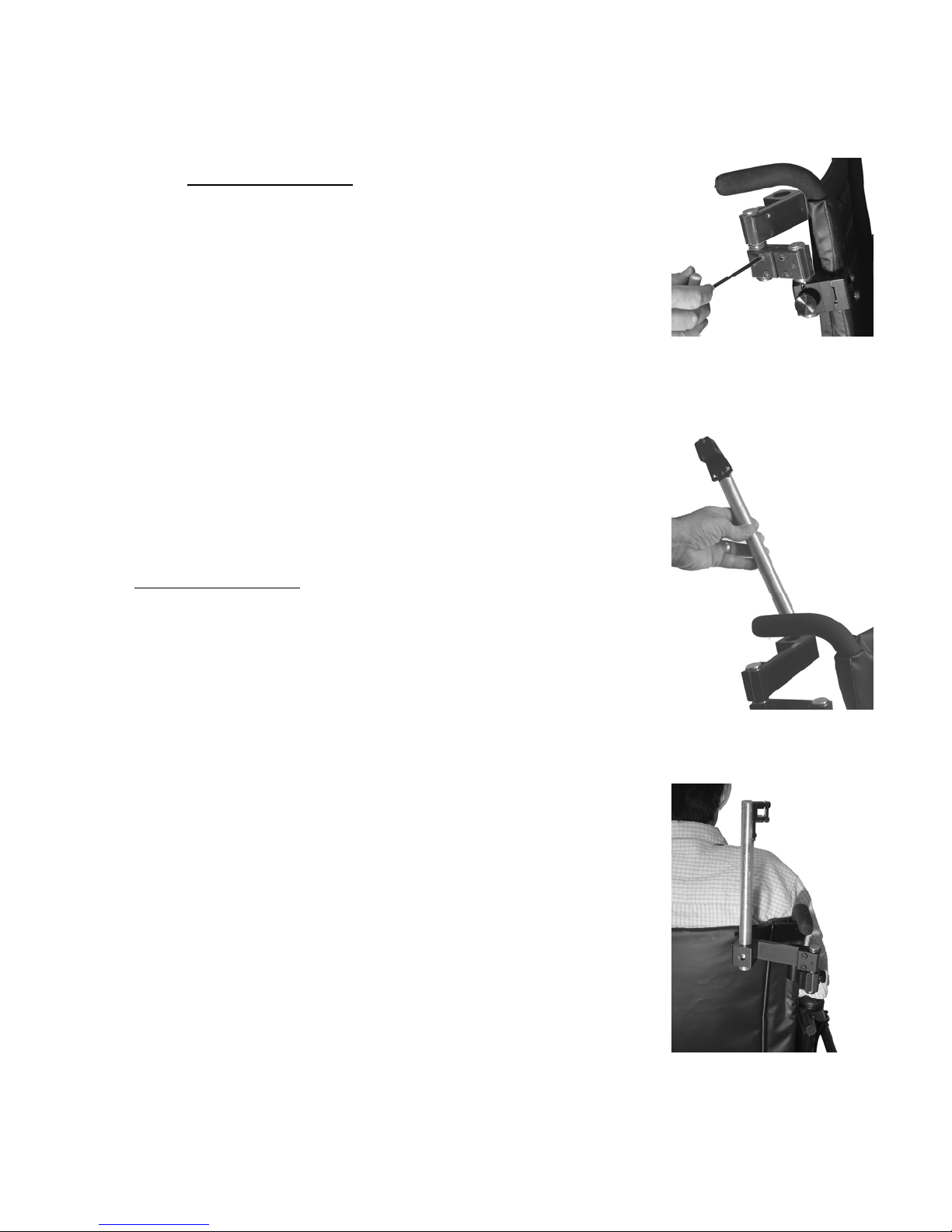
7. Snug but do not tighten the six Clamp Screws
using the large T-Wrench. Add enough
tension so that the joints do not move easily
but can be repositioned if required to optimize
the arm alignment.
Note: Do not tighten the Clamp Locking Set
Screws at this time.
8. Hold the Pitch Mount Shaft so that the black
Pitch Pivot is at the proximal end, the hole
through the Pitch Pivot is in the line of
progression of the chair and the plate of the
pivot is facing laterally. Insert the Pitch
Mount Shaft into the Shaft Mount Base. Snug
but do not tighten the Shaft Screws on the
Shaft Mount Base.
9. With client sitting in the chair align the
square hole in the Pitch Pivot approximately
1 ½ inches above their shoulder.
2-5
Page 13
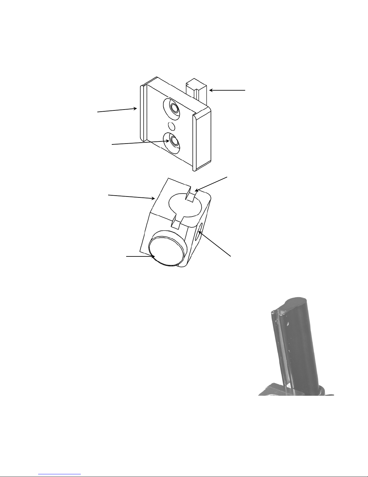
For use on some Invacare and Motion Concept Seating
MR-8
Mount Base
Adapter
T-Nut
Screws
Arm Mount Base
MR-8
Mount Base Installation
Systems
T-Nut
Alignment Slot
Locking Knob
Preparing Mount Base
1. Locate and mark an area 2 to 8 inches below the
clients shoulder on the Keyed Back Post of the
wheelchair.
2. Locate and remove ( if applicable) the plastic cap
from the top of the Keyed Back Post of the
wheelchair.
Note: Adjustments in position may be necessary for
optimal function.
Attachment Hole
Keyed
Back Post
2-6
Page 14
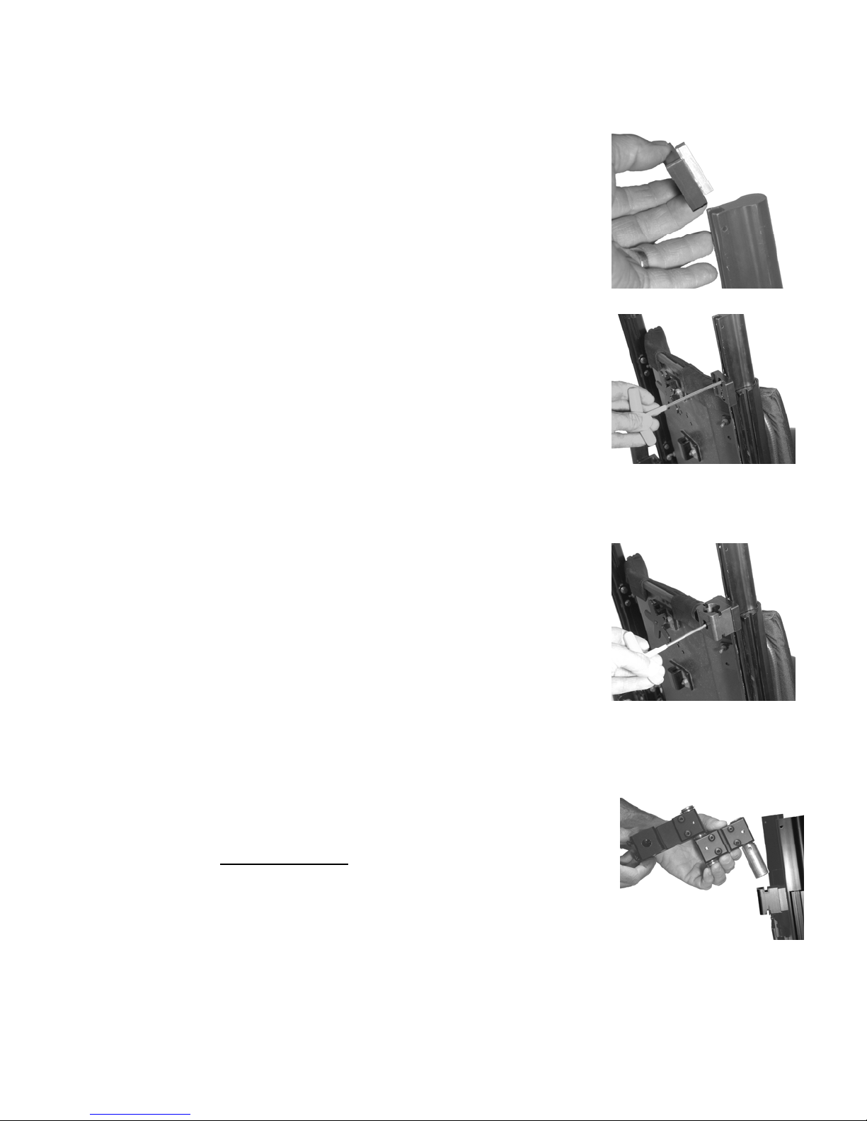
Mount Base Attachment
1. Using the large T-Wrench loosen, Do not remove,
the two T-Nut Screws on the MR-8 Mount Adapter.
2. Insert the T-Nut into Keyed Back Post channel and
position the MR-8 Mount Adapter at the marked
location (see Preparing Mount Base #1). Tighten the
two T-Nut screws.
Note: It may be necessary to remove the Spreader Bar
(bar that links both Keyed Back Posts) to attach the
Mount Adapter below and sometimes above the
marked location. Loosen, Do not remove, all four
Spreader Bar bolts using 7/16 inch wrench and
slide bar out of Keyed Back Posts.
3. Orient the Arm Mount Base as shown in illustration.
Insert the Mount Base Screw (supplied with
Arm Mount Base) thru the Attachment Hole to
the MR-8 Mount Adapter. Using the large T-Wrench
secure these two parts.
Note: If Spreader Bar was removed, reattach Spreader
bar, secure in place, and insert the plastic cap that
was removed in step 4 of Preparation instructions
Page 2-4.
Note: Adjustments in position may be necessary for
optimal function.
4. Loosen but do not remove the Locking Knob
on the Arm Mount Base.
5. Position the Mount Link so that the Alignment Pin in
the Arm Mount Shaft is aligned with the Alignment
Slot of the Arm Mount Base. Insert the shaft into the
base and tighten the Locking Knob.
2-7
Page 15
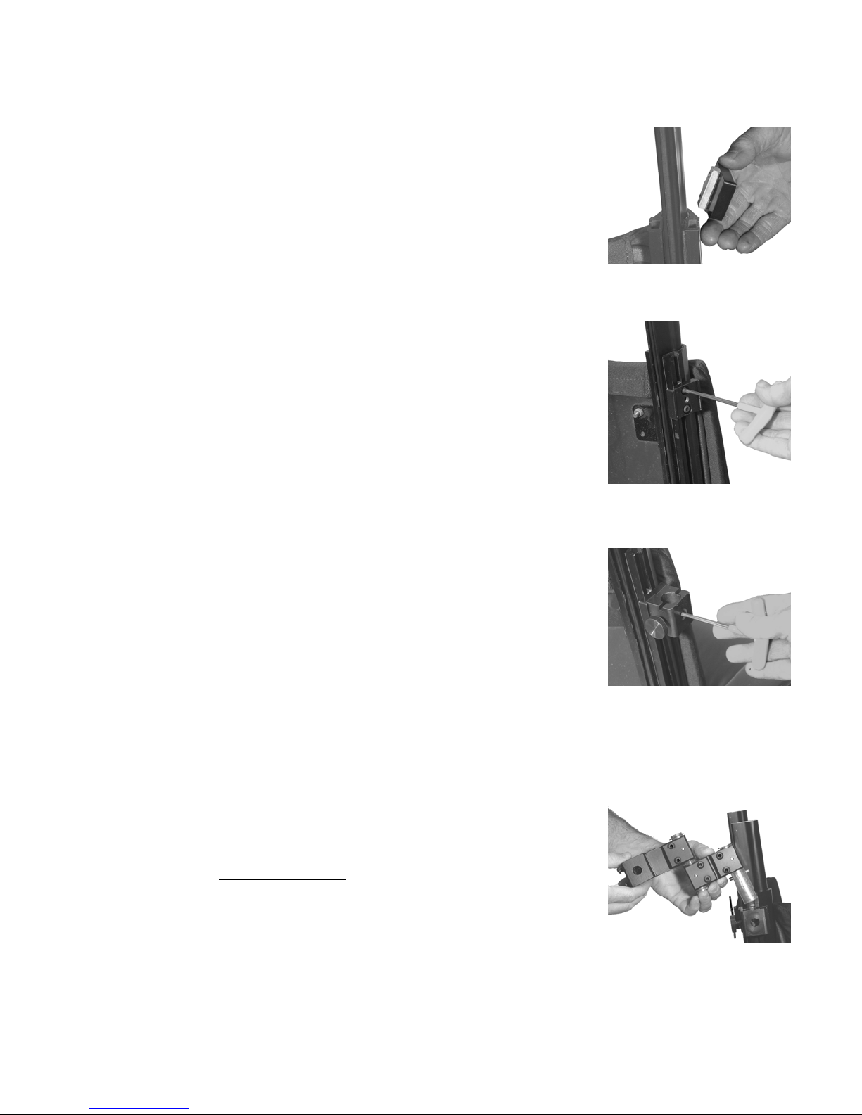
Optional Side Attachment
1. Using the large T-Wrench loosen, Do not remove, the two
T-Nut Screws on the Mount Adapter.
2. Insert the T-Nut into Keyed Back Post channel and position the
MR-8 Mount Adapter at the marked location (see Preparing
Mount Base #1). Tighten the two T-Nut screws.
3. Orient the Arm Mount Base as shown in illustration.
Insert the Mount Base Screw (supplied with
Arm Mount Base) thru the Attachment Hole to
the MR-8 Mount Adapter. Using the large T-Wrench
secure these two parts.
Note: Adjustments in position may be necessary for
optimal function.
4. Loosen but do not remove
the Locking Knob
on the Arm Mount Base.
5. Position the Mount Link so that the Alignment Pin in
the Arm Mount Shaft is aligned with the Alignment
Slot of the Arm Mount Base. Insert the shaft into the
base and tighten the Locking Knob.
2-8
Page 16
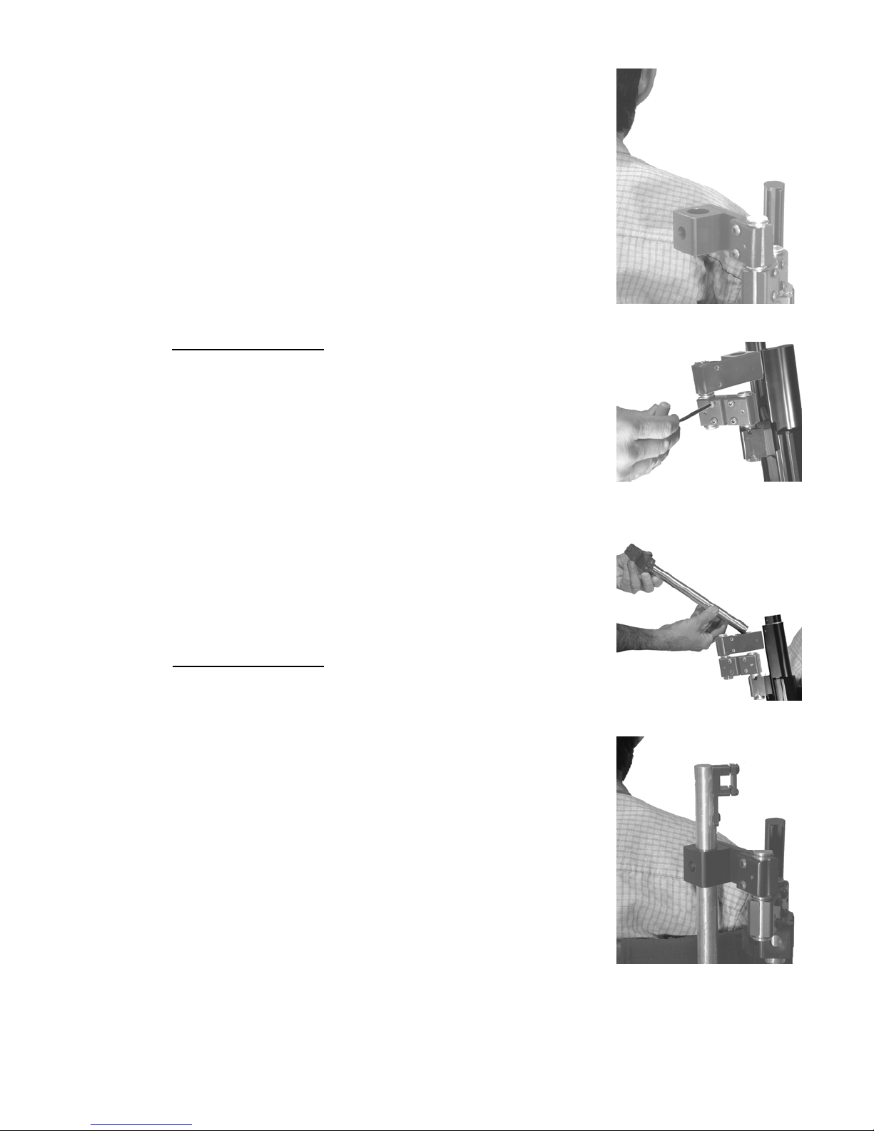
6. Preposition the Mount Links so that the Mount
Shaft Base that receives the Pitch Mount Shaft is
located in the lateral 1/3 of the clients torso on
the side which you intend to use the WREX Arm.
7. Snug but do not tighten the six Clamp Screws
using the Large T-Wrench. Add enough
tension so that the joints do not move easily
but can be repositioned if required to optimize
the arm alignment.
Note: Do not tighten the Clamp Locking Set
Screws at this time.
8. Hold the Pitch Mount Shaft so that the black Pitch
Pivot is at the proximal end, the hole through the
Pitch Pivot is in the line of progression of the chair
and the plate of the pivot is facing laterally. Insert
the Pitch Mount Shaft into the Mount Shaft Base.
Snug but do not tighten the Shaft Screws on the
Mount Shaft Base.
9. With client sitting in the chair align the square
hole in the Pitch Pivot approximately 1 ½ inches
above their shoulder.
2-9
Page 17
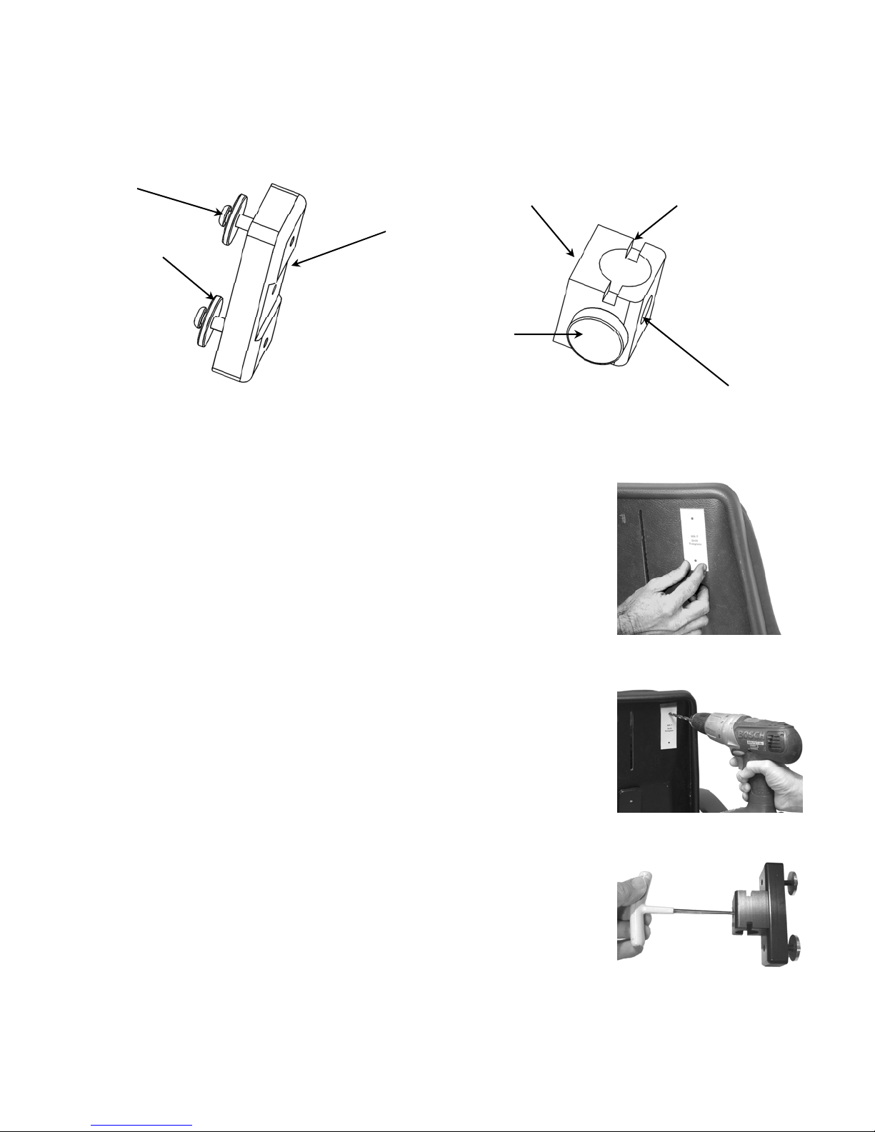
MR-7
Mount Base Installation
For use on some Permobil and Other Seating Systems
Mount Screw
Reinforcement
Washer
MR-7
Mount Base
Adapter
Locking Knob
Arm Mount Base
Preparing Backrest and Mount Base
1. Remove backrest cushion.
2. Tape the template on the back of the backrest 1 ½ to
2 inches down from upper edge and as close to the
midline as possible.
Note: Place Base Drill Template on flattest area of
backrest
Alignment Slot
Attachment Hole
4. Use drill bit supplied and drill the two marked holes.
5. Orient the Arm Mount Base as shown in illustration.
Insert the Mount Base Screw (supplied with
Arm Mount Base) thru the Attachment Hole to
the MR-7 Mount Adapter. Using large T-Wrench
secure these two parts.
2-10
Page 18
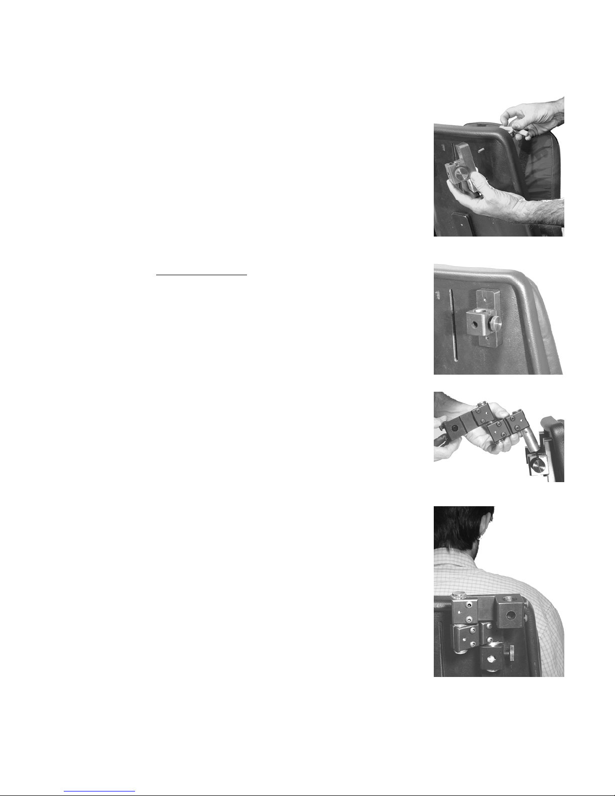
Mount Base Attachment
6. Using the large T-Wrench remove the two Mount
Screws with Reinforcement Washers from the MR-7
Mount Base. Insert the screws with Reinforcement
Washers through the drilled holes and into the
MR-7 Mount Base. Tighten the two Mount Screws
7. Loosen but do not remove the Locking Knob
on the Mount Base.
8. Position the Mount Link so that the Alignment
Pin in the Arm Mount Shaft is aligned with
the Alignment Slot of the Arm Mount Base. Insert
the shaft into the block and tighten the
Locking Knob.
9. Preposition the Mount Links so that the Mount
Shaft Base that receives the Pitch Mount Shaft is
located in the lateral 1/3 of the clients torso on
the side which you intend to use the WREX Arm.
2-11
Page 19
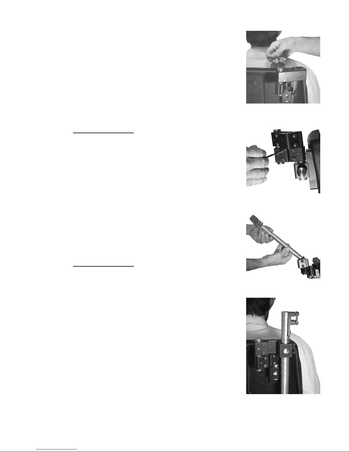
Note: Check to insure the Clamp Screws are accessible.
If they are not complete the steps on page 2-13.
10. Snug but do not tighten the six Clamp Screws
using the Large T-Wrench. Add enough
tension so that the joints do not move easily
but can be repositioned if required to optimize
the arm alignment.
Note: Do not tighten the Clamp Locking Set
Screws at this time.
11. Hold the Pitch Mount Shaft so that the black Pitch
Pivot is at the proximal end, the hole through the
Pitch Pivot is in the line of progression of the chair
and the plate of the pivot is facing laterally. Insert
the Pitch Mount Shaft into the Mount Shaft Base.
Snug but do not tighten the screws on the Mount
Shaft Base.
12. With client sitting in the chair align the square hole
in the Pitch Pivot approximately 1 ½ inches above
their shoulder.
2-12
Page 20
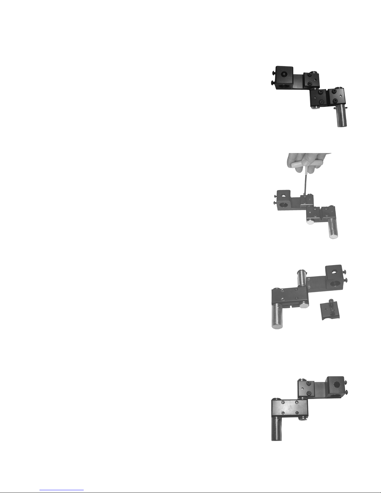
Rotating Mount Arms
1. Lay the Mount Arm flat on work surface.
2. Using the large T-Wrench remove the two Clamp
Screws and the Arm Clamp from the 4 inch Mount
Arm.
3. Rotate the 3 inch Arm and position the 4 inch
Mount Arm onto the Joint Pin as shown. Replace
the Arm Clamp and the two Clamp Screws. Tighten
the Clamp Screws.
Note: The Clamp Screws on the 3 inch Arm and
the 4 inch Mount Arm should be facing opposite
directions as shown in photo.
2-13
Page 21

Section
3
WREX Arm Setup
Page 22

Measuring and Presetting Arm Components
The WREX is designed for optimum functionality when
all of its exoskeletal articulations can approximate
the patients anatomical joints. Although this can
not be exact, careful measurement and pre-fitting of
the arm components will maximize the outcome.
We recommend fittings and assemblies in this section
should not
be done while the arm is attached to the
wheelchair.
3-1
Page 23
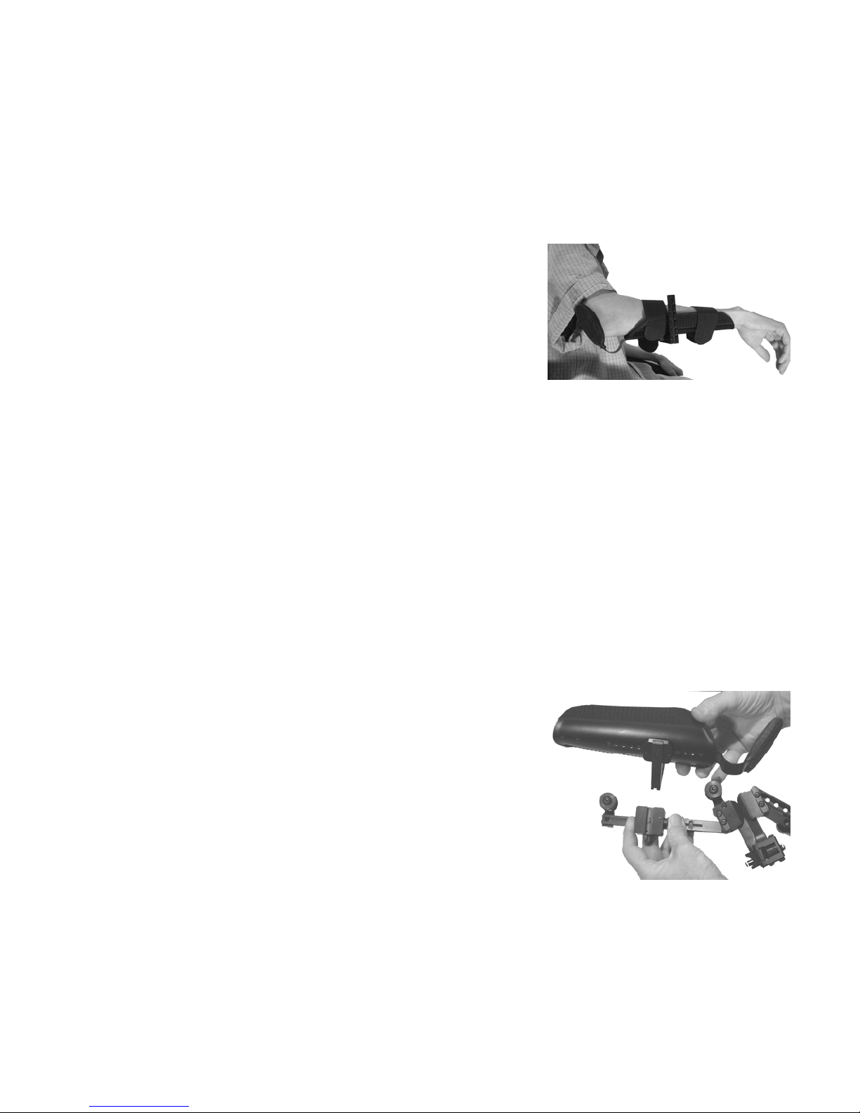
Select and Pre-fit Forearm Support
1. Measure the distance from the Olecranon to
the Ulna Styloid then subtract one inch.
Insure size and side is correct from the chart
attached page 4-8.
2. Place the clients arm into the forearm
support. When the clients arm is strapped
in, the fit should be snug but not tight. The
Forearm support circumference can be
adjusted by squeezing the edges of the trough
together. This does require a great deal of
force. Use of a vice or small rubber mallet may
be required. Alternately padding may be added
to insure a intimate fit.
3. Remove the clients arm from the Forearm
Support.
Attach Forearm Support to WREX Arm
1. While depressing the button on the side of
the Forearm Support Slide Saddle.
2. Slide the L-Bar into the Slide Saddle from the
top.
3. Release button on the Slide Saddle to lock the
Forearm Support in the first (highest) position
on the L-Bar.
3-2
Page 24
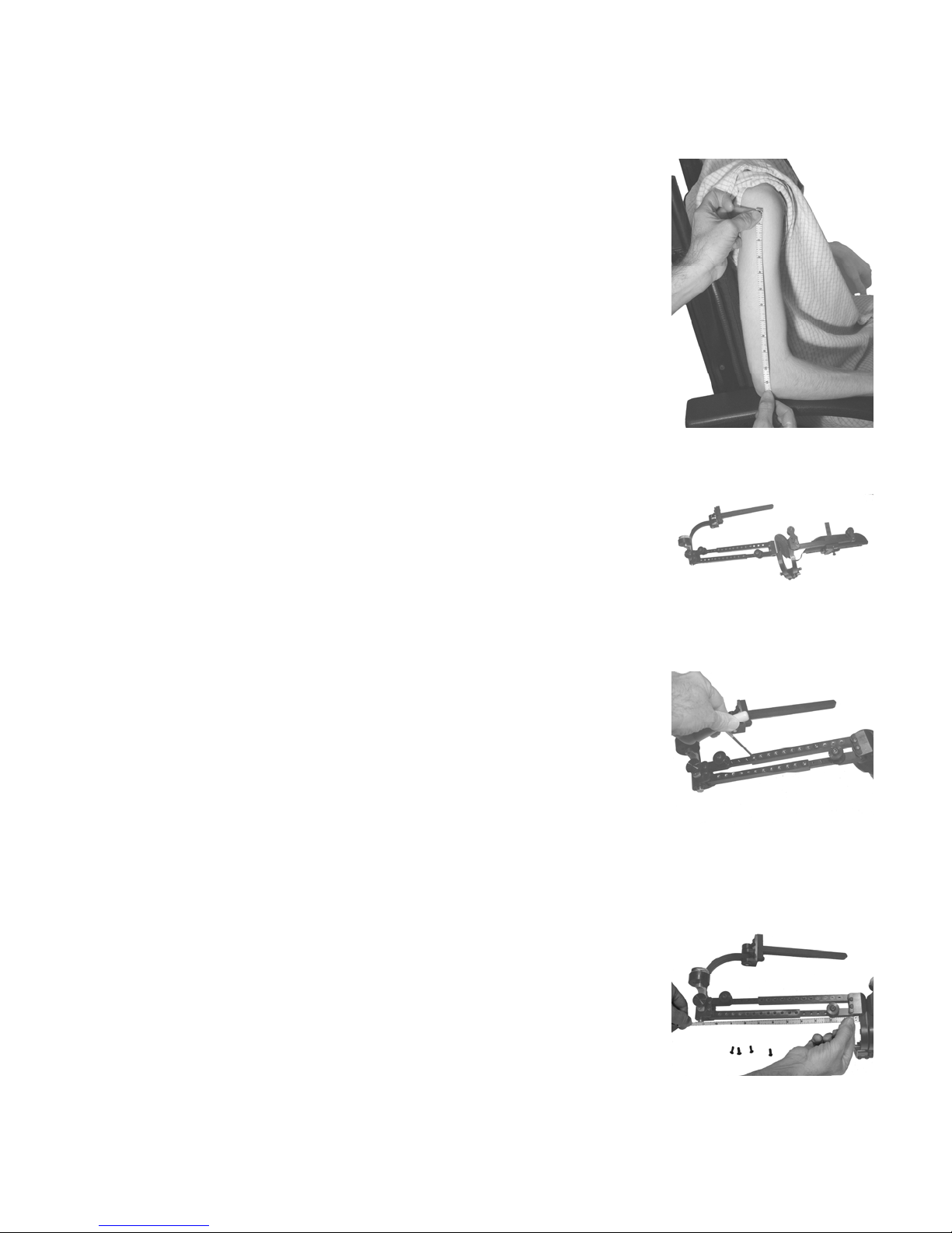
Measure and Preset Humeral Elevating Links
1. On the side you plan to fit the orthosis take a
measurement from the head of the humerus
to the lateral epicondyle. Record this
measurement.
2. Lay the WREX arm flat on a work surface.
3. Using the medium T-Wrench remove the Four
screws that connect the sections of the upper
and lower Humeral Elevating Links
3. By sliding the link sections on each other
shorten or lengthen the Humeral Links until the
distance between the centers of the Upper and
Lower Humeral Pivots is equal to the
measurement from Step 1.
4. Reinsert and tighten the Four screws to
secure both links.
3-3
Page 25

Section
4
Fitting and
Adjustments with
Client
Page 26
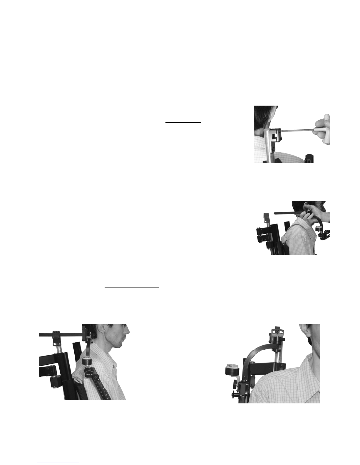
Attaching the WREX Arm to the Wheelchair Mount
Transfer the patient into the Wheelchair
WREX Arm Attachment
1. Using the large T-Wrench loosen but do not
remove the top screw on the Pitch Plate
Cover.
2. Orient the WREX arm with the slot in the Roll
Pivot facing up.
3. Slide the Pitch Link into the square hole of
the Pitch Pivot.
Note: The WREX arm is designed to have as little friction as possible at all of its
articulations. For client safety please be sure to control the entire device as
you are attaching the arm and making adjustments.
4-1
Page 27
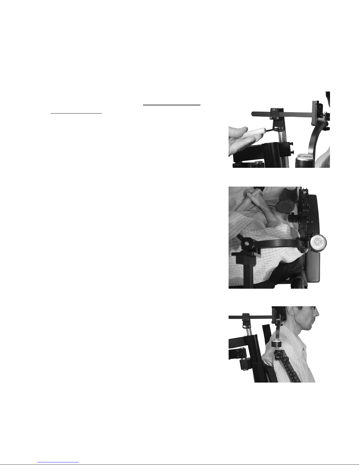
Position WREX Shoulder Joint
Pitch Pivot Adjustment
1. Using the large T-Wrench, while supporting
the WREX arm, loosen the screw on the Pitch
Pivot adjustor.
2. With the aid of the Bubble Level position the
Pitch Link so that it is horizontal and parallel
to the floor.
3. Tighten the Pitch Plate Adjuster Screw
4. Slide the Pitch Link into a position where the
articulation of the Roll Pivot is in line with the
top of the shoulder joint with a minimum of
1½ inches of space between the skin and the
bottom of the pivot.
Note: Positioning of the Shoulder Link may
require loosening of the two screws on the
Shaft Mount Base or repositioning the
Mount Links
4-2
Page 28
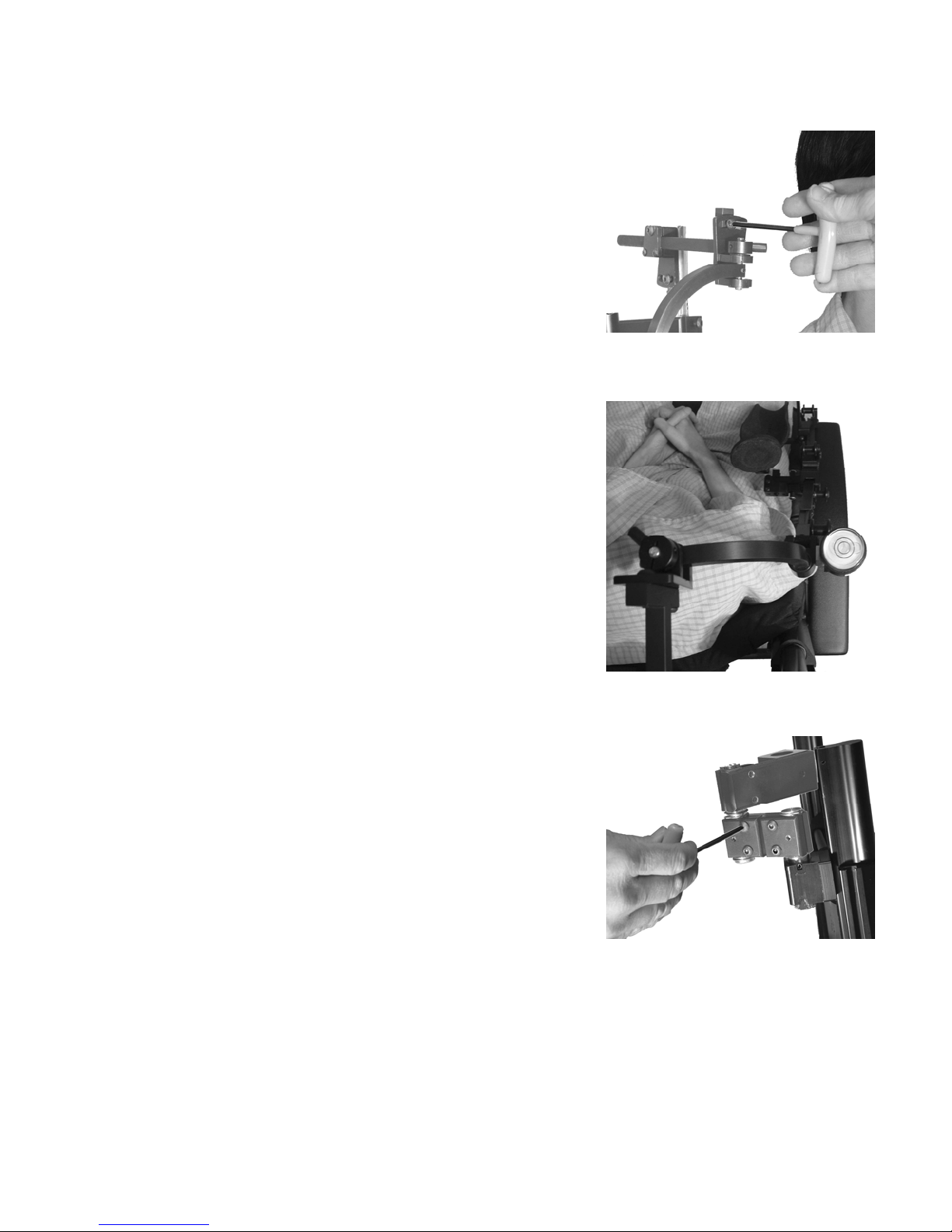
Roll Pivot Adjustment
1. Using the large T-Wrench loosen the screw
for the Roll Pivot Adjustment.
2. With the aid of the bubble level roll the
adjustment medially or laterally until the
bubble is centered.
3. Tighten the Roll Pivot Adjuster Screw.
4. Using the large T-Wrench tighten all six of
the Mount Link Clamp Screws and the two
Mount Shaft Base Screws.
5. Recheck that the bubble in the level is still
centered. Adjust the Pitch Pivot or Roll Pivot
as necessary.
Caution: Do not put the clients arm into the orthosis until all
previous steps in this section have been completed.
4-3
Page 29
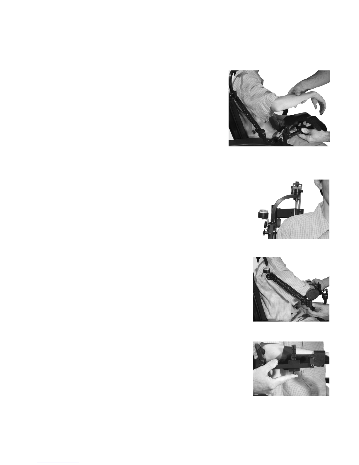
Place the Clients Arm into the WREX
Because the WREX operates with band tension it must carefully be handled
during arm placement to prevent injury
1. With one hand support the WREX arm under
the Forearm Support.
2. Using your other hand lift the clients arm with
his/her elbow flexed and place it in the Forearm
Support. Insure that the back of elbow is
touching the elbow pad
3. Secure Velcro straps
Check for Appropriate Alignment
1. Roll Pivot joint should be 1½ inch above the
top of the shoulder to allow full shoulder range
of movement.
1. Adjust with the height of the Mount Shaft
2. Upper Humeral Pivot should be aligned with
the head of the humerus and the Lower
Humeral Pivot should align with the lateral
epicondyle.
1. Adjust by shortening or lengthening the
Humeral Elevating Links
3. Elevator Links should align with the shaft of the
humerus
1. Adjust the height of the Roll Pivot above
the shoulder
4. Clients elbow should be above the center of the
Elbow Pivot
1. Adjust depressing the bottom button on
the forearm Slide Saddle and moving the
forearm support forward or back.
Note: Insure there is clearance between the elbow area
of the Forearm Support and the Elbow Pivot,
when the clients arm is flexed.
4-4
Page 30
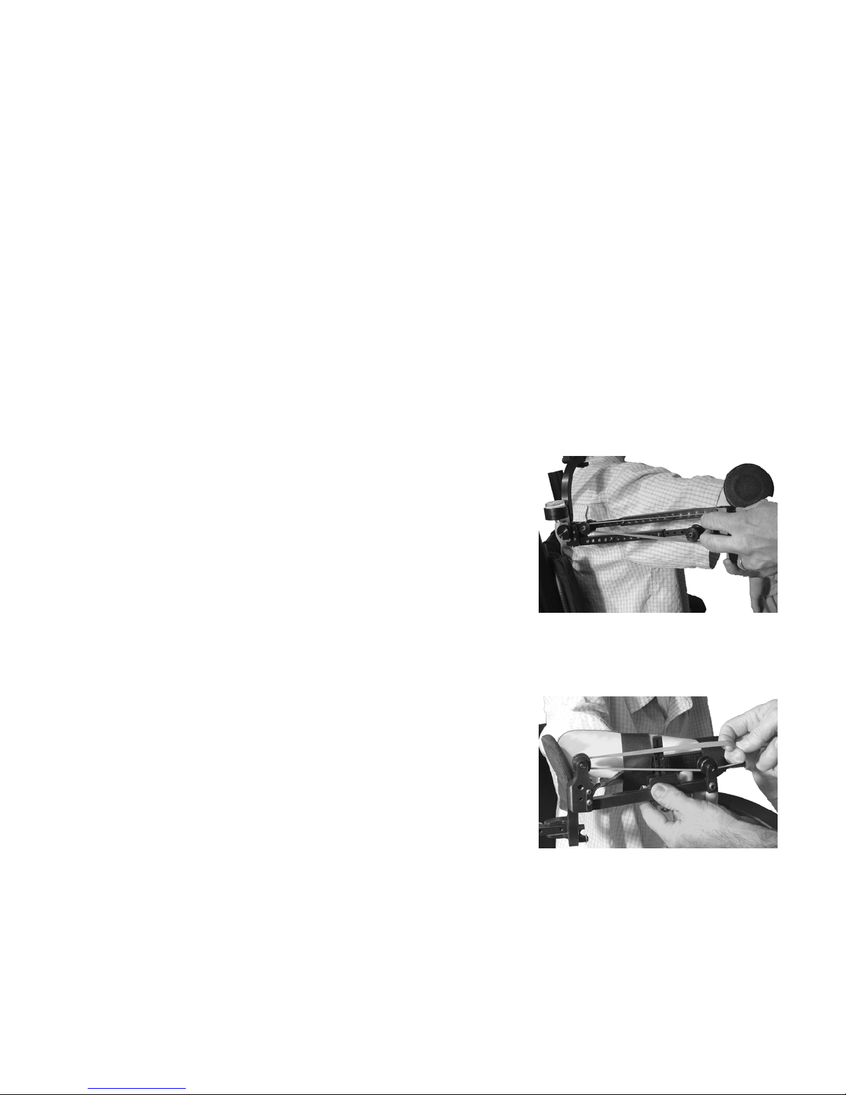
Application of Elastic Bands
The number of bands varies depending on the weight of the clients arm and their
strength
The optimal number of bands allows for the client to move through their
maximal range of movement. The client must be able to return to starting
location to avoid the arm floating in space without control.
JAECO supplies three sizes of elastic bands:
Blue: Large
Red: Medium
Beige: Light
Note: Start with the largest bands then use the smaller bands to “fine tune” the
clients movements.
1. Supporting the clients arm at the elbow with
one hand, loop elastic bands one at a time
over the Band Spools on the Humeral
Elevating Links until the arm begins to “float” in
space.
2. Supporting the clients forearm with on hand,
loop elastic bands one at a time over the Band
Spools on the Forearm Link until the client is
able to easily flex and extend their elbow.
4-5
Page 31
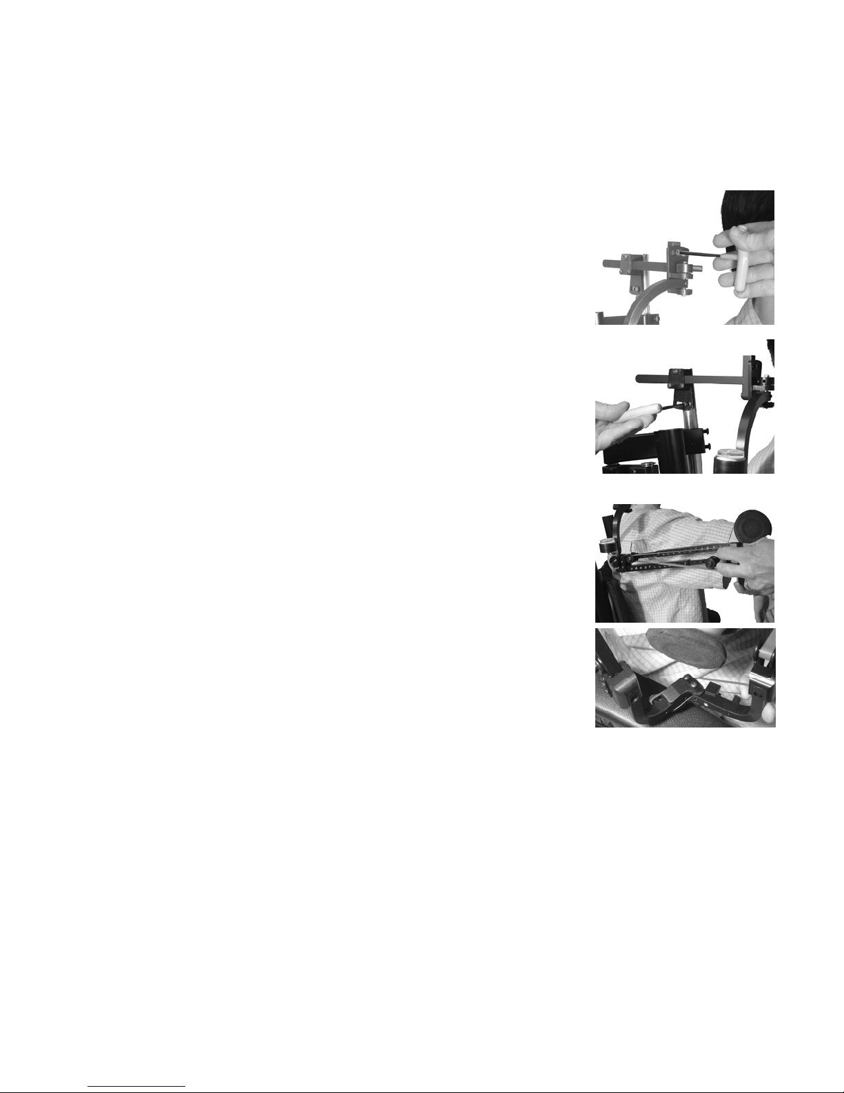
Basic Adjustment for Functionality
Ask the client to move horizontally from side to side
then toward and away from the body across a
tabletop.
To improve reach from side to side:
1. Support the clients limb
2. Loosen the Roll Adjustment screw
3. Rolling the arm toward the midline to aid in
reaching medially. Rolling the arm away from
midline will aid in reaching laterally.
To improve forward and return reach:
1. Support the clients limb
2. Loosen Pitch Adjustment screw
3. Tilting the Pitch Link down will aid in reaching
away from the body. Tilting the Pitch Link up will
aid in reaching toward the body.
Ask the client to move vertically from tabletop to
mouth and from tabletop to face.
To improve humeral elevation or depression:
1. Support the clients limb
2. Add / remove elastic bands or decrease /
increase the size of the bands
To improve Humeral rotation:
1. Add small elastic bands across the Elbow Pivot
To improve elbow flexion or extension
1. Support the clients forearm
2. Add / Remove elastic bands or decrease /
increase the size of the bands
Note on adjustments:
- Mark or document the starting point before any adjustments are made so the system
can be moved back if the adjustment is not effective.
- Make adjustments in small increments
- Only make one adjustment at a time (example: if the client is having trouble reaching
across their body at and forward. Adjust one or the other to optimize that movement
before working on the next)
- Give the client the opportunity to use the WREX multiple times before making major
adjustments
4-6
Page 32
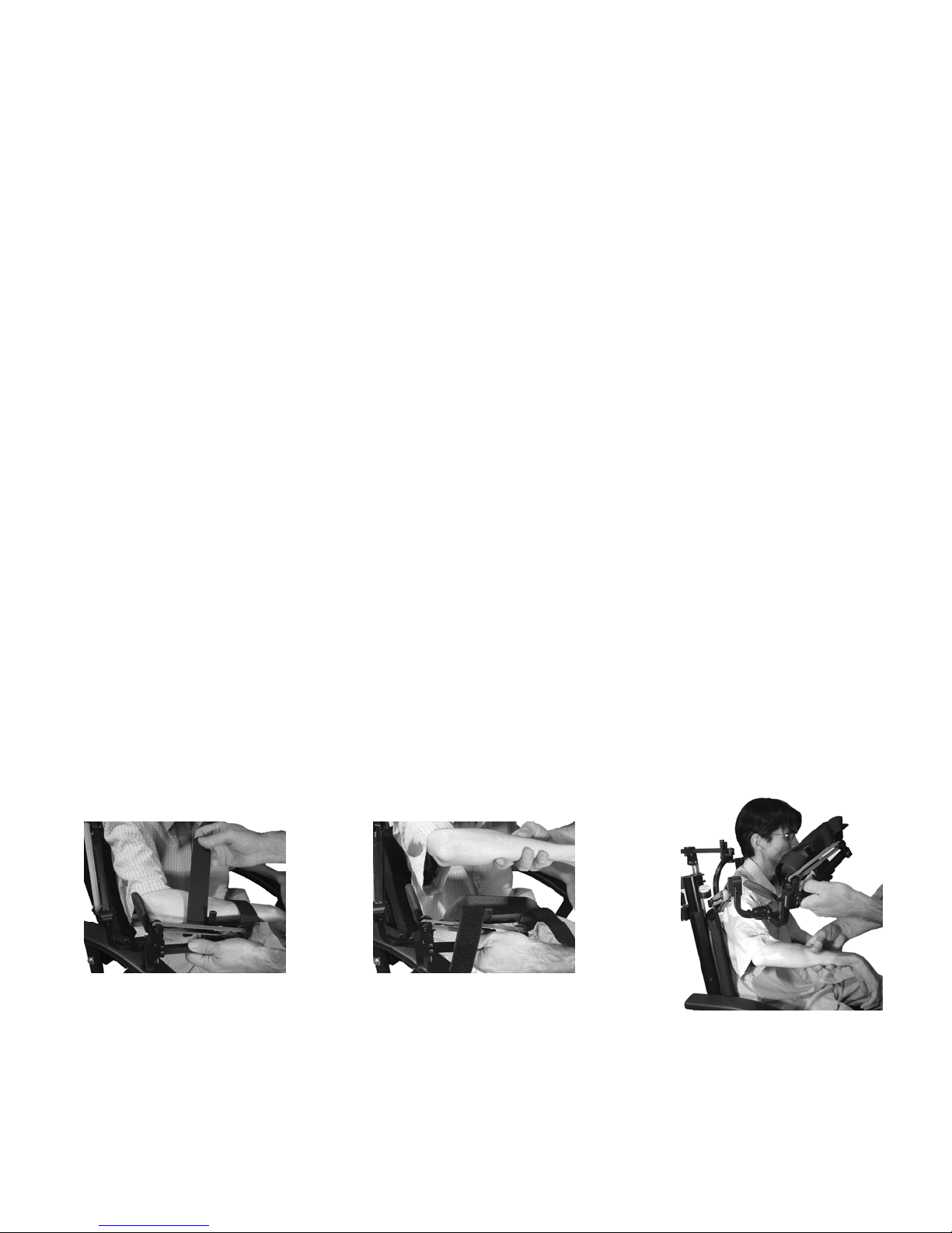
Desired Functional Outcomes of the WREX
• Ability to access face for
– Oral hygiene
– Feeding
– Washing face
– Shaving
– Wiping nose
– Adjusting glasses
– Etc.
• Ability to access environment for
– Using computer
– Handwriting
– Retrieving items from
countertop, closet, etc.
Removing the Arm from the WREX
Because the WREX operates with band tension it must carefully be handled during
arm removal to prevent injury
• Secure Forearm support with one hand holding in place
• Remove velcro straps and clients arm with the other hand
• Allow the forearm and shoulder links to return to starting position in a slow and
controlled manner
4-7
Page 33
Finalizing Setup
Check Overall Setup
• Again, observe clients shoulder and forearm to be sure they are at a comfortable,
level, resting position. (If the client is uncomfortable, WREX wear time and use
will be limited.)
• Make adjustments as necessary to achieve functional use.
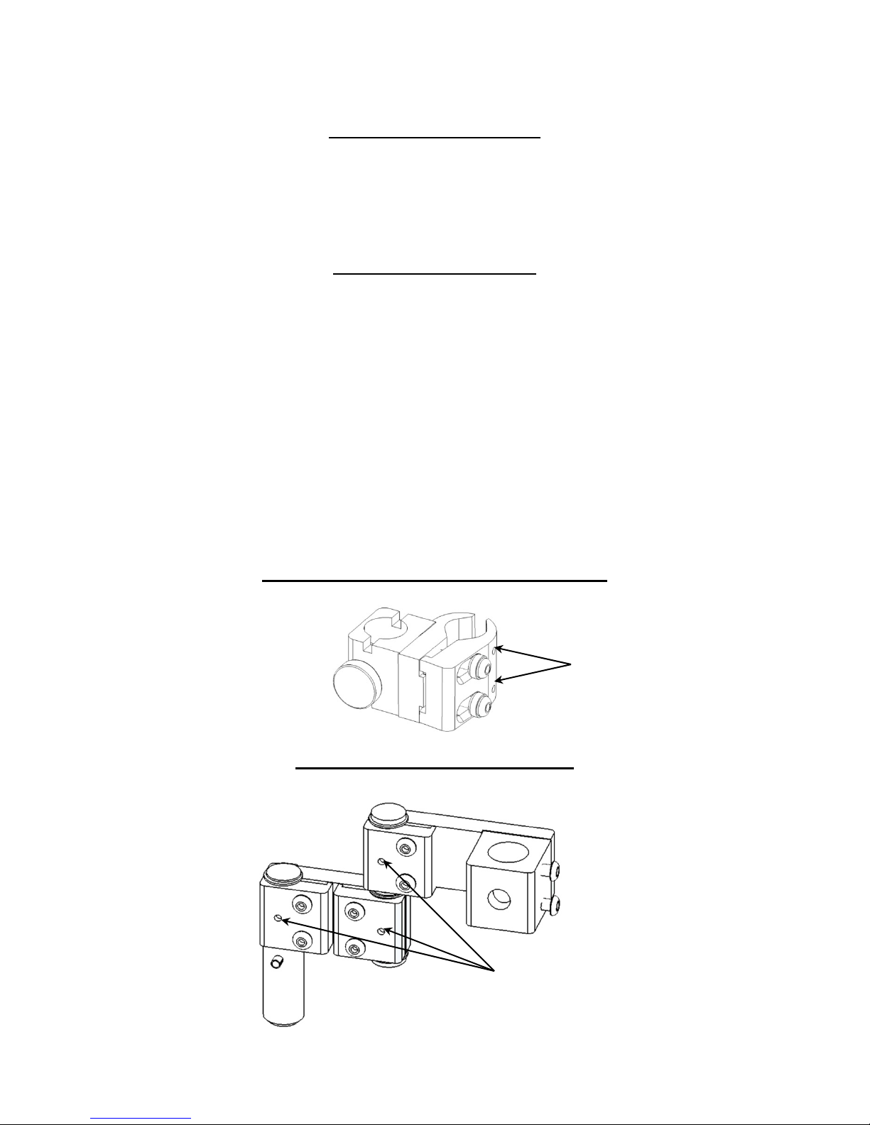
Secure the Settings
Evaluate the WREX with a variety of activities. When you and the client are
satisfied with the overall function, secure the settings.
Insure all knobs are tight.
Using the large T-Wrench insure all screws are tight.
• Using the small T-Wrench tighten the Jaw Locking Set Screws on the Mount Base
(if applicable) and the Clamp Locking Set Screws on the Mount
Arm. The pointed end of these locking set screws will pierce fabric and/or metal.
Warning: If Further adjustments are required to Mount Base or Mount Arm,
loosen these locking set screws first.
Locking the MR-10 Mount Base in Place
Jaw
Locking Set
Screws
Locking the Mount Arm in Place
Clamp
Locking Set
Screw
4-8
Page 34

WREX Product Numbers
JWREX-1-L: WREX Arm left (Forearm Support sold Separately)
JWREX-1-R: WREX Arm right (Forearm Support sold Separately)
Forearm Support Size Chart
WFS-6: Ex.Small Elbow to wrist crease length: Minimum - 6" Maximum - 7-1/2"
WFS-8: Small Elbow to wrist crease length: Minimum - 8-1/2" Maximum - 9-1/2"
WFS-9: Medium Elbow to wrist crease length: Minimum - 9-1/2" Maximum - 10-1/2"
WFS-10: Large Elbow to wrist crease length: Minimum - 10-1/2" Maximum - 12"
WFS-11: Ex.Large Elbow to wrist crease length: Minimum - 11-1/2" Maximum - 13"
WFS-1C: Custom Supply: Elbow to Wrist Crease Length & Largest Circumference of
Forearm
4-9
Page 35
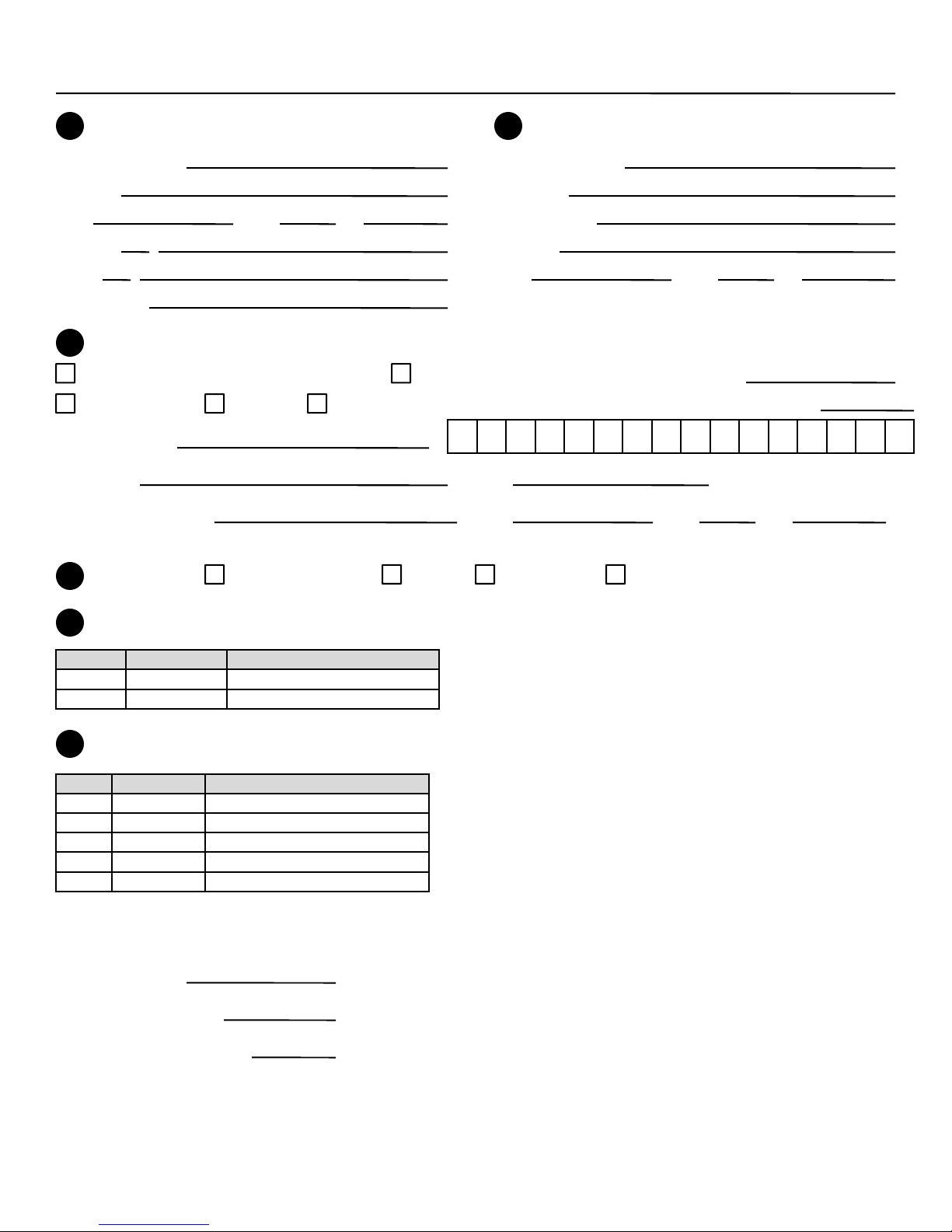
JAECO WREX Order Form
BILL TO:
1
Customer Name
Address
City State Zip
Phone ( )
Fax ( )
Your Name
3
Method of Payment:
Check (Payable to JAECO Orthopedic) Bill our Account: Purchase order Number
Credit Card: Visa MasterCard
Printed Name:
Signature: Date:
CC Billing Address City State Zip
4
Shipping:
Ground 1-5 Days 3-Day 2ndDay Air Next Day Air
Credit Card Number: Expiration date:
SHIP TO:
2
Customer Name
Attention
Department
Address
City State Zip
5
Select WREX Arm:
Qty. Product # Product Description
JWREX-1L WREX Arm Left
JWREX-1R WREX Arm Right
6
Select WREX Forearm Support:
Qty. Product # Product Description
WFS-6 6 in. Pediatric
WFS-8 8 in. Small
WFS-9 9 in. Medium
WFS-10 10 in. Large
FSC-1 Custom: Supply measurements
Custom Forearm Support Measurements
Forearm Length
Wrist Circumference
Forearm Circumference
(501) 623-5944 * Fax: (501) 623-0159 * Email: [email protected] * Web: www.jaeco-orthopedic.com
4-10
Page 36

214 Drexel
Hot Springs, AR 71901
Ph: 501-623-5944
Fax: 501-623-0159
Email: [email protected]
www.jaeco-orthopedic.com
January 18, 2007
 Loading...