

Page 1
any other appliance.
WARNING
RETAIN THIS MANUAL FOR FUTURE REFERENCE
Jade Range LLC, A Middleby Company
2650 Orbiter Ave.
Brea, CA 92821
Telephone (714) 961-2400
FAX (714) 961-2550
CHINESE RANGES
MODEL: JCR Series
INSTALLATION, OPERATION AND MAINTENANCE INSTRUCTIONS
NOTE: Instructions must be posted in a prominent location, which will instruct the user in the
event he detects the smell of gas. This information shall be obtained from your local gas
company.
Adequate clearances must be provided in front, rear and at sides of appliance for servicing.
The appliance area must be kept free and clear from combustibles.
There must be no material or obstacles obstruction the flow of combustion and ventilation air.
Improper installation, adjustment, alteration, service or
maintenance can cause property damage, injury or death.
Read the installation, operating and maintenance instructions
thoroughly before installing or serving this equipment.
WHAT TO DO IF YOU SMELL GAS
FOR YOUR SAFETY
Do not store or use gasoline
or other flammable vapors or
liquids in the vicinity of this or
• Open windows
• Do not touch electric switches
• Extinguish any open flame
•
Immediately call your gas company
P/N 24-136 REV A 7/00 Page 1
Page 2
IMPORTANT
Read these instructions before starting the installation. Upon receipt of your
equipment, thoroughly inspect it for any damage. If damage is observed, contact
your delivering agency immediately. After checking for damage, examine the
markings on the equipment to ensure that the type of gas is correct.
CLEARANCES/INSTALLATION
1. For installation with the following minimum clearances, from back and sides of
the installed appliance, to adjacent combustible or noncombustible construction:
Back
Sides
Combustible
Construction
6 inches 0 inches
9 inches 0 inches
Noncombustible
Construction
2. For installation with or without legs on noncombustible floors or curbs, or
combustible floors when using a minimum 14 ¾ inch high noncombustible stand.
INSTALLATION
A qualified installer, service agency or gas supplier must perform installation and
service.
Provisions shall be incorporated in the design of the kitchen to ensure an adequate
supply of fresh air for proper combustion.
It is suggested that for servicing and proper operation, at least 36 inches of free area
be provided to the front of the appliance.
The installation must conform with local codes, or in the absence of local codes, with
the National Fuel Gas Code, ANSIZ223.1-1988 or latest edition.
Level appliance. Adjustable legs are provided. If the appliance is equipped with
casters, the installation shall be made with connector that complies with the Standard
for Connectors for Moveable Gas appliances, ANSIZ21.69-1987 and Addenda,
Z21.69/1989, and a quick-disconnect device that complies with the standard for
Quick-Disconnect for Use With Gas Fuel, ANSIZ21.41-1989 or latest edition.
Adequate means must be provided to limit the movement of the appliance without
depending on the connector and the quick-disconnect device or its associated piping
to limit the appliance movement. The restraining means may be attached to the rear
of appliance by cable. Refer to the illustration provided on the last page.
The input rating of your equipment is for elevations up to 2,000 feet. For elevations
above 2,000 feet, the rating must be reduced 4% for each 1,000 feet above sea
level.
P/N 24-136 REV A 7/00 Page 2
Page 3

This appliance is design certified for installation in non-combustible locations only.
Minimum clearances from non-combustible construction is zero (0) inch.
Means must be provided for adequate air supply and adequate clearance for air
openings into the combustion chamber.
GAS PIPING
This appliance is provided with a regulator, set at 5” W.C. for Natural Gas or 10”
W.C. for Propane Gas
A conveniently located gas shutoff valve, external to the appliance is required for
complete shutdown.
Be sure all valves are in a closed position before connecting to gas supply.
Connect appliance to gas supply line. Under no circumstances should the gas
supply line be smaller than the inlet pipe on the appliance. Use pipe compound on
all pipe joints. Compound must be resistant to the action of liquefied petroleum
gases.
Check all gas connections for leaks using a soap and water solution. DO NOT USE
AN OPEN FLAME FOR CHECKING PURPOSES.
The appliance must be isolated from the gas supply piping system by closing its
individual manual shutoff valve during any pressure testing of the gas supply piping
system at test pressures equal to or less than ½ psig (3.45 kPa).
The appliance and its shutoff valve must be disconnected from the gas supply piping
system during and pressure testing of that system at test pressures in excess of ½
psig (3.45 kPa).
NOTE: Your appliance was tested, rated and adjusted at the factory before shipment
and should be read for use at the site without any major adjustments.
LIGHTING AND RE-LIGHTING INSTRUCTIONS
• You appliance is equipped with constant burning lighters. Lighters must be manually
lighted immediately after the gas is turned on.
• Adjustment of the lighter flames can be made through the observation openings at
the front panel. To adjust the lighter flames, use a flat screwdriver and turn the
lighter valve screw clockwise or counter-clockwise. After the desirable lighter flame
height is obtained, turn burner valves on.
• If the lighter flames go out, turn burner valves off. Wait 5 minutes and repeat above
procedure.
P/N 24-136 REV A 7/00 Page 3
Page 4

CA
UTION: USE PARTICULAR CARE TO PREVENT
OPERATION AND MAINTENANCE INSTRUCTIONS
MAINTENANCE
• Contact the factory, factory representative or a local service company to perform
maintenance and repairs.
• For daily cleaning, turn “ON” burner valves for 2 to 3 minutes and then turn “OFF.”
Use warm water and mild cleanser on top grates.
• Once a month, clean all burners with water and steel brush ensuring that all burner
ports are free of debris. Clean pilots in same manner. Once cleaned and dried, relight pilots and check for blockage. As frequently as necessary, remove grease tray,
empty and clean with mild detergent.
• The top cooling mechanism constructed of stainless tubing is provided to keep the
top surface of the range cool. This serves two main functions:
1. To maintain a cooler work area.
2. To help prevent surface warping.
• It is advisable to turn the water valve “on” when the burner valves are “on” and to
turn the water valve off when the burners are turned “off”. Allowing the water to run
for a few minutes after turning the burner valves off will cool the appliance down
rapidly.
• To prolong the life of the range top, do not leave water running overnight or when not
needed.
COLD WATER SPLASHING INTO HOT OIL.
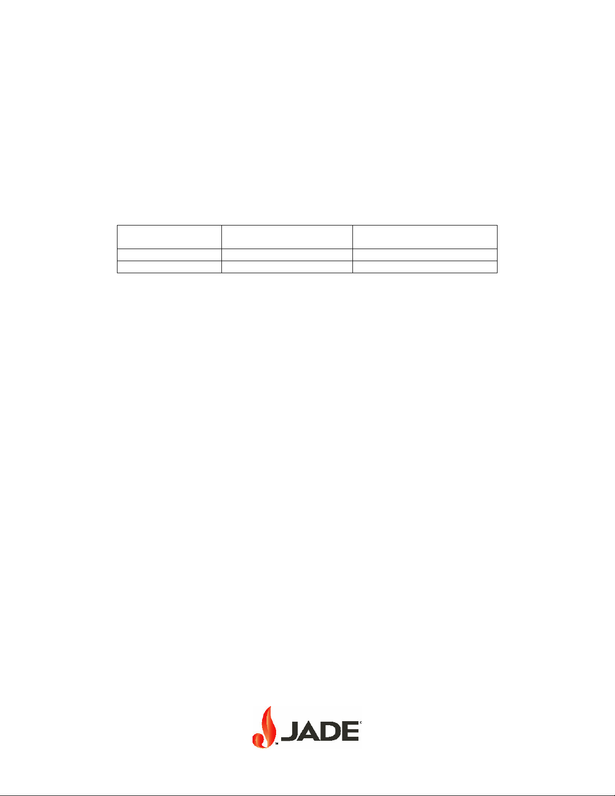
SERVICE INTERVALS
The need for servicing will, to a great extent, be determined by the appliance usage.
The following chart outlines our suggestion for service intervals:
DAYS PER WEEK SERVICE INTERVALS
Normal Use
(5 Hrs./Day)
7 60 Days 30 Days
5 to 6 120 Days 60 Days
1 to 4 180 Days 120 Days
Heavy Use
(12 Hrs./Day)
It is strongly suggested that a trained gas appliance service company examine the
appliance at least yearly.
P/N 24-136 REV A 7/00 Page 4
Page 5

REPAIR GUIDELINES
• All repair work must be completed by a licensed-trained service person experienced
in commercial gas food service equipment.
• If it becomes necessary to replace any gas control device, such as a main burner
valve or thermostat, the replacement part should be ordered from the factory only,
unless it has been determined that the EXACT part is available from your local parts
supplier.
• This appliance is serviceable to the front. It is suggested to provide at least 36
inches to the front of the appliance for servicing and for proper operation.
• When the appliance is equipped with casters, the installation shall be made with a
connector that complies with the standard for Connectors for Movable Gas
Appliances, ANSIZ21.69-1987, and Addenda, Z21.691989, and a quick-disconnect
device that complies with the Standard for Quick-Disconnect Devices for Use With
Gas Fuel, ANSIZ21.41-1989. Adequate means must be provided to limit the
movement of the appliance without depending on the connector and the quickdisconnect device or its associated piping to limit the appliance movement.
• The connector or restraining device must always be installed when the appliance is
in use. Should it become necessary to remove this device for cleaning or servicing
the appliance, be sure to reconnect this restraining device after the appliance is
returned to its originally installed position.
P/N 24-136 REV A 7/00 Page 5
Page 6

INSERT: Restraining device picture.
P/N 24-136 REV A 7/00 Page 6
 Loading...