


JADE™ Economizer Module
(MODEL W7220)
INSTALLATION INSTRUCTIONS
over is required in addition to the MA sensor. An additional
Return Air (RA) Sylkbus sensor can be added to the system
for differential enthalpy changeover.
This document describes wiring, power up, basic
troubleshooting, and common installation issues for the
JADE™ Economizer Module (Model W7220). For further
information on mounting and operation, refer to Honeywell
document 63-2700.
BEFORE INSTALLATION
Review the following before installing the The W7220:
Electrical
Rated Voltage: 20 to 30 Vac RMS; 50/60 Hz
Transformer: 100 VA maximum system input
Relay Digital Output Rating: 30 Vac
IMPORTANT
All inputs and outputs must be Class 2 wiring.
Inputs
A Mixed air (MA) analog sensor is required on all W7220
units; either an OA (Outdoor Air) sensor for dry bulb change
over or an OA Sylkbus sensor for outdoor enthalpy change
DCV (CO
) Sensor (C7232): 2-10 Vdc control signal;
2
minimum impedance >50k ohm.
Outputs
Actuator signal: 2-10 Vdc; minimum actuator impedance is
2k ohm; Sylkbus two-wire output for Honeywell Sylkbus
communicating actuators.
Exhaust fan, Y1, Y2 and AUX1 O: Contact closure (24 Vac)
All Relay Outputs (at 30 Vac):
Running: 1.5A maximum
Inrush: 7.5A maximum
When Installing This Product
1. Read these instructions carefully. Failure to follow them
could damage the product or cause a hazardous condition.
2. Check ratings given in instructions and on the product to
ensure the product is suitable for your application.
3. Installer must be a trained, experienced service technician.
4. After installation is complete, check out product operation as provided in these instructions.
Accessories
50048926-001 2-pin edge connector for sensors
(20 pieces per bag)
50048926-002 6-pin edge connector for field wiring
(20 pieces per bag)
C7250 20k sensor for MA or OA (dry bulb changeover)
C7400S Sylkbus sensor for enthalpy control in OA and/or RA
and RA for differential dry bulb changeover
W7220 PCMOD interface tool for JADE controller and Per-
sonal Computer. Go to www.customer.honeywell.com/
economizertools for the software
50053060-001 Duct mounting kit for sensors
62-0331-07

JADE™ ECONOMIZER MODULE
WARNING
CAUTION
INSTALLATION AND SETUP
The Economizer module may be mounted in any orientation.
However, mounting in the orientation shown above permits
proper viewing of the LCD display and use of the keypad.
NOTE: Jade will be in the "set up" mode for the first 60
minutes after powered. If a sensor for OA air or
Sylkbus device (sensor, actuator) is disconnected during the set up mode, the Jade will not
alarm that failure. The MA sensor is a system
"critical" sensor; if the MA sensor is removed
during the set up mode, the Jade will alarm. After
60 minutes the Jade controller will change to
operation mode and all components removed or
failed will alarm in the operation mode.
WIRING
All wiring must comply with applicable electrical codes and
ordinances, or as specified on installation wiring diagrams.
Module wiring in the field is terminated to the four screw
terminal blocks located on the left and right sides.
Module wiring at the OEM factory is terminated via the header
pin terminals located on the left and right sides. The header
terminal pins and the terminal blocks have common
terminations for the appropriate input or output. The part
number for the OEM female mating connector is 0039973997.
Electrical Shock Hazard.
Can cause severe injury, death or property
damage.
Disconnect power supply before beginning wiring, or
making wiring connections, to prevent electrical shock
or equipment damage.
Equipment Damage Hazard.
Electrostatic discharge can short equipment
circuitry.
Ensure that you are properly grounded before
handling the unit.
Each terminal can accommodate the following gauges of wire:
• Single wire – from 18 AWG to 22 AWG solid or stranded
• Multiple wires – up to two 22 AWG stranded
• For the 24 Vac connections: single wire – from 14 to 18
AWG solid or stranded
For S-BUS wiring, the sensors may be mounted up to 200 ft.
(61 m) from the JADE controller. When the length of wire is
over 100 feet use twisted pair shielded wire.
NOTE: All wiring is polarity insensitive.
Refer to Fig. 1 through Fig. 6 for common wiring
configurations.
Actuator Wiring Options:
1. The JADE economizer controller can only have one (1)
communicating actuator connected to it.
2. Up to four (4) non-communicating and (2) 2-position
actuators (1 each on EXH1 and AUX1 O)
3. One (1) communicating and up to four (4) non-communicating and (2) 2-position actuators (1 each on EXH1
and AUX1 O)
When using a 2-position actuator on the AUX1 O the AUX1 O
must be programmed for Exh2 and the % open is the % open
of the outdoor damper when the 2-pos actuator opens.
Connect 24 V to Exh1 and/or AUX1 O and ground to the Jade
"C" terminal.
62-0331—07 2
JADE™ ECONOMIZER MODULE
ROOF TOP UNIT
Y1O
Y2O
Y1I
Y2I
OCC
24 VAC
1K1
1K1
E-GND
Y1
G
W2
W1
Y2
O/B
OCC
W7220 ECONOMIZER CONTROLLER MODULE
THERMOSTAT
CO2
SENSOR
2-10 VDC
(OPTIONAL)
MA
MA
OAT
OAT
C R
M28980B
IAQ (2-10V)
IAQ COM
IAQ 24V
ACT (2-10V)
ACT COM
ACT 24V
AUX1-0
AUX2-I
OA TEMP
SENSOR
20K NTC
M7215
(OPTIONAL COMMUNICATING DCA)
NOTE THAT THE C7250 20K NTC SENSOR CAN BE MOUNTED IN THE OAT ONLY IN THIS CONFIGURATION.
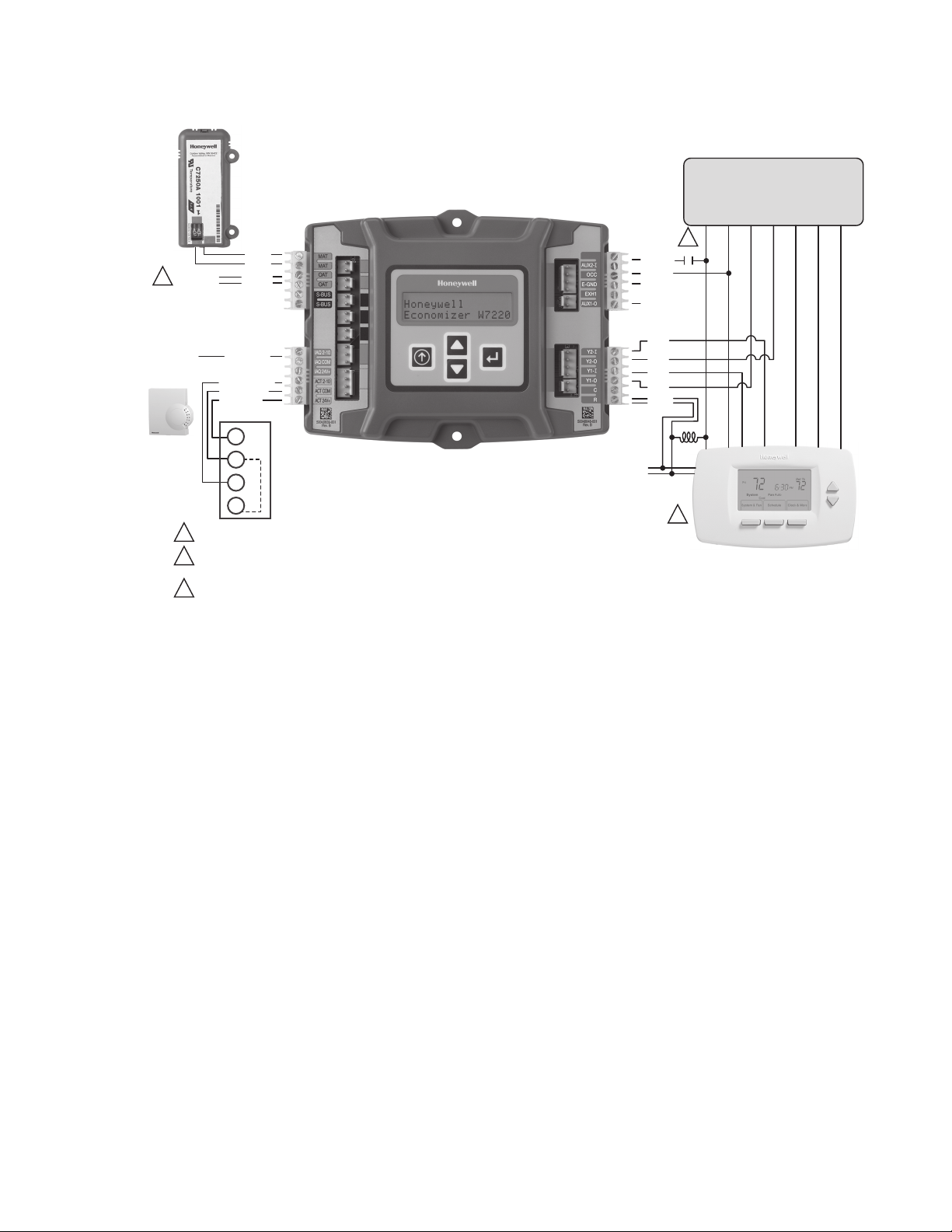
1
WHEN USING A HEAT PUMP THERMOSTAT OR A PROGRAMMABLE THERMOSTAT, THERMOSTAT TERMINALS
MAY DIFFER: W1 MAY BE LABELED O OR B AND W2 MAY BE LABELED W.
WHEN USING A HEAT PUMP WITH DEFROST FEEDBACK, ADD AN ISOLATION RELAY BETWEEN O AND C.
2
3
3
1
MA TEMP
SENSOR
20K NTC
+
-
TR1
TR
IN
IN
2
R(+)
C(-)
Fig. 1. Stand-alone dry bulb Economizer configuration with black motor M7215.
3 62-0331—07
JADE™ ECONOMIZER MODULE
ROOF TOP UNIT
Y1O
Y2O
Y1I
Y2I
OCC
24 VAC
E-GND
Y1
G
W2
W1
Y2
O/B
OCC
W7220 ECONOMIZER CONTROLLER MODULE
THERMOSTAT
CO2
SENSOR
2-10 VDC
(OPTIONAL)
MA
MA
OA
OA
C R
R(+)
C(-)
M32650B
IAQ (2-10V)
IAQ COM
IAQ 24V
ACT (2-10V)
ACT COM
ACT 24V
3
1
2
OA TEMP
SENSOR
20K NTC
MS3103J
OR MS3105J
1
1
MA TEMP
SENSOR
20K NTC
S-BUS
4
5
S-BUS
AUX1-0
AUX2-I
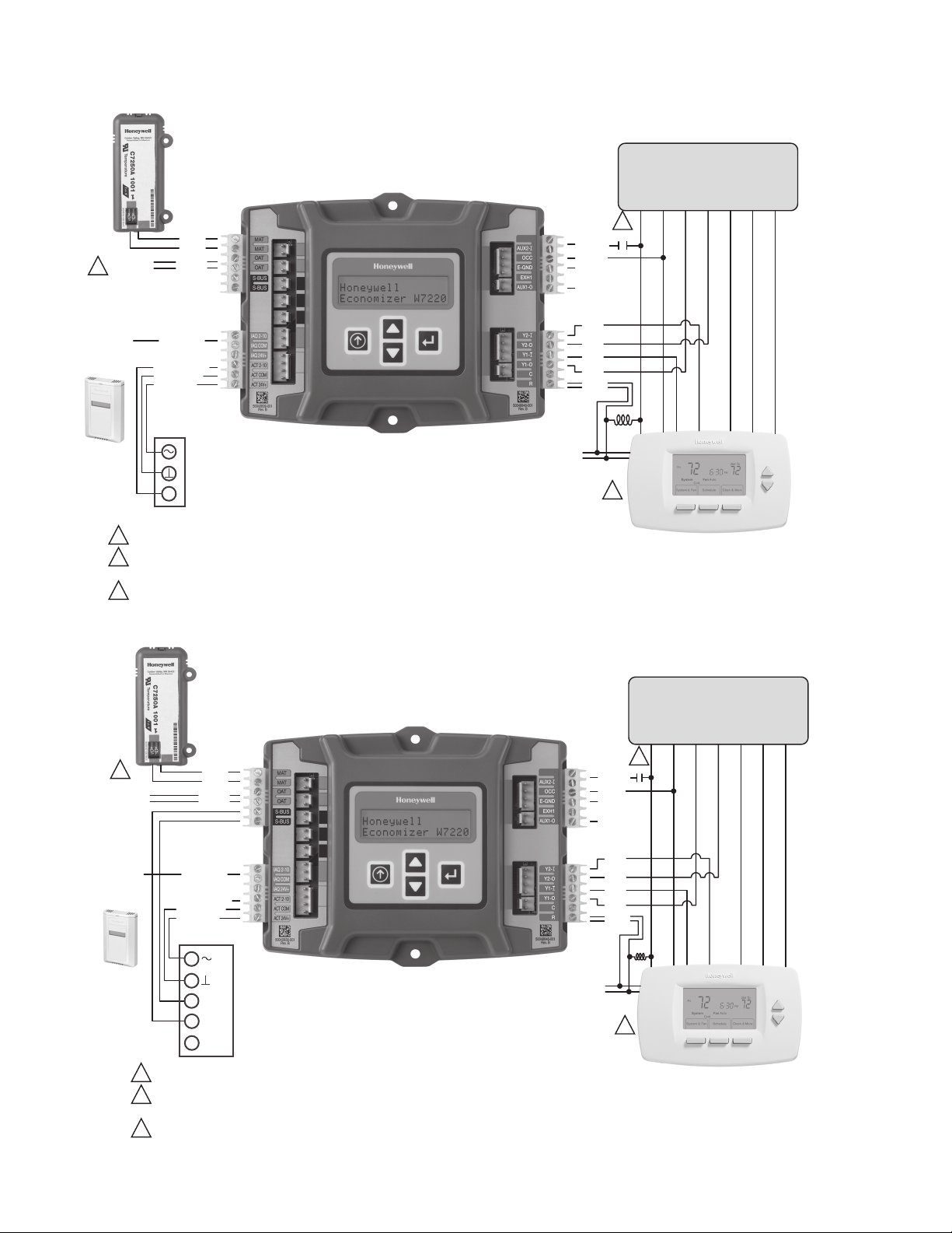
NOTE THAT THE 20K NTC SENSOR CAN BE MOUNTED IN THE OA TERMINALS ONLY IN THIS CONFIGURATION.
WHEN USING A HEAT PUMP THERMOSTAT OR A PROGRAMMABLE THERMOSTAT, THERMOSTAT TERMINALS
MAY DIFFER: W1 MAY BE LABELED O OR B AND W2 MAY BE LABELED W.
WHEN USING A HEAT PUMP WITH DEFROST FEEDBACK, ADD AN ISOLATION RELAY BETWEEN O AND C.
2
2
3
3
1K1
1K1
O/B
ROOF TOP UNIT
Y1
OCC
THERMOSTAT
W1
Y2
OA TEMP
1
SENSOR
20K NTC
CO2
SENSOR
2-10 VDC
(OPTIONAL)
1
2
3
MA TEMP
SENSOR
20K NTC
MA
MA
OA
OA
IAQ (2-10V)
IAQ COM
IAQ 24V
ACT (2-10V)
ACT COM
ACT 24V
MS7503 OR MS7505
3
NOTE THAT THE 20K NTC SENSOR CAN BE MOUNTED IN THE OA TERMINALS ONLY IN THIS CONFIGURATION.
WHEN USING A HEAT PUMP THERMOSTAT OR A PROGRAMMABLE THERMOSTAT, THERMOSTAT TERMINALS
MAY DIFFER: W1 MAY BE LABELED O OR B AND W2 MAY BE LABELED W.
WHEN USING A HEAT PUMP WITH DEFROST FEEDBACK, ADD AN ISOLATION RELAY BETWEEN O AND C.
W7220 ECONOMIZER CONTROLLER MODULE
24 VAC
AUX2-I
OCC
E-GND
AUX1-0
Y2I
Y2O
Y1I
Y1O
C R
R(+)
C(-)
2
3
1K1
1K1
Fig. 2. Stand-alone dry-bulb Economizer configuration with Honeywell MS7403 Direct Coupled Actuator.
G
W2
M32564B
Fig. 3. Stand-alone dry-bulb Economizer configuration with Honeywell MS3103J or MS3105J communicating actuators.
62-0331—07 4

JADE™ ECONOMIZER MODULE
CO2
SENSOR
2-10 VDC
(OPTIONAL)
1
MA TEMP
SENSOR
20K NTC
MA
MA
S-BUS
S-BUS
IAQ (2-10V)
IAQ COM
IAQ 24V
ACT (2-10V)
ACT COM
ACT 24V
TR
TR1
IN
+
IN
-
2
W7220 ECONOMIZER CONTROLLER MODULE
M7215
OUTSIDE AIR
TEMP/HUMIDITY (ENTHALPY)
SYLKBUS SENSOR
RETURN AIR
TEMP/HUMIDITY (ENTHALPY)
SYLKBUS SENSOR
ROOF TOP UNIT
O/B
OCC
Y1
W1
Y2
4
1K1
AUX2-I
OCC
E-GND
AUX1-0
Y2I
Y2O
Y1I
Y1O
1K1
C R
R(+)
24 VAC
C(-)
3
THERMOSTAT
IN THIS CONFIGURATION, AN OPTIONAL DISCHARGE AIR TEMP/HUMIDITY
1
(ENTHALPY) SYLKBUS SENSOR CAN BE ADDED FOR ADVANCED
CONTROL AS SHOWN IN THE LOWER LEFT OF THIS FIGURE.
DO NOT USE THE C7250 20K NTC SENSOR WITH THE OA TERMINAL IN THIS
2
CONFIGURATION.
3
WHEN USING A HEAT PUMP THERMOSTAT OR A PROGRAMMABLE THERMOSTAT,
THERMOSTAT TERMINALS MAY DIFFER: W1 MAY BE LABELED O OR B AND W2
MAY BE LABELED W.
4
WHEN USING A HEAT PUMP WITH DEFROST FEEDBACK, ADD AN ISOLATION
RELAY BETWEEN O AND C.
G
W2
M32565B
Fig. 4. Economizer with Sylk Bus sensors for enthalpy configuration with Honeywell M7215 black motor.
5 62-0331—07

JADE™ ECONOMIZER MODULE
OUTSIDE AIR
TEMP/HUMIDITY (ENTHALPY)
SYLKBUS SENSOR
RETURN AIR
TEMP/HUMIDITY (ENTHALPY)
SYLKBUS SENSOR
ROOF TOP UNIT
Y1O
Y2O
Y1I
Y2I
OCC
E-GND
Y1
G
W2
W1
Y2
O/B
OCC
W7220 ECONOMIZER CONTROLLER MODULE
THERMOSTAT
C R
R(+)
C(-)
M32566B
IN THIS CONFIGURATION, AN OPTIONAL DISCHARGE AIR TEMP/HUMIDITY
(ENTHALPY) SYLKBUS SENSOR CAN BE ADDED FOR ADVANCED
CONTROL AS SHOWN IN THE LOWER LEFT OF THIS FIGURE.
DO NOT USE THE C7250 20K NTC SENSOR WITH THE OA TERMINAL IN THIS
CONFIGURATION.
WHEN USING A HEAT PUMP THERMOSTAT OR A PROGRAMMABLE THERMOSTAT,
THERMOSTAT TERMINALS MAY DIFFER: W1 MAY BE LABELED O OR B AND W2
MAY BE LABELED W.
WHEN USING A HEAT PUMP WITH DEFROST FEEDBACK, ADD AN ISOLATION
RELAY BETWEEN O AND C.
1
1
2
MS7503 OR MS7505
3
S-BUS
S-BUS
MA
MA
CO2
SENSOR
2-10 VDC
(OPTIONAL)
IAQ (2-10V)
IAQ COM
IAQ 24V
ACT (2-10V)
ACT COM
ACT 24V
MA TEMP
SENSOR
20K NTC
AUX1-0
AUX2-I
2
3
4
3
4
1K1
1K1
24 VAC
Fig. 5. Economizer with Sylk Bus sensors for enthalpy configuration with a Honeywell MS7505 or MS7503 Direct
62-0331—07 6
Coupled Actuator.

JADE™ ECONOMIZER MODULE
C7400S
OUTSIDE AIR
TEMP/HUMIDITY (ENTHALPY)
SYLKBUS SENSOR
C7400S
RETURN AIR
TEMP/HUMIDITY (ENTHALPY)
SYLKBUS SENSOR
ROOF TOP UNIT
Y1O
Y2O
Y1I
Y2I
OCC
E-GND
Y1
G
W2
W1
Y2
O/B
OCC
W7220 ECONOMIZER CONTROLLER MODULE
THERMOSTAT
C R
C(-)
M32653B
IN THIS CONFIGURATION, AN OPTIONAL DISCHARGE AIR TEM/HUMIDITY
(ENTHALPY) SYLKBUS SENSOR CAN BE ADDED FOR ADVANCED
CONTROL AS SHOWN IN THE LOWER LEFT OF THIS FIGURE.
1
1
THE S-BUS COMPONENTS MAY BE DAISY CHAINED TO ANOTHER S-BUS
COMPONENT.
WHEN USING A HEAT PUMP THERMOSTAT OR A PROGRAMMABLE
THERMOSTAT, THERMOSTAT TERMINALS MAY DIFFER: W1 MAY BE
LABELED O OR B AND W2 MAY BE LABELED W.
WHEN USING A HEAT PUMP WITH DEFROST FEEDBACK, ADD AN
ISOLATION RELAY BETWEEN O AND C.
2
S-BUS
S-BUS
MA
MA
CO2
SENSOR
2-10 VDC
(OPTIONAL)
IAQ (2-10V)
IAQ COM
IAQ 24V
ACT (2-10V)
ACT COM
ACT 24V
MA TEMP
SENSOR
20K NTC
AUX1-0
AUX2-I
3
1
2
MS3103J
OR MS3105J
S-BUS
4
5
S-BUS
2
R(+)
24 VAC
3
3
4
4
1K1
1K1
1
2
ACTUATOR
EXH1 OR AUX1 O
NOTE: ON/OFF ACTUATORS CAN BE USED ON THE EXH1 OR AUX1
O TERMINAL WITH GROUND TO THE C TERMINAL. WHEN
PROGRAMMING THE EXH1 OR AUX1 O, THE % IS THE PERCENT
OPEN POSITION OF THE OUTDOOR AIR DAMPER WHEN THE
EXH1 OR AUX1 O TERMINAL IS ENERGIZED AND THE 2-POS
DAMPER GOES OPEN. IF USING THE AUX1 O TERMINAL
PROGRAM AUX1 O FOR EXH2.
C
M33409
V
Fig. 6. Economizer with Sylk bus sensor for enthalpy configuration with Honeywell MS3103 or MS3105 communicating
actuators.
Fig. 7. 2-position actuator.
7 62-0331—07

JADE™ ECONOMIZER MODULE
ECONOMIZING
AVAILABLE
NOT AVAILABLE
TEMPERATURE
ENTHALPY
H
A
R
RA TEMP
)
H
R
%
(
M
U
ABSOLUTE HUMIDITY
DUAL ENTHALPY
SINGLE ENTHALPY
P2 (T,RH)
ES4 ES3 ES2 ES1 HL
ES5
HIGH LIMIT
P1
(T,RH)
Fig. 8. Single Enthalpy curves and boundaries.
Table 1. Single Enthalpy and Dual Enthalpy High Limit Curves.
Enthalpy
Curve
Tem p.
Dry-Bulb (°F)
Temp.
Dewpoint (°F)
Enthalpy
(btu/lb/da)
Temp. °F Humidity %RH Temp. °F Humidity %RH
Point P1 Point P2
ES1 80.0 60.0 28.0 80.0 36.8 66.3 80.1
ES2 75.0 57.0 26.0 75.0 39.6 63.3 80.0
ES3 70.0 54.0 24.0 70.0 42.3 59.7 81.4
ES4 65.0 51.0 22.0 65.0 44.8 55.7 84.2
ES5 60.0 48.0 20.0 60.0 46.9 51.3 88.5
HL 86.0 66.0 32.4 86.0 38.9 72.4 80.3
M32286
Power Up
After the module is mounted and wired, apply power.
Power Up Delay
Upon power up (or after a power outage or brownout), the
W7220 controller module begins a 5 minute power up delay
before enabling mechanical cooling.
Initial Menu Display
On initial start up, Honeywell displays on the first line and
Economizer W7220 on the second line. After a brief pause,
the revision of the software appears on the first line and the
second line will be blank.
Power Loss (Outage or Brownout)
All setpoints and advanced settings are restoreda after any
power loss or interruption.
NOTE: If power goes below 18 Vac, the W7220 controller
module assumes a power loss and the 5 minute
power up delay will become functional when
power returns above 18 Vac.
TROUBLESHOOTING
Alarms
The Economizer module provides alarm messages that
display on the 2-line LCD.
NOTE: Upon power up, the module waits several sec-
You can also navigate to the Alarms menu at any time.
a
All settings are stored in non-volatile flash memory.
onds before checking for alarms. This allows
time for all the configured devices (e.g. sensors,
actuator) to become operational. If one or more
alarms are present and there has been no keypad
activity for at least 5 minutes, the Alarms menu
displays and cycles through the active alarms.
62-0331—07 8

JADE™ ECONOMIZER MODULE
Table 2. Alarms Menu.
Menu Alarm
ALARMS(_) MA T SENS ERR
CO2 SENS ERR
OA T SENS ERR
DA ENTHL ERR
SYS ALARM
ACT Over Voltage
ACT Under Voltage
ACT Stalled
a
b
b
b
NOTES:
1. The Alarms menu displays only when alarm(s)
are active and includes the number of active
alarms in parenthesis ().
2. The alarms listed are a few examples. Additional
alarms display depending on the parameter settings and configuration.
a
When AUX1 O is set to SYS and there is any alarm (e.g., failed sensors,
etc.), the AUX1 O terminal has 24 Vac out and the LCD displays the
ALARM.
b
This alarm is only displayed when a communicating actuator is used. (ex:
MS3105AJ)
To clear an alarm, perform the following:
1. Navigate to the desired alarm.
2. Press the
↵ button.
3. ERASE? displays.
4. Press the ↵ button.
5. ALARM ERASED displays.
6. Press the button (MenuUp/Exit) to complete the
action and return to the previous menu.
NOTE: If an alarm still exists after you clear it, it re-dis-
plays within 5 seconds.
NOTE: Jade will be in the "set up" mode for the first 60
minutes after powered. If a sensor for OA air or
Sylkbus device (sensor, actuator) is disconnected during the set up mode, the Jade will not
alarm that failure. The MA sensor is a system
"critical" sensor; if the MA sensor is removed
during the set up mode, the Jade will alarm. After
60 minutes the Jade controller will change to
operation mode and all components removed or
failed will alarm in the operation mode.
Clearing Alarms
Once the alarm has been identified and the cause has been
removed (e.g. replaced faulty sensor), the alarm can be
cleared from the display.
9 62-0331—07

JADE™ ECONOMIZER MODULE
COMMON INSTALLATION ISSUES AND CONCERNS
Table 3. Installation Issues and Concerns.
Area Issue or Concern Possible Cause and Remedy
Configuration Are the old sensors in the unit
(C7400A, C7150 or C7232)
compatible with the economizer
controller?
The unit has a W7459
economizer and black motor.
Do I need to change the motor?
Wiring I have 4 terminals on my
actuator and the wiring only
shows 3 wires.
There is an Earth Ground
terminal. Do I need to wire to
earth ground?
What are the part numbers of
the 2 and 6 pin side
connectors?
No, the C7400A and C7150 sensors are not compatible with the W7220. The enthalpy sensor
for the W7220 is the C7400S. The Mixed Air or Outdoor air dry bulb sensors are the C7250A.
The C7232 CO
If you have a W7459 economizer with a M7415 motor you will need to change to a M7215
motor. The W7220 has a 2 to 10 Vdc out to the motor, so you will need a M7215 motor. The
M7215 motors are used with the W7212 economizers. So if you have one of these units, you
will not have to change the motor.
The economizer 24 Vac COM can be wired to the Honeywell actuator common ( or
TR1). The actuators have internal ground circuits.
Yes, the economizer must be wired to earth ground.
The 2-pin connectors are Honeywell part number 50048926-001 and the 6-pin connectors
are Honeywell part number 50048926-002. Both are available in accessory bags of 20 each.
sensor is compatible with the W7220.
2
62-0331—07 10

Table 3. Installation Issues and Concerns. (Continued)
Area Issue or Concern Possible Cause and Remedy
Operation or Use My outdoor temperature
reading on the STATUS menu is
Check the sensor wiring. Enthalpy sensors are to be wired to the Sylk Bus terminals.
Temperature sensors are to be wired to the OAT and MAT terminals.
not accurate.
If my enthalpy sensor drifts in
accuracy over time, can I recalibrate it?
Can I go back to factory
The sensors are not able to be re-calibrated in the field. However there is a menu item under
the ADVANCED menu where you are able to input a limited offset in temperature and
humidity for each sensor you have connected to the economizer.
Under the SYSTEM SETUP menu you can change the setpoints to the factory defaults.
defaults and start over?
Will I be able to see the LCD
The LCD screen has a backlight that is always illuminated.
screen when it is in the unit?
What is a good setpoint for the
Mixed Air Temperature (MAT)?
The mixed air temperature is the temperature of air that you want to supply to the space. In a
commercial building, this is between 50 to 55°F (10 to 13°C). The mixed air is the mixing of
the return air and the outdoor air.
I am using enthalpy sensors.
Why did the control ask me to
In the event the humidity sensor in the enthalpy sensors fails, the backup algorithm in the
control is to default to the temperature sensor in the enthalpy sensor.
input a dry bulb changeover
temperature?
In checkout, the outdoor
damper closes when I
Check the actuator linkage or rotation. In the CHECKOUT mode, the outdoor damper should
drive open or closed with the return air damper having the opposite effect.
command it open.
How do I set my minimum
position?
The minimum position is set using the VENTMIN and VENTMAX setup in the SETPOINTS
menu. VENTMIN is the minimum ventilation required when using an occupancy sensor and
VENTMAX is the minimum ventilation when not using an occupancy sensor for Demand
Control Ventilation. The VENTMAX position is set the same as with the potentiometer on the
analog economizers and is the output voltage to the damper actuator. The range is 2 Vdc
closed OA damper and 10 Vdc open OA damper.
What if my damper does not go
Check the damper linkage or hub to make sure the damper is able to close completely.
completely closed in the
checkout operation?
How do I set the OCC? There are two settings for the OCC setting, INPUT and ALWAYS. INPUT is from the space
thermostat, if it has an occupancy output. ALWAYS is the unit in the occupied mode, if the
economizer is powered (fan on).
Does the economizer save my
program values if the unit loses
Yes, once the changes are stored in the controller they will be stored until they are changed
by the operator.
power?
If the unit is left in checkout,
The unit will remain in checkout for 10 minutes, then return to normal operation.
how long will the unit stay in
checkout mode without input?
JADE™ ECONOMIZER MODULE
11 62-0331—07

JADE™ ECONOMIZER MODULE
Automation and Control Solutions
Honeywell International Inc.
1985 Douglas Drive North
Golden Valley, MN 55422
customer.honeywell.com
® U.S. Registered Trademark
© 2012 Honeywell International Inc.
62-0331—07 M.S. Rev. 02-12
Printed in United States
 Loading...