

Jade RJGR Installation Instructions Manual
INSTALLATION INSTRUCTIONS
JADE GAS RANGE
MODEL RJGR
PLEASE READ THIS MANUAL COMPLETELY AND CAREFULLY BEFORE PROCEEDING.
IMPORTANT: Save these instructions for local inspector’s use.
IMPORTANT: Observe all governing codes and ordinances.
NOTE TO THE INSTALLER: Please leave this manual with the range for the consumer.
NOTE TO THE CONSUMER: Please retain this manual for future reference.
IMPORTANT
The installation of this range must conform with local codes or, in the absence of local
codes, with the National Fuel Gas Code ANSI Z223.1 - latest edition. If installed in
Canada, installation must conform with local codes, or with CAN/CGA B149.1, Natural
Gas Installation Code or CAN/CGA B149.2 Propane Gas Installation Code.
This appliance must be electrically grounded in accordance with local codes or, in the
absence of local codes, with the National Electrical Code, ANSI/NFA 70- latest edition.
In Canada, it must be electrically grounded in accordance with local codes or with CSA
C22.1 Canadian Electrical Code Part 1.
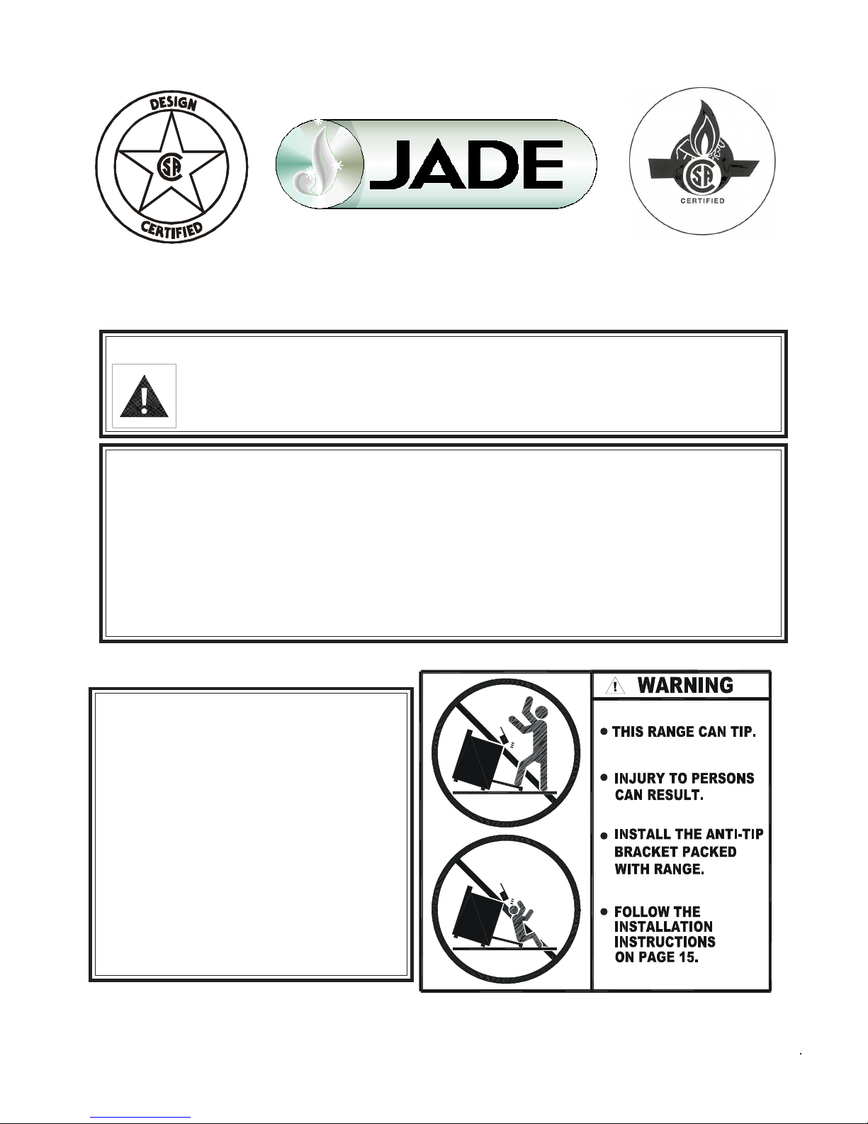
WARNING: If the information in this manual is not followed
exactly, a fire or explosion may result causing property damage, personal injury or death.
• Do not store or use gasoline or other flammable vapors
and liquids in the vicinity of this or any other appliance.
WHAT TO DO IF YOU SMELL GAS
• Do not try to light any appliance.
• Do not touch any electrical switch; do not use any phone
in the building.
• Immediately call your gas supplier from a neighbor’s
phone. Follow the gas supplier’s instructions.
• If you cannot reach your gas supplier, call the fire
department.
• Installation and service must be performed by a qualified
installer, service agency or the gas supplier.
7355 E. SLAUSON AVENUE, COMMERCE, CALIFORNIA 90040 (323) 889-4888 Fax: (323) 889-4890
P/N 2400030000 06/03
MADE IN USA
1
IMPORTANT SAFETY INSTRUCTIONS
CONTENTS PAGE
Important Safety Instructions............................................................... 1-2
Unpacking and Inspection................................................................... 2
Range Specifications........................................................................... 3
Legs Installation.................................................................................. 3
Casters Installation.............................................................................. 4
Curb Base Installation......................................................................... 5
Stub Back Installation......................................................................... 6
Clearances Against Combustible Surfaces......................................... 7
Gas Connection.................................................................................. 8
Gas Conversion For RJGR Series .................................................. 9-10
Electrical Connection.......................................................................... 11
Initial Start-up and Burner Adjustment
Open top / Simmer ................................................................ 12
Infrared Broiler....................................................................... 13
Oven...................................................................................... 13
Wok........................................................................................ 14
Charbroiler.............................................................................. 14
Griddle.................................................................................... 14
Installation of Anti-Tip Bracket............................................... 15-16
If the range is to be installed on an area covered with
linoleum or any other floor covering, make sure that
the floor covering can withstand 90°F (65°C) above
room temperature without warping, shrinking or discoloring. Do not install the range over carpeting.
UNPACKING AND INSPECTION:
Check that the container is upright. Check for visible
damages on the carton. If there is damage to the carton, contact the carrier, and request an inspection. Do
not refuse shipment but file the appropriate freight
claims. Responsibility for shipping damage is with the
carrier and dealer or end user.
Cut the shipping straps and carefully lift the carton up
from the range. Check the range for visible damage.
Do not use this range as a supplement to your furnace/
heater. It is not designed to heat up the kitchen nor
any other room. Using this appliance other than its
intended use could be dangerous.
Remove, unwrap and temporarily lay aside any part or
accessory shipped with the unit and make sure that
there are no hardware or accessories left in the box for
accidental disposal. Make sure all packing material
and literature are removed from the oven before
connecting gas and electrical supply to the range.
2
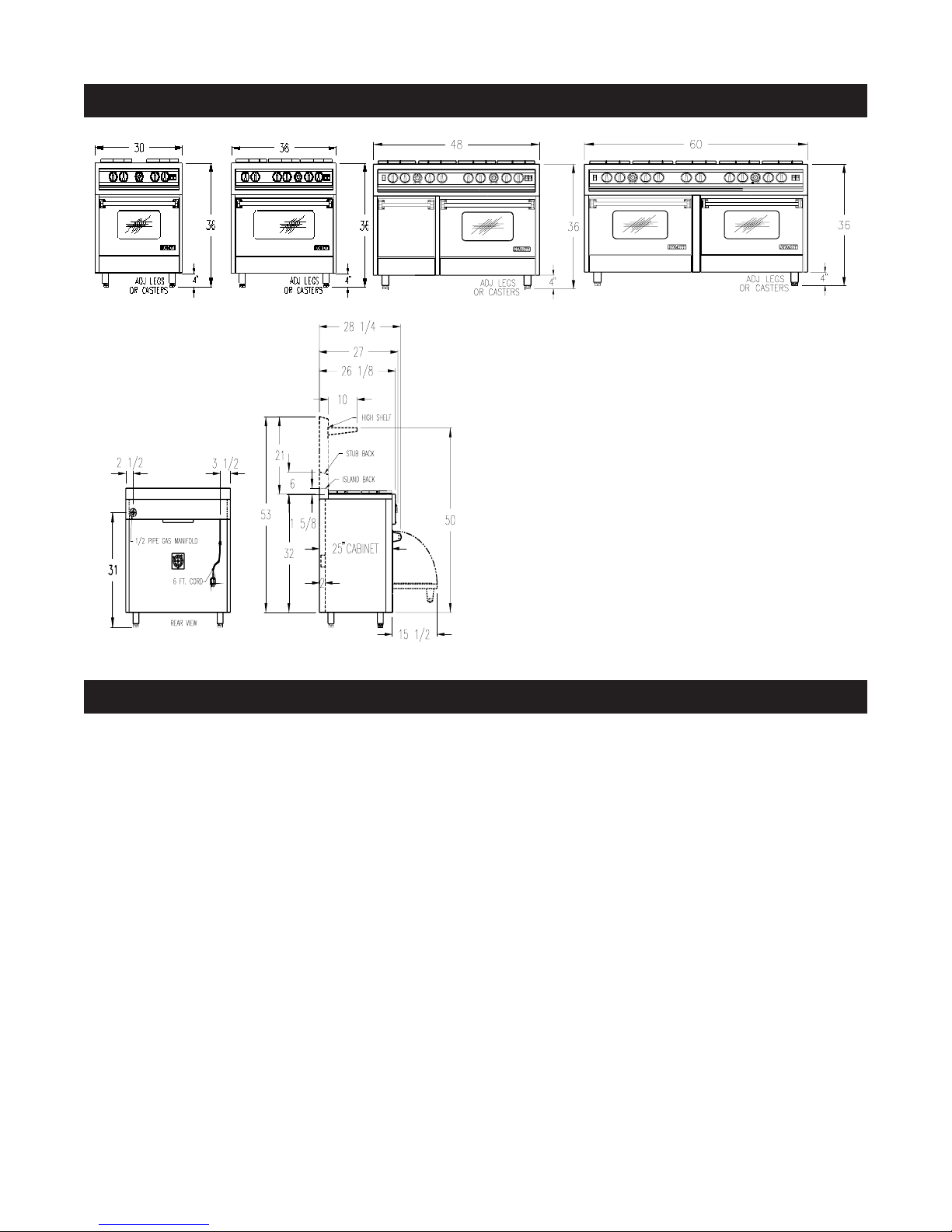
RANGE SPECIFICATIONS
MODEL: RJGR - 30 MODEL: RJGR - 36 MODEL: RJGR - 48 MODEL: RJGR - 60
TYPICAL FOR ALL MODELS
LEGS INSTALLATION
The stainless steel legs are wrapped and packed separately in the oven. The legs must be installed near
where the range is to be used to avoid pushing or sliding the range that could cause damage to the legs and
to the floor covering. To install the legs it is strongly
recommended that a lift jack be used to lift the range
completely. Then screw the legs tightly to the bottom
of the range. The distance between the top of the range
(not including the cast iron grates) to the floor must be
at least 36 inches. The legs can be adjusted up to 2
inches higher by turning the stainless steel adjustable
feet using a 1” open end or adjustable wrench. Adjust
the legs so that the top of the range is even or higher
than the counter top.
IMPORTANT:
NEVER SET THE RANGE LOWER THAN THE
COUNTER TOP. THE HEAT FROM THE TOP BURNERS CAN DAMAGE THE COUNTER TOP.
For proper baking results, it is important that the range
is leveled. To level the range:
1. Use a 1” open end or adjustable wrench. Turn the
adjustable feet equally until the top of the range is even
or higher than the counter top.
2. Install the oven racks.
3. Put a spirit level or a glass measuring cup partially
filled with water on one of the oven racks.
4. Adjust the legs’ feet using the wrench.
3

CASTERS INSTALLATION:
Casters are used for easy access in servicing or cleaning the appliance. However, unlike the legs, casters
are not adjustable. Any adjustment needed for leveling the range is accomplished by placing shims on the
floor. When checking to see if the range is level, always use a spirit level or glass measuring cup placed
on one of the racks. It is extremely important for proper
baking results that the racks are leveled.
When installing casters, it is strongly recommended
that a lift jack be used to lift the range completely.
Install the two casters without brakes to the rear. Install the two casters with brakes to the front for accessibility.
After the range is set and leveled on its final location,
set the caster brakes on to prevent movement of the
range under normal use.
IMPORTANT: The top of the range must be even or
higher than the counter top. The heat from the top burners can damage the counter top.
When the appliance is installed with casters, it must be
installed with the casters supplied, a connector complying with ANSI Z21.69 and a quick disconnect device complying with ANSI Z21.41. It must also be installed with restraining means to guard against transmission of strain to the connector.
Below is a typical restraining device.
4
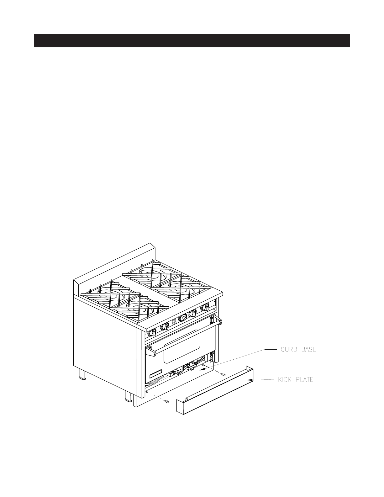
CURB BASE INSTALLATION
The curb base must be installed after the range has
been leveled and set properly in its final location.
To install the curb base, simply remove the kick plate
(the panel immediately below the oven door) and locate the mounting holes at the front of the range base.
Secure the curb base to the front of the range base
using the two hexagonal sheet metals screws provided
with the curb base. If the legs are adjusted to the
minimum height of 4 inches, the curb base can have
0 to 1/8 gap between the floor. When the legs are
adjusted higher, the gap can be as high as 2 inches
which may not be visually objectionable and not need
a filler. If a filler is desired, build a filler attached to the
floor or to the adjacent cabinets using screws or other
removable fasteners, so that the range can be readily
removed if necessary.
5
 Loading...