

Jade JTRH Installation Manual
appliance.
WARNING
RETAIN THIS MANUAL FOR FUTURE REFERENCE
Jade Range
LLC, A Middleby Company
2650 Orbiter Ave.
Brea, CA 92821
Telephone (714) 961-2400
FAX (714) 961-2550
TITAN HEAVY DUTY RANGES
TITAN BAKING AND ROASTING OVENS
MODELS: JTRH and JTRHE Series
INSTALLATION, OPERATION AND MAINTENANCE INSTRUCTIONS
NOTE: Instructions must be posted in a prominent location, which will instruct the user in the event that
he/she detects the smell of gas. This information shall be obtained from your local gas company.
Adequate clearances must be provided in front, rear and at sides of appliance for servicing. The
appliance area must be kept free and clear from combustibles. There must be no material or obstacles
obstruction the flow of combustion and ventilation air.
Improper installation, adjustment, alteration, service or
maintenance can cause property damage, injury or death.
Read the installation, operating and maintenance instructions
thoroughly before installing or serving this equipment.
WHAT TO DO IF YOU SMELL GAS
• Open windows
• Do not touch electric switches
• Extinguish any open flame
• Immediately call your gas company
FOR YOUR SAFETY
Do not store or use gasoline or
other flammable vapors or liquids
in the vicinity of this or any other
P/N 24-132 REV A 7/00 Page 1
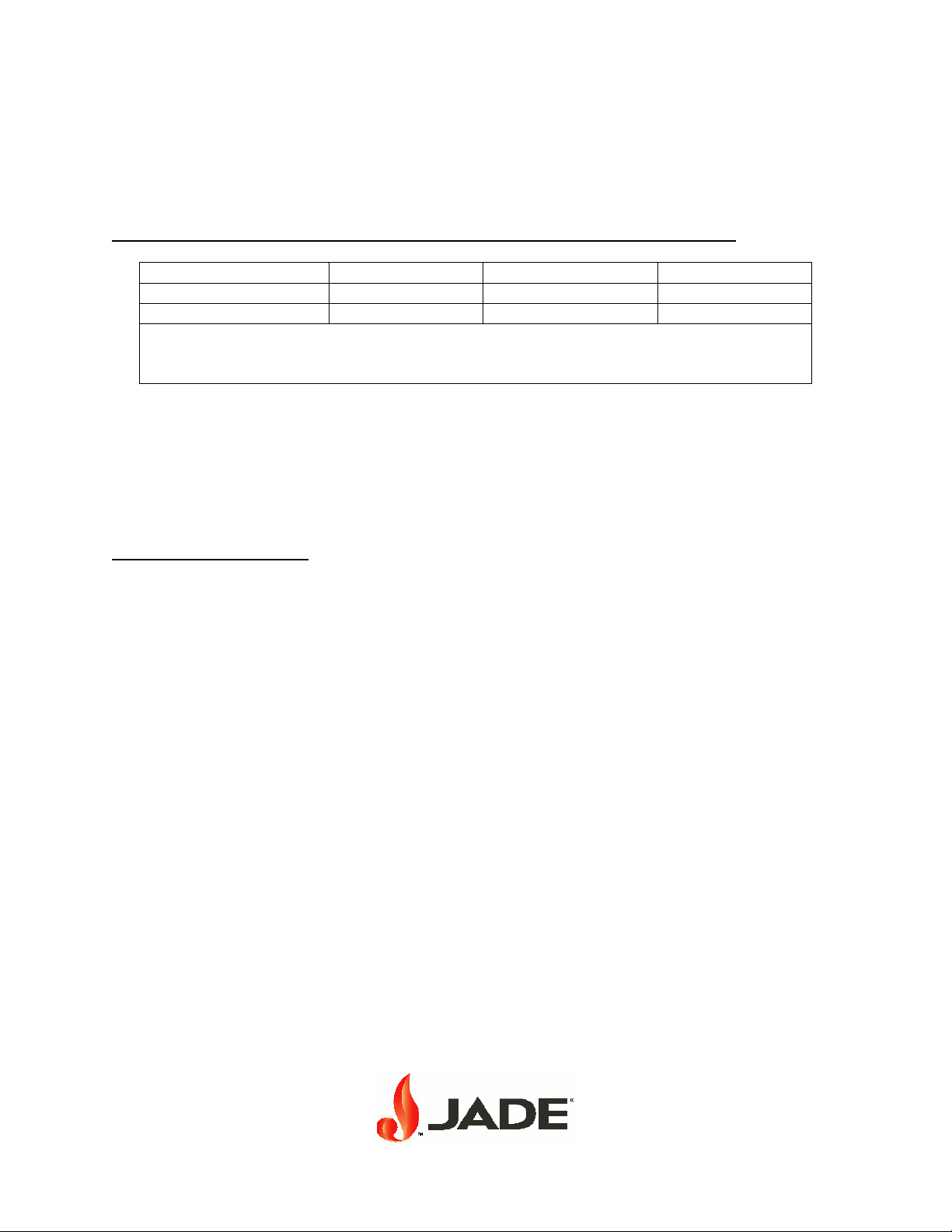
CLEARANCES and VENTILATION
This appliance is design-certified for installation with the following conditions:
MINIMUM CONSTRUCTION CLEARANCES FROM COMBUSTIBLE MATERIALS:
Side Rear Floor
With 6” High Legs 4 inches 2 inches 6 inches
Without 6” High Legs 4 inches 2 inches 0 inch
Without 6” High Legs – Range must be installed on a noncombustible kerb or platform
with the front of the range projection 3-inch minimum over the kerb or platform. Range
may be installed flush against noncombustible rear wall.
NOTE: APPLIANCE INTENDED FOR OTHER THAN HOUSEHOLD USE.
The area in front of and above the appliance must be clear to avoid any obstruction of flow of
combustion and ventilation air. Means must be provided for adequate air supply and adequate
clearance for air openings into the combustion chamber. Keep appliance area free and clear
from combustibles.
IMPORTANT REMINDER: It is the responsibility of the installing contractor to provide a
regulator of sufficient capacity to accommodate the total BTUs required for all the appliances
within the battery that have connecting manifolds. The regulators are to be set at 5” W.C. for
natural gas regulators and 10” W.C. for propane gas regulators.
Insert: Drawing of Model JTRH, JTRHE Series
P/N 24-132 REV A 7/00 Page 2

PREPARATION FOR INSTALLATION
Safe and satisfactory operation of your equipment depends to a great extent upon its proper
installation. Installation must conform with local codes, or in the absence of local, with the
National fuel code, ANSI Z233.1-1988 or later. Electrical installation must conform with all
applicable state and local codes and be in compliance with the National Electrical Code,
ANSI/NFPA 70-1990.
NOTE: AFTER ELECTRICAL INSTALLATION TO THE CONVECTION OVEN MASTER
SWITCH (TOGGLE SWITCH) SHOULD BE TURNED OFF UNTIL OVEN POLOT IS IGNITED
AND APPLIANCE READY FOR USE.
Refer to rating plate for gas-orifice type. If orifices are converted in the field, the rating plate
must be corrected by an experienced and responsible service person. Gas regulator must be
changed to suit gas to be used. Check with appliance manufacturer.
INSTALLATION AND GAS PIPING
♦ Appliances battery-mounted (minimum of two appliances) must be lined up, leveled, and
have manifolds leveled and connected. Plate shelves are adjustable and holes are provided
to take 3/8-16T.P.I. bolts for securely locking plate shelves together. Similar provisions are
provided when appliances are equipped with high shelves.
♦ Adjusting legs that are provided can adequately level floor-mounted appliances. Kerb or
platform-mounted appliances (legs removed) have adjustable leveling bolts located within
the body (Front and rear on bottom of control box area, and within combustion area bottom
on right side of inner body. Remove oven bottom.)
♦ Connect appliances to gas supply line. Under no circumstances should the gas supply line
be smaller than the inlet pipe on the appliance. Use pipe compound on all pipe joints.
Compound must be resistant to the action of liquefied petroleum gases.
♦ Check all gas connections for leaks using soap and water solution. DO NOT USE AN
OPEN FLAME FOR CHECKING PURPOSES.
♦ The appliance and its individual shutoff valve must be disconnected from the gas supply
piping system during any pressure testing of that system at test pressures in excess of ½
psig (3.45 kPa).
♦ The appliance must be isolated from the gas supply piping system by closing its individual
manual shutoff valve during any pressure testing of the gas supply piping system at test
pressures equal to or less than ½ psig (3.5 kPa).
♦ Licensed or approved experienced personnel should do all installation and service work.
P/N 24-132 REV A 7/00 Page 3

LIGHTING AND RELIGHTING INSTRUCTIONS
TOP SECTION:
The top sections of your appliance are equipped with constant burning lighters. Lighters and
burners should be manually lighted immediately after the gas is turned on. Adjustments can be
make through the observation openings in front valve cover. Using a screwdriver, lighter flames
can be adjusted by turning the lighter adjustment screw* clockwise or counterclockwise. Pilots
should be checked periodically to insure pilot ignition.
OVEN SECTION: STANDARD OVEN GAS CONTROLS
1. Turn oven ON-OFF valve to “ON.”
2. Turn thermostat dial to “OFF.” Wait 5 minutes.
3. Remove oven kick plate.
4. Push red button of safety pilot valve and light pilot. Continue to push red button until pilot
flame remains on (minimum of 30 seconds). Release button.
5. Turn thermostat dial to desired temperature.
6. CHECK IF PILOT IS EXTINGUISHED. IF EXTINGUISHED, REPEAT STEPS 1 THRU 4
ABOVE.
7. Replace oven kick plate.
8. Turn thermostat dial to “OFF” to shut down oven.
OVEN SECTION-CONVECTION OVEN-GAS CONTROLS
NOTE: THIS CONVECTION OVEN IS EQUIPPED WITH A SIMPLE TROUBLE-FREE
RELIGHT FEATURE. THIS FEATURE RUNS ON A 120V SYSTEM AND IS IN ADDITION TO
THE STANDARD GAS VALVE SAFETY FEATURE.
TO LIGHT CONVECTION OVEN
With gas turned “ON” to appliance and all top section (range) pilots ignited, turn appliance
master switch to “ON” position – ‘light’ between switches (toggle types) will glow, indicating
power to re-igniter is “ON.”
1. Turn thermostat dial “OFF.” Wait 5 minutes.
2. Remove oven kick plate.
3. Push red button of safety pilot valve and light pilot. Continue to push red button of safety
valve until pilot flame remains on (minimum of 30 seconds). Release button.
4. Turn thermostat dial to desired temperature.
5. When satisfied oven pilot is holding, turn thermostat to desired temperature.
6. Turn off thermostat.
P/N 24-132 REV A 7/00 Page 4
 Loading...