

Jade JMRH Service Manual
Service
Manual
REVIEW COPY 7
Manual number 3000012221
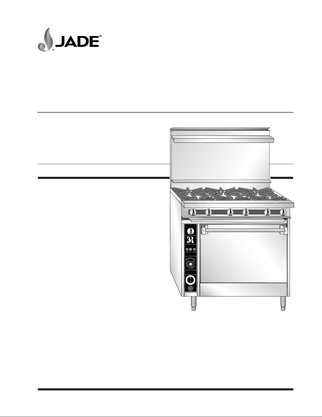
TITAN™
SERIES
SUPER HEAVY DUTY
RANGE LINE
MODEL SERIES JTRH, JMRH & JTRHE
POWERONBLOWER
P.O.
LITEOFF
WARNING
WHEN MAIN GAS TO THE
APPLIANCE IS OFF, POWER
ON SWITCH MUST BE OFF.
THERMOSTAT
0
5
5
500
0
5
4
G
N
I
K
A
B
400
350
WARNING
TURN OFF ELECTRIC & GAS
TO APPLICNCE BEFORE
SERVICING ALL CONTROLS
U
T
E
N
I
M
60
55
50
45
40
25
35
30
AUTO
O
F
F
MANUAL
1
5
0
200
L
O
2
R
5
O
A
0
S
T
300
S
0
5
10
15
20
RETAIN THIS MANUAL FOR FUTURE REFERENCE.
Jade Range LLC
A MIDDLEBY COMPANY 2650 Orbiter Street, Brea, CA 92821 • 714-961-2400 • 800-884-5233 • www.jaderange.com
NOTES:
IN LINE WITH ITS POLICY TO CONTINUALLY IMPROVE ITS PRODUCTS, JADE RANGE, INC. RESERVES THE RIGHT TO CHANGE MATERIALS AND SPECIFICATIONS WITHOUT NOTICE.
JADE RANGE EQUIPMENT IS BUILT TO COMPLY WITH APPLICABLE STANDARDS FOR MANUFACTURERS. INCLUDED AMONG THOSE APPROVAL AGENCIES ARE UL, A.G.A., CSA, ETL AND OTHERS.
TitanTM Series Heavy Duty Range
Model Series JTRH, JMRH & JTRHE
IMPORTANT FOR YOUR SAFETY
THIS MANUAL HAS BEEN PREPARED FOR PERSONNEL QUALIFIED TO INSTALL
ELECTRICAL AND GAS EQUIPMENT, WHO SHOULD PERFORM THE INITIAL FIELD STARTUP
AND ADJUSTMENTS OF THE EQUIPMENT COVERED BY THIS MANUAL.
READ THIS MANUAL THOROUGHLY BEFORE OPERATING, INSTALLING OR PERFORMING
MAINTENANCE ON THE EQUIPMENT.
POST IN A PROMINENT LOCATION THE INSTRUCTIONS TO BE FOLLOWED IN THE EVENT
THE SMELL OF GAS IS DETECTED. THIS INFORMATION CAN BE OBTAINED FROM THE
LOCAL GAS SUPPLIER.
WARNING
Failure to follow instructions in this manual can cause property damage, injury or death.
WARNING
Improper installation, adjustment, alteration, service or maintenance can cause property damage,
injury or death.
Gas connections should be performed only by a certified professional.
Gas connections must comply with the applicable portions of the National Gas Code and/or all local
gas codes. Failure to comply with this procedure can cause property damage, injury or death.
Before connecting the equipment to the gas supply, verify that the gas connections agree with the
specifications on the data plate. Failure to comply can cause property damage, injury or death.
Before performing any service that involves electrical connection or disconnection and/or exposure
to electrical components, always perform the Electrical LOCKOUT/TAGOUT Procedure. Disconnect
all circuits. Failure to comply with this procedure can cause property damage, injury or death.
Before connecting the gas supply line, it must be purged to remove any contaminates. Failure to
comply can cause property damage.
REVIEW COPY 7
WARNING
WARNING
WARNING
WARNING
WARNING
All gas joints disturbed during service must be checked for leaks. Do not use an open flame. Use a
hazardous gas tester or a soap and water solution. Bubbles indicate a gas leak. Failure to comply
can cause property damage, injury or death.
SM-2
Jade Range LLC – A Middleby Company
TM
Titan
Series Heavy Duty Range
Model Series JTRH, JMRH & JTRHE
WARNING
Do not use an open flame to test for a gas leak. Use a hazardous gas tester or a soap and water
solution. Bubbles indicate a gas leak. Failure to comply can cause property damage, injury or death.
WARNING
If a gas leak is detected, do not operate this or any other equipment until the leak has been properly
repaired and residual gas has dissipated. Failure to comply can cause property damage, injury or death.
WARNING
If a gas odor is detected, shut down the equipment at main shutoff valve and contact the local gas
company or gas supplier for service. Failure to comply can cause property damage, injury or death.
WARNING
Before performing any service that involves gas connection or disconnection and/or exposure to
gas, always follow the Gas LOCKOUT/TAGOUT Procedure. Failure to comply can cause property
damage, injury or death.
WARNING
Do not operate this equipment without properly placing and securing all covers and access panels.
Electrical and grounding connections must comply with the applicable portions of the National
Electric Code and/or all local electric codes.
Equipment equipped with a flexible electric supply cord are provided with a three-prong grounding
plug. It is imperative that this plug be connected into a properly grounded three-prong receptacle.
If the receptacle is not the proper grounding type, contact an electrician. Do not remove the
grounding prong from the plug.
REVIEW COPY 7
WARNING
WARNING
WARNING
IMPORTANT
IN THE EVENT A GAS ODOR IS DETECTED, SHUT DOWN UNITS AT MAIN SHUTOFF VALVE
AND CONTACT THE LOCAL GAS COMPANY OR GAS SUPPLIER FOR SERVICE.
DO NOT STORE OR USE GASOLINE OR OTHER FLAMMABLE VAPORS OR LIQUIDS
IN THE VICINITY OF THIS OR ANY OTHER APPLIANCE.
IN THE EVENT OF A POWER FAILURE,
DO NOT ATTEMPT TO OPERATE THIS DEVICE.
Jade Range LLC – A Middleby Company
FOR YOUR SAFETY
SM-3

TM
Series Heavy Duty Range
Titan
Model Series JTRH, JMRH & JTRHE
TABLE OF CONTENTS
GENERAL ...................................................................................................................................................... 6
INSTALLATION ...................................................................................................................................... 6
OPERATION........................................................................................................................................... 6
CLEANING.............................................................................................................................................. 6
TOOLS .................................................................................................................................................... 6
Standard ........................................................................................................................................... 6
Special .............................................................................................................................................. 6
JTRH GAS / BTU / BURNER SPECIFICATIONS................................................................................ 7
REMOVAL AND REPLACEMENT OF PARTS............................................................................................ 8
COMPONENT LOCATOR, EXTERIOR................................................................................................. 8
COMPONENT LOCATOR, MANIFOLD ................................................................................................ 9
COMPONENT FUNCTION .................................................................................................................... 9
ELECTRICAL LOCKOUT/TAGOUT PROCEDURE........................................................................... 10
GAS LOCKOUT/TAGOUT PROCEDURE.......................................................................................... 10
Gas Leak Test................................................................................................................................10
COVERS AND PANELS....................................................................................................................... 11
Manifold Cover, Top Section......................................................................................................... 11
Convection Oven Control Panel.................................................................................................... 11
Ove n D oo r ...................................................................................................................................... 11
Oven Kick Panel............................................................................................................................. 12
COMP ON EN T R EM OV AL.................................................................................................................... 12
Top Section Open Burner and Orifices ........................................................................................ 12
Top Section Valves: Burner, Oven Shut-off, and Pilot ................................................................ 13
Pilot Valves: Top Section Burners .............................................................................................. 13
Burner Valves: Top Section Burners ........................................................................................... 13
Oven Shut-Off Valves .................................................................................................................... 14
Fan Motor Switches and Indicator Light ....................................................................................... 14
Oven Door Switch .......................................................................................................................... 15
Thermostat and Thermocouple..................................................................................................... 16
Oven Pilot Control Valve with Dropout of 20 - 30+ Seconds........................................................ 16
Ignition Module............................................................................................................................... 17
Oven Pilot Assembly /Thermocouple ............................................................................................ 18
Oven Burner Gas Orifice ............................................................................................................... 18
Oven Burner Assembly.................................................................................................................. 19
Oven Timer..................................................................................................................................... 19
Motor and Blower Assembly.......................................................................................................... 20
REVIEW COPY 7
SM-4
Jade Range LLC – A Middleby Company

TM
Titan
Series Heavy Duty Range
Model Series JTRH, JMRH & JTRHE
SERVICE PROCEDURES AND ADJUSTMENTS .................................................................................... 21
GAS SUPPLY PRESSURE CHECK .................................................................................................... 21
GAS PRESSURE REGULATOR VALVE ADJUSTMENT .................................................................. 22
Check for insufficient gas volume ................................................................................................. 22
TOP BURNER PILOT LIGHT ADJUSTMENT..................................................................................... 22
OVEN PILOT LIGHT ............................................................................................................................ 23
AIR SHUTTER ADJUSTMENT ............................................................................................................ 23
If the flame is soft, lazy, or yellow: ................................................................................................ 23
If the flame is lifting off the burner: ............................................................................................... 23
TOP BURNER ADJUSTMENT ............................................................................................................ 24
OVEN BURNER ADJUSTMENT .......................................................................................................... 24
OVEN THERMOSTAT ADJUSTMENT ................................................................................................ 25
Oven Thermostat Test and Calibration ........................................................................................ 25
GRIDDLE THERMOSTAT TEST AND CALIBRATION ...................................................................... 26
IGNITION MODULE CIRCUIT CHECK ............................................................................................... 27
PILOT IGNITER INSPECTION AND ADJUSTMENT ......................................................................... 28
DOOR SWITCH TEST ......................................................................................................................... 29
CONVECTION OVEN MOTOR TEST ................................................................................................. 29
Motor Not Working ......................................................................................................................... 29
Motor Works – Noisy or Does Not Sound Right .......................................................................... 30
BURNER INSPECTION AND REPAIR ................................................................................................ 30
Nozzle and Orifice Check .............................................................................................................. 30
REVIEW COPY 7
TROUBLESHOOTING ................................................................................................................................31
SEQUENCE OF OPERATION – CONVENTIONAL OVEN ................................................................ 31
SEQUENCE OF OPERATION – CONVECTION OVEN .................................................................... 31
CONVECTION OVEN WIRING DIAGRAM ......................................................................................... 32
TROUBLESHOOTING CHART ............................................................................................................ 33
COMMERCIAL EQUIPMENT LIMITED WARRANTY ............................................................................... 39
Jade Range LLC – A Middleby Company
SM-5
GENERAL
TitanTM Series Heavy Duty Range
Model Series JTRH, JMRH & JTRHE
Jade Titan ranges are produced with the finest
workmanship and materials. Proper installation,
usage and maintenance will result in many years
of reliable service.
Before performing maintenance on the range,
thoroughly read this manual and carefully follow
the instructions in the order given.
This manual is applicable to the Jade Titan ranges
listed on the cover page. Procedures in this manual
apply to all models unless specified otherwise.
Pictures and illustrations apply to all models unless
specified otherwise.
REVIEW COPY 7
INSTALLATION
Refer to the Installation and Operation manual.
OPERATION
Refer to the Installation and Operation manual.
CLEANING
Refer to the Installation and Operation manual.
TOOLS
Standard
Standard set of hand tools
VOM with A.C. current tester (Any quality VOM
with sensitivity of 20,000 Ohms/Volt)
Special
Automotive Drum Brake Spring Installation Tool
(For Spring Replacement and Oven Door
Removal)
Temperature Tester (Thermocouple type)
Gas leak detection equipment
Gas pressure manometer
SM-6
Jade Range LLC – A Middleby Company
TM
Titan
Series Heavy Duty Range
Model Series JTRH, JMRH & JTRHE
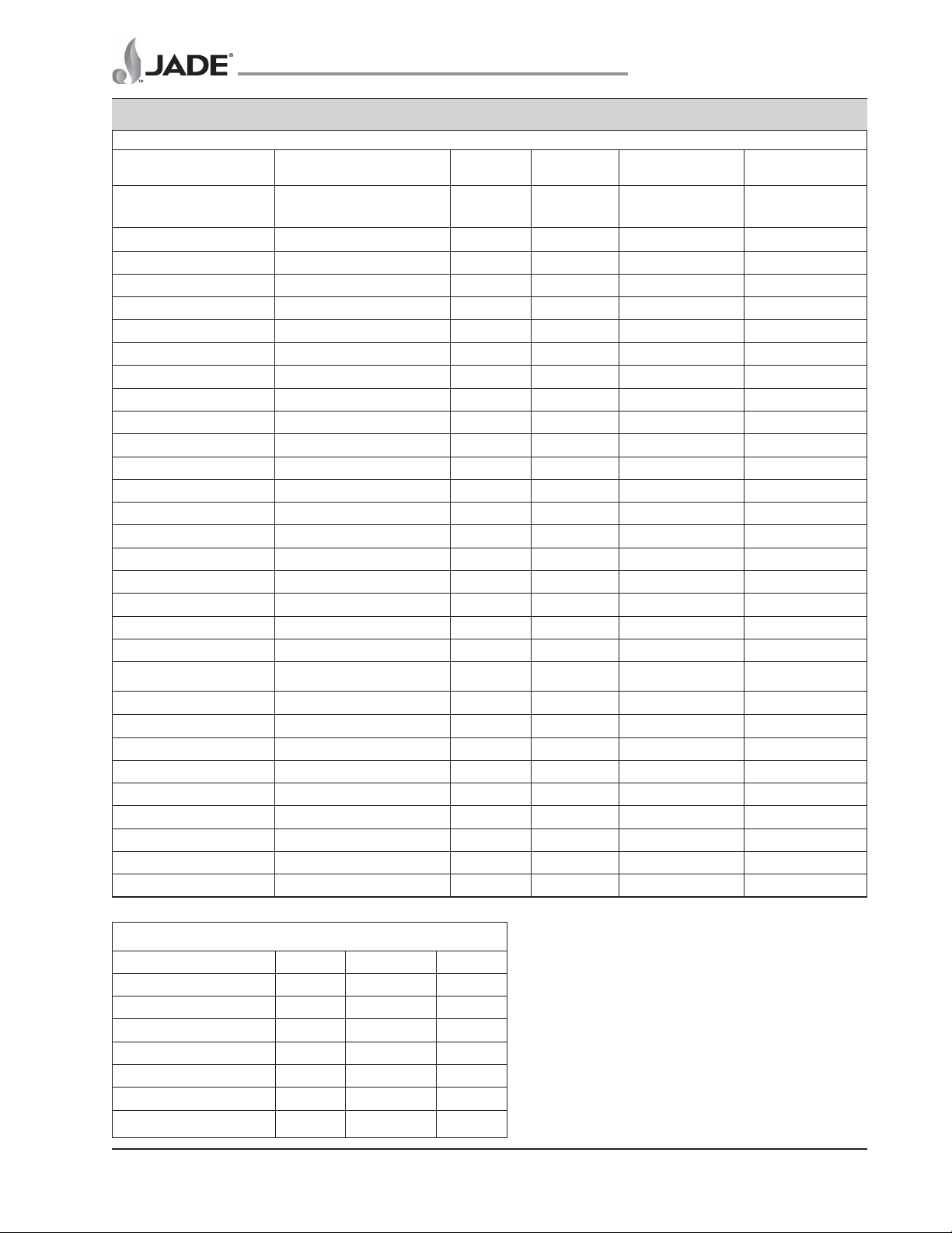
JTRH GAS / BTU / BURNER SPECIFICATIONS
FEA TURE Burner Type Burner BTU’s Natural Propane
Orifice Part Orifice Part
Size No. Size No.
.C.W "01 @.C.W "5 @.oN traP
Current
Open Burner front 2-Piece lift off Hex Head 3000010836 35K 39 4620800000 50 4611900000
Open Burner rear 2-Piece lift off Hex Head 3000010835 35K 39 4620800000 50 4611900000
Fire-N-Ice Saute’ Burners Hex Head bolt-on 920 burner 8492300000 20K 46 4622200000 55 4621100000
Step-Up Burner (4 across) Hex Head bolt-on 915 burner 8406200000 15K 51 4624500000 57 4624600000
Step-Up Burner (3 across) 2-Piece lift off Hex Head 3000010836 30K 39 4620800000 50 4611900000
**Open Burners with “S” grates 2-Piece lift off Hex Head n/a 27K 43 4620700000 53 4621700000
Hot Top Tubular U-burner 1317510090 35K 41 4622900000 52 4621400000
Half Hot Top (rear only) 2-Piece lift off Hex Head 3000010836 15K 51 4624500000 57 4624600000
Griddle (manual control) Tubular U-burner 2500010209 30K 39 4620800000 52 4621400000
Griddle (t-stat control) Tubular U-burner 2500010209 25K 43 4620700000 53 4621700000
French Graduated Hot Top 2-Piece lift off Hex Head 3000010836 30K 41 4622900000 52 4621400000
Plancha 2-Piece lift off Hex Head 3000010836 15K 46 4622200000 56 4621200000
Plancha Tubular U-burner 2500045000 20K 46 4622200000 55 4621100000
Char-Broiler Straight tubular burner 1210600000 15K 51 4624500000 57 4624600000
Robata/Satay Infra-Red burner 1212200000 37K 34 3000012091 49 4626800000
Oven (standard) Tubular U-burner 2500010209 35K 37 4624300000 50 4611900000
Oven (convection) Tubular U-burner 2500010209 30K 41 4622900000 52 4621400000
Pilot for standard oven Pilot only (nat) 4616600100 n/a #18 4617900000 #10 4623700000
Pilot for convection oven Pilot w/electrode (nat) 4619600000 n/a #18 4617900000 #10 4623700000
REVIEW COPY 7
Non-current
Pre ’01
Open Burner front Hex head bolt-on 920 burner 8492300000 20K 44 4621500000 55 4621100000
Open Burner rear Hex head bolt-on 920 burner 8492500000 20K 44 4621500000 55 4621100000
’01-’05
Open Burner front Lift off (donut) style 2500128430 35K 37 4624300000 50 4611900000
Open Burner rear Lift off (donut) style 2500128431 35K 37 4624300000 50 4611900000
Pre ’09
French Graduated Hot Top Round (mfg) burner 1322200090 30K 39 4620800000 52 4621400000
Regulators
Specification Model Part No. Capacity
3/4 x 3/4 nat gas RV-48LT 4613500000 250K
3/4 x 3/4 propane RV-48LT 4613400000 250K
1 x 1 nat gas RV-61 4613700000 750K
1 x 1 propane RV-61 4615800000 750K
1 1/4 x 1 1/4 nat gas RV-61 4613200000 1.1M
1 1/4 x 1 1/4 propane RV-61 4614000000 1.1M
1 1/4 x 1 1/4 **hi-capacity nat **RV-81 4629400000 2.5M
Jade Range LLC – A Middleby Company
SM-7
TM
Series Heavy Duty Range
Titan
Model Series JTRH, JMRH & JTRHE
REMOVAL AND REPLACEMENT OF PARTS
COMPONENT LOCATOR, EXTERIOR
POWERONBLOWER
P.O.
AUTO
O
F
F
LITEOFF
MANUAL
WARNING
WHEN MAIN GAS TO THE
APPLIANCE IS OFF, POWER
ON SWITCH MUST BE OFF.
THERMOSTAT
150
550
200
L
500
O
25
R
0
O
A
0
S
45
T
G
N
30
I
K
A
REVIEW COPY 7
B
400
WARNING
TURN OFF ELECTRIC & GAS
TO APPLICNCE BEFORE
SERVICING ALL CONTROLS
N
I
M
60
55
50
45
40
35
0
0
35
U
T
E
S
0
5
10
15
20
25
30
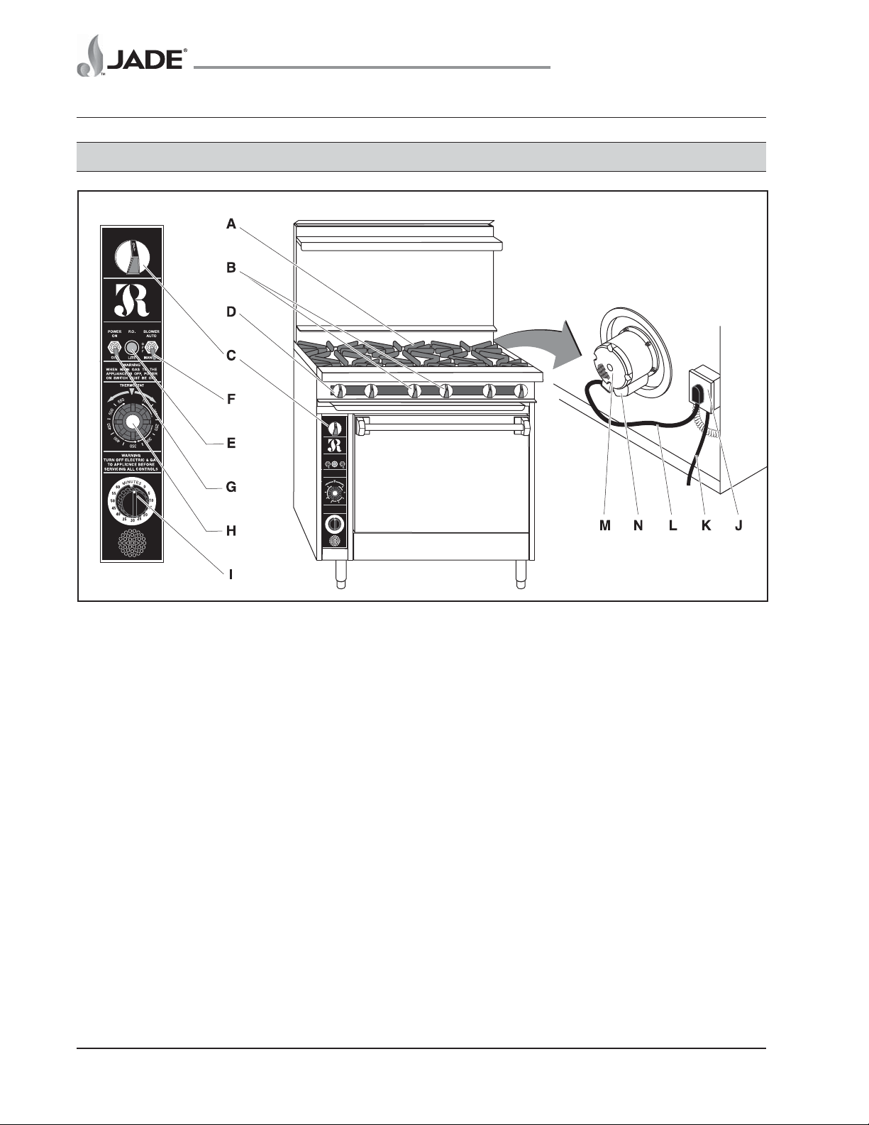
Figure 1: Component Locator, Exterior
A. Burner Grates
B. Burner Control Valves
C. Oven Gas Shut-Off Valve
D. Alternate Oven Shut-Off Valve Location
(Some models)
E. Power ON (P.O.) Light
F. Blower AUTO/MANUAL Switch
G. Power ON/OFF Switch
H. Thermostat Knob
I. Ove n Timer (Optional)
J. Electrical Junction Box
K. Power Cord
L. Fan Power Cord
M. Convection Fan Motor
N. Capacitor Cover (Capacitor located under
cover)
SM-8
Jade Range LLC – A Middleby Company
TM
Titan
Series Heavy Duty Range
Model Series JTRH, JMRH & JTRHE
COMPONENT LOCATOR,
MANIFOLD
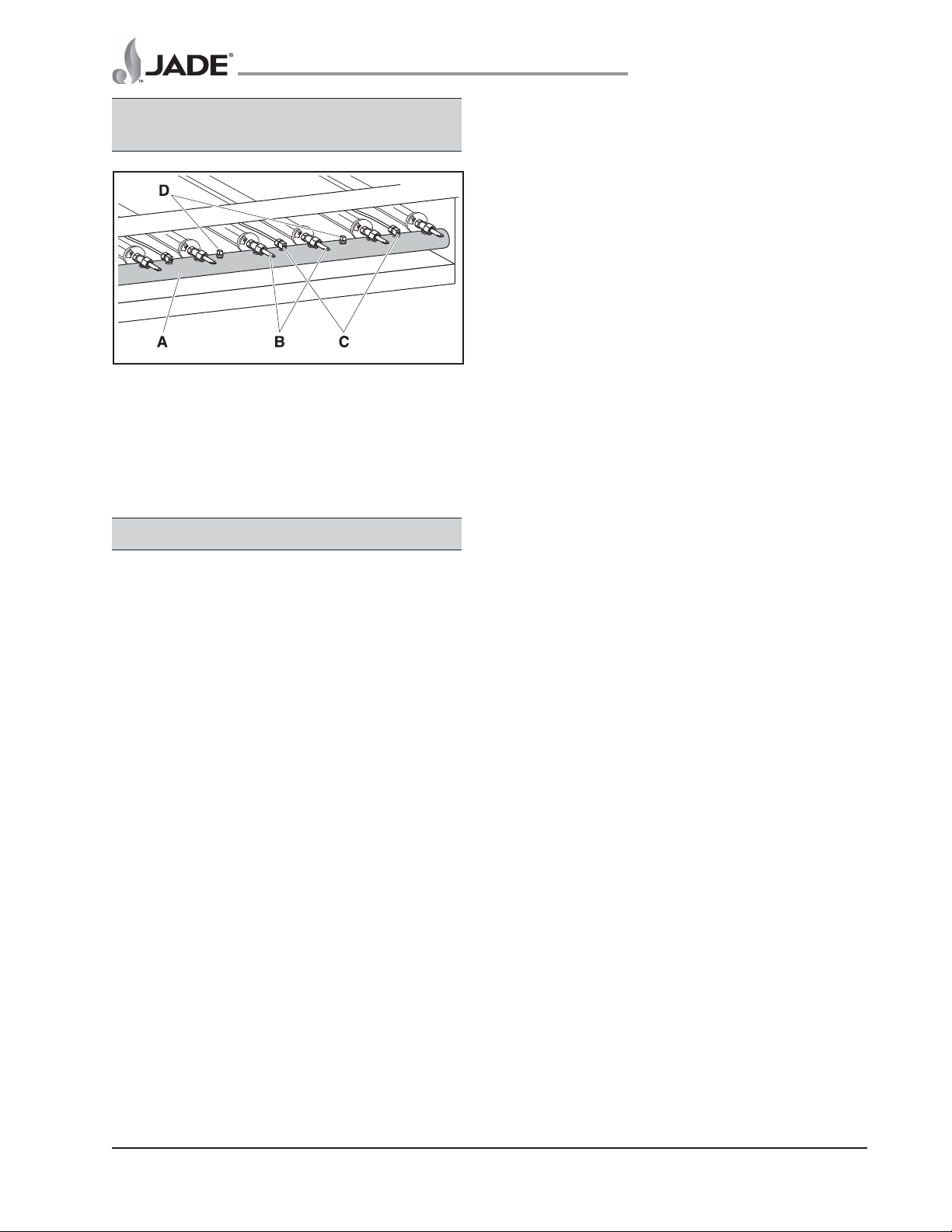
Figure 2: Component Locator, Manifold
A. Manifold
B. Burner Controls (w/Orifices)
C. Pilot Adjustment Valves
D. Pressure Test Plugs
COMPONENT FUNCTION
Control Valves, Top Burners
Brass control valves are used by the operator to
turn on/adjust the gas supply to the burners.
Control Valve, Oven Gas Supply Shut-off
The oven gas shut-off valve turns the gas to the
oven on or off.
Oven Door Switch (Convection models only)
The door switch is located under the oven control panel.
When the oven door opens, the switch opens the circuit
shutting off the fan motor. If door plunger switch has
failed, the AUTO/MANUAL switch will not shut off the fan.
Ignition Module (Convection models only)
The ignition module controls and supplies high
voltage to the oven pilot igniter.
Manifold
The gas supply manifold is located behind the top
section burner knobs. The burner control valves
are attached to the manifold, which is a large pipe
full of gas under pressure.
Motor, Convection Oven
The single-phase convection oven motor circulates
oven heated air. The motor electrical circuit is routed
REVIEW COPY 7
through door switch and through the blower AUTO/
MANUAL switch. The door closes the door switch and
allows voltage to flow from the door switch to the motor.
The motor should operate with the door open when the
blower switch is in the manual position.
Orifice
Each burner is supplied with gas through an
orifice.
Pressure Regulator
The pressure regulator regulates the incoming supply
pressure to keep the pressure of gas in the range at
a constant level (5" WC nat., 10" WC propane).
Oven Pilot and Control Valve Assembly
The safety control valve senses the presence of
the pilot light via the thermocouple and opens the
gas valve to the oven only when the pilot light is lit.
Thermocouple/Safety Control Valve
The thermocouple on the pilot safety valve
prevents gas from being sent to the oven burners
unless the pilot light is on.
Pilot Valve Assembly, Top Burners
Adjustable valves in the gas manifold control
the flow of gas to the individual pilot lights for
the top burners.
Oven Thermostat
The thermostat regulates oven temperature by
regulating the gas flow to the oven as required to
maintain oven temperature.
Oven Timer (Optional)
The oven timer control provides an audible alert
after a specific time interval.
Junction Box (Convection models only)
The junction box is located at the rear of the range
and is the connection point for electrical wires that
control the convection fan motor.
Power Cord (Convection models only)
The power cord connects the range to the power
source. The convection oven will not operate
unless connected to an electrical power supply.
Conventional ovens and top burners do not require
electrical power to operate.
Jade Range LLC – A Middleby Company
SM-9
TitanTM Series Heavy Duty Range
Model Series JTRH, JMRH & JTRHE
ELECTRICAL LOCKOUT/
TAGOUT PROCEDURE
WARNING
BEFORE PERFORMING ANY SERVICE THAT
INVOLVES ELECTRICAL CONNECTION OR
DISCONNECTION AND/OR EXPOSURE TO
ELECTRICAL COMPONENTS, ALWAYS
PERFORM THE ELECTRICAL LOCKOUT/
TAGOUT PROCEDURE. DISCONNECT ALL
CIRCUITS. FAILURE TO COMPLY CAN CAUSE
PROPERTY DAMAGE, INJURY OR DEATH.
The Electrical LOCKOUT/TAGOUT Procedure is
used to protect personnel working on an electrical
equipment. Before performing any maintenance
or service that requires exposure to electrical
components, follow these steps:
1. In electrical box, place equipment circuit
breaker into OFF position.
2. Place a lock or other equipment on electrical
box cover to prevent someone from placing
circuit breaker ON.
REVIEW COPY 7
The Gas LOCKOUT/TAGOUT Procedure is used to
protect personnel working on a gas equipment.
Before performing any maintenance or service that
requires gas disconnections, follow these steps:
1. Locate the gas shutoff valve or inlet.
2. Place the valve in the OFF position.
3. Place a tag on the valve indicating that service
is being performed on equipment and the gas
must remain off until service is complete.
4. Place a locking device on the gas valve or
inlet, preventing connection until the lock is
removed.
5. On the equipment, make sure all flame sources
are extinguished and/or removed.
6. Bleed residual gas from the equipment inlet
line and allow time for the gas to dissipate
before beginning service on the equipment.
Gas Leak Test
WARNING
3. Place a tag on electrical box cover to indicate
that equipment has been disconnected for
service and power should not be restored until
tag is removed by maintenance personnel.
4. Disconnect equipment power cord from
electrical outlet.
5. Place a tag on the cord to indicate that
equipment has been disconnected for service
and power should not be restored until tag is
removed by maintenance personnel.
GAS LOCKOUT/TAGOUT
PROCEDURE
WARNING
BEFORE PERFORMING ANY SERVICE
THAT INVOLVES GAS CONNECTION OR
DISCONNECTION AND/OR EXPOSURE TO
GAS, ALWAYS FOLLOW THE GAS LOCKOUT/
TAGOUT PROCEDURE. FAILURE TO COMPLY
CAN CAUSE PROPERTY DAMAGE, INJURY
OR DEATH.
ALL GAS JOINTS DISTURBED DURING
SERVICE MUST BE CHECKED FOR LEAKS.
DO NOT USE AN OPEN FLAME. USE A
HAZARDOUS GAS TESTER OR A SOAP AND
WATER SOLUTION. BUBBLES INDICATE A
GAS LEAK. FAILURE TO COMPLY CAN CAUSE
PROPERTY DAMAGE, INJURY OR DEATH.
WARNING
IF A GAS LEAK IS DETECTED, DO NOT
OPERATE THIS OR ANY OTHER EQUIPMENT
UNTIL THE LEAK HAS BEEN PROPERLY
REPAIRED. FAILURE TO COMPLY CAN CAUSE
PROPERTY DAMAGE, INJURY OR DEATH.
After completing service on any gas equipment,
all gas joints disturbed during service must be
checked for leaks. DO NOT USE AN OPEN
FLAME. Use a hazardous gas tester or use a soap
and water solution as follows:
1. Apply a soap and water solution to gas joint
and check for bubbles.
2. If bubbles are present, the joint is leaking and
must be repaired before using the equipment.
SM-10
Jade Range LLC – A Middleby Company
TM
Titan
Series Heavy Duty Range
Model Series JTRH, JMRH & JTRHE
COVERS AND PANELS
Manifold Cover, Top Section
Figure 3: Manifold Cover, Top Section
A. Gas Valve Knobs
B. Cover Screws
C. Manifold Cover
1. Loosen set screw and remove all knobs
from control valves.
2. Remove four (4) manifold cover screws.
3. Remove manifold cover.
REVIEW COPY 7
WARNING
PERFORM THE ELECTRICAL LOCKOUT/
TAGOUT PROCEDURE.
1. Shut off all electric controls and perform the
Electrical LOCK/TAGOUT procedure.
2. Remove thermostat and gas ON/OFF knobs.
3. Remove cover retaining screw.
4. Pull panel out to clear thermostat shaft.
5. Reverse the procedure to install the panel.
Oven Door
4. Reverse the procedure to install the cover.
Convection Oven Control Panel
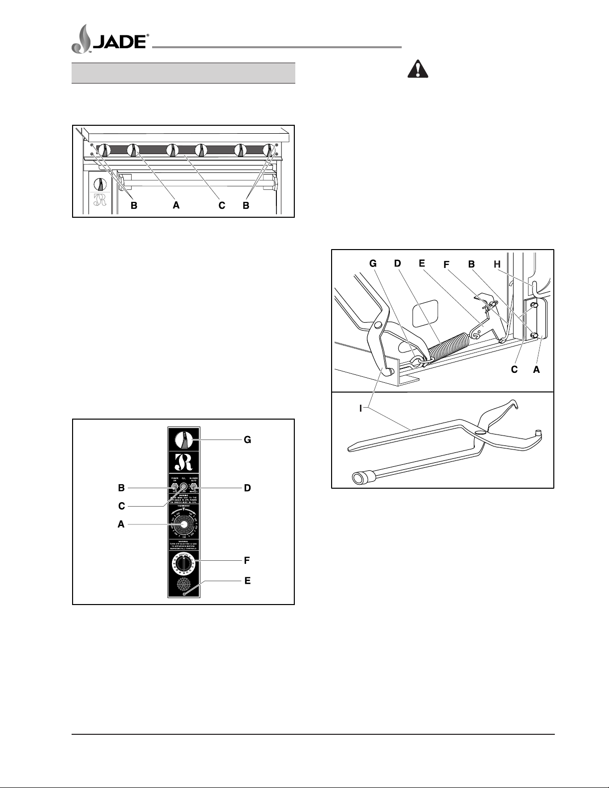
Figure 4: Convection Oven Control Panel
A. TEMPERATURE Control Knob
B. Power ON/OFF Switch
C. Power ON Indicator Light
D. Blower AUTO/OFF/MANUAL Switch
E. Retaining Screw
F. Timer
G. Gas ON/OFF Valve for Oven
Figure 5: Oven Door Operating Mechanism
A. Oven Door Hinge
B. Hinge Bolts
C. Door Hinge Shims
D. Door Spring
E. Rocker Arm
F. “S” Hook
G. Eyelet
H. J-Hook to Mount Kick Panel
I. Brake Spring Tool
1. Remove kick plate as described under
COVERS AND PANELS.
Jade Range LLC – A Middleby Company
SM-11

TitanTM Series Heavy Duty Range
Model Series JTRH, JMRH & JTRHE
WARNING
RISK OF BODILY INJURY! OVEN SPRING IS
UNDER CONSIDERABLE TENSION. EXERCISE
GREAT CARE IN REMOVING OR REPLACING
SPRING.
2. Using an automotive brake spring pliers release
spring from eyelet as shown in Figure 5.
3. Remove wire S-Hook to rocker arm from oven
door hinge.
4. Loosen the four bolts that attach oven door hinges.
5. Remove door hinges from behind the door.
6. Using an assistant to support door, remove
four hinge bolts that attach hinges to frame.
7. Reverse the procedure to install the door.
Oven Kick Panel
REVIEW COPY 7
COMPONENT REMOVAL
Top Section Open Burner and Orifices
Figure 7: Top Section Open Burner
and Orifices
A. Manifold
B. Top Burners
C. Burner Control Valve with Orifice
D. Pilot Valve
Figure 6: Oven Kick Panel
A. Oven Kick Panel
B. J-Hook (on Hinge)
1. Lift oven kick panel straight up to release tabs
from retaining slots and pull out to remove.
2. To install the oven kick panel, insert tabs into
hinge J-Hook slots and slide panel towards
bottom of range.
WARNING
PERFORM THE ELECTRICAL LOCKOUT/
TAGOUT PROCEDURE.
1. Shut off all electrical controls and perform the
Electrical LOCKOUT/TAGOUT procedure.
WARNING
PERFORM THE GAS LOCKOUT/TAGOUT
PROCEDURE.
2. Shut off all gas controls and perform the Gas
LOCKOUT/TAGOUT procedure.
3. Remove top grates to expose burners.
4. Remove manifold cover as per COVERS AND
PANELS.
NOTE: It is not necessary to remove pilot tubes in
order to remove burner assemblies.
5. Lift burner assembly at rear of range and
pull away from burner control/orifice to
remove.
SM-12
6. Reverse the procedure to install the burner
assembly.
Jade Range LLC – A Middleby Company
 Loading...