

Jade JMRH Installation Manual
InstallaInstalla
Installa
InstallaInstalla
tion &tion &
tion &
tion &tion &
TITAN™
SERIES
SUPER HEAVY DUTY
RANGE LINE
MODEL SERIES JTRH, JMRH & JTRHE
OperOper
Oper
OperOper
ManualManual
Manual
ManualManual
aa
tiontion
a
tion
aa
tiontion
POWERONBLOWER
P.O.
AUTO
O
F
F
LITEOFF
MANUAL
WARNING
WHEN MAIN GAS TO THE
APPLIANCE IS OFF, POWER
ON SWITCH MUST BE OFF.
THERMOSTAT
150
550
200
L
500
O
250
R
O
A
S
450
T
G
N
300
I
K
A
B
400
350
WARNING
WHEN MAIN GAS TO THE
APPLIANCE IS OFF, POWER
ON SWITCH MUST BE OFF.
TURN OFF ELECTRIC & GAS
TO APPLIANCE BEFORE
SERVICING ALL CONTROLS.
Please read this manual completely before attempting to
install or operate this equipment! Notify carrier of damage.
Inspect all components immediately.
RETAIN THIS MANUAL FOR FUTURE REFERENCE.
Jade Range LLC
A MIDDLEBY COMPANY 2650 Orbiter Street, Brea, CA 92821 • 714-961-2400 • 800-884-5233 • www.jaderange.com
NOTES:
IN LINE WITH ITS POLICY TO CONTINUALLY IMPROVE ITS PRODUCTS, JADE RANGE, LLC RESERVES THE RIGHT TO CHANGE MATERIALS AND SPECIFICATIONS WITHOUT NOTICE.
JADE RANGE EQUIPMENT IS BUILT TO COMPLY WITH APPLICABLE STANDARDS FOR MANUFACTURERS. INCLUDED AMONG THOSE APPROVAL AGENCIES ARE UL, A.G.A., CSA, ETL AND OTHERS.
Manual number 2413200000 revC Printed in U.S.A.
TitanTM Series Heavy Duty Range
Model Series JTRH & JTRHE
IMPORTANT FOR YOUR SAFETY
THE INSTALLATION INSTRUCTIONS CONTAINED HEREIN ARE FOR THE USE OF QUALIFIED
INSTALLATION AND SERVICE PERSONNEL ONLY. INSTALLATION OR SERVICE BY OTHER THAN
QUALIFIED PERSONNEL MAY RESULT IN DAMAGE TO THE UNIT AND/OR INJURY TO THE OPERATOR.
Qualified installation personnel are individuals, a firm, corporation, or company which either in person or through
a representative are engaged in and are responsible for:
A. The installation or replacement of gas piping or the connection, installation, repair or servicing of equipment, who
is experienced in such work familiar with all precautions required, and have complied with all requirement of state
or local authorities having jurisdiction. Reference: National Fuel Gas Code, ANSI Z223.1, section 1.4, latest
addendum, or National Gas - Propane Installation Code CSA B149.1 as applicable.
B. The installation of electrical wiring from the electric meter, main control box or service outlet to the
electric appliance. Qualified installation personnel must be experienced in such work, be familiar with
all precautions required and have complied with all requirements of state and local authorities having
jurisdiction. Reference: National Electric Code, ANSI/NFPA No. 70, latest addendum.
JADE TITAN SERIES RANGE(S) MUST BE INSTALLED IN ACCORDANCE WITH LOCAL CODES, OR
IN THE ABSENCE OF LOCAL CODES, WITH THE NATIONAL FUEL GAS CODE, ANSI Z223.1 LATEST
ADDENDUM, INCLUDING:
The appliance and its individual shutoff valve must be disconnected from the gas supply piping system
during any pressure testing of that system at test pressures in excess of 1/2 psig (14" WC/3.45 kPa).
The appliance must be isolated from the gas supply piping system by closing its individual manual shutoff
valve during any pressure testing of the gas supply piping system at test pressures equal to or greater than
1/2 psig (14" WC/3.45 kPa).
POST IN A PROMINENT LOCATION THE INSTRUCTIONS TO BE FOLLOWED IN
THE EVENT THE SMELL OF GAS IS DETECTED. THIS INFORMATION CAN BE
OBTAINED FROM THE LOCAL GAS SUPPLIER.
W ARNING
IN THE EVENT OF A POWER FAILURE, DO NOT ATTEMPT TO OPERATE THIS DEVICE.
IMPORTANT
IN THE EVENT A GAS ODOR IS DETECTED, SHUT DOWN UNITS AT MAIN SHUTOFF VALVE
AND CONTACT THE LOCAL GAS COMPANY OR GAS SUPPLIER FOR SERVICE.
FOR YOUR SAFETY
DO NOT STORE OR USE GASOLINE OR OTHER FLAMMABLE VAPORS OR LIQUIDS
IN THE VICINITY OF THIS OR ANY OTHER APPLIANCE.
W ARNING
IMPROPER INSTALLATION, ADJUSTMENT, ALTERATION, SERVICE OR MAINTENANCE
CAN CAUSE PROPERTY DAMAGE, INJURY OR DEATH. READ THE INSTALLATION,
OPERATING AND MAINTENANCE INSTRUCTIONS THOROUGHLY BEFORE INSTALLING,
SERVICING OR OPERATING THIS EQUIPMENT.
IO-2
Jade Range LLC – A Middleby Company

TM
Titan
Series Heavy Duty Range
Model Series JTRH & JTRHE
Contents
INTRODUCTION ...............................................................................................................................................................4
UNPACKING / INITIAL INSPECTION ...................................................................................................................... 4
GENERAL ...................................................................................................................................................................4
DATA PLATE LOCATION .......................................................................................................................................... 4
LOCATION..................................................................................................................................................................4
GAS CONNECTIONS ................................................................................................................................................4
GENERAL RANGE SPECIFICATIONS .................................................................................................................... 5
TITAN OVEN Specifications ...................................................................................................................................... 5
GAS BURNER BTU SPECIFICATIONS ................................................................................................................... 5
INSTALLATION .................................................................................................................................................................6
HOOD AND VENTILATION REQUIREMENTS ........................................................................................................ 6
Combustion Air....................................................................................................................................................6
Ventilation ............................................................................................................................................................6
BATTERY INSTALLATION REQUIREMENTS ........................................................................................................ 6
Waldorf Configuration.........................................................................................................................................6
ADJUSTABLE LEG INSTALLATION ........................................................................................................................ 7
OPTIONAL CASTER INSTALLATION......................................................................................................................7
RESTRAINING DEVICE INSTALLATION ................................................................................................................ 7
HI-SHELF /RISER INSTALLATION .......................................................................................................................... 8
MOUNTING SALAMANDER OR CHEESEMELTER ............................................................................................... 8
INSTALLATION CODES AND STANDARDS ..........................................................................................................8
ELECTRICAL INSTALLATION (CONVECTION MODELS ONLY).........................................................................8
Clearances from Combustible Materials ...........................................................................................................8
LEVELING...................................................................................................................................................................9
GAS LINE AND REGULATOR INSTALLATION ...................................................................................................... 9
Gas Line Pressure Testing.................................................................................................................................9
Gas Leak Check................................................................................................................................................10
BURNER FLAME ADJUSTMENTS.........................................................................................................................10
Flame Characteristics for a Properly Adjusted Burner .................................................................................. 10
Top Burner Pilot Adjustment ............................................................................................................................10
Top Burner Adjustment ..................................................................................................................................... 11
Oven, Griddle and Hot Top Burner Adjustment (Tubular Type Burners) .....................................................11
OPERATION ....................................................................................................................................................................12
TOP BURNER CONTROLS ....................................................................................................................................12
LIGHTING OVEN PILOT LIGHT ............................................................................................................................. 13
Standard Oven ..................................................................................................................................................13
Convection Oven...............................................................................................................................................13
Convection Oven Re-Igniter (Electronic Ignition)........................................................................................... 14
CONVECTION OVEN OPERATION.......................................................................................................................14
Convection Oven Controls ...............................................................................................................................14
Lowering/Changing Oven Temperature ..........................................................................................................15
Use of Oven Without Blower Fan ....................................................................................................................15
STANDARD OVEN OPERATION ........................................................................................................................... 16
CARE AND CLEANING ..................................................................................................................................................17
SERVICE..........................................................................................................................................................................18
LIMITED WARRANTY.....................................................................................................................................................19
CA PROP 65 GAS WARNING........................................................................................................................................20
Jade Range LLC – A Middleby Company
IO-3
INTRODUCTION
TitanTM Series Heavy Duty Range
Model Series JTRH & JTRHE
UNPACKING / INITIAL INSPECTION
This appliance was inspected before leaving the
factory. After unpacking, inspect the unit for any
damage that may have occurred during shipping.
**The transportation company assumes all
responsibility for safe delivery. If the appliance is
found to be damaged, save all packaging materials
and contact the carrier within 7 days of delivery.
Move the appliance as close as possible to
installation location. Remove all boxes and
packaging material from inside of oven. Remove
all shipping banding from pallet and top of range.
Remove all tops and oven components from their
boxes.
GENERAL
Jade Titan ranges are manufactured for use with
natural or propane gas. The gas type for each
range and the BTU rate is listed on the name
plate. Verify the unit is for the correct gas type
before installing it, by reading specifications on
appliance rating plate. Please read the installation
instructions carefully. Proper installation is
essential for safe and trouble free operation of this
appliance.
LOCATION
Locate appliance in an area that will make it easy
to load and unload the oven and will facilitate the
movement of food orders. Read Ventilation
Requirements in the Installation portion of this
manual before locating the appliance.
WARNING
THE EQUIPMENT AREA MUST BE KEPT FREE
AND CLEAR OF ANY COMBUSTIBLE
MATERIALS.
GAS CONNECTIONS
Titan ranges are supplied with a 1-1/4" front manifold
and a 1" rear tailpipe. For rear connection, remove
cap. Ranges are supplied with 3/4" gas pressure
regulator. Operating pressure is 5.0" W.C. for natural
gas or 10.0" W.C. for propane gas.
**Maximum incoming pressure is 14.0" W.C.(1/2 psi
3.45 kPa)
NOTE: Gas Pressure Regulator must be installed
in an accessible “cool zone” protected from grease
and debris.
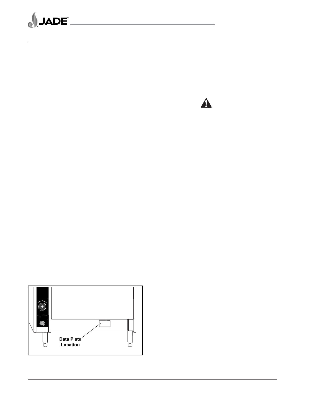
DATA PLATE LOCATION
Remove the kick plate. The data plate is located
to the right of center (behind the kick plate) beneath
the oven door. If gas orifices or regulator types
(gas or propane) are changed in the field, the
rating plate must be changed to reflect the new
orifice or gas type. All work should be performed
by a licensed and qualified professional.
WARNING
WHEN MAIN GAS TO THE
APPLIANCE IS OFF, POWER
ON SWITCH MUST BE OFF.
THERMOSTAT
150
550
200
L
500
O
250
R
O
A
S
450
T
G
N
300
I
K
A
B
400
350
WARNING
WHEN MAIN GAS TO THE
APPLIANCE IS OFF, POWER
ON SWITCH MUST BE OFF.
TURN OFF ELECTRIC & GAS
TO APPLIANCE BEFORE
SERVICING ALL CONTROLS.
Figure 1: Data Plate
NOTE: Use a pipe joint compound that has been
approved for use with liquefied petroleum gases.
IO-4
Jade Range LLC – A Middleby Company
36"
(914)
2 1/2"
REAR GAS CONNECTION
(64)
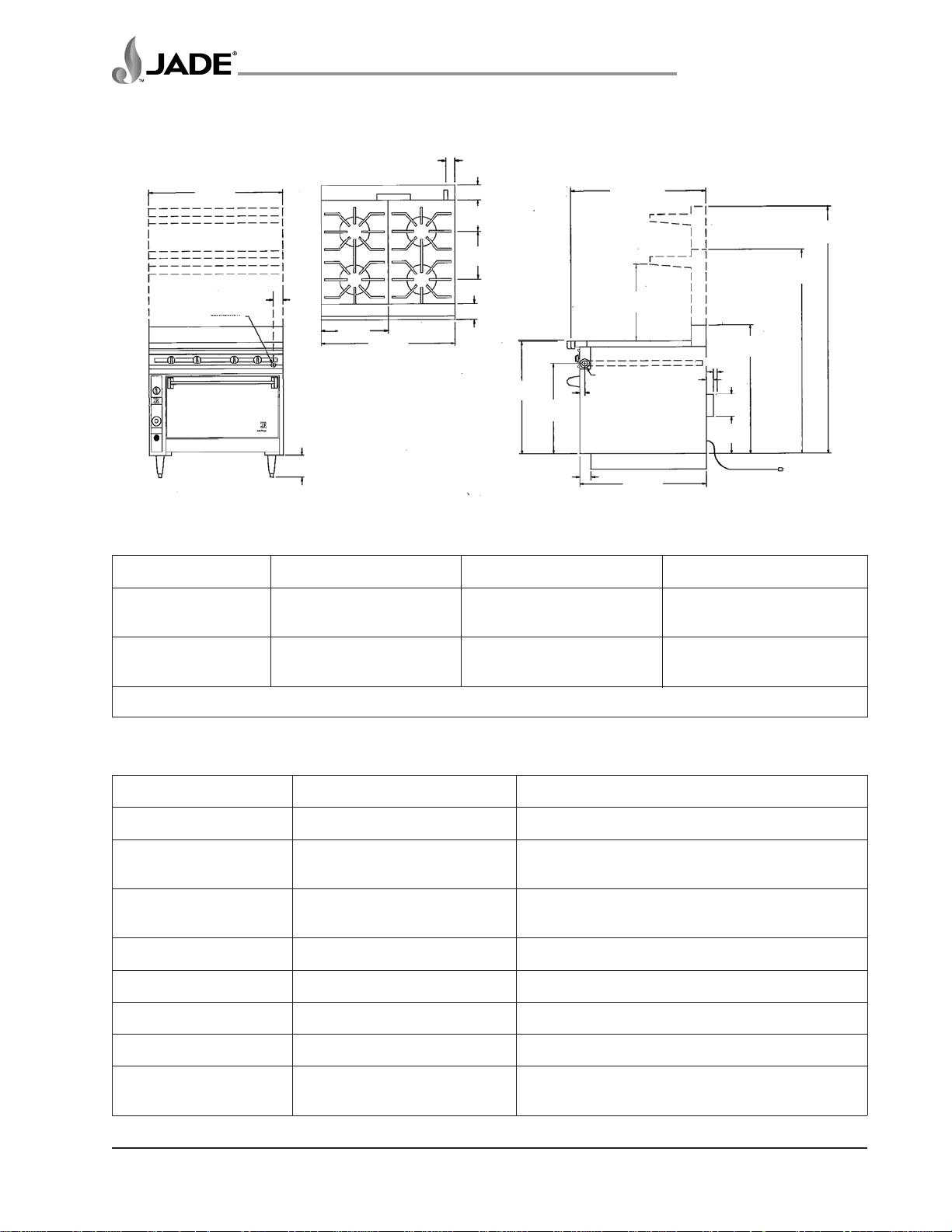
GENERAL RANGE SPECIFICATIONS
2 1/2"
36"
(914)
(64)
4" (102)
8 1/2"
(216)
13"
(330)
4 1/4" (108)
30 1/2"
(775)
24 3/8"
(619)
(76)
3"
6"
(152)
REAR GAS CONNECTION
18"
(457)
( ) = MILLIMETERS
Titan
36 1/4"
(921)
20 1/2"
(521)
REAR GAS CONNECTION
1 1/4" MANIFOLD
(32)
1 1/2"
(38)
BLOWER MOTOR FOR
CONVECTION OVEN ONLY
CURB
34" (864)
TM
Series Heavy Duty Range
Model Series JTRH & JTRHE
DOUBLE DECK SHELF
SINGLE DECK SHELF
STUB
34 3/4"
BACK
(883)
CLEARANCE
1"
2"
(25)
(51)
6"
(1525)
10"
(254)
115V, 60c. Elect. Supply Cord (9 ft long)
Convection Oven Only
55"
(1397)
66 1/2"
(1689)
TITAN OVEN SPECIFICATIONS
Model Width Height Depth
Standard Oven 28-1/4″ 14″ 27-3/4″
(71.75 cm) (35.56 cm) (70.48 cm)
Convection Oven 28″ 13-3/4″ 24-1/2″
(71.12 cm) (34.92 cm) (62.23 cm)
Convection ovens are provided with 1/4 HP, 115 Volt, 60HZ, 1-Phase Blower Motor
GAS BURNER BTU SPECIFICATIONS
MODEL/FEATURE BTU NOTES
Open Burners 35,000 BTU per burner Lift-off octagon type
Manual Griddle 30,000 BTU per burner
Thermo Griddle 25,000 BTU per burner 1 every 12" of griddle width
Hot Top 35,000 BTU per burner 12" or 18" width full front to rear
Half Hot Top 17,500 BTU per burner Rear only
Robata/Satay 35,000 BTU per burner 2 IR burners per grid section
French Top Range 30,000 BTU per burner 1 for each top section
Char Broilers 15,000 BTU per burner 1 every 6" of broiler width
Plancha 20,000 BTU per burner 18"/24" – 1 burner / 36" – 2 burners
Standard Oven 35,000 BTU per burner
Convection Oven 30,000 BTU per burner
Jade Range LLC – A Middleby Company
Thermostat adjustable from 150°F to 550°F
IO-5
INSTALLATION
TitanTM Series Heavy Duty Range
Model Series JTRH & JTRHE
HOOD AND VENTILATION
REQUIREMENTS
Combustion Air
This appliance should be installed in an environment
capable of providing adequate combustion air for
the range. Titan ranges and the BTU consumption
for each feature are listed under GAS BURNER
BTU SPECIFICATIONS chart at the beginning of
this manual. Locate the particular model/features
being installed and note its BTU output of the features
of each appliance, then add the BTU rate for all
burners operating at once. IT IS IMPORTANT THAT
ADEQUATE COMBUSTION AIR BE PROVIDED
FOR THE TOTAL BTU CALCULATED. Avoid
locating the appliance in a tightly confined area that
is incapable of providing sufficient combustion air.
Clear space MUST be provided in front of the
appliance to allow for entry of combustion air.
Ventilation
An exhaust hood with code-approved fire controls
and sufficient CFM exhaust must be provided to
remove excess heat/steam/grease, etc. from
cooking. The hood canopy must extend beyond all
sides of the appliance. Refer to Standard NFPA No.
96 (latest edition) for the removal of smoke and
grease laden vapors from commercial cooking
equipment. Use the BTU listings under GAS
BURNER BTU SPECIFICATIONS chart at the
beginning of this manual to calculate the total BTU,
and then furnish exhaust air CFM required. Room
ventilation (make-up air) must be provided to
compensate for air being removed by exhaust
system. Excessive negative room air pressure will
result if this is not done. Lack of exhaust and/or
excessive negative pressure will interfere with oven
and pilot light operation and result in pilot outage,
improper combustion, and poor overall performance.
can be connected via plumbing unions. Failure to
level all appliances to the same plane will prevent
the proper interconnection of gas manifolds. If the
manifolds do not line up from one appliance to
another, re-check the level and correct so that
appliances are leveled to the same plane.
Install the first appliance in the position it will
occupy in the battery. Align and level the second
appliance to it and connect gas manifolds together.
Continue until all appliances are installed.
CAUTION
Provisions for gas and electrical shut offs must be
incorporated in the design of the “battery” and
accessible in the event the appliance is to be serviced.
CAUTION
All gas manifolds must align correctly to each
other. Failure to provide proper alignment can
damage gas manifolds, pilots and gas valves.
Adequate air supply must be provided for
combustion air. Provide a minimum of 36" of free
space in front of all appliances. Provide adequate
clearance for all air openings into combustion
chamber on all appliances.
Provide a gas regulator sufficient to supply adequate
gas flow for the total BTU requirement of all
appliances that have connecting manifolds. Set gas
regulators for 5.0" W.C. for natural gas regulators
and 10.0" W.C. for propane gas regulators.
Plate shelves and high shelves can be locked
together with standard 3/8" bolts.
When installed and individually connected to the
gas supply, each appliance must have its own
shutoff valve for servicing of the appliance.
BATTERY INSTALLATION
REQUIREMENTS
Ranges that are installed in a battery (two or
more) must be aligned, leveled, with manifolds
leveled and connected to each other.
Care must be exercised in leveling all appliances to
the same plane. This is important so that the 1-1/4"
gas manifolds located at the front of each appliance
IO-6
Waldorf Configuration
In Waldorf configuration, appliances are grouped
together to form an appliance island. Care must be
exercised in leveling all appliances to the same plane.
Establishing a level line around the entire perimeter of
the island will assist in installing all appliances. This is
important so that the 1-1/4" gas manifolds located at
the front of each appliance can be connected via
plumbing unions. Failure to level all ranges to the same
plane will prevent the proper interconnection of gas
Jade Range LLC – A Middleby Company
 Loading...