

Jade JCO Installation Manual
WARNING
RETAIN THIS MANUAL FOR FUTURE REFERENCE
Jade Range LLC, A Middleby Company
2650 Orbiter Ave.
Brea, CA 92821
Telephone (714) 961-2400
FAX (714) 961-2550
JADE CONVECTION OVEN
INSTALLATION, OPERATION AND MAINTENANCE INSTRUCTIONS
NOTE: Instructions must be posted in a prominent location, which will instruct the user in the
event that he detects the smell of gas. This information shall be obtained from your local gas
company.
Improper installation, adjustment, alteration,
service or maintenance can cause property
damage, injury or death. Read the
installation, operating and maintenance
instructions thoroughly before installing or
serving this equipment.
FOR YOUR SAFETY
Do not store or use gasoline
or other flammable vapors or
liquids in the vicinity of this or
any other appliance.
P/N 24-156 REV A 7/00 Page 1
TABLE OF CONTENTS
OPER
ATION INSTRUCTIONS
MAINTENANCE INSTRUCTIONS
GAS SPECIFICATIONS……………………………………….2
FUTURE OVEN INFORMATION……………………………..3
INSTALLATION INSTRUCTIONS…………………………….3
DELIVERY AND INSPECTION………………………3
LOCATION OF OVEN………………………………...3
MINIMUM CLEARANCE…………………………10,11
ELECTRICAL CONNECTIOS……………………...7,8
VENTILATION………………………………………….9
AIR AND HEAT FLOW…………………………………….…..6
COOK ONLY-OVEN CONTROLS…………………...…….…..13
-OVEN OPERATIONS… ………………..…………14
COOK & HOLD-OVEN CONTROLS………………..……...15
-OVEN OPERATIONS…….…………………..……16
GENERAL GUIDELINES…..…………………….………….19
CLEANING AND PREVENTIVE MAINTENANCE………..19
ADJUSTMENTS………………………………………………17
TENSION OF CHAIN MECHANISM………………17
DOORS SYNCHRONIZATION……..…..…………17
CONERSION NATURAL-PROPANE……………………….12
REGULATOR ADJUSTMENT AND CONVERSION….…..20
REMOVAL AND REPLACEMENT…………...………..……18
ACCESS PANELS …..…………………….…………………18
BLOWER ASSEMBLY……………………………...………..21
MOTOR ASSEMBLY…………………………………………22
CONTROL BOX, SWING PANEL…………………………..23
WIRING DIAGRAM…………………………………………...24
P/N 24-156 REV A 7/00 Page 2
FUTURE OVEN INFORMATION
STOP
STOP
FOR FUTURE REFERENCE
TO OPERATOR, INSTALLER, USER
IT IS NECESSARY TO REGISTER MODEL NUMBER
AND SERIAL NUMBER FOR WARRANTY SERVICE.
WHERE CAN YOU FIND MODEL NUMBER AND SERIAL NUMBER?
MODEL # MODEL # MODEL #
(LOCATION OF NAMEPLATE)
Insert -- DIAGRAM CONVECTION OVEN
STOP
P/N 24-156 REV A 7/00 Page 3
GAS SPECIFICATION
JADE RANGE
NATURAL GAS PROPANE GAS
GAS INLET
PRESSURE (at Manif.)
OVEN INPUT
PER BURNER
PER OVEN
MAIN OFFICE
ORIFICE SIZE
US UNITS SI UNITS US UNITS SI UNITS
5” W.C.
20,000 BTU/hr
80,000 BTU/hr
#47
1.25 kPa
5.9 kW
23.4 kW
10” W.C.
20,000 BTU/hr
80,000 BTU/hr
2.5 kPa
5.9 kW
23.4 kW
#55
Installation must conform with local codes or in the absence of local codes, with the National
Fuel Gas Code, ANSIZ223.1, Natural Gas Installation Code, CAN/CGA-B149/1, or the
Propane Installation Code, CAN/CGA-B149.2, as a applicable, including:
1. The appliance and its individual shutoff valve must be disconnected form the gas supply
piping system during any pressure testing of that system at pressures in excess of ½ psig
(kPa).
2. The appliance must be isolated from the gas supply piping system by closing its individual
manual shutoff valve during any pressure testing of the gas supply piping system at
pressures equal to or less than psig (3.45 kPa)
P/N 24-156 REV A 7/00 Page 4

INSTALLATION INSTRUCTIONS
WARNING
LOCATION OF OVEN
QUALIFIED INSTALLATION
AND SERVICE PERSONNEL
ONLY
DELIVERY AND INSPECTION:
ALL JADE RANGE OVENS ARE CAREFULLY INSPECTED AND PACKED, TO PREVENT
SHIPPING DAMAGE.
UPON DELIVERY OF YOUR JADE RANGE OVEN:
• INSPECT THE SHIPPING CONTAINER FOR EXTERNAL DAMAGE
• UNCRATE OVEN AND CHECK FOR CONCEALED DAMAGE.
IT IS THE CARRIER’S FULL RESPONSIBILITY FOR LOSS OR DAMAGE SUFFERED IN
TRANSIT.
LOCATION OR PLACEMENT OF OVENS MUST BE AS FOLLOWS
• FREE OR DRAFT
• ACCESSIBLE FOR PROPER OPERATION AND SERVICING: ALLOW MINIMUM
OF 3 FEET FROM THE FRONT OF THE APPLIANCE
• FREE AND CLEAR OF COMBUSTIBLE MATERIALS
• MINUMUM OF 6” MUST BE MAINTAINED BETWEEN ANY SURFACE OF THE
OVEN AN A COMBUSTIBLE MATERIAL
NOTE: AN APPROPRIATE EXHAUST HOOD IS REQUIRED TO ENSURE AN ADEQUATE
SUPPLY OF FRESH AIR FOR PROPER VENTILATION.
P/N 24-156 REV A 7/00 Page 5
CONVECTION OVEN
INSERT PICTURE
P/N 24-156 REV A 7/00 Page 6

RADIANT BURNER CONVECTED
HEAT HEAT HEAT
CLEARANCES/INSTALLATION
1. For installation in fire-resistant locations only.
2. For installation with the following minimum clearances to combustible clearances:
Sides = 6 inches
Back = 3 inches
3. For installation with legs or casters directly on floor.
P/N 24-156 REV A 7/00 Page 7
ELECTRICAL CONNECTION
WARNING!
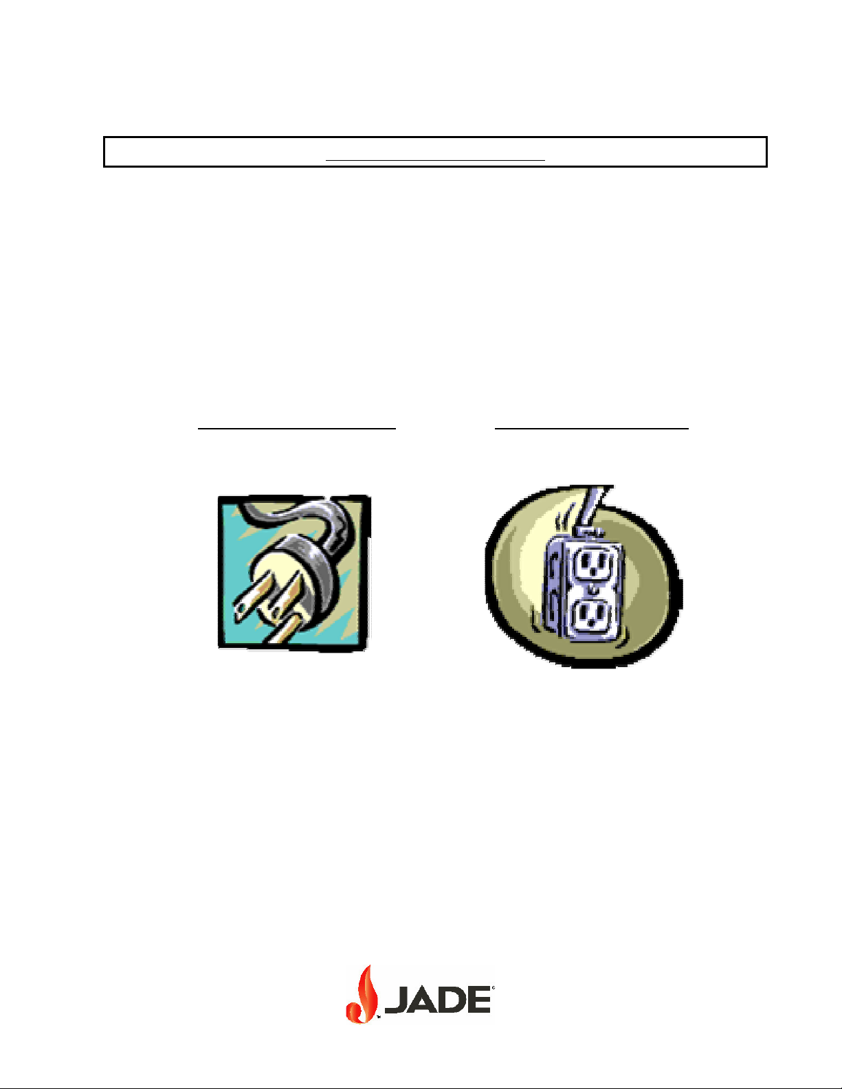
Electrical Grounding Instructions
This appliance is equipped with a three-prong (grounding)
plug for your protection against shock hazard and should be
plugged directly into a properly grounded three-prong receptacle.
Do not cut or remove the grounding prong from this plug.
Picture of power supply cord Picture of 3-prong receptacle
NOTE: A WIRING DIAGRAM IS LOCATED INSIDE THE CONTROL COVER.
This appliance must be electrically grounded in accordance with local codes, or in the
absence of local codes, with the National Electrical Code, ANSI/NFPA 7, or the
Canadian Electrical Code, CSA C22.2, as applicable.
P/N 24-156 REV A 7/00 Page 8

ELECTICAL CONNECTION
For an appliance equipped with casters:
1. The installation shall be made with a connector that complies with the Standard for
connectors for Movable Gas Appliances, ANSIZ21.69 or Connectors for
Moveable Gas Appliances, CAN/CGA-6.16, and a quick-disconnect device that
complies with the Standard for Quick-Disconnect Devices for Use with Gas Fuel,
ANSIZ21.41, OR Quick-Disconnect Devices for Use with Gas Fuel, CAN1-6.9 to
limit the movement of the appliance without depending on the connector and the
Quick-discount device or its associated piping attach a restraining device.
2. The restraining device may be attached to the appliance at the location shown in
Figure.
Insert Picture
P/N 24-156 REV A 7/00 Page 9
 Loading...