

JADAK a business unit of Novanta NOVA001 User Manual
SKYEMODULE NOVA DATASHEET
V1.4

SkyeModule Nova Datasheet - Preliminary Page | 2
Skyetek Inc
1732 Wazee St. Ste 202
Denver, CO 80202
www.skyetek.com
Main 720.328.3425 Fax:720.228.2400
COPYRIGHT INFORMATION:
Copyright 2014 SkyeTek, Inc., 1732 Wazee St. Suite 202, Denver, Colorado 80202, U.S.A. All rights reserved.
Version 031014
This product or document is protected by copyright and distributed under licenses restricting its use, copying, distribution, and decompilation. No part of this
product or docume nt may be reproduced in any form by any means without prior written authorizat ion of SkyeTek and its licensors, if any.
SkyeTek and SkyeWare are trademarks or registered trademarks of SkyeTek, Inc.
MIFARE and NXP is a registered trademark of Royal Philips Electronics.
MicroSoft and Windows are registered trademarks of Microsoft Corporation.
TECHNICAL SUPPORT AN D CONTACT INFORMAT ION
SkyeTek, Inc.
1732 Wazee St. Suite 202
Denver, CO 80202
http://www.skyetek.com
SALES:
sales@skyetek.com
TECHNICAL SU PP ORT:
support@skyetek.com

SkyeModule Nova Datasheet - Preliminary Page | 3
Skyetek Inc
1732 Wazee St. Ste 202
Denver, CO 80202
www.skyetek.com
Main 720.328.3425 Fax:720.228.2400
TABLE OF CONTENTS
1 INTRODUCTION .............................................................................................................................................. 7
1.1 GETTING STARTED .............................................................................................................................................. 7
1.2 WHY A SKYETEK MODULE? .................................................................................................................................. 7
1.3 ADDITIONAL READING ......................................................................................................................................... 8
1.4 REVISION HISTORY .............................................................................................................................................. 8
2 DEFINITION OF TERMS ................................................................................................................................... 8
3 ORDERING INFORMATION ............................................................................................................................. 9
3.1 NOVA STANDARD PART NUMBERS ......................................................................................................................... 9
3.2 HOW TO BUY ..................................................................................................................................................... 9
4 SKYEMODULE NOVA OVERVIEW .................................................................................................................. 10
4.1 D
4.2 BLOCK DIAGRAM .............................................................................................................................................. 10
4.3 FEATURES ........................................................................................................................................................ 11
4.4 APPLICATIONS .................................................................................................................................................. 11
4.5 AGENCY APPROVALS ......................................................................................................................................... 12
5 MECHANICAL SPECIFICATIONS ..................................................................................................................... 12
5.1 CONNECTOR DESCRIPTIONS ................................................................................................................................ 13
5.2 HOST INTERFACE CONNECTOR PIN MAPPING ......................................................................................................... 13
5.3 USING THE GPIO PINS ...................................................................................................................................... 14
6 ELECTRICAL SPECIFICATIONS ........................................................................................................................ 15
6.1 ELECTRICAL CHARACTERISTICS ............................................................................................................................. 15
6.2 ABSOLUTE MAXIMUM RATINGS ........................................................................................................................... 16
7 ENVIRONMENTAL SPECIFICATIONS .............................................................................................................. 16
7.1 ELECTROSTATIC PRECAUTIONS ............................................................................................................................. 16
7.2 GENERAL RATINGS AND OPERATING CONDITIONS ................................................................................................... 16
8 SYSTEM PERFORMANCE ............................................................................................................................... 17
8.1 SYSTEM RANGE ................................................................................................................................................ 17
ESCRIPTION
.................................................................................................................................................. 10
9 REGULATORY APPROVALS AND MODULE INTEGRATION GUIDELINES .......................................................... 17
9.1 AGENCY APPROVALS ......................................................................................................................................... 17
9.2 FCC/IC GUIDELINES (ENGLISH) ........................................................................................................................... 17
9.3 FCC/IC GUIDELINES (FRANÇAIS) ......................................................................................................................... 20
9.4 EU GUIDELINES ................................................................................................................................................ 23
10 HOST INTERFACE SPECIFICATIONS ............................................................................................................ 23
10.1 USB 2.0 ......................................................................................................................................................... 25

SkyeModule Nova Datasheet - Preliminary Page | 4
Skyetek Inc
1732 Wazee St. Ste 202
Denver, CO 80202
www.skyetek.com
Main 720.328.3425 Fax:720.228.2400
10.2 TTL SERIAL ...................................................................................................................................................... 26
10.3 SPI ................................................................................................................................................................ 28
10.4 I2C ................................................................................................................................................................. 31
11 SKYEMODULE NOVA ANTENNA OPTIONS ................................................................................................. 33
12 COMMUNICATING WITH THE MODULE .................................................................................................... 34
12.1 HOST COMMUNICATION (SKYETEK PROTOCOL V3).................................................................................................. 34
12.2 REQUEST FORMATS ........................................................................................................................................... 34
12.3 RESPONSE FORMATS ......................................................................................................................................... 35
13 SYSTEM PARAMETERS .............................................................................................................................. 36
13.1
S
YSTEM PARAMETER SUMMARY
.................................................................................................................. 36
13.2 CHANGING SYSTEM PARAMETERS ........................................................................................................................ 37
13.3 SYSTEM PARAMETER DETAILS.............................................................................................................................. 37
14 SPECIAL FEATURES
.................................................................................................................................. 46
14.1 SLEEP MODES .................................................................................................................................................. 46
14.2 FEATURE REQUESTS .......................................................................................................................................... 46

SkyeModule Nova Datasheet - Preliminary Page | 5
Skyetek Inc
1732 Wazee St. Ste 202
Denver, CO 80202
www.skyetek.com
Main 720.328.3425 Fax:720.228.2400
LIST OF FIGURES
Figure 3-1: SkyeTek Part Number Format ..................................................................................................................... 9
Figure 4-1: SM-GM-AC (with all connectors) ............................................................................................................... 10
Figure 4-2: SkyeModule Nova Block Diagram .............................................................................................................. 11
Figure 5-1: SM-GM Mechanical Drawing ..................................................................................................................... 12
Figure 6-1: Host Interface Connector Pin Numbering ................................................................................................. 14
Figure 9-2: Range Specifications .................................................................................................................................. 17
Figure 11-1: USB Connection Diagram ........................................................................................................................ 25
Figure 11-2: TTL Serial Connection Diagram ................................................................................................................ 26
Figure 11-3: TTL Serial Timing Diagram ....................................................................................................................... 27
Figure 11-4: SPI Connection Diagram .......................................................................................................................... 28
Figure 11-5: SPI Request Setup and Sample Timing .................................................................................................... 29
Figure 11-6: SPI Request Timing .................................................................................................................................. 29
Figure 11-7: SPI Response Timing ................................................................................................................................ 30
Figure 11-8: I2C Connection Diagram........................................................................................................................... 31
Figure 11-9: I2C Timing Diagram .................................................................................................................................. 33

SkyeModule Nova Datasheet - Preliminary Page | 6
Skyetek Inc
1732 Wazee St. Ste 202
Denver, CO 80202
www.skyetek.com
Main 720.328.3425 Fax:720.228.2400
LIST OF TABLES
Table 1-1: Revision History ............................................................................................................................................ 8
Table 3-1: Nova Standard Part Numbers ....................................................................................................................... 9
Table 3-2: Part Number Details ..................................................................................................................................... 9
Table 6-1: SkyeModule Nova Connector Specification ................................................................................................ 13
Table 6-2: SkyeModule Nova Pin Descriptions ............................................................... Error! Bookmark not defined.
Table 7-1: Environmental Ratings/Operating Conditions ............................................................................................ 16
Table 8-1: SkyeModule Nova Electrical Specifications ................................................... Error! Bookmark not defined.
Table 8-2: Absolute Maximum Ratings ........................................................................... Error! Bookmark not defined.
Table 13-1: Request Format (bytes), ASCII Mode ........................................................................................................ 34
Table 13-2: Request Format (bytes), Binary Mode ...................................................................................................... 34
Table 13-3: Response Format (bytes), Binary Mode ................................................................................................... 35
Table 14-1: SkyeModule Nova System Parameters ..................................................................................................... 36
Table 14-10: Common Power Values........................................................................................................................... 41
Table 14-11: Commonly Used Frequencies ................................................................................................................. 43
Table 14-12: Common Modulation Depth Values ....................................................................................................... 44
Table 14-13: Regulatory Mode Values......................................................................................................................... 44

SkyeModule Nova Datasheet - Preliminary Page | 7
Skyetek Inc
1732 Wazee St. Ste 202
Denver, CO 80202
www.skyetek.com
Main 720.328.3425 Fax:720.228.2400
1 Introduction
1.1 Getting Started
Operating your SkyeModule Nova begins with finding a method to connect to a host. The SkyeModule itself does
not operate without direction (commands) from a host. The host can be in the form of a PC or, more typically, an
embedded microcontroller. This document explains the physical and electrical characteristics of the module, so
you can understand how to integrate the Nova into a finished product.
For initial demonstration of the module, SkyeWare v4 software is available on the media that came with the
developer/evaluation kit or available for download at support.skyetek.com. Open this software on your windows
PC and it will be recognized when you connect through USB or RS232 (with developer kit interface board). The
software demonstrates features like selecting tags, reading and writing. It also has a powerful command builder
that lets you format, send and receive any command to and from the reader. More about SkyeWare can be found
in the SkyeWare User Guide. See the Additional Reading section below.
The next step after demonstrating the module’s functionality is developing your own communication with the
module. This can be achieved with simple code on a microcontroller or using the SkyeTek API on a PC. Once
connected to a host through one of the four host interfaces, the reader to host communication is formatted with a
full featured protocol called SkyeTek Protocol v3. In order to make learning commands and formatting easy, we
have developed a series of application notes with examples to get you started. The application notes start with
basic tag and reader commands and become very detailed for tags with special features. Read more about the
protocol and commands in section 12, Communicating with the Module and then move on to the Additional
Reading in section 1.3.
1.2 Why a SkyeTek Module?
Many customers may wonder, “What value does a module add over an RFID transceiver chip?”
RFID transceiver chips may seem simple, but they actually require significant engineering time and capital
investment to integrate. Transceiver chips contain up to 50 registers for configuration and functionality. In
addition, communicating over air protocols such as ISO18000-6C is complex, described in nearly 150 pages of
cryptic procedures. For example, just selecting a tag requires a minimum of 6 and up to 100 over air interactions
with multiple tags present. SkyeTek has also optimized the complex RF chain to give the best performance and
efficiency possible. SkyeTek modules mask the complexities of RFID from the user and pack functionality into
just a few commands.
SkyeTek’s core set of commands allow the user to read and write to tags with a single command, regardless of the
tag type. The module is also field upgradable, so you can use the latest security algorithms and tag features as they
are released. Power regulation and filtering for the radio are handled in the Nova, so you can supply voltage
directly from an unregulated source like a battery. Finally, the Nova will be modularly approved by the FCC and CE,
so you can bypass expensive radio testing at a certified test lab and avoid potential schedule delays due to failures.
Using a SkyeTek module will greatly reduce time to market and upfront development costs. Allow SkyeTek to
take the burden of developing an RF system so you can focus your energy on your core products.

SkyeModule Nova Datasheet - Preliminary Page | 8
Skyetek Inc
1732 Wazee St. Ste 202
Denver, CO 80202
www.skyetek.com
Main 720.328.3425 Fax:720.228.2400
Revision
Author
Change
031014
Josh Peifer
Initial draft.
Rev 1.0
Mark Matlin
Initial Release
Rev 1.1
Mark Matlin
Added Regulatory Section
Rev 1.2
Mark Matlin
Incorporated TCB changes
Rev 1.3
Mark Matlin
Updated recommended antennas for reverse polarity
Rev 1.4
Mark Matlin
Updated MPE distance to 23cm for IC
3DES
Triple Data Encryption Standard
AES
Advanced Encryption Standard
API
Application Programming Interface
DES
Data Encryption Standard
GPIO
General Purpose Input/Output
HID
Human Interface Device
I2C
Inter-integrated Circuit
LSB
Least Significant Bit
MSB
Most Significant Bit
NC
No Connect
RoHS
Reduction of Hazardous Substances
SPI
Serial Peripheral Interface
SSEL
Slave Select
STP V3
SkyeTek Protocol Version 3
TTL
Transistor-transistor Logic
1.3 Additional Reading
SkyeTek Protocol v3 Reader Commands – Application note with descriptions and examples of the reader
commands: read/write system, read/write default system, load defaults, and reset.
1.4 Revision History
Table 1-1: Revision History
2 Def inition of Terms
SkyeModule Nova Datasheet - Preliminary Page | 9
Skyetek Inc
1732 Wazee St. Ste 202
Denver, CO 80202
www.skyetek.com
Main 720.328.3425 Fax:720.228.2400
Part Number
Host Interface
Baud Rate
Description
SM-NV-00
USB (HID)
12Mbps
Mini PCI express connector
PF-PT-BT-OPTS
Product Family
Product Type
Build Type
Options
Code
Options
Description
Product Family
SM = SkyeModule
Highest level product family code.
Product Type
NV = NOVA
Specifies the specific part type.
Build Type
Specifies hardware form factor.
Options
Blank = Standard
This field is left for special customer part numbers or standard
variations such I2C for I2C as the default host interface. Consult the
SkyeTek sales team for custom orders.
3 Ordering Information
3.1 Nova Standard Part Numbers
Table 3-1: Nova Standard Part Numbers
The Nova part number is constructed according to the SkyeTek part number specification below:
Figure 3-1: SkyeTek Part Number Format
Table 3-2: Part Number Details
3.2 How to Buy
SkyeTek products are available through a worldwide distribution network including Digikey, Mouser and Atlas
RFID. Products are also available directly from SkyeTek. For more information on how to purchase SkyeTek
products in your area, please visit the How To Buy page on the SkyeTek website at www.skyetek.com/howtobuy.
SkyeModule Nova Datasheet - Preliminary Page | 10
Skyetek Inc
1732 Wazee St. Ste 202
Denver, CO 80202
www.skyetek.com
Main 720.328.3425 Fax:720.228.2400
4 SkyeModule Nova Overview
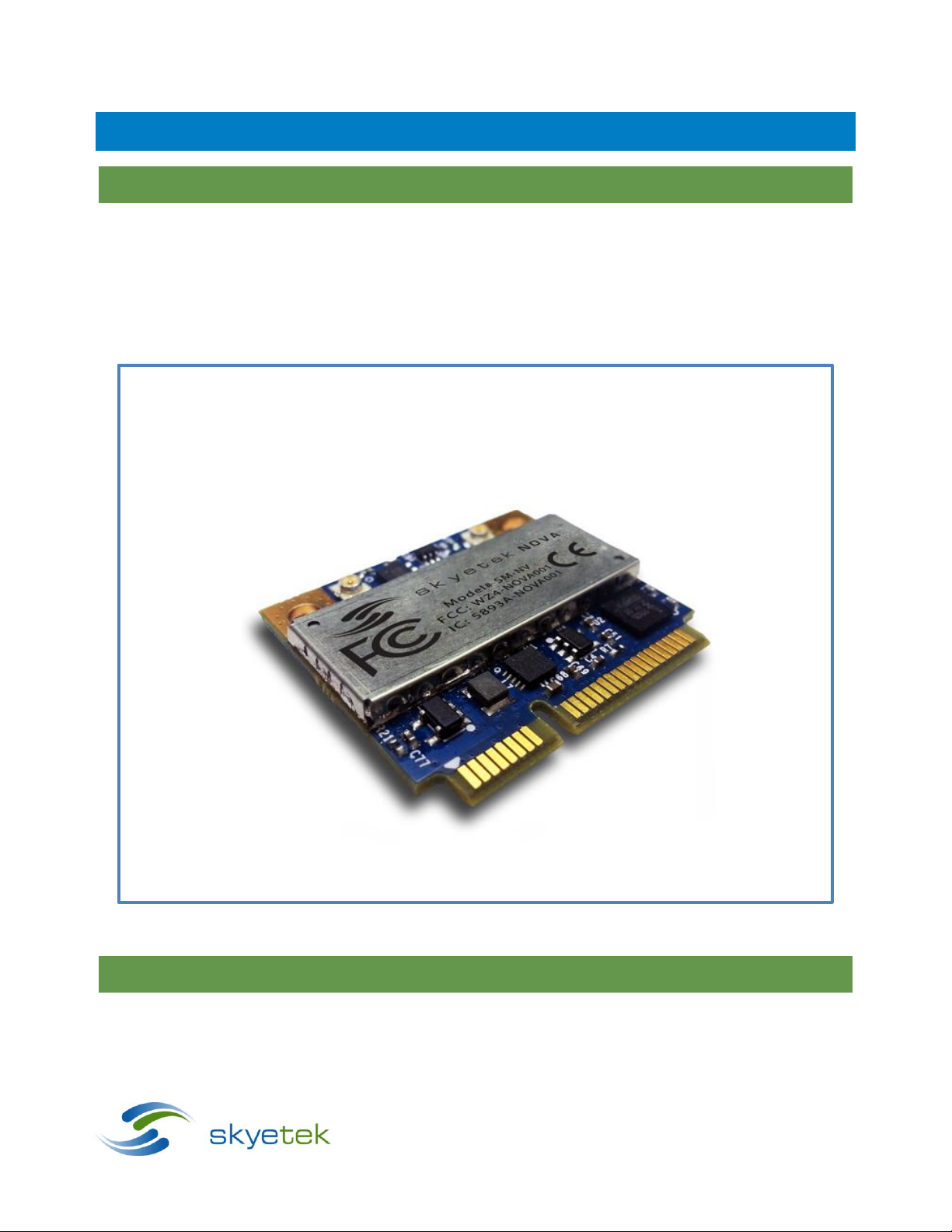
4.1 Description
The SkyeModule™ Nova marks the next generation of SkyeTek UHF reader modules. The Nova is an ultrasmall, 2 port, 500mW EPC Class 1 Gen 2 reader/writer module. A cutting edge ARM Cortex microcontroller,
latest UHF transceiver technology and cutting edge adaptive antenna tuning coupled with the reader's
intelligent operating system make this module the most powerful and feature rich UHF reader module of its
size. Manufactured in accordance with ISO 9001 and ISO 13485, quality is a top priority for all SkyeTek
modules.
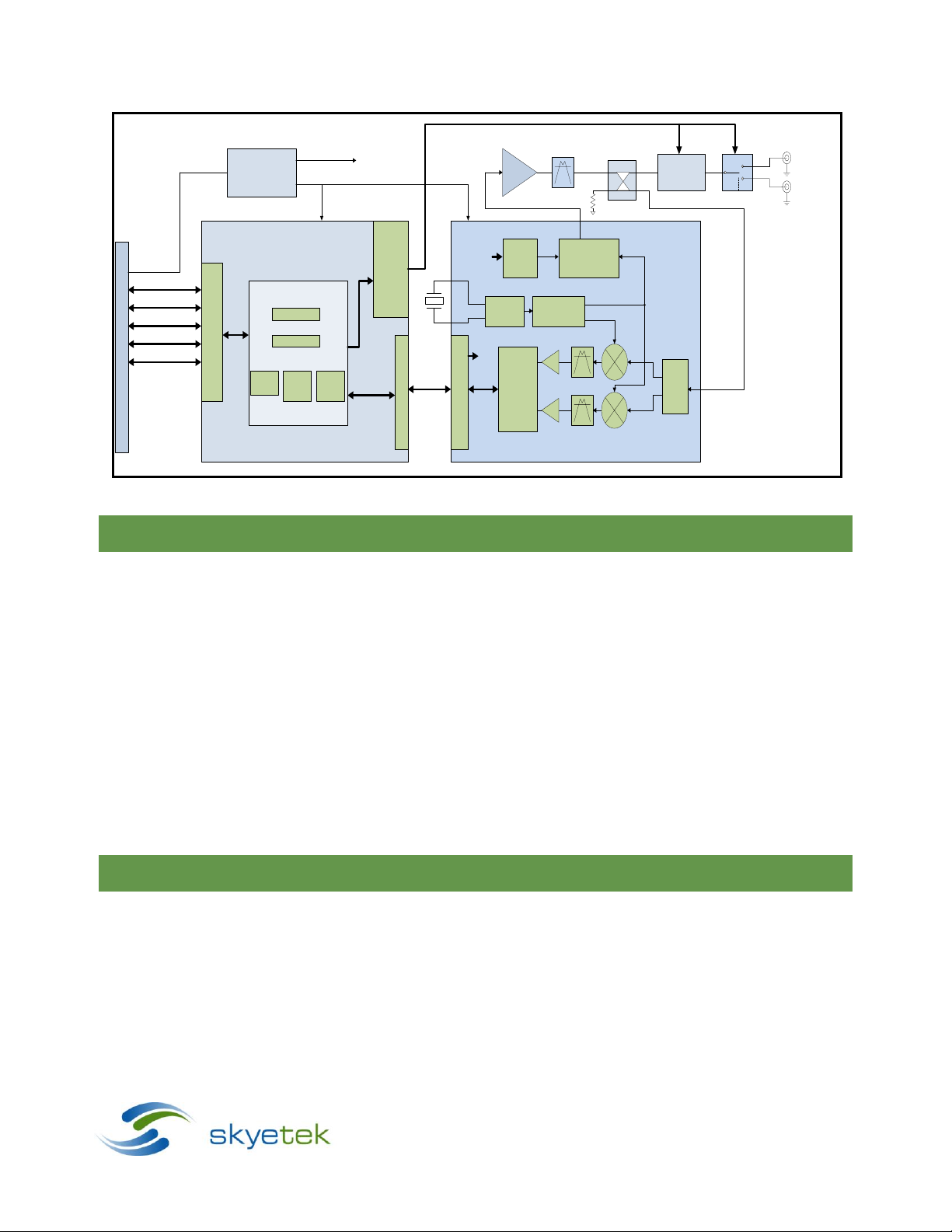
4.2 Block Diagram
Figure 4-1: SM-NV
SkyeModule Nova Datasheet - Preliminary Page | 11
Skyetek Inc
1732 Wazee St. Ste 202
Denver, CO 80202
www.skyetek.com
Main 720.328.3425 Fax:720.228.2400
Antenna
Tuner
Power
Regulation
IN
OUT
ISOL
CPLD
ARM CORTEX M0 MICRO
ANT A
PCIe Connector
USB
SPI_0
UART
12C
GPIO(4)
ANT B
RF
Synthesizer
LO I
LO Q
Power
Divider
RX
Detector
and
Framing
Logic
MCU Interface
Clock
Logic
TX
Framing
TX
Modulator
Baseband Filter
TX RF
ANT SEL
RX RF
AS3993
Radio IC Drivers
Skye OS
Protocol Parser
Tag Commands
Crypto
Libraries
ISO
Protocol
Libraries
Tag
Feature
Libraries
RF PA
Interface Drivers
TX
TX
Radio Control
Drivers
Vin
RF
RF BPF
Coupler
Figure 4-2: SkyeModule Nova Block Diagram
4.3 Features
Selects, Reads and writes to transponders based on EPC Global Class 1 Gen 2v2 (ISO 18000-6C)
2 antenna ports, each capable of 500mW output power
Adaptive Antenna Tuning
Can operate from 500mA USB port
Modular certification for USA and Canada
CE Mark
Mini PCIe half card form factor
Wide and efficient power supply with input from 2.5 – 5.5V
Deep sleep mode current down to 10uA
Easy migration from the SkyeModules M7/M9/M10
Supported host interfaces include USB, TTL level RS232, SPI, I2C
Return Signal Strength Indicator (RSSI)
4.4 Applications
Mobile Computing
Inventory and Asset Management
o Retail Inventory
o In Transit Inventory
Access Control
SkyeModule Nova Datasheet - Preliminary Page | 12
Skyetek Inc
1732 Wazee St. Ste 202
Denver, CO 80202
www.skyetek.com
Main 720.328.3425 Fax:720.228.2400
4.5 Agency Approvals
RoHS 2
FCC Modular
IC Modular
CE Mark
UL
Manufactured according to ISO9001 and ISO13485
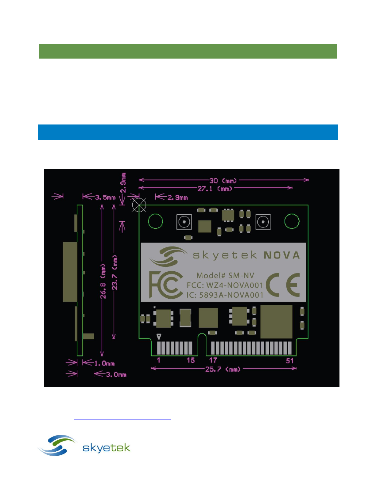
5 Mechanical Specif ications
Dimensions: 26.8 mm x 30 mm = 804mm
Height: 5.5 mm
2
Note that the Nova complies with the PCI Express (PCIe) Mini form factor. Detailed information on this standard is
available at https://www.pcisig.com/specifications. Mating board edge connectors are available from numerous
vendors including JAE, Molex and TE connectivity (see table below). The pin numbering convention is shown in the
Figure 5-1: SM-NV Mechanical Drawing

SkyeModule Nova Datasheet - Preliminary Page | 13
Skyetek Inc
1732 Wazee St. Ste 202
Denver, CO 80202
www.skyetek.com
Main 720.328.3425 Fax:720.228.2400
Nova Connector
Description
Ref Des
Man.
Mating Connector
Notes
52 pin Mini PCIe
Host interface
connector
J1
Molex
0679101002
JAE
MM60-52B1-G1-R850
TE Connectivity
1717831-1
U.FL Jack
Antenna Connector
(Port0, Port1)
J2, J3
Taoglas
CAB.011
U.FL to SMA
Digi International
JF1R6-CR3041
U.FL to SMA
drawing above, with odd numbered pins on the top, and even numbered pins on the bottom of the board. Pin 2 is
directly below pin 1. Pinning Information
5.1 Connector Descriptions
The SM-NV-00 is the standard version of the Nova module and uses the 52 pin Mini PCIe connector In addition, the
Nova features two antenna ports that connect via U.FL connectors. A sampling of mating connectors is listed
below:
Table 5-1: SkyeModule Nova Connector Recommendations
5.2 Host Interface Connector Pin Mapping
The SkyeModule Nova host connector is a 52-pin Mini PCI Express edge connector. The pin numbers are located as
illustrated in Figure 5-2 above. The pin mappings and descriptions are shown in Error! Reference source not
found.. Note that all unconnected pins should be left floating.

SkyeModule Nova Datasheet - Preliminary Page | 14
Skyetek Inc
1732 Wazee St. Ste 202
Denver, CO 80202
www.skyetek.com
Main 720.328.3425 Fax:720.228.2400
Pin
Name
Description
I/O
Pin
Name
Description
I/O 1 NC
Not Connected
N/A 2 VIN
Input Power Supply
Input
3
NC
Not Connected
N/A 4 GND
Ground
Input
5
NC
Not Connected
N/A 6 NC
Not Connected
N/A 7 NC
Not Connected
N/A 8 MISO
SPI Master In, Slave Out
Output
9
GND
Ground
Input
10
MOSI
SPI Master Out, Slave In
Input
11
NC
Not Connected
N/A
12
SCK
SPI Clock IN
Input
13
NC
Not Connected
N/A
14
SSEL
SPI Slave Select
Input
15
GND
Ground
Input
16
NC
Not Connected
N/A
17
NC
Not Connected
N/A
18
GND
Ground
Input
19
NC
Not Connected
N/A
20
Deep Sleep
Active Low Deep Sleep
Input
21
GND
Ground
Input
22
Reset
Active Low Reset
Input
23
NC
Not Connected
N/A
24
VIN
Input Power Supply
Input
25
NC
Not Connected
N/A
26
GND
Ground
Input
27
GND
Ground
Input
28
NC
Not Connected
N/A
29
GND
Ground
Input
30
SCL
I2C Clock
Input
31
NC
Not Connected
N/A
32
SDA
I2C Data
I/O
33
NC
Not Connected
N/A
34
GND
Ground
Input
35
GND
Ground
Input
36
D-
USB D minus
I/O
37
GND
Ground
Input
38
D +
USB D Plus
I/O
39
VIN
Input Power Supply
Input
40
GND
Ground
Input
41
VIN
Input Power Supply
Input
42
GPIO0
General Purpose I/O 0
I/O
43
GND
Ground
Input
44
GPIO1
General Purpose I/O 1
I/O
45
GPIO3
General Purpose I/O 3
I/O
46
GPIO2
General Purpose I/O 2
I/O
47
NC
Not Connected
N/A
48
NC
Not Connected
N/A
49
RXD
UART Receive
Input
50
GND
Ground
Input
51
TXD
UART Transmit
Output
52
VIN
Input Power Supply
Input
Figure 5-2: Host Interface Connector Pin Numbering
5.3 Using the GPIO Pins
You can use the User Port Direction and User Port Value system parameters to address the GPIO pins to set
the user port direction (input or output) and the user port value (high or low). For more information, see
the following:
“User Port Direction” in section 13.3.9
“User Port Value” in section 13.3.10
NOTE – GPIO3 is used as a data ready pin when in SPI or I2C mode. GPIO3 cannot be used as GPIO when using
these interfaces.
 Loading...