

JADAK a business unit of Novanta GEMINI003 User Manual
SKYEMODULE GEMINI DATASHEET
VERSION 051214

SkyeModule Gemini Datasheet Page | 2
Skyetek Inc
1732 Wazee St. Ste 202
Denver, CO 80202
www.skyetek.com
Main 720.328.3425 Fax:720.228.2400
COPYRIGHT INFORMATION:
Copyright 2014 SkyeTek, Inc., 1732 Wazee St. Suite 202, Denver, Colorado 80202, U.S.A. All rights reserved.
Version 051214
This product or document is protected by copyright and distributed under licenses restricting its use, copying, distribution, and decompilation. No
part of this product or document may be reproduced in any form by any means without prior written authorization of SkyeTek and its licensors, if
any.
SkyeTek and SkyeWare are trademarks or registered trademarks of SkyeTek, Inc.
MIFARE and NXP is a registered trademark of Royal Philips Electronics.
MicroSoft and Windows are re gistered trademarks of Microsoft Corporation.
TECHNICAL SUPPORT AND CONTACT INFORMATION
SkyeTek, Inc.
1732 Wazee St. Suite 202
Denver, CO 80202
http://www.skyetek.com
SALES:
sales@skyetek.com
TECHNICAL SUPPORT:
support@skyetek.com

SkyeModule Gemini Datasheet Page | 3
Skyetek Inc
1732 Wazee St. Ste 202
Denver, CO 80202
www.skyetek.com
Main 720.328.3425 Fax:720.228.2400
TABLE OF CONTENTS
1 INTRODUCTION .............................................................................................................................................. 7
1.1 GETTING STARTED .............................................................................................................................................. 7
1.2 WHY A SKYETEK MODULE? .................................................................................................................................. 7
1.3 ADDITIONAL READING ......................................................................................................................................... 8
1.4 REVISION HISTORY .............................................................................................................................................. 9
2 DEFINITION OF TERMS ................................................................................................................................. 10
3 ORDERING INFORMATION ........................................................................................................................... 11
3.1 GEMINI STANDARD PART NUMBERS ..................................................................................................................... 11
3.2 PART NUMBER DETAILS ..................................................................................................................................... 11
3.3 HOW TO BUY ................................................................................................................................................... 12
4 SKYEMODULE GEMINI OVERVIEW ................................................................................................................ 13
4.1 D
4.2 BLOCK DIAGRAM .............................................................................................................................................. 13
4.3 FEATURES ........................................................................................................................................................ 14
4.4 APPLICATIONS .................................................................................................................................................. 14
4.5 AGENCY APPROVALS ......................................................................................................................................... 14
5 MECHANICAL SPECIFICATIONS ..................................................................................................................... 15
6 PINNING INFORMATION .............................................................................................................................. 16
6.1 CONNECTOR DESCRIPTIONS ................................................................................................................................ 16
6.2 HOST INTERFACE CONNECTOR PIN MAPPING ......................................................................................................... 17
6.3 EXTERNAL ANTENNA CONNECTOR PIN MAPPING .................................................................................................... 18
6.4 USING THE GPIO PINS ...................................................................................................................................... 19
7 ENVIRONMENTAL SPECIFICATIONS .............................................................................................................. 20
7.1 ELECTROSTATIC PRECAUTIONS ............................................................................................................................. 20
7.2 GENERAL RATINGS AND OPERATING CONDITIONS ................................................................................................... 20
8 ELECTRICAL SPECIFICATIONS ........................................................................................................................ 21
8.1 ELECTRICAL CHARACTERISTICS ............................................................................................................................. 21
8.2 ABSOLUTE MAXIMUM RATINGS ........................................................................................................................... 22
9 PERFORMANCE SPECIFICATIONS .................................................................................................................. 23
ESCRIPTION
.................................................................................................................................................. 13
9.1 TIMING SPECIFICATIONS ..................................................................................................................................... 23
9.2 RANGE SPECIFICATIONS...................................................................................................................................... 24
10 RADIO SPECIFICATIONS ............................................................................................................................ 25
10.1 AGENCY APPROVALS ......................................................................................................................................... 25
10.2 HOST DEVICE LABELING FOR FCC ........................................................................................................................ 25

SkyeModule Gemini Datasheet Page | 4
Skyetek Inc
1732 Wazee St. Ste 202
Denver, CO 80202
www.skyetek.com
Main 720.328.3425 Fax:720.228.2400
10.3 FREQUENCY BAND ............................................................................................................................................ 25
10.4 TAG PROTOCOLS .............................................................................................................................................. 25
11 HOST INTERFACE SPECIFICATIONS ............................................................................................................ 26
11.1 USB 2.0 ......................................................................................................................................................... 27
11.2 TTL SERIAL ...................................................................................................................................................... 28
11.3 SPI ................................................................................................................................................................ 30
11.4 I2C ................................................................................................................................................................. 33
12 SKYEMODULE GEMINI ANTENNA OPTIONS .............................................................................................. 36
13 COMMUNICATING WITH THE MODULE .................................................................................................... 37
13.1 HOST COMMUNICATION (SKYETEK PROTOCOL V3).................................................................................................. 37
13.2 REQUEST FORMATS ........................................................................................................................................... 37
13.3 RESPONSE FORMATS ......................................................................................................................................... 38
14 SYSTEM PARAMETERS .............................................................................................................................. 39
14.1
S
YSTEM PARAMETER SUMMARY
.................................................................................................................. 39
14.2 CHANGING SYSTEM PARAMETERS ........................................................................................................................ 39
14.3 SYSTEM PARAMETER DETAILS.............................................................................................................................. 40
15 SPECIAL FEATURES
.................................................................................................................................. 44
15.1 SLEEP MODES .................................................................................................................................................. 44
15.2 FEATURE REQUESTS .......................................................................................................................................... 44

SkyeModule Gemini Datasheet Page | 5
Skyetek Inc
1732 Wazee St. Ste 202
Denver, CO 80202
www.skyetek.com
Main 720.328.3425 Fax:720.228.2400
LIST OF FIGURES
Figure 3-1: SkyeTek Part Number Format ........................................................................................... 11
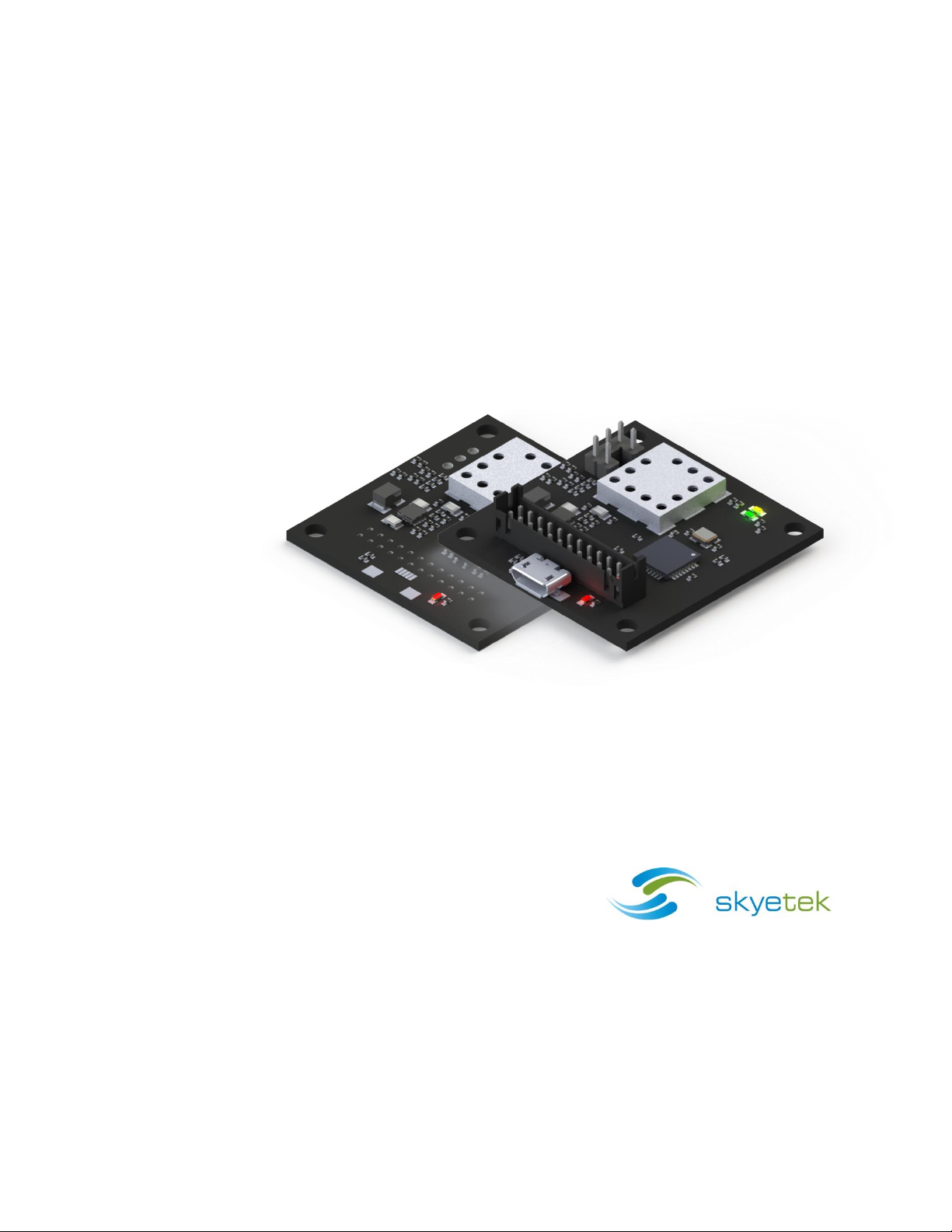
Figure 4-1: SM-GM-AC (with all connectors) ....................................................................................... 13
Figure 4-2: SkyeModule Gemini Block Diagram ................................................................................... 13
Figure 5-1: SM-GM Mechanical Drawing ............................................................................................. 15
Figure 6-1: Host Interface Connector Pin Numbering ........................................................................... 17
Figure 6-2: External Antenna Pin Numbering ...................................................................................... 18
Figure 9-1: Tag Command Execution Time Measurement .................................................................... 23
Figure 9-2: Range Specifications ........................................................................................................ 24
Figure 11-1: USB Connection Diagram ................................................................................................ 27
Figure 11-2: TTL Serial Connection Diagram ....................................................................................... 28
Figure 11-3: TTL Serial Timing Diagram ............................................................................................. 29
Figure 11-4: SPI Connection Diagram ................................................................................................. 30
Figure 11-5: SPI Request Setup and Sample Timing ............................................................................ 31
Figure 11-6: SPI Request Timing........................................................................................................ 31
Figure 11-7: SPI Response Timing ..................................................................................................... 32
Figure 11-8: I2C Connection Diagram ................................................................................................. 33
Figure 11-9: I2C Timing Diagram ........................................................................................................ 35

SkyeModule Gemini Datasheet Page | 6
Skyetek Inc
1732 Wazee St. Ste 202
Denver, CO 80202
www.skyetek.com
Main 720.328.3425 Fax:720.228.2400
LIST OF TABLES
Table 1-1: Revision History .................................................................................................................. 9
Table 3-1: Gemini Standard Part Numbers .......................................................................................... 11
Table 3-2: Part Number Details .......................................................................................................... 11
Table 6-1: SkyeModule Gemini Connector Specification ....................................................................... 16
Table 6-2: SkyeModule Gemini Pin Descriptions .................................................................................. 17
Table 6-3: External Antenna Pin Descriptions ...................................................................................... 18
Table 7-1: Environmental Ratings/Operating Conditions ...................................................................... 20
Table 8-1: SkyeModule Gemini Electrical Specifications ........................................................................ 21
Table 8-2: Absolute Maximum Ratings ................................................................................................ 22
Table 9-1: Timing Specifications ........................................................................................................ 23
Table 13-1: Request Format (bytes), ASCII Mode ............................................................................... 37
Table 13-2: Request Format (bytes), Binary Mode .............................................................................. 37
Table 13-3: Response Format (bytes), Binary Mode ............................................................................ 38
Table 14-1: SkyeModule Gemini System Parameters ........................................................................... 39

SkyeModule Gemini Datasheet Page | 7
Skyetek Inc
1732 Wazee St. Ste 202
Denver, CO 80202
www.skyetek.com
Main 720.328.3425 Fax:720.228.2400
1 Introduction
1.1 Getting Started
Operating your SkyeModule Gemini begins with finding a method to connect to a host. The
SkyeModule itself does not operate without direction (commands) from a host. The host can be in the
form of a PC or, more typically, an embedded microcontroller. This document explains the physical and
electrical characteristics of the module, so you can understand how to integrate the Gemini into a
finished product.
For initial demonstration of the module, SkyeWare v4 software is available on the media that came
with the developer/evaluation kit or available for download at support.skyetek.com. Open this software
on your windows PC and it will be recognized when you connect through USB or RS232 (with developer
kit interface board). The software demonstrates features like selecting tags, reading and writing. It also
has a powerful command builder that lets you format, send and receive any command to and from the
reader. More about SkyeWare can be found in the SkyeWare User Guide. See the Additional Reading
section below.
The next step after demonstrating the module’s functionality is developing your own
communication with the module. This can be achieved with simple code on a microcontroller or
using the SkyeTek API on a PC. Once connected to a host through one of the four host interfaces, the
reader to host communication is formatted with a full featured protocol called SkyeTek Protovol v3. In
order to make learning commands and formatting easy, we have developed a series of application notes
with examples to get you started. The application notes start with basic tag and reader commands and
become very detailed for tags with special features. Read more about the protocol and commands in
section 13, Communicating with the Module and then move on to the Additional Reading in section 1.3.
1.2 Why a SkyeTek Module?
Many customers may wonder, “What value does a module add over an RFID transceiver chip?”
RFID transceiver chips may seem simple, but they actually require significant engineering time and
capital investment to integrate. Transceiver chips contain up to 50 registers for configuration and
functionality. In addition, communicating over air protocols such as ISO14443 is complex, described in
nearly 150 pages of cryptic procedures. For example, just selecting a tag requires a minimum of 6 and up
to 100 over air interactions with multiple tags present. SkyeTek modules mask the complexities of
RFID from the user and pack functionality into just a few commands.
SkyeTek’s core set of commands allow the user to read and write to tags with a single command,
regardless of the tag type. The Gemini handles complex cryptography, which many modules lack, to
easily add more security for access control or payment systems. The module is also field upgradable, so
you can use the latest security algorithms and tag features as they are released. Power regulation and
filtering for the radio are handled in the Gemini, so you can supply voltage directly from an unregulated

SkyeModule Gemini Datasheet Page | 8
Skyetek Inc
1732 Wazee St. Ste 202
Denver, CO 80202
www.skyetek.com
Main 720.328.3425 Fax:720.228.2400
source like a battery. Finally, the Gemini will be modularly approved by the FCC and CE, so you can
bypass expensive radio testing at a certified test lab and avoid potential schedule delays due to failures.
Using a SkyeTek module will greatly reduce time to market and upfront development costs.
Allow SkyeTek to take the burden of developing an RF system so you can focus your energy on your core
products.
1.3 Additional Reading
Gemini Tag Support Matrix – List of supported tags and commands supported with those tags
Gemini Basic Tag Commands – Application note with descriptions and examples of the basic tag
commands: select tag, read tag, and write tag
SkyeTek Protocol v3 Reader Commands – Application note with descriptions and examples of the reader
commands: read/write system, read/write default system, load defaults, and reset
Keyboard Wedge Operating Mode - This application note describes the Gemini functionality in keyboard
wedge mode and also how to enter and exit this mode. Keyboard wedge mode can be very handy when
replacing a barcode scanner or when minimal software integration is desired.
Using MIFARE Classic – Application note with information on the tag and memory structure as well as the
protocol commands to support special features of this tag like crypto authentication.
Using MIFARE Ultralight C – Application note with information on the tag and memory structure as well
as the protocol commands to support special features of this tag like authentication and locking.
Using MIFARE Plus – Application note with information on the tag’s memory structure and security levels.
It also includes examples of protocol commands to support the special features of this tag like initializing
security and Crypto1/AES authentication and MACing.
Kovio NFC Barcode and 2K – Application note with information on the tag and memory structure as well
as the protocol commands to support special features of these tags like locking.
SkyeTek Protocol v3 Guide – A quick protocol reference for command structure if you already know the
command you want to use. This is also a good reference for error codes and tag type codes.

SkyeModule Gemini Datasheet Page | 9
Skyetek Inc
1732 Wazee St. Ste 202
Denver, CO 80202
www.skyetek.com
Main 720.328.3425 Fax:720.228.2400
Revision
Author
Change
040913
Brad Alcorn
Initial draft.
111313
Brad Alcorn
Updates for v3.0 hardware and firmware version 0101053.
013114
Brad Alcorn
Minor update to part numbering.
051214
Brad Alcorn
Updates for FCC certification.
1.4 Revision History
Table 1-1: Revision History

SkyeModule Gemini Datasheet Page | 10
Skyetek Inc
1732 Wazee St. Ste 202
Denver, CO 80202
www.skyetek.com
Main 720.328.3425 Fax:720.228.2400
3DES
Triple Data Encryption Standard
AES
Advanced Encryption Standard
API
Application Programming Interface
DES
Data Encryption Standard
GPIO
General Purpose Input/Output
HID
Human Interface Device
I2C
Inter-integrated Circuit
LSB
Least Significant Bit
MSB
Most Significant Bit
NC
No Connect
RoHS
Reduction of Hazardous Substances
SPI
Serial Peripheral Interface
SSEL
Slave Select
STP V3
SkyeTek Protocol Version 3
TTL
Transistor-transistor Logic
2 Definitio n of Terms

SkyeModule Gemini Datasheet Page | 11
Skyetek Inc
1732 Wazee St. Ste 202
Denver, CO 80202
www.skyetek.com
Main 720.328.3425 Fax:720.228.2400
Part Number
Host Interface
Baud Rate
Description
SM-GM-UB
TTL Serial
38400 Baud
USB connector only.
SM-GM-MH
TTL Serial
38400 Baud
USB and board to board connector populated.
SM-GM-AC
TTL Serial
38400 Baud
All connectors populated. See Figure 4-1.
PF-PT-BT-OPTS
Product Family
Product Type
Build Type
Options
Code
Options
Description
Product Family
SM = SkyeModule
Highest level product family code.
Product Type
GM = Gemini
Specifies the specific part type.
Build Type
UB = USB connector only
MH = With USB and MH connectors
AC = All connectors
Specifies hardware form factor.
Options
Blank = Standard
This field is left for special customer part numbers or standard
variations such I2C for I2C as the default host interface. Consult the
SkyeTek sales team for custom orders.
3 Ordering Information
3.1 Gemini Standard Part Numbers
Table 3-1: Gemini Standard Part Numbers
NOTE – The Gemini will always communicate via USB, when a USB host is connected.
NOTE – See section 6.1 for more information on the Gemini connectors.
3.2 Part Number Details
The Gemini part number is constructed according to the SkyeTek part number specification below:
Figure 3-1: SkyeTek Part Number Format
Table 3-2: Part Number Details

SkyeModule Gemini Datasheet Page | 12
Skyetek Inc
1732 Wazee St. Ste 202
Denver, CO 80202
www.skyetek.com
Main 720.328.3425 Fax:720.228.2400
3.3 How to Buy
SkyeTek products are distributed through a worldwide distribution network as well as directly through
SkyeTek. For more information on how to purchase SkyeTek products in your area, please visit the How
To Buy page on the SkyeTek website at SkyeTek.com/HowToBuy.

SkyeModule Gemini Datasheet Page | 13
Skyetek Inc
1732 Wazee St. Ste 202
Denver, CO 80202
www.skyetek.com
Main 720.328.3425 Fax:720.228.2400
Cortex M-0 Microcontroller Firmware
SkyeOS
SkyeModule Gemini
USB ConnectorHost Interface Connector
Interface Drivers
Protocol Parser
Tag Commands
System
Parameters
Crypto
Libraries
ISO
Protocol
Libraries
Tag
Feature
Libraries
Radio Drivers
Radio
Transceiver
TRX LED
MCU LED
JumpersEMC Filter
Matching
Network
Integrated Antenna
External
Antenna
Connector
Power Regulation
VIN (1.8 – 5.5V)
TTL Serial
SPI
I2C
USB
VCC (3.3V)
4 SkyeModule Gemini Overview
4.1 Description
The SkyeModule™ Gemini marks the next generation of SkyeTek HF reader modules. The Gemini is
a low-cost, and ultra-low power, ISO14443 MIFARE and NFC reader/writer module. A cutting edge
ARM Cortex microcontroller and latest HF transceiver technology coupled with the reader's intelligent
operating system make this module the most versatile HF RFID module at the bottom tier price
point. Manufactured in accordance with ISO 9001 and ISO 13485, quality is a top priority for all
SkyeTek modules.
4.2 Block Diagram
Figure 4-1: SM-GM-AC (with all connectors)
Figure 4-2: SkyeModule Gemini Block Diagram

SkyeModule Gemini Datasheet Page | 14
Skyetek Inc
1732 Wazee St. Ste 202
Denver, CO 80202
www.skyetek.com
Main 720.328.3425 Fax:720.228.2400
4.3 Features
Reads and writes to transponders based on ISO14443A/B
Reads and writes to other NFC devices based on ISO18092 peer-to-peer (coming soon)
Emulates NFC tags based on ISO18092 (coming soon)
3DES authentication for MIFARE Ultralight C tags (coming soon)
AES128 authentication and MAC for MIFARE Plus tags
Crypto1 authentication for MIFARE Classic and Plus tags
Wide and efficient power supply with input from 2.0 – 5.5V
Deep sleep mode current down to 10uA
Easy migration to and from the M2/M4
Supported host interfaces include USB, TTL level RS232, SPI, I2C
Integrated internal antenna and options to use external antennas
Modularly certified (coming soon)
4.4 Applications
NFC Bluetooth pairing
NFC Games
Access control
Loyalty Card Reader
Ticketing
Transportation Fare
Kiosks
Product and Consumable Anti-Counterfeiting
RFID Printers
ATMs
Vending Machines
Debiting Systems
4.5 Agency Approvals
RoHS 2
FCC Modular
CE Mark – Seeking approval
Manufactured according to ISO9001 and ISO13485
 Loading...