

Jacuzzi BELLAVISTA 5, ALLUSION 6636, ALLUSION 7236, ALLUSION 7242, BELLAVISTA 6 Installation & Operation Instructions
...Page 1

DESIGNER/LUXURY BATH SERIES
INSTALLATION / OPERA TION INSTRUCTIONS
Save These Instructions for Future Use.
Complete and mail-in the product registration card provided with your unit.
Write and save the model and serial number of your unit below.
Owner's Record
Date Purchased ____________________________________________________________
Purchased From ____________________________________________________________
Installed By ________________________________________________________________
Serial Number _____________________________________________________________
Model ____________________________________________________________________
Installer: Leave this manual for homeowner.
Homeowner: Read this manual and keep for future reference.
©
2005 Jacuzzi Whirlpool Bath K339000X 3/06
Page 2

IMPORTANT SAFETY INSTRUCTIONS
READ AND FOLLOW ALL INSTRUCTIONS
SAVE THESE INSTRUCTIONS
ENGLISH
INSTRUCTIONS PERTAINING TO A RISK OF FIRE, ELECTRIC
SHOCK, OR INJURY TO PERSONS
WARNING — WHEN USING THIS UNIT, BASIC PRECAUTIONS SHOULD AL WAYS BE FOLLOWED,
INCLUDING THE FOLLOWING:
DANGER: — TO REDUCE THE RISK OF INJURY, DO NOT PERMIT CHILDREN TO USE THIS UNIT
UNLESS THEY ARE CLOSEL Y SUPERVISED A T ALL TIMES.
WARNING — USE THIS UNIT ONL Y FOR ITS INTENDED USE AS DESCRIBED IN THIS MANUAL. DO
NOT USE ATTACHMENTS NOT RECOMMENDED BY THE MANUFACTURER.
WARNING — NEVER DROP OR INSERT ANY OBJECT INTO ANY OPENING .
WARNING — DO NOT OPERATE THIS UNIT WITHOUT THE GUARD OVER THE SUCTION FITTING.
WARNING — THIS UNIT MUST BE CONNECTED ONLY TO A SUPPLY CIRCUIT THAT IS PROTECTED
BY A GROUND FAULT CIRCUIT INTERRUPTER (GFCI). SUCH A GFCI SHOULD BE PROVIDED BY
THE INSTALLER AND SHOULD BE TESTED ON A ROUTINE BASIS. TO TEST THE GFCI, PUSH THE
TEST BUTTON. THE GFCI SHOULD INTERRUPT POWER. PUSH THE RESET BUTTON. POWER
SHOULD BE RESTORED. IF THE GFCI FAILS TO OPERATE IN THIS MANNER, THE GFCI IS
DEFECTIVE. IF THE GFCI INTERRUPTS POWER TO THE BATHTUB WITHOUT THE TEST BUTTON
BEING PUSHED, A GROUND CURRENT FLOWING, INDICATING A POSSIBILITY OF AN ELECTRIC
SHOCK. DO NOT USE THIS HYDROMASSAGE BATHTUB. DISCONNECT THE HYDROMASSAGE
BATHTUB AND HAVE THE PROBLEM CORRECTED BY A QUALIFIED SERVICE REPRESENTATIVE
BEFORE USING.
WARNING — (FOR PERMANENTLY CONNECTED UNITS) A GREEN COLORED TERMINAL (OR A WIRE
CONNECTOR MARKED “G”, “GR”, “GROUND”, OR “GROUNDING”) IS PROVIDED WITHIN THE TERMINAL
COMPARTMENT. TO REDUCE THE RISK OF ELECTRIC SHOCK, CONNECT THE TERMINAL OR
CONNECTOR TO THE GROUNDING TERMINAL OF YOUR ELECTRIC SERVICE OR SUPPLY PANEL WITH
A CONDUCTOR EQUIVALENT IN SIZE TO THE CIRCUIT CONDUCTORS SUPPLYING THIS EQUIPMENT.
OPERATING
WARNING — PROLONGED IMMERSION IN HOT WATER MAY INDUCE HYPERTHERMIA. HYPER-
THERMIA OCCURS WHEN THE INTERNAL TEMPERA TURE OF THE BODY REACHES A LEVEL SEV ERAL DEGREES ABOVE THE NORMAL BODY TEMPERATURE OF 98.6°F. THE SYMPTOMS OF
HYPERTHERMIA INCLUDE AN INCREASE IN THE INTERNAL TEMPERATURE OF THE BODY, DIZZINESS, LETHARGY, DROWSINESS AND FAINTING. THE EFFECTS OF HYPERTHERMIA INCLUDE:
A) FAILURE TO PERCEIVE HEAT
B) FAILURE TO RECOGNIZE THE NEED TO EXIT THE SPA OR HOT TUB,
C) UNAWARENESS OF IMPENDING HAZARD,
D) FETAL DAMAGE IN PREGNANT WOMEN,
E) PHYSICAL INABILITY TO EXIT THE SPA OR HOT TUB, AND
F) UNCONSCIOUSNESS RESULTING IN DANGER OF DROWNING.
WARNING — THE USE OF ALCOHOL, DRUGS OR MEDICATION CAN GREATLY INCREASE THE
RISK OF FATAL HYPERTHERMIA.
WARNING — DO NOT TAMPER WITH USER-OPERATED CONTROLS OR SUCH DEVICES.
2
Jacuzzi Whirlpool Bath K339000X 3/06
Page 3

INST ALLATION INSTRUCTIONS
WARNING — WHEN USING THIS UNIT, BASIC PRECAUTIONS SHOULD ALWAYS BE FOLLOWED,
INCLUDING THE FOLLOWING:
DANGER — RISK OF ELECTRIC SHOCK. CONNECT ONLY TO A CIRCUIT PROTECTED BY A GROUND
FAULT CIRCUIT INTERRUPTER (GFCI).
CAUTION — TEST THE GROUND FAULT CIRCUIT INTERRUPTER PROTECTING THIS APPLIANCE
PERIODICALLY IN ACCORDANCE WITH MANUFACTURER’S INSTRUCTIONS.
WARNING — USE THIS UNIT ONLY FOR ITS INTENDED USE AS DESCRIBED IN THIS MANUAL. DO NOT
USE ATTACHMENTS NOT RECOMMENDED BY THE MANUFACTURERS.
WARNING — TO AVOID INJURY, EXERCISE CAUTION WHEN ENTERING OR EXITING THE HYDROMASSAGE BATHTUB.
WARNING — KEEP BODY AND HAIR A MINIMUM OF 6" (15,2 cm) AWAY FROM SUCTION FITTING AT ALL
TIMES WHEN THE HYDROMASSAGE SYSTEM IS OPERATING. HAIR LONGER THAN SHOULDER
LENGTH SHOULD BE SECURED CLOSE TO THE HEAD.
WARNING — RISK OF ELECTRICAL SHOCK; DO NOT PERMIT ELECTRICAL APPLIANCES (SUCH AS HAIR
DRYER, LAMP, TELEPHONE, RADIO OR TELEVISION) WITHIN 60" (1,5 M) OF THIS HYDROMASSAGE BATHTUB.
WARNING — RISK OF ACCIDENTAL INJURY OR DROWNING; DO NOT USE DRUGS OR ALCOHOL
BEFORE OR DURING THE USE OF HYDROMASSAGE BATHTUB EQUIPPED WITH A HEATER TO AVOID
UNCONSCIOUSNESS AND POSSIBLE DROWNING.
WARNING — RISK OF FETAL INJURY; PREGNANT OR POSSIBLY PREGNANT WOMEN SHOULD
CONSULT A PHYSICIAN BEFORE USING A HYDROMASSAGE BATHTUB EQUIPPED WITH A HEATER.
WARNING — RISK OF HYPERTHERMIA AND POSSIBLE DROWNING; DO NOT USE A HYDROMASSAGE
BATHTUB EQUIPPED WITH A HEATER IMMEDIATELY FOLLOWING STRENUOUS EXERCISE.
WARNING — RISK OF HYPERTHERMIA AND POSSIBLE DROWNING; WATER TEMPERATURE IN
EXCESS OF 104°F (40°C) MAY BE INJURIOUS TO YOUR HEALTH. CHECK AND ADJUST WATER
TEMPERATURE BEFORE USE.
WARNING — RISK OF HYPERTHERMIA; PEOPLE USING MEDICATIONS AND/OR HAVING AN ADVERSE
MEDICAL HISTORY SHOULD CONSULT A PHYSICIAN BEFORE USING A HYDROMASSAGE BATHTUB
EQUIPPED WITH A HEATER.
ENGLISH
FOR BUILT-IN AND DROP-IN UNITS, INSTALL TO PERMIT ACCESS FOR SERVICING.
THIS UNIT SHOULD BE ELECTRICALLY GROUNDED AND INSTALLED BY A LICENSED CONTRACTOR, ELECTRICIAN, AND PLUMBER.
BUILDING MATERIALS AND WIRING SHOULD BE ROUTED AWAY FROM THE MOTOR/PUMP OR
BLOWER OR OTHER HEAT PRODUCING COMPONENTS OF THIS UNIT.
A PRESSURE WIRE CONNECTOR IS PROVIDED ON THE EXTERIOR OF THE MOTOR/PUMP AND
HEATER TO PERMIT CONNECTION OF AN NO. 8 AWG (8.4 MM) SOLID COPPER BONDING CONDUCTOR
BETWEEN THIS UNIT AND ALL OTHER ELECTRIC EQUIPMENT AND EXPOSED METAL IN THE VICINITY,
AS NEEDED TO COMPLY WITH LOCAL REQUIREMENTS.
PRECAUTIONS
••
• Do not operate the hydromassage system unless the bath is filled with water to at least 1" to 2" (2,5 - 5,08 cm) above the
••
highest jet.
••
• Do not immerse the control panel by overfilling the bath.
••
••
• Do not use oil-based bath additives in your hydromassage bath.
••
••
• When cleaning your bath, do not use abrasive substances which will damage the bath's surface.
••
••
• To prevent discoloration of the acrylic finish, do not fill the bath with water in excess of 140°F (60°C).
••
NOTE: This is a professional grade product. A knowledge of construction techniques, plumbing and electrical installation according to codes are required for proper installation and user satisfaction. W e recommend
that a licensed contractor perform the installation of all Jacuzzi Whirlpool Bath products. Our warranty does
not cover improper installation related problems.
PRODUCT SPECIFICATIONS ARE SUBJECT TO CHANGE WITHOUT NOTICE.
USE INSTALLATION INSTRUCTIONS SUPPLIED WITH PRODUCT.
The Company has obtained applicable code (standards) listings generally available on a national basis for products of this type.
It is the responsibility of the installer/owner to determine specific local code compliance prior to installation of the product. The
Company makes no representation or warranty regarding, and will not be responsible for any code compliance.
3
Jacuzzi Whirlpool Bath K339000X 3/06
Page 4

CONTENTS
Safety Instructions _____________________________________________________________________ 2-3
Contents _____________________________________________________________________________ 4
Specifications _________________________________________________________________________ 5-8
ENGLISH
Roughing-in Reference _________________________________________________________________ 9-13
Installations Instructions _________________________________________________________________ 14-19
Framing and Support _________________________________________________________________ 14
Service Access ______________________________________________________________________ 15
ALLUSION Installation ________________________________________________________________ 16-17
Electrical Connections _________________________________________________________________ 18
Plumbing and Water Supply ____________________________________________________________ 19
Clean Up Af ter Installation _______________________________________________________________ 19
Operating Instructions __________________________________________________________________ 20-22
Maintenance Instructions ________________________________________________________________ 23-24
General Troubleshooting Guide ___________________________________________________________ 25
Authorized Service _____________________________________________________________________ 26
Warranty _____________________________________________________________________________ 27-28
NOTE: If you need a referral for a service company near you, or need assistance with operation or maintenance
related questions, please call our Service Support Department at 1-800-288-4002. Visit our web site at http://
www.jacuzzi.com/ for products and services.
To find service agent listings for:
Electrical or Mechanical Repairs visit http://jacuzzi.com/pdf/ASA.PDF
Finish, Surface, or Shell-Related Repairs visit http://jacuzzi.com/pdf/AFC.PDF
Repair Parts or Accessories visit http://jacuzzi.com/pdf/MPD.PDF
Jacuzzi Whirlpool Bath K339000X 3/06
4
Page 5
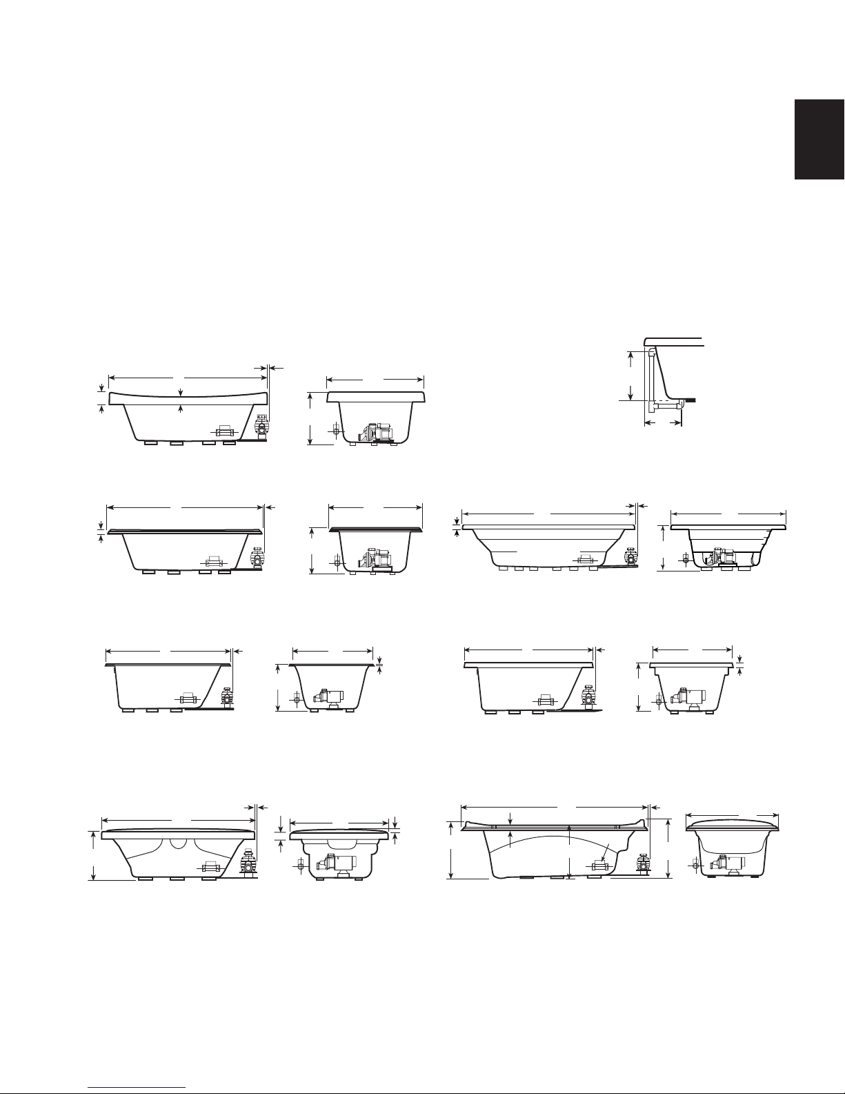
SPECIFICATIONS
)
Important: Read complete instructions before beginning installation.
Each whirlpool bath arrives ready for installation, completely equipped with motor/pump assembly , heater , plumbing, and fittings necessary for whirlpool operation. An optional drain/overflow kit is available for installation on the
bath.
Remove the bath from the carton. Retain the shipping carton until satisfactory inspection of the product has been
made. Do not lift the bath by the plumbing at any time; handle by the shell only.
Immediately upon receipt, inspect the shell before installing. Should inspection reveal any damage or defect in the
finish, do not install the bath. Damage or defect to the finish claimed after the bath is installed is excluded from the
warranty . Jacuzzi Whirlpool Bath's responsibility for shipping damage ceases upon delivery of the products in good
order to the carrier. Refer any claims for damage to the carrier . For definitions of warranty coverage and limit ations,
refer to the published warranty information packed with the product.
All bath units are factory tested for proper operation and watertight connections prior to shipping. NOTE: Prior to
installation, the bath must be filled with water and operated to check for leaks that may have resulted from
shipping damage or mishandling. Jacuzzi Whirlpool Bath is not responsible for any defect that could have been
discovered, repaired, or avoided by following this inspection and testing procedure.
4"
(102 mm)
L
(Heater)
2"
(51 mm)
SIDE VIEW
MAX 1"
W
H
(Motor)
END VIEW
A
B
DRAIN/OVERFLOW
ALLUSION
ENGLISH
2"
(51 mm)
H
L
SIDE VIEW
L
(Heater)
SIDE VIEW
L
(Heater)
SIDE VIEW
(Heater)
(Motor)
ELARA
MAX. 1/2"
MAX. 1/2"
(Motor)
BELLAVISTA
MAX. 1/2"
H
END VIEW
(51 mm)2"
(Motor)
SABELLA
H
W
W
END VIEW
W
END VIEW
1/2"
(13 mm
1"
(25 mm)
2"
(51 mm)
H1
L
(Heater)
(Motor)
MAX. 1/2"
H
END VIEW SIDE VIEW
CIPREA™, Right Hand
L
(Heater)
(Motor)
SIDE VIEW
MAX. 1/2"
H
W
END VIEW
REÁL™, Right Hand
L
(Heater)
2"
(51 mm)
SIDE VIEW END VIEW
H2
(Motor)
MAX. 1/2"
H3
TORRETTA 36
W
2"
(51 mm)
W
5
Jacuzzi Whirlpool Bath K339000X 3/06
Page 6

SPECIFICATIONS
SPECIFICATIONS (Rectangular) LH = Left Hand, RH = Right Hand
ENGLISH
MODEL
ALLUSION™
6636
RH
ALLUSION™
7236
RH
ALLUSION™
7242
RH
BELLAVISTA™
5
RH
BELLAVISTA™
5.5
RH
BELLAVISTA™
6
RH
CIPREA™
RH
ELARA™ 6042
LH & RH
ELARA™ 6636
LH & RH
ELARA™ 7242
LH & RH
REÁL™
RH
SABELLA™
RH
TORRETTA™ 36 72" (1829 mm) L
66" (1676 mm) L
36" ( 914 mm) W
26" ( 660 mm) H
72" (1829 mm) L
36" ( 914 mm) W
26" ( 660 mm) H
72" (1829 mm) L
42" (1067 mm) W
26" ( 660 mm) H
60" (1524 mm) L
42" (1067 mm) W
26" ( 660 mm) H
66" (1676 mm) L
42" (1067 mm) W
26" ( 660 mm) H
72" (1829 mm) L
42" (1067 mm) W
26" ( 660 mm) H
72" (1829 mm) L†
48" (1219 mm) W
20-1/2" ( 521 mm) H
60” (1524 mm) L
42” (1067 mm) W
23-1/2” (597 mm) H
66” (1676 mm) L
36” ( 914 mm) W
23-1/2” (597 mm) H
72" (1829 mm) L
42" (1067 mm) W
23-1/2" ( 597 mm) H
72" (1829 mm) L†
42" (1067 mm) W
23" ( 584 mm) H
72" (1829 mm) L
47" (1194 mm) W
23-3/4" ( 584 mm) H
35-1/8" ( 892 mm) W
22-7/8" ( 581 mm) H1
21" ( 533 mm) H2
23-1/2" ( 597 mm) H3
DRAIN/OVERFLOW
17-3/8" (441 mm) A
11-15/16" (210 mm) B
17-3/8" (441 mm) A
11-15/16" (210 mm) B
17-3/8" (441 mm) A
11-15/16" (210 mm) B
11-3/4" (298 mm) B
20" (508 mm) A
11-3/4" (298 mm) B
20" (508 mm) A
11-3/4" (298 mm) B
16-1/4" (413 mm) A
13-1/2" (343 mm) B
18.5” (470 mm) A
10.6” (269 mm) B
18.5” (470 mm) A
10.6” (269 mm) B
18.5” (470 mm) A
10.6” (269 mm) B
20" (508 mm) A
14" (356 mm) B
20" (508 mm) A
14" (356 mm) B
18-3/16" (459 mm) A
15" (381 mm) B
CUTOUT
Template
Provided
P/N
BY20000
Template
Provided
P/N
BY20000
Template
Provided
P/N
BY20000
Template
Provided
P/N
P187000
Provided
P/N
P187000
Provided
P/N
P187000
58" x 40"
(1473 mm x
1016 mm)
Umt Template
Provided
P/N DQ50000
64" x 34"
(1626 mm x
864 mm)
Umt Template
Provided
P/N DQ51000
70" x 40"
(1778 mm x
1016 mm)
Umt Template
Provided
P/N BZ51000
70" x 40"
(1778 mm x
1016 mm)
Template
Provided
P/N
P187000
Provided
P/N
P652000
TOTAL WEIGHT/
FLOOR LOADINGDIMENSIONS
843 lb
(383 kg)/
2
51 lb/ft
(248 kg/m2)
978 lb
(489 kg)/
2
54 lb/ft
(263 kg/m2)
1127 lb
(470 kg)/
2
54 lb/ft
(263 kg/m2)
1026 lb
(466 kg)/
2
59 lb/ft
(288 kg/m2)
1078 lb
(490 kg)/
2
56 lb/ft
(273 kg/m2)
1130 lb
(514 kg)/
2
54 lb/ft
(263 kg/m2)
895 lb
(407 kg)/
2
37 lb/ft
(180 kg/m2)
(512 kg)/
2
65.4 lb/ft
(319 kg/m2)
(472 kg)/
2
63 lb/ft
(307 kg/m2)
(611 kg)/
2
64 lb/ft
(312 kg/m2)
1130 lb
(514 kg)/
2
54 lb/ft
(263 kg/m2)
1199 lb
(545 kg)/
2
51 lb/ft
(249 kg/m2)
948 lb
(431 kg)/
2
54 lb/ft
(263 kg/m2)
OPERATING
GALLONAGE
Min - 55 U.S. gal
(208 liters)
Max - 75 U.S. gal
(284 liters)
Min - 65 U.S. gal
(246 liters)
Max-85 U.S. gal
(322 liters)
Min - 75 U.S. gal
(284 liters)
Max - 99 U.S. gal
(375 liters)
80 U.S. gal
(303 liters)
85 U.S. gal
(322 liters)
90 U.S. gal
(341 liters)
57 U.S. gal
(216 liters)
Min - 83 U.S. gal
(314 liters)
Max - 92 U.S. gal
(348 liters)
Min - 75 U.S. gal
(284 liters)
Max - 83 U.S. gal
(314 liters)
Min - 95 U.S. gal
(360 liters)
Max-105 U.S. gal
(398 liters)
90 U.S. gal
(341 liters)
98 U.S. gal
(371 liters)
70 U.S. gal
(265 liters)
PRODUCT
WEIGHT
135 lb
(61 kg)
145 lb
(66 kg)
169 lb
(77 kg)
110 lb
(50 kg)
120 lb
(56 kg)
130 lb
(59 kg)
170 lb
(77 kg)
200 lb
(91 kg)
200 lb
(91 kg)
215 lb
(98 kg)
130 lb
(59 kg)
133 lb
(60 kg)
115 lb
(52 kg)
SKIRT &
MOUNTING
Not Available
Not Available
Not Available
Not Available20" (508 mm) A
Not AvailableTemplate
Not AvailableTemplate
IncludedNA
Not Available1126 lb
Not Available1039 lb
Not Available1345 lb
Not Available
Not Available
Not AvailableTemplate
† Add 1/4" to this dimension when roughing-in for 3-wall niche.
NOTE: The overall dimensions are nominal with a tolerance of +0 and -1/4" (6,4 mm).
FOR ALL UNITS: Electrical Service Requirements: All require a dedicated GFCI protected separate circuit.
RapidHeatTM: 120 VAC, 15 AMP, 60 Hz. dedicated GFCI protected separate circuit.
Motor/Pump: 120 VAC, 20 AMP, 60 Hz. dedicated GFCI protected separate circuit.
HEATER,
INTAKE/DISCHARGE
Factory Installed
Intake
(S749000 Heater)
Factory Installed
Intake
(S749000 Heater)
Factory Installed
Intake
(S749000 Heater)
Factory Installed
Intake
(S749000 Heater)
Factory Installed
Intake
(S749000 Heater)
Factory Installed
Intake
(S749000 Heater)
Factory Installed
Intake
(S749000 Heater)
Factory Installed
Intake
(S749000 Heater)
Factory Installed
Intake
(S749000 Heater)
Factory Installed
Intake
(S749000 Heater)
Factory Installed
Intake
(S749000 Heater)
Factory Installed
Intake
(S749000 Heater)
Factory Installed
Intake
(S749000 Heater)
Jacuzzi Whirlpool Bath K339000X 3/06
6
Page 7
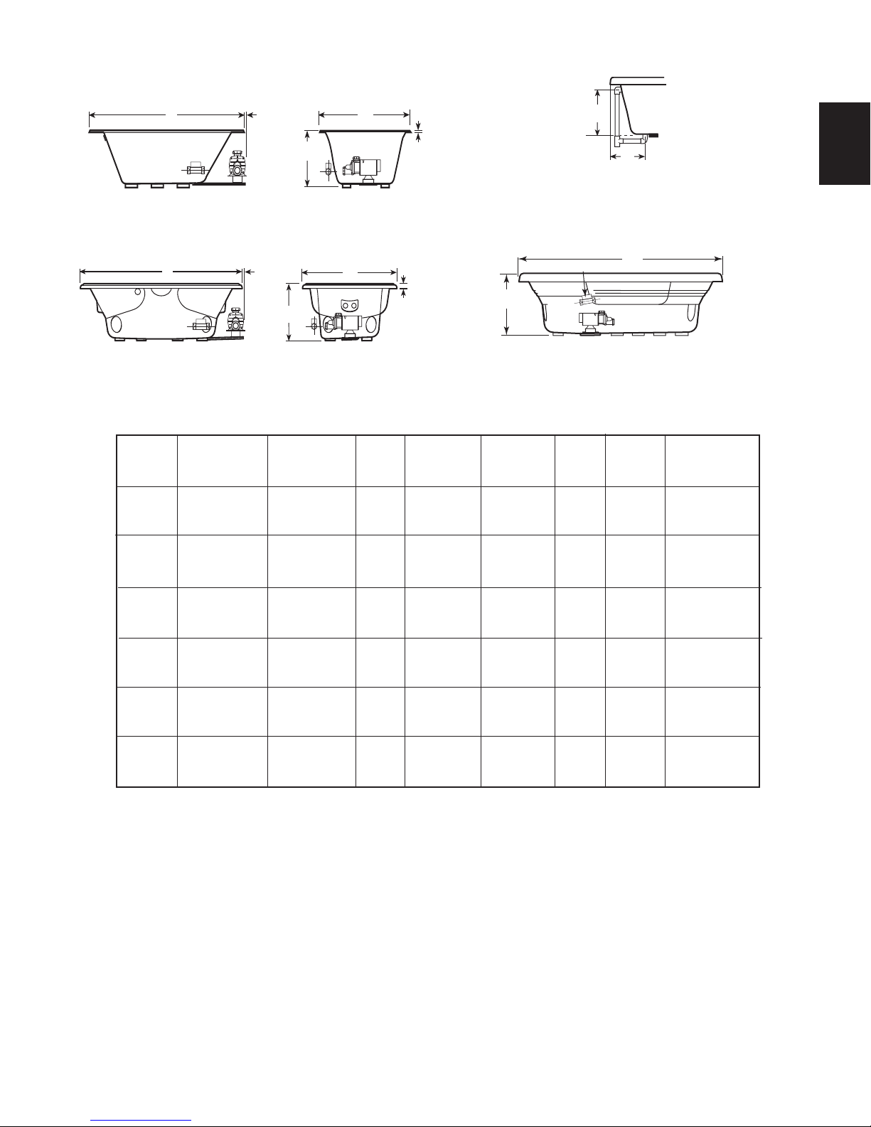
OVAL & ROUND BATHS
SPECIFICATIONS
L
(Heater)
MAX. 2-1/2"
H
W
1/2"
(13 mm)
(Motor)
SIDE VIEW
END VIEW
DUETTA™
(51 mm)
CUTOUT
70" Dia.
(1778 mm)
Hole
Template
Provided
P/N
DA09000
Template
Provided
P/N
DA08000
Template
Provided
P/N
DA07000
Template
Provided
P/N
DA06000
Template
Provided
P/N
P187000
2"
TOTAL WEIGHT/
FLOOR LOADINGDIMENSIONS
1293 lb
(588 kg)/
36 lb/ft
(176 kg/m2 )
999 lb
(454 kg)/
57.1 lb/ft
(278 kg/m2 )
1019 lb
(463 kg)/
61.8 lb/ft
(301 kg/m2 )
1106 lb
(503 kg)/
57.5 lb/ft
(280 kg/m2 )
1277 lb
(581 kg)/
60.8 lb/ft
(296 kg/m2 )
1130 lb
(514 kg)/
54 lb/ft
(263 kg/m2 )
GALLONAGE
2
2
Max - 83 U.S. gal
2
Max - 80 U.S. gal
2
Max - 95 U.S. gal
2
Max - 106 U.S. gal
2
OPERATING
100 U.S. gal
Min - 77 U.S. gal
Min - 75 U.S. gal
Min - 90 U.S. gal
Min - 98 U.S. gal
L
(Heater)
SIDE VIEW
(Motor)
MAX. 1/2"
H
W
END VIEW
VENICIA™
SPECIFICATIONS (Oval & Round) LH = Left Hand, RH = Right Hand
MODEL
CORTINA™
RH
DUETTA™
6042
RH
DUETTA™
6636
RH
DUETTA™
6642
RH
DUETTA™
7242
RH
VENICIA™
RH
72" (1829 mm) L
72" (1829 mm) W
22-1/4" ( 565 mm) H
60” (1524 mm) L
42” (1067 mm) W
26” ( 660 mm) H
66” (1676 mm) L
36” (914 mm) W
26” ( 660 mm) H
66” (1676 mm) L
42” (1067 mm) W
26” (660 mm) H
72" (1829 mm) L
42" (1067 mm) W
26" ( 660 mm) H
72" (1829 mm) L
42" (1067 mm) W
23" ( 584 mm) H
DRAIN/OVERFLOW
DIMENSIONS
16-3/4" (426 mm) A
19-1/4" (489 mm) B
18.4" (467 mm) A
11" (279 mm) B
18.4" (467 mm) A
11" (279 mm) B
18.4" (467 mm) A
11" (279 mm) B
18.4" (467 mm) A
11" (279 mm) B
20" (508 mm) A
14" (356 mm) B
W
(379 liters)
(291 liters)
(314 liters)
(284 liters)
(303 liters)
(341 liters)
(360 liters)
(371 liters)
(401 liters)
90 U.S. gal
(341 liters)
A
B
DRAIN/OVERFLOW
(Heater)
L
(Motor)
CORTINA™
PRODUCT
WEIGHT
210 lb
(95 kg)
110 lb
(50 kg)
180 lb
(82 kg)
117 lb
(53 kg)
130 lb
(59 kg)
130 lb
(59 kg)
SKIRT &
MOUNTING
Not Available
Not Available Factory Installed
Not Available Factory Installed
Not Available Factory Installed
Not Available Factory Installed
Not Available
HEATER,
INTAKE/DISCHARGE
Factory Installed
Discharge
(U394000 HEATER)
Intake
(S749000 Heater)
Intake
(S749000 Heater)
Intake
(S749000 Heater)
Intake
(S749000 Heater)
Factory Installed
Intake
(S749000 Heater)
ENGLISH
NOTE: The overall dimensions are nominal with a tolerance of +0 and -1/4" (6,4
mm).
FOR ALL UNITS: Electrical Service Requirements: All require a dedicated GFCI protected separate circuit.
RapidHeatTM: 120 VAC, 15 AMP, 60 Hz. dedicated GFCI protected separate circuit.
Motor/Pump: 120 VAC, 20 AMP, 60 Hz. dedicated GFCI protected separate circuit.
7
Jacuzzi Whirlpool Bath K339000X 3/06
Page 8

CORNER BATHS
SPECIFICATIONS
ENGLISH
H
SIDE VIEW
(Heater)
MAX. 1/2"
2"
(51 mm)
W
END VIEW
DRAIN/OVERFLOW
BELLAVISTA™ CORNER, Right Hand
SPECIFICATIONS (Corner) LH = Left Hand, RH = Right Hand
SKIRT &
MOUNTING
Not Available
P/N
TOTAL WEIGHT/
FLOOR LOADING
1046 lb
(475 kg)/
42 lb/ft
(205) kg/m
DRAIN/OVERFLOW
MODEL
BELLAVISTA
CORNER
RH
NOTE: The overall dimensions are nominal with a tolerance of +0 and -1/4" (6,4
FOR ALL UNITS: Electrical Service Requirements: All require a dedicated GFCI protected separate circuit.
mm).
RapidHeatTM: 120 VAC, 15 AMP, 60 Hz. dedicated GFCI protected separate circuit.
DIMENSIONS
TM
60" (1524 mm) L
60" (1524 mm) W
21-3/4" ( 553 mm) H
DIMENSIONS
18-7/8" (479 mm) A
14" (356 mm) B
CUTOUT
Template
Provided
P654000
2
2
OPERATING
GALLONAGE
80 U.S. gal
(303 liters)
PRODUCT
WEIGHT
130 lb
(59 kg)
Motor/Pump: 120 VAC, 20 AMP, 60 Hz. dedicated GFCI protected separate circuit.
A
B
HEATER,
INTAKE/DISCHARGE
Factory Installed
Intake
(S749000 Heater)
Jacuzzi Whirlpool Bath K339000X 3/06
8
Page 9
"
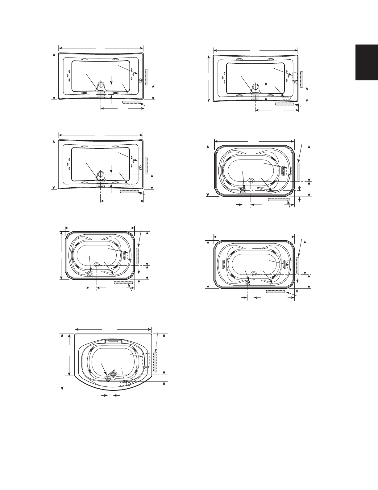
ROUGHING-IN REFERENCE
ROUGHING-IN REFERENCE (RECTANGULAR)
Some tubs are supplied with cutout and/or undermount template. Refer to CUTOUT on pages 6-8 for template part numbers.
66"
72"
ENGLISH
36"
42"
Motor
5" x 5"
ALLUSION™ 6636, Right Hand
72"
Motor
5" x 5"
ALLUSION™ 7242, Right Hand
66"
Motor
42"
4" x 4"
Heater
10"
BELLAVISTA™ 5.5, Right Hand
8-1/2"
Heater
8-1/2"
Heater
35-1/2"
33"
36"
12" H x 18" L
Service Access
6"
Opt. Service Access
12" H x 18" L
Service Access
11-15/16"
Opt. Service
Access
12" H x 18" L
Service Access
11-15/16"
Opt. Service
Access
30-1/8"
11-3/4"
36"
5" x 5"
ALLUSION™ 7236, Right Hand
42"
4" x 4"
7"
BELLAVISTA™ 5, Right Hand
42"
4" x 4"
10-1/2"
BELLAVISTA™ 6, Right Hand
60"
Motor
72"
Motor
8-1/2"
Heater
32-1/2"
Motor
Heater
35-13/16"
Heater
36"
Opt. Service Access
12" H x 18" L
Service Access
11-15/16"
Opt. Service
Access
12" H x 18" L
Service Access
30-1/8"
11-3/4
6"
12" H x 18" L
Service Access
30-1/8"
11-3/4"
6"
Opt. Service
Access
*72"
48"
36"
14" x 4"
Motor
Heater
4"
CIPREA™, Right Hand
* Add 1/4" to this dimension when roughing-in for 3-wall niche.
NOTE: 1. Measurements inside each unit represent cutout in floor to allow for drain/overflow.
2. All measurements are in inches. To convert to millimeters, multiply inches by 25.4.
3. Service access dimensions given are minimum size.
4. The overall dimensions are nominal with a tolerance of +0 and -1/4" (6,4 mm).
12" H x 18" L
Service Access
34-1/2"
7"
9
Jacuzzi Whirlpool Bath K339000X 3/06
Page 10

ROUGHING-IN REFERENCE
ELARA™ 6636 Right Hand
66"
36"
18 "
4.2"
10.6"
12" x 4"
Motor
Opt. Service
Access
12" H x 18" L
Service Access
Heater
2"
ROUGHING-IN REFERENCE (RECTANGULAR)
Some tubs are supplied with cutout and/or undermount template. Refer to CUTOUT on pages 6-8 for template part numbers.
60"
60"
ENGLISH
21"
4.2"
36"
12" H x 18" L
Service Access
12" x 4"
Motor
2"
Heater
10.6"
Opt. Service
Access
ELARA™ 6042 Left Hand
66"
Motor
Heater
Opt. Service
Access
12" x 4"
2"
10.6"
ELARA™ 6636 Right Hand
42"
12" H x 18" L
Service Access
4.2"
18 "
42"
12" H x 18" L
Service Access
12" x 4"
Motor
Heater
Opt. Service
Access
2"
10.6"
ELARA™ 6042 Right Hand
21"
4.2"
Opt. Service
Access
Heater
4.2"
10.6"
12" x 4"
Opt. Service
Access
Heater
12" H x 18" L
Service Access
42"
42"
Motor
72"
21"
2"
72"
Motor
12" H x 18" L
Service Access
ELARA™ 7242 Right Hand
ELARA™ 7242 Left Hand
* Add 1/4" to this dimension when roughing-in for 3-wall niche.
NOTE: 1. Measurements inside each unit represent cutout in floor to allow for drain/overflow.
2. All measurements are in inches. To convert to millimeters, multiply inches by 25.4.
3. Service access dimensions given are minimum size.
4. The overall dimensions are nominal with a tolerance of +0 and -1/4" (6,4 mm).
10.6"
12" x 4"
2"
4.2"
21"
Jacuzzi Whirlpool Bath K339000X 3/06
10
Page 11

ROUGHING-IN REFERENCE
ROUGHING-IN REFERENCE (RECTANGULAR)
Some tubs are supplied with cutout and/or undermount template. Refer to CUTOUT on pages 6-8 for template part numbers.
ENGLISH
42"
14"
5-1/4"
72"
18" x 4"*
3"
10-1/2"
Heater
REÁL™, Right Hand
Motor
36"
12" H x 18" L
Service Access
Opt. Service
Access
36"
47"
18"
1"
3"
18" x 4"
3"
10-1/4"
SABELLA™ Right Hand
6-3/4"
15-1/4"
TORRETTA™ 36, Left Hand
72"
3"
72"
15" X 4"
Motor
Heater
36"
1"
Motor
Heater
Opt. Service Access
12" H x 18" L
Service Access
7"
Opt. Service
Access
13-3/4"
12" H x 18" L
Service Access
* Add 1/4" to this dimension when roughing-in for 3-wall niche.
NOTE: 1. Measurements inside each unit represent cutout in floor to allow for drain/overflow.
2. All measurements are in inches. To convert to millimeters, multiply inches by 25.4.
3. Service access dimensions given are minimum size.
4. The overall dimensions are nominal with a tolerance of +0 and -1/4" (6,4 mm).
11
Jacuzzi Whirlpool Bath K339000X 3/06
Page 12

ROUGHING-IN REFERENCE
s
ROUGHING-IN REFERENCE (OVAL)
Some tubs are supplied with cutout and/or undermount template. Refer to CUTOUT on pages 6-8 for template part numbers.
60"
66"
ENGLISH
42"
13" x 4"
3.84"
30"
Motor
2"
11.04"
DUETTA™ 6042, Right Hand
66"
42"
13" x 4"
3.84"
33"
DUETTA™ 6642, Right Hand
Heater
2"
11.04"
Motor
Heater
Opt. Service
Access
Opt. Service
12" H x 18" L
Access
Service Access
12" H x 18" L
Service Access
36"
13" x 4"
3.84"
33"
2"
11.04"
Motor
Heater
Opt. Service Access
DUETTA™ 6636, Right Hand
72"
14" x 4"
Motor
Heater
3-1/2"
Opt. Service
36"
DUETTA™ 7242, Right Hand
2"
Access
12" H x 18" L
Service Access
42"
11"
12" H x 18" L
Service Access
12" H x 18" L
Service Acces
29-7/8"
12-1/8"
5-1/4"
42"
Opt. Service Access
10-1/2"
3"
72"
Motor
18" x 4"
Heater
36"
VENICIA™, Right Hand
NOTE: 1. Measurements inside each unit represent cutout in floor to allow for drain/overflow.
2. All measurements are in inches. To convert to millimeters, multiply inches by 25.4.
3. Service access dimensions given are minimum size.
4. The overall dimensions are nominal with a tolerance of +0 and -1/4" (6,4 mm).
Jacuzzi Whirlpool Bath K339000X 3/06
12
Page 13

ROUGHING-IN REFERENCE
ROUGHING-IN REFERENCE (ROUND, CORNER)
Some tubs are supplied with cutout and/or undermount template. Refer to CUTOUT on pages 6-8 for template part numbers.
60"
59-1/2"
Ref.
60"
34-9/16"
Motor
12"x4"
3"
BELLAVISTA™ CORNER, Right Hand
Heater
77-3/4"
7-1/2"
Service
Access
Opt.
Service
Access
16"
26"
16"
Motor
CORTINA™, Right Hand
9"
14"x5"*
5"
72"
Heater
12" H x 18" L
Service Access
4"
ENGLISH
72"
NOTE: 1. Measurements inside each unit represent cutout in floor to allow for drain/overflow.
2. All measurements are in inches. To convert to millimeters, multiply inches by 25.4.
3. Service access dimensions given are minimum size.
4. The overall dimensions are nominal with a tolerance of +0 and -1/4" (6,4 mm).
13
Jacuzzi Whirlpool Bath K339000X 3/06
Page 14

TYPICAL INSTALLATIONS
TYPICAL FLANGE MOUNTING DETAIL
INST ALLA TION INSTRUCTIONS
Framing and Support
The drain/overflow of the bath extends below the bottom of the bath. Note that this requires a cutout in the floor.
The floor structure beneath the bath must be able to support a total weight of bath, water, and bather.
Refer to the table under total weight for your model. The unit must be supported from the bottom of the bath and
not from the bath rim or tile flange. If the subfloor is level and a continuous surface, no other preparation is neces-
sary. You can proceed to install the bath. If the subfloor is not level, you MUST level the entire surface prior to
ENGLISH
installing the bath. The use of materials that provide a level installation are allowed provided the method used will
insure a level bath that is supported from the bottom. Materials that may be used are a floor leveling compound,
mortar , plaster or minimal expansion structural foam having a density of a minimum of 5 lbs./cubic feet; however the
bath must remain level in order for it to drain properly and all foam feet must make full contact with the leveling
material. Both sides of a joint or splice of subfloor should be level to each other. When attaching baths with
flanges to stud wall, use shims to fill any gaps between the bath flange and studs.
NOTE: Drop-in tubs are additionally equipped with metal anchor straps. With a level floor, when mortar or
similar anchoring material is NOT used, use construction adhesive under the foam feet and fasten the metal
anchor straps to the floor to prevent the unit from shifting while trim, deck finishes, or finish caulking cure.
The rim of the bath is not designed to support weight. If finish material is to overlap or contact the bath, the added
weight must be fully self-supporting.
The protective film liner inside the bath is used to prevent damage to the finish during installation. Before
installation, remove liner to inspect for any defects, reapply and do not remove until final cleanup.
Important: If a skirt is to be used, it must be installed at the time of unit installation – refer to skirt installation instructions. Install optional trim parts when all installation has been completed.
MORTAR OR ADHESIVE
FLASHING
1" X 4" (NOT FOR SUPPORT)
FLUSH TO WALL
STUD
CAULKING
FLANGE
SHIM IF
NECESSARY
TO FILL GAPS
BETWEEN
STUD
AND FLANGE
1/8" GAP
TILE
SEALANT
MORTAR OR ADHESIVE
SEALANT
SUB-FLOOR
FLASHING
1" X 4" (NOT FOR SUPPORT)
SEMI-SUNKEN
TILE
CEMENT
BOARD
TILE
ADHESIVE
ATTACH WITH
SCREWS
PROVIDED
SHIM IF
STUD
FLANGE
NECESSARY
TO FILL GAPS
BETWEEN
STUD
AND FLANGE
TILE
STUD
FLANGE
1/8" GAP
FINISHING
MATERIAL
PLASTER
FILLER
FLANGE
NAIL
OR
SCREW
STUD
WALL
MORTAR
CEMENT
BOARD
BATH RIM
SILICONE
SEALANT
1" X 4" (NOT FOR
SUPPORT)
OPTIONAL TILE FLANGE KIT
CAULKING
ATTACH WITH
SCREWS
PROVIDED
1"X 4"
(NOT FOR
SUPPORT)
TILE
CEMENT
BOARD
TILE
ADHESIVE
STUD
FLANGE
Jacuzzi Whirlpool Bath K339000X 3/06
14
Page 15

INST ALLA TION INSTRUCTIONS
SERVICE ACCESS
SERVICE ACCESS
Service Access
For partially or fully sunken installations, allow for access to service connections. It is the installer's responsibility to provide sufficient service access. The recommended minimum dimensions allowable for service to
the bath are shown in the "Service Access" illustration.
Provide adequate area around unit for air circulation
for cooling the motor and to supply sufficient air to the
jets. Do not insulate this area or around motor.
(WITHOUT SKIRT)
12"
ALTERNATE
ACCESS
12"
18"
MOTOR
18"
PREFERRED
ACCESS
The Duetta Whirlpool baths should access as shown
below.
DUETTA SERVICE ACCESS (WITHOUT SKIRT)
HEATER
FRONT
PREFERRED
ACCESS
12"
18"
MOTOR
18"
ALTERNATE
ACCESS
The Allusion Whirlpool baths should access as shown
below.
ALLUSION SERVICE ACCESS
PUMP/MOTOR
FRONT
ALTERNATE
ACCESS
HEATER
12"
18"
12"
18"
PREFERRED
ACCESS
ENGLISH
12"
Service Access (Corner Tubs)
For partially or fully sunken installations, allow for access to service connections. It is the installer's responsibility to provide sufficient service access. The recommended minimum dimensions allowable for service to
the bath are shown in the "Service Access" illustration.
Provide adequate area around unit for air circulation
for cooling the motor and to supply sufficient air to the
jets. Do not insulate this area or around motor.
SERVICE ACCESS
18"
RIGHT HAND UNIT SHOWN
A - Preferred access
B - Acceptable alternative if access A is not possible
C - Additional access for equipment (Optional)
(CORNER BATHS)
C
36"
In some cases, access may not have been provided
because of the design of the bath environment and having full understanding that in this case, it may be necessary to remove the unit for service.
If this is the case, diagnosing a problem may not be
possible without complete access to the plumbing system. This would necessitate the removal of the unit.
Although this practice is not commonly implemented, it
is an acceptable method.
MOTOR
AREA
A
20"
A
B
In some cases access may have been provided in
AREA
B
Area A but service is required in Area B which requires
24"
the unit to be pulled for service and reinstalled.
If service access has not been provided, it is the
home owners responsibility to remove the bath and
provide the required access, should a repair become
necessary.
15
Jacuzzi Whirlpool Bath K339000X 3/06
Page 16

INSTALLATION INSTRUCTIONS
INSTALLATION CLEARANCE RECOMMENDATIONS
The installation clearance recommendations below are to ensure that installers have enough space to maneuver and
insert tub. The Designer/Luxury line whirlpool tubs have electrical, plumbing and lighting systems installed. Do not
lift the bath by the plumbing or wiring at any time; handle by the shell only.
ENGLISH
32"
32"
TUB
CUTOUT
TUB
CUTOUT
TWO WALL INSTALLATION
3"
THREE WALL INSTALLATION
3"
32"
TUB
CUTOUT
10"
TUB
CUTOUT
10"
32"
48"
MINIMUM VERTICAL CLEARANCE
FOR INSTALLER TO POSITION TUB
32"
3"
Jacuzzi Whirlpool Bath K339000X 3/06
16
Page 17

INSTALLATION INSTRUCTIONS
Installation
Note that the motor/pump protrudes beyond the bath rim a maxi-
mum distance of 1" (25,4 mm). Care should be used when lowering
See END/SIDE VIEW in
Specification pages for
this dimension.
the tub into cutout to prevent injury to installer(s), finished surfaces,
or tub and components.
Clearance must be provided for installers. See page 16 for
(Heater)
(Motor)
recommended clearances surrounding tub. Damage to shell,
plumbing, wiring, lighting, and other components because of
failure to observe minimum clearances are not the responsibility
of Jacuzzi Whirlpool Bath.
All deck finish work must be completed before installation. Use the Cutout Template provided. Flooring surface inside
the cutout to deck height must not exceed height specification for tub.
Cover all finished surfaces to protect from damage during tub installation.
Turn OFF power supply to dedicated GFCI protected circuits.
Begin Installation
Optionally, use a washable marker to scribe a reference line 1" (25,4 mm) outside the cutout edge on the deck surface. This may assist in final alignment of the
tub.
Install any trim kits, faucets, or other tub components before installing.
To install unit insert the motor/pump end first when lowering the tub into the
cutout opening as shown in the bottom illustration. Do not use plumbing fixtures or
plumbing lines to lower unit. The clearance under the substrate is required for air
flow circulation requirements.
Place a piece of scrap lumber under each corner as a temporary support for the tub rim. Inspect all fittings, plumbing, and
control lines after inserting to insure components are not damaged, disconnected, or contacting the finish surface substrate or
support members.
Connect flex water supply lines to faucet.
Plug power cords into GFCI outlet.
Remove fingers, hands, and all other items from under the rim edge before lowering the tub.
Slightly lift one tub end and remove the scrap lumber . Gently lower the tub rim until it contacts the
deck surface. Slightly lift the remaining tub end and remove the scrap lumber. Gently lower the
tub rim until it contacts the deck surface.
If you created the optional reference lines, align the tub over the cutout.
Connect drain line.
Turn ON the power supply to the dedicated GFCI protected circuits.
Check for leaks and check system operation.
TUB
CUTOUT
REFERENCE
LINE
APPROX. 2-1/2"
SUBFLOOR
2 " MAX
THICKNESS
SUPPORT
1/2"
FINISHED SURFACE
SCRAP LUMBER
SUBSTRATE
ENGLISH
TILE OR
FINISHED
SURFACE
SUBSTRATE
SUPPORT
MEMBER
17
SUBFLOOR
** MIN CLEARANCE - DUETTA 3"-3½"
TILE OR FINISHED
SURFACE
SUBSTRATE
TYP MIN. 1-1/2"
CLEARANCE**
SUPPORT
MEMBER
Jacuzzi Whirlpool Bath K339000X 3/06
Page 18

INST ALLA TION INSTRUCTIONS
Electrical Connections
Separate circuits, each must be protected by a Ground Fault Circuit Interrupter (GFCI), are required for the pump/
motor and the RapidHeatTM Heater. Refer to the electrical specification for each model on p ages 6-8. Install duplex
outlets to the studwall underneath the bathtub, at least 4 inches (10,2 cm) above the floor or in accordance with local
building or electrical codes. Duplex outlets are not provided. Because these units are manufactured with an electronic control panel no remote switch or timer is necessary .
ENGLISH
Tubs with electronic control panels combine the electrical requirements of the pump/motor and electronic controls
into a control box. For these units the power supply cord from the pump/motor runs to the control box. The power
supply cord from the control box should be connected to the 20 AMP GFCI circuit.
Before installing electrical connections, inspect the pump/motor and heater nameplates and confirm you have 120
V AC, 20 AMP and 15 AMP service requirements. The GFCI circuit s must match these requirements. Care must be
taken to connect the 20 AMP pump/motor or control box power cord ONL Y to the 20 AMP GFCI circuit and to connect
the 15 AMP heater power cord ONLY to the 15 AMP GFCI circuit. Do NOT switch power cords and GFCI circuit s.
With a #8 solid copper wire, bond the heater to the house electrical panel or approved local bond. A bonding lug is
provided on the heater. With another #8 solid copper wire, bond the pump/motor to the house electrical panel or
approved local bond. A bonding lug is provided on the pump/motor.
At initial start-up and before each use thereafter with power ON, push the GFCI test button on each circuit. The
reset button should pop out. Push this button in to reset. If the interrupter fails to operate in this manner, there is a
ground current flowing or a device malfunction, indicating the possibility of electrical shock. Turn off power and do
not use the bath until the source of the problem has been identified and corrected.
DANGER: RISK OF ELECTRIC SHOCK. Connect only to a circuit protected by a Ground Fault Circuit Interrupter (GFCI).
CAUTION: Operating the motor/pump without enough water in the bath can cause leaking and permanent
damage to the pump. Before power is applied to the installation, make sure the switch is in the OFF position
to avoid pump damage.
ELECTRICAL CONNECTION
15 AMP, 3 PRONG PLUG
(Heater)
20 AMP, 3 PRONG PLUG
(Pump/Motor)
M
T
HEATER
* INSTALL SEPERATE
GFCI PROTECTED CIRCUITS,
DUPLEX RECEPTS NOT PROVIDED
DUPLEX
RECEPT.*
4" MIN.
OR IN
ACCORDANCE
WITH LOCAL
BUILDING OR
ELECTRICAL
CODES
Jacuzzi Whirlpool Bath K339000X 3/06
18
Page 19
Plumbing and Water Supply
Drain Information
A drain/overflow assembly (sold separately) must be installed on the bath, water tested, and connected to the sanitary system of the house. After opening the carton, inspect
for damage and verify that the kit is of the proper finish. In the
Jacuzzi Whirlpool Bath drain/overflow kit, note that the waste
flange, strainer, overflow cover and cover screws are packaged in a separate package within the kit to protect the trim
finish. Follow the installation instructions provided with the
drain/overflow kit. After the drain is fully installed, test for
proper drainage. If the unit does not drain properly, rectify
this condition before proceeding with the installation. Jacuzzi
Whirlpool Bath is not responsible for removal and or reinstallation costs.
NOTE: Watertight installation of the drain is the inst aller's
responsibility. Drain leakage is excluded from the Jacuzzi
Whirlpool Bath warranty of this product.
Plumbing
Pump, jets, and suction fittings for the whirlpool system
are factory plumbed in schedule 40 PVC piping.
All Jacuzzi Whirlpool Bath products are factory tested for
proper operation and watertight connections prior to shipping.
If leaks are detected, notify your Jacuzzi Whirlpool Bath dealer.
Do not install the unit.
Water Supply
Consult local authorities for plumbing code requirements
in your area.
IMPORTANT: Proper installation of the fill spout plumbing and compliance with local codes are the responsibility of the installer . Jacuzzi Whirlpool Bath does not warrant connections of water supply fittings and piping, fill
systems, or drain/overflow systems. Nor is it responsible
for damage to the bath which occurs during installation.
CAUTION: A nonflammable protective barrier must be
placed between soldering work and bath unit to prevent
damage to the bath.
Shower Information
Because of some baths' unique contour design, a rigid
shower door cannot readily be installed. If a shower is desired, we recommend a hand-held shower be installed in conjunction with a shower curtain, as this will allow the user to
control the direction of the spray.
NOTE: Proper installation of a shower is the responsibility of the installer . Jacuzzi Whirlpool Bath is not responsible for damage to the unit or for water damage which
might occur due to its installation.
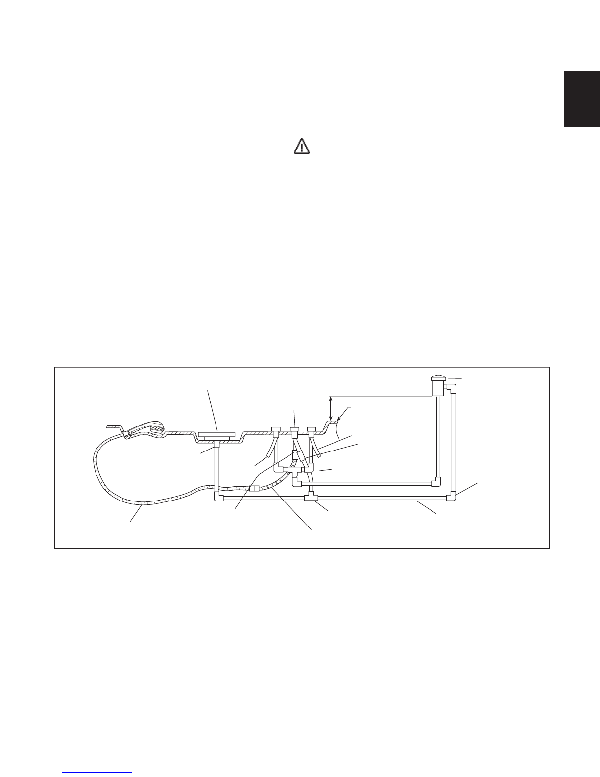
Anti-Siphon Valve
Optional Anti-Siphon valve installation. Anti-Siphon valve
is not supplied with the tub. Consult your local plumbing code
requirements for the minimum height above the tub rim.
ENGLISH
RECOMMENDED WATER SUPPLY CONNECTIONS
WATER RAINBOW® FILLSPOUT
3/4" FPT x 5/8" O.D.
COMPRESSION
SHOWER HOSE 1/2" FPT
COLD
WATER
SUPPLY
1/2" FPT x 3/8" NOM.
ADAPTER
(NOT ALL REQUIRE OR HAVE ALL FEATURES SHOWN)
DIVERTER HANDLE
1/2" MPT x 1/2" MPT x 18" FLEXIBLE
6"
BATH RIM
HOT WATER SUPPLY
3/8" FPT x 1/2"
NOM. COUPLING
3/8"x1/2"
NOM. ELL (2)
1/2" NOM. TEE
ANTI-SIPHON VALVE
THESE ITEMS SHOWN
FOR EXAMPLE ONLY
Consult local authorities
for plumbing code
requirements in your area.
1/2" NOM.
ELL (TYP)
1/2" NOM. COPPER (TYP.)
Clean-Up After Installation
To avoid dulling and scratching the surface of the bath, never use abrasive cleaners. A mild liquid detergent and warm water
will clean soiled surfaces.
Remove spilled plaster with a wood or plastic edge. Metal tools will scratch the surface. Spot s lef t by plaster or grout can be
removed if lightly rubbed with detergent on a damp cloth or sponge.
Paint, tar , or other difficult surface st ains can be removed with paint thinner, turpentine, or isopropyl alcohol (rubbing alcohol).
NOTE: Use these chemicals only on SURFACE stains.
Minor scratches which do not penetrate the color finish can be removed by lightly sanding with 600-grit wet/dry sandpaper.
You can restore the glossy finish to the acrylic surface of the bath with a special compound, Meguiar's #10 Mirror Glaze. If that
is not available, use automotive rubbing compound followed by an application of automotive paste wax.
Major scratches and gouges which penetrate the acrylic surface will require refinishing. Ask your Jacuzzi Whirlpool Bath
dealer for special instructions or visit our web site at http://www.jacuzzi.com/. To find service agent listings for:
Electrical or Mechanical Repairs visit http://jacuzzi.com/pdf/ASA.PDF
Finish, Surface, or Shell-Related Repairs visit http://jacuzzi.com/pdf/AFC.PDF
Repair Parts or Accessories visit http://jacuzzi.com/pdf/MPD.PDF
19
Jacuzzi Whirlpool Bath K339000X 3/06
Page 20

T
OPERATING INSTRUCTIONS
DIRECTIONALLY
ADJUSTABLE
FULLY
ADJUSTABLE
JETS
OPERATION
NOTE: These instructions pertain to all bath products manufactured by Jacuzzi Whirlpool Bath. Not all features discussed in this instruction pamphlet apply to all baths.
All baths manufactured by Jacuzzi Whirlpool Bath are designed for "fill and drain," which means the bath should be drained
after each use and filled with fresh water by the next bather. This is a health precaution, as these baths are not designed to hold
water continuously like pools or spas. If you want a unit designed to continuously hold water, see your Jacuzzi Whirlpool Bath
dealer for the complete line of whirlpool spas available.
ENGLISH
Once the bath is installed, remove any residue or foreign materials left over from construction. Paint, tar , or other difficult surface
stains can be removed with paint thinner, turpentine, or isopropyl alcohol (rubbing alcohol). NOTE: Use these chemicals only on
SURFACE stains. Other dirt can be cleaned off with a mild liquid detergent on a damp cloth. Scrape off plaster with a wooden or
plastic edge; do not use metal scrapers, wire brushes or other metal tools, as they will damage the bath's surface.
Water Level
Close the drain and fill the bath until water is at least 1" to
2" (2,5 - 5,08 cm) above the highest jet (see water line indicated in the illustration). Do not turn on the whirlpool sys-
tem at any time if the jets are not completely immersed in
water. Do not immerse the control panel by overfilling
the bath. Running the whirlpool system when there is insuf-
ficient water in the bath could result in water spraying outside
the bath area. Running the whirlpool system without water
will damage the recirculating pump.
IMPORTANT: When exiting the bath, the water level will drop
below the jets which could result in water being sprayed out
of the unit. To prevent this, you must turn unit off before
exiting bath.
FILL TO AT LEAST
1" - 2" ABOVE HIGHEST JET
1" - 2"
Controlling Whirlpool Action
The whirlpool action in your bath, controlled manually and
electronically, is influenced by three factors – direction of flow ,
force of water, and force of air. Every bath manufactured by
Jacuzzi Whirlpool Bath that is equipped with fully adjustable
PowerPro® jets, are manually adjustable for direction and water
force. Some baths have additional jets which can be adjusted
for direction only. Baths equipped with 2 speed motors and
electronic controls can also influence water force and force
of air.
Direction: T o change the direction of the water flow , swivel
the jet nozzle to the desired angle. The jets can be directed
individually toward any location on your body to provide a
hydromassage. The jets can also be adjusted so that they all
point in the same direction (clockwise or counterclockwise)
to circulate the water in a circular motion around the bath,
causing a total whirlpool effect.
Water Force: The high volume, fully adjustable PowerPro
jets can be manually adjusted to control the force of the water
coming into the bath. For robust action, increase the force of
the flow by rotating the jet handles to the left (counterclockwise). For a more gentle effect, rotate the handles to the right
(clockwise). Customize water force by lowering water volume
of one (1) jet(s) to increase water force in another jet(s). In
units with 2 speed motors the water force can be increased or
decreased using the electronic control. Never run the whirl-
pool system with all the jets closed.
Force of Air: Force of air is controlled electronically. Re-
fer to the Control panel instructions for details in adjusting
force of air.
Jacuzzi Whirlpool Bath K339000X 3/06
YPICAL BATH FITTINGS
ELECTRONIC CONTROL PANEL
FULLY ADJUSTABLE JETS
SUCTION
COVER
WATER RAINBOW
FILL SPOUT (OPTIONAL)
®
DRAIN/OVERFLOW
(OPTIONAL)
20
Page 21

OPERATING INSTRUCTIONS (cont'd)
Electronic Control Panel Operation (with optional Chromotherapy/Illumatherapy
All tubs in this product line come with electronic controls and standard Chromotherapy or IllumatherapyTM. Read and follow the
operation instructions for the control system of your unit.
General Functions
This Jacuzzi tub is equipped with a seven button electronic control panel. The seven button panel controls a two speed pump/
motor, Chromotherapy or IllumatherapyTM lighting, air controls, and wave control. LED lights (in the control panel) indicate function
levels. When switching between functions, the LED for the inactive functions will dim and the active function will brighten.
The bath is equipped with a water level sensor(s). When the water level is below the sensor, the pump/motor can not be
activated. If the ON/OFF pump/motor button is pressed at this time, the pump/motor will not operate. When the water goes
above the water level sensor, the pump/motor can be activated. If the water level drops below the level sensor, the pump/motor
will shut OFF. To restart the pump/motor after the water level goes above the level sensor, the ON/OFF pump/motor button must
be pressed. The pump/motor will automatically shut off 30 minutes after the pump/motor was turned on.
NOTE: Ensure the water level sensor located inside the bath is free of any soap or dirt buildup.
Normal Operation (with the bath filled to the proper level)
Pump/Motor Switch (ON/OFF )
Pressing the button will turn ON the two speed pump/
motor at HIGH speed. Pressing a second time will turn OFF
the pump/motor. To change speeds use the Toggle buttons.
Pump/Motor Status LED
Left Air Valve
Status LED
Pump/Motor
Status LED
Left Air Valve
TM
lighting)
Bath Light
Right Air Valve
Right Air Valve
Status LED
ENGLISH
When the pump/motor is ON at HIGH speed all four LED
indicator lights will be lit. When the pump/motor is ON at
LOW speed the bottom LED indicator light will be lit.
Left Air Valve Switch
Pressing this button will acitvate the left air valves use
the Toggle buttons to increase/decrease air flow to the left set
of jets. The air flow can be adjusted from no air to maximum
air.
Left Air Valve Status LED
The Left Air Valve Status LED will show four LED lights at
maximum air and only one LED light when the air is turned
OFF. Each additional LED indicates more air flow.
Right Air Valve Switch
Pressing this button will acitvate the right air valves. Use
the Toggle buttons to increase/decrease air flow to the right
set of jets. The air flow can be adjusted from no air to maximum air.
Right Air Valve Status LED
The Right Air Valve Status LED will show four LED lights at
maximum air and only one LED light when the air is turned
OFF. Each additional LED indicates more air flow.
Bath Light Switch (ON/OFF )
Pressing this button will turn ON the white bath light(s).
Pressing the Toggle buttons at this time will increase or decrease light intensity. Pressing the button a second time will
access the saved favorite color. To cycle lighting colors use
the Toggle button. Pressing the Toggle button again will stop
the light cycling. The color displayed when the cycle has been
stopped will be saved as your favorite color. Pressing the
button a third time to turn OFF the light.
NOTE: When switching between functions, the LED for
the inactive functions will dim and the active function will
brighten.
ON/OFF
Pump/Motor
Wave Function
Toggle Buttons
Wave Function Switch (ON/OFF )
Pressing this button activates wave action by opening
and closing both right and left air valves. Pressing a second
time will turn OFF the wave action.
T oggle Buttons
The T oggle buttons, up and down , act on each of the
other buttons to increase, decrease, or modify functionality.
Use the up arrow to increase and the down arrow to decrease.
• Pressing a toggle button after pressing the Pump/Motor
button will increase or decrease speeds on the Pump/Motor. If the pump/motor is on HIGH speed press the down
arrow to select LOW speed. If the pump/motor is on LOW
speed press the up arrow to select HIGH speed.
• Pressing an up or down toggle button after pressing the
Bath Light button once will increase or decrease the white
light brightness. Pressing an up or down toggle button
after pressing the Bath Light button twice will begin cycling
the light colors. Leave the colors cycling or press the same
toggle button again to stop the color cycling. With the lights
stopped on a color pressing the Bath Light button a third
time will turn OFF the light. (A favorite color will be saved
ONLY when the cycling has been stopped on that color
and then turned OFF.)
21
Jacuzzi Whirlpool Bath K339000X 3/06
Page 22

PUSH TO RESET
OVER HEAT
PROTECTION
HIGH LIMIT RESET
HEATER ON
HEATER ON
OPERATING INSTRUCTIONS (cont'd)
RapidHeat
TM
These units have a RapidHeatTM heater installed on the intake or discharge lines. The
heater will help maintain the temperature of the water in the bath.
Operation
ENGLISH
With the heater installed and the whirlpool pump is operating, the heating function is totally automatic. No user control required.
Vacuum/Pressure Switch
The heater is equipped with a preset vacuum/pressure switch which will not allow the heater to turn ON if the pump is not running with water flowing through the whirlpool system.
High-Limit Switch
The heater includes an exclusive High-Limit switch. This safety circuit will not false trip from hot tap water. It will only turn of f
the heater if the thermostat fails. To reset, press the button. If the high-limit trips frequently, contact your Authorized Electrical/
Mechanical Service Provider. Visit our web site at http://www.jacuzzi.com/.
To find service agent listings for:
Electrical or Mechanical Repairs visit http://jacuzzi.com/pdf/ASA.PDF
Finish, Surface, or Shell-Related Repairs visit http://jacuzzi.com/pdf/AFC.PDF
Repair Parts or Accessories visit http://jacuzzi.com/pdf/MPD.PDF
22
Jacuzzi Whirlpool Bath K339000X 3/06
Page 23
E
MAINTENANCE INSTRUCTIONS
Cleaning the Bath
To clean your bath, simply use a mild, nonabrasive liquid
detergent solution. Y ou can protect and restore the gloss to a
dulled acrylic surface by applying Meguiar's #10 Mirror Glaze,
a product specifically designed for use on acrylic finishes. If
Meguiar's is not available, an acrylic polish of equal quality or
automotive paste wax is acceptable.
Never use abrasive household cleaners on any Jacuzzi
Whirlpool Bath product.
Repairs to the Surface
Minor scratches which do not penetrate the color finish
can be removed by lightly sanding with 600-grit wet/dry sandpaper . Restore the gloss using Meguiar's Mirror Glaze or automotive paste wax.
Major scratches and gouges which penetrate the acrylic
surface will require refinishing. Ask your Jacuzzi Whirlpool
Bath dealer for special instructions.
Bath Additives
NOTE: DO NOT USE OIL OR OIL BASED BATH ADDITIVES.
If you want to use any kind of bath additive, use only a small
amount of low-foaming powder or crystal substance; the
whirlpool action intensifies the foaming properties of soaps.
The use of certain bath oils, bubble baths and bath additives may increase the level of accumulations of bath residue
in the whirlpool system. If excess accumulations persist, you
should discontinue use of these products.
Purging the Whirlpool System
NOTE: THE WHIRLPOOL SYSTEM SHOULD BE PURGED
AT LEAST TWICE A MONTH
To remove accumulations of bath residue from the whirlpool system, it is recommended that a whirlpool bath be
purged at least twice a month. For best results, however, we
recommend that you purge your whirlpool bath after each use
using, Systems Clean™, our exclusive two-part plumbing
system cleaner made specifically for whirlpool baths.
Systems Clean™ is available through an authorized Jacuzzi
Whirlpool Bath distributor or by calling us direct at 1-800-288-
4002.
Systems Clean™
Refer to the instructions on the Systems Clean™ packet.
CAUTION: DO NOT USE WHILE BATHING! USE EXTREME
CAUTION WHEN HANDLING THIS PRODUCT!
Immediately after bathing and exiting the whirlpool bath,
leave the bath water in the tub and add more hot water. The
water level in the tub must be at least 2” (5,08 cm)above the
highest jet. NOTE: Inducted air from the hydromassage
system will cause the Systems Clean™ contents to foam
increasing odor. Turn OFF the whirlpool air control or turn it to
the lowest setting and pour in the entire contents of PACKET
#1 ONLY directly into the bath water. For best results, pour the
System Clean into the tub near the intake for the circulation
pump and be sure to avoid contact with your skin. Allow the
whirlpool to run for 30 seconds and then add PACKET #2
ONLY. It is important to use PACKET #1 before PACKET
#2 to avoid a strong odor. Allow the bath to run for 5 to 10
minutes then drain the tub completely. Refill the tub with cold
water and run for 2 to 3 minutes. Drain completely and rinse
off any residue. Remember to reset the air valves to your
bathing comfort level.
Instructions for use:
ENGLISH
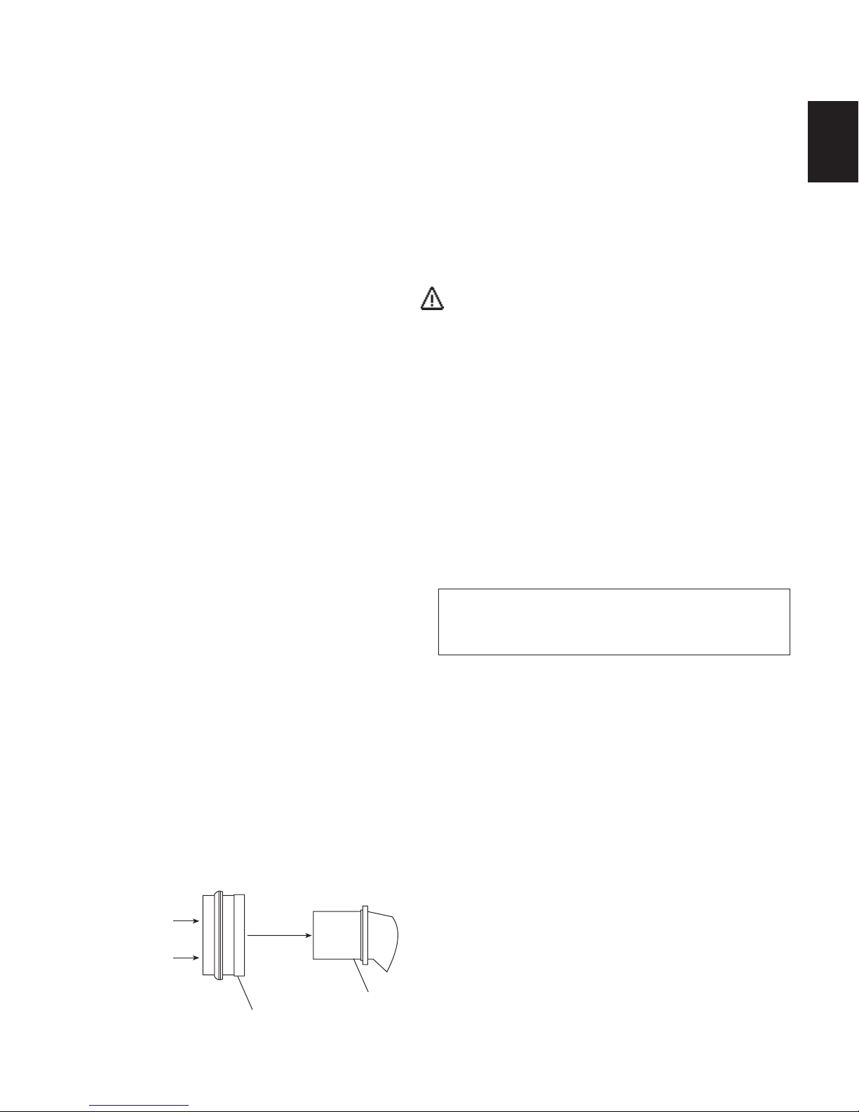
Spinning Jets Maintenance
(Models equipped with spinning jets)
If hair or other kind of debris gets caught in the bearings of
these jets, it could cause them to stop spinning. This may
require disassembly and cleaning. To do this, simply grab the
nozzle and pull straight out of the jet housing. The bearing
casing will be attached to the nozzle. These can be separated
by holding the casing and pushing the nozzle out from the rear
of the casing. After cleaning, reassemble in reverse.
PUSH FROM REAR
TO REMOVE
NOZZLE
NOZZL
BEARING CASING
DANGER: Harmful if swallowed. Eye irritant. Protect your
eyes, skin and mucus membranes from contact with this
product or its concentrated solution. A strong alkaline
product can cause severe burns to the eyes and skin.
If you have followed the standard purging instructions
above and still have an excess accumulation of bath residue
and desire an alternative cleaning mechanism, we recommend SUPER SYSTEMS CLEAN™ PLUS manufactured by
Stearns Packaging to rectify this condition. This may be
obtained by contacting us at 1-800-288-4002. It is recommended that you follow the instructions provided by the
manufacturer with the product. Repeated use may be necessary. SUPER SYSTEMS CLEAN™ PLUS does not replace
the necessity to regularly purge your whirlpool system with
Systems Clean™ as recommended.
23
Jacuzzi Whirlpool Bath K339000X 3/06
Page 24
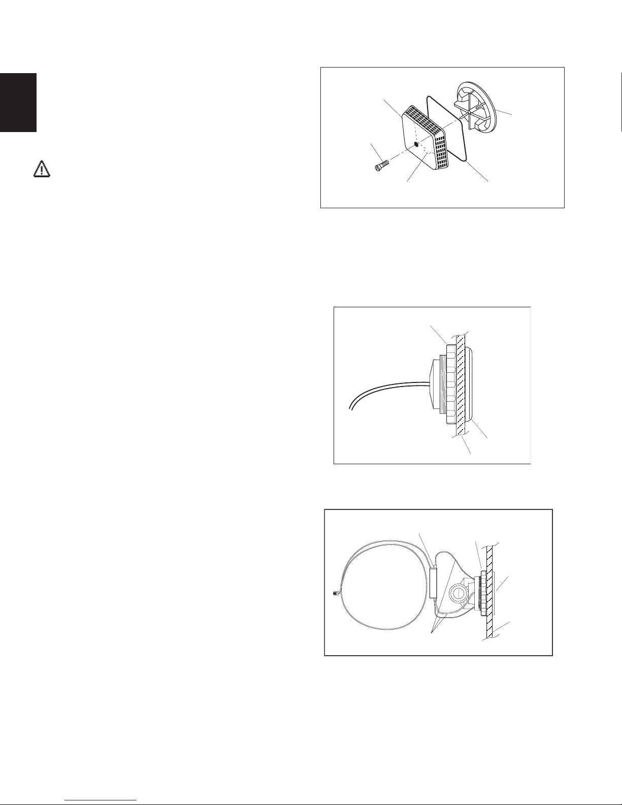
NOTCH
GASKET
COVER STRAINER
SCREW
SUCTION
FITTING
SUCTION COVER/STRAINER ASSEMBLY
MAINTENANCE INSTRUCTIONS
Suction/Intake Cover/Strainer Maintenance
Clean the suction/intake cover/strainer of hair and debris
when necessary. To do this, remove the center screw and
detach the square cover. Clean the cover by backflushing
debris from the holes. Replace the suction/intake cover im-
ENGLISH
mediately after cleaning. When reinstalling, orient the cover/
strainer with the small notch at the bottom. The gasket must
be inserted into the groove of the cover/strainer before reinstalling onto the suction fitting.
CAUTION: Keep hair a minimum of 6 inches (15,2 cm)
away from the suction/intake fitting at all times when the
whirlpool system is operating. Hair longer than shoulder
length should be secured close to the head, or a bathing
cap should be worn. Do not operate the whirlpool system with the suction/intake cover removed! It is a safety
device and must always be in place on the suction fitting
to minimize the potential hazard of hair and/or body entrapment.
Lighting (Chromotherapy lighting)
Your unit has Chromotherapy (LED) lighting. If the lights
fail to function contact your Jacuzzi Whirlpool Bath dealer.
There are no customer serviceable components on the Chromotherapy lighting.
Replacement fixtures are available from your Jacuzzi
Whirlpool Bath dealer.
Lighting (optional IllumatherapyTM lighting)
If your unit has Illumatherapy (fiberoptic) lighting and the
lights fail to function contact your Jacuzzi Whirlpool Bath
dealer. There are no customer serviceable components on
the Illumatherapy lighting.
Replacement fixtures are available from your Jacuzzi
Whirlpool Bath dealer.
LED LIGHT ASSEMBLY
LOCKING NUT
LIGHT BEZEL
SHELL
JET WITH FIBEROPTIC LIGHTS
DIN BOX (MOUNTED
ONTO FIBERGLASS SHELL)
LOCKING NUT
LIGHT BEZEL
FIBEROPTIC CABLE
(ROUTED TO WHIRLPOOL
CONTROL BOX)
Jacuzzi Whirlpool Bath K339000X 3/06
SHELL
FIBEROPTIC CABLES
ROUTED FROM JET TO DIN BOX
24
Page 25

General Whirlpool Bath Troubleshooting Guide
Pump/Motor does not start.
Pump/Motor operates but no fully
adjustable jets are functioning.
Pump/Motor operates but air is not
injected into water.
PROBABLE CAUSES PROBLEM REMEDY
No power to pump/motor.
Pump/motor not plugged in.
Pump/motor faulty.
Jets are closed.
Control panel cable disconnected.
Suction cover may be clogged.
Air valves closed.
Overtightened, O-ring may be
pinched or improperly seated, under
tightened.
Reset GFCI.
Insert plug fully into outlet.
Replace pump/motor assembly.
Open jets by rotating counterclockwise.
Reconnect control panel cable at control
or junction box.
With motor turned off, remove safety
cover and remove any debris. Clean
thoroughly before replacing. Replace
suction cover before operating.
Use electronic controls to open air
valves. Reset air valves to allow air flow.
Untighten unions check and reseat Oring. If O-ring has been pinched out of
shape, replace (refer to number below).
When tightening union nuts, hand
tighten only.
ENGLISH
Water leakage from pump unions.
Pump/motor shuts off by itself before
set time elapses.
Control panel not responding.
Lighting does not work
NOTE: If unit is within the warranty period, contact Jacuzzi Whirlpool Bath Service Support at 1 - (800) 288-4002 with bath's serial
number before work is started. The Serial Number is located on the Specification/Serial Number Plate. See page 26.
Motor thermal protection has deactivated pump/motor due to overheating. (Supply voltage low.)
GFCI tripped.
Inadequate supply wiring.
No power to control panel.
Cable disconnected or broken.
Let motor cool; thermal protection will
reset. Check for proper ventilation.
(Check supply voltage.)
Reset GFCI. If it continues to trip do not
use this unit. Disconnect the unit and
have the problem corrected by a
licensed electrician before using.
Consult a licensed electrician to correct
wiring to unit.
Power down the system by either unplugging the unit or shutting off the power at
the house breaker panel. Wait 15 seconds then power back up. Retry the system by activating the feature that was not
responding.
Reconnect loose cable. Repair broken
cable wires.
25
Jacuzzi Whirlpool Bath K339000X 3/06
Page 26

ADDENDUM
8-Button Electronic Control Panel for
the 240 V Control System
ELECTRICAL REQUIREMENTS
The Addendum for the 8-button Electrical Control Panel is attached to the Luxury® Salon™ Installation and Operation
Instructions, EL21000B. It provides the electrical requrements for the 240 V Control Systems.
8-Button Control Panel
SPECIFICATIONS FOR ALL UNITS
Electrical Service Requirements: Requires a separate dedicated GFCI-protected circuit
Blower: 120 VAC, 15 Amp, 60 Hz separate dedicated GFCI-protected circuit
Motor-Pump: 240 VAC, 15 Amp, 60 Hz separate dedicated GFCI-protected circuit
RapidHeat™: 120 VAC, 15 Amp, 60 Hz separate dedicated GFCI-protected circuit
DETAILS ON THE 4-WIRE, HARD WIRING
115 V
115 V
Neutral
Ground
4-Wire, Hard Wiring
Copyright © 2008 by Jacuzzi Whirlpool Bath Products Page 1 of 2 Publication GR86000A • 08-08
Page 27

The following details will replace information found in the Combination Air Bath and Whirlpool Installation and Operation
Instructions, BR28000B (4/05) manual.
CAUTION: Install all electrical services on the right side of the bath. The blower has been moved from the left
side to the right side, next to the pump motor.
NOTE: The following art replaces the similar art found on
Page 1 of the Combination Air Bath and Whirlpool manual.
L
W
4"
2"
SIDE VIEW END VIEW
Heater
Blower Motor
H
Allusion
NOTE: The following art replaces both pieces of similar art at the bottom of Page 3 of the manual. The art
"Blower Service Access" shows the blower on the left end of the bath, but it has been moved to the right end,
alongside the pump motor.
Blower
12"
FRONT
Heater
Motor
Pump Motor, Blower Service Access (Required)
Jacuzzi™ Addendum, Control Panel Electrical Requirements Page 2 of 2 Publication GR86000A • 08-08
18"
HEATER SERVICE AREA
18"
MOTOR
SERVICE
AREA
Page 28

AUTHORIZED SERVICE
r
If you need a referral for a service company near you, or need assistance with operation or maintenance related
questions, please call our Service Support Department at 1-800-288-4002. Visit our web site at http://www .jacuzzi.com/
for products and services.
To find service agent listings for:
ENGLISH
Electrical or Mechanical Repairs visit http://jacuzzi.com/pdf/ASA.PDF
Finish, Surface, or Shell-Related Repairs visit http://jacuzzi.com/pdf/AFC.PDF
Repair Parts or Accessories visit http://jacuzzi.com/pdf/MPD.PDF
When requesting service or technical assistance please have available both the model and serial number of your
unit. This information can be obtained from the product registration card provided with your unit. If the card has
been misplaced, this information can be obtained from the specification/serial number label on the unit itself (for
location of specification/serial number label see below).
BATH PRODUCTS
Whirlpool baths: The label is located on the wall of the bath near the pump/motor.
Non-jetted baths: The label is located next to the overflow .
SPECIFICATION/SERIAL NUMBER PLATE
CORE NUMBER - SERIAL NUMBER
YOU WILL FIND YOUR
SERIAL NUMBER HERE.
XXXX - XXXXXX
MODEL # XXXXXXX
NAME XXXXX
COLOR XXXXX
MFG # XXXXX
SER # XXXXXX
THIS PRODUCT MEETS OR EXCEED
THE FOLLOWING STANDARDS
BATH & SPA xxxx xxxx.x
SHOWER BASES xxxx xxxx.x
Appropriate Safety Compliance Logos for your unit.
Applicable Electrical Specifications for your unit.
ELECTRICAL SPECIFICATIONS
PRINTED IN THIS AREA
MADE IN
USA
PRODUCT SPECIFICATIONS ARE SUBJECT TO CHANGE WITHOUT NOTICE.
USE INSTALLATION INSTRUCTIONS SUPPLIED WITH PRODUCT.
Jacuzzi Whirlpool Bath has obtained applicable code (standards) listings generally available on a national basis for products of
this type. It is the responsibility of the installer/owner to determine specific local code compliance prior to installation of the product.
Jacuzzi Whirlpool Bath makes no representation or warranty regarding, and will not be responsible for any code compliance.
©
2005 Jacuzzi Whirlpool Bath K339000X 3/06
Printed on Recycled Pape
Jacuzzi Whirlpool Bath K339000X 3/06
Jacuzzi Whirlpool Bath
P.O. Box 702168, Dallas, TX 75370-2168
Service Support: (800) 288-4002
Printed in the U.S.A.
26
Page 29

Jacuzzi Whirlpool Bath Limited Warranty
Designer/Luxury Collection Bath Product
Jacuzzi Whirlpool Bath (the “Company”) offers the following express limited warranty to the original purchaser of any Jacuzzi Whirlpool
Bath Designer Collection Bath Product (“unit”) who purchases the product for personal or single family use (“user”). The Company will repair
or replace, at its sole option, the unit or its equipment in accordance with the following terms and conditions.
TWO YEAR LIMITED WARRANTY ON BATHS
Our limited warranty on Designer Collection Bath products is for two (2) years. Our warranty covers the unit and factory-installed
components (e.g., pump, motor) against defects in material or workmanship. Warranty coverage begins on the date the unit was originally
purchased by the user.
FIVE YEAR (PARTS ONLY) LIMITED WARRANTY ON PUMP AND MOTOR
Our limited warranty on the pump and motor is for five (5) years for parts only. Warranty coverage begins on the date the unit was originally
purchased by the user.
NINETY DAY (PARTS ONLY) LIMITED WARRANTY ON OPTIONS AND ACCESSORIES
Our limited warranty on options and accessories manufactured by the Company is for ninety (90) days for parts only. Our warranty covers
options and accessories manufactured by the Company (e.g., fill spout kits, trim kits, skirts) against defects in materials or workmanship. Warranty
coverage begins on the date the option or accessory was originally purchased by the user.
Our limited warranty does not cover defects, damage, or failure caused by the common carrier, installer, user, or other person, or resulting
from, without limitation, any of the following: careless handling (lifting unit by plumbing, abrading finish, etc.); modification of any type for any reason
(including modification to meet local codes); improper installation (including installation not in accordance with instructions and specifications
provided with the unit); connections supplied by the installer of the equipment; improper voltage supply or unauthorized electrical modification;
misuse; incorrect operation, or lack of proper routine maintenance; operation of the unit without specified minimum amount of water or at
inappropriate water temperature; use of abrasive or improper cleaners; or acts of God, such as lightning, floods, earthquakes, etc.
In addition, THE COMPANY WILL NOT BE RESPONSIBLE FOR INCIDENTAL OR CONSEQUENTIAL DAMAGES or losses arising from any
cause (e.g., water damage to carpet, ceiling, loss of use, etc.) including its own negligence; damages to, respecting, or resulting from: plated parts
when pool and/or spa chemicals are used in the unit; optional bath equipment not manufactured by the Company but supplied by Dealer, installer
or the Company; the unit's prior usage as an operational display; or defects that should have been discovered before installation. This limited
warranty does not include: labor, transportation, or other costs incurred in the removal and/or reinstallation of the original unit and/or installation
of a replacement unit; any costs relating to obtaining access for repair; or loss of use damage, including loss of sales, profit or business advantage
of any kind under any circumstances. Bath units are excluded from any warranty coverage if any addition, deletion, or modification of any kind
whatsoever has been made to the unit (or to any component).
Warranty coverage is provided in the United States of America and Canada.
EXCLUSION OF IMPLIED WARRANTIES
IMPLIED WARRANTIES OF MERCHANTABILITY AND FITNESS FOR A PARTICULAR PURPOSE ARE DISCLAIMED ALTOGETHER OR
TO THE FULLEST EXTENT ALLOWED BY LAW.
NOTICE: This warranty gives you specific legal rights, and you may also have other rights which vary from state to state. There are no warranties
applicable to Jacuzzi Whirlpool Bath products except as expressly stated herein or as implied by applicable state and federal laws. The Company
will not be responsible for any statements or representations made in any form that go beyond, are broader than or are inconsistent with any
authorized literature or specifications furnished by the Company.
Some states do not allow limitations on how long an implied warranty lasts, or the exclusion or limitation of incidental or consequential damages,
so the above limitations and exclusions may not apply to you.
The attached Warranty Registration Card MUST be filled out by the purchaser within thirty (30) days from purchase and mailed to Jacuzzi
Whirlpool Bath in order for this warranty to become effective.
WARRANTY COVERAGE
WARRANTY LIMITATIONS
RETURN OF WARRANTY CARD
Jacuzzi Whirlpool Bath
P.O. Box 702168
Dallas, TX 75370-2168
Page 30

Inspecting the unit prior to installation is the responsibility of the installer or building contractor who acts on behalf of the user. They are
RESPONSIBILITIES OF OTHERS
responsible for ensuring the unit is free of defect or damage. Notices are placed on and in the unit and on the shipping carton advising the installer
of this responsibility. In the event of a problem, the unit must not be installed. The Company is not responsible for failures or damage that could
have been discovered, repaired, or avoided by proper inspection and testing prior to installation.
Damage occurring in transit is the responsibility of the carrier. The user or installer MUST open the crate and inspect the unit for damage when
it is delivered. If damage is discovered, it must be reported immediately to the seller and the carrier in writing, and an inspection requested. Failure
of the carrier to respond should be reported to the seller and the carrier. Your freight claims should be filed promptly thereafter.
It is the responsibility of the installer, building contractor, or user to provide access for service. The Company is not responsible for any costs
relating to obtaining access for repair. The user shall bear such costs and, if appropriate, must seek recovery from the installer.
Damage occurring to the unit during installation is the responsibility of the installer and/or building contractor and damage occurring thereafter
is the responsibility of the user.
Failure of any optional equipment is the sole responsibility of the equipment manufacturer. (Options and accessories manufactured by the
Company are warranted for ninety (90) days from the original date of purchase for parts only.)
The Distributor or Dealer is responsible for knowing local code requirements and notifying the installing contractor and/or user of these
requirements at the time of purchase. The Company is not responsible for costs to modify any product to obtain any code approval, such as city,
county, or state building codes in U.S.A. or municipal or provincial codes in Canada.
For the customer's benefit, the Company maintains a list of independent service personnel to perform required warranty service repairs. Such
WARRANTY SERVICE
firms are not agents or representatives of the Company and cannot bind the Company by words or conduct.
The Company will provide the warranty service described above when the following conditions have been met: the failure is of the nature or
type covered by the warranty; the user has informed an Authorized Jacuzzi Whirlpool Bath Service Agent or Warranty Service Department
Representative of the nature of the problem during the warranty period; conclusive evidence (e.g., proof of purchase or installation) is provided
to the foregoing by the user proving that the failure occurred or was discovered within the warranty period; an authorized independent service person
or Company representative has been permitted to inspect the unit during regular business hours within a reasonable time after the problem was
reported by the user.
In order to obtain warranty service, consult your local telephone book for the location of the nearest Jacuzzi Whirlpool Bath Authorized Service
Agent. Describe the problem and the Authorized Service Agent will inspect the unit and provide the required warranty service.
If you are unable to contact a Jacuzzi Whirlpool Bath Authorized Service Agent, call or write:
To obtain warranty replacement for factory-installed components for Company supplied options and accessories manufactured and supplied
by the Company, call or write the above. Provide a description of the problem and proof of purchase. You will be instructed how to obtain
replacements and where to return, at your expense, the failed component(s), option(s), or accessory(ies).
All replacement parts, equipment, and repairs shall assume the remaining warranty period of the part(s) replaced.
The Company's warranty obligation shall be discharged upon tender of replacement or repair. The customer's refusal to accept the tender
terminates the Company's warranty obligation.
Limited Warranty
Accessory(ies)
Ninety-Day
Parts Only
On
Jacuzzi Whirlpool Bath
Warranty Service Department
14801 Quorum Dr., Suite 400
Dallas, TX 75254
Call: (800) 288-4002
©
2005 Jacuzzi Whirlpool Bath K339000X 3/06
10.Approximately how long have you lived in this home? ___________
Limited Warranty
Accessory(ies)
Ninety-Day
Parts Only
12. Was your purchase process?
13.How technically aware were you of the patented Jacuzzi
( ) $40,000 to $49,999 ( ) $150,000 and Above
( ) Very easy ( ) Easy ( ) Difficult ( ) Very Difficult
prior to your purchase?
( ) Not aware ( ) Somewhat aware ( ) Very aware
11.Please indicate, approximately, the total annual income of your
( ) 2 weeks- 4 weeks ( ) +2 years
( ) 1 month- 2 months
household.
( ) Up to $24,999 ( ) $50,000 to $74,999
( ) $25,000 to $29,999 ( ) $75,000 to $99,999
( ) $30,000 to $39,999 ( ) $100,000 to $149,999
On
JACUZZI WHIRLPOOL BATH
®
K339000X
jet system
9. How long did you shop before purchasing unit?
( ) Other (Specify) _____________________________________
( ) 1 day ( ) 2 months- 6 months
( ) 2-7 days ( ) 6 months- 1 year
( ) 1 week- 2 weeks ( ) 1 year- 2 years
Please estimate $ _______________________________________
( ) Eljer ( ) Lasco ( ) Price Pfister ( ) Aqua Glass
( ) Kohler ( ) American Standard ( ) Sterling
5. Who installed? ( ) Already installed/New Home
( ) Builder/Plumber/Remodeler ( ) Already Installed
( ) Contractor/Plumber when remodeling
( ) Self/Spouse when remodeling
( ) Other _____________________________________________
6. What is the current market value of this property?
7. What is the age of the head of the household? ____________ years
8. What other manufacturers did you consider?
Dealer's Address __________________________________________
4. Who finally decided which product you would buy?
( ) Self ( ) Spouse ( ) Self and Spouse Together
( ) Other Family Member ( ) Designer/Architect
3. What was the main reason for purchase?
( ) Styling ( ) Warranty Service ( ) Product Features
( ) Brand Name ( ) Price ( ) Hydrotherapy
( ) Home Resale _______________________________________
( ) Other _____________________________________________
2. Who first gave you specific information about this product (specifications,
( ) Word of Mouth . . . Friend/Relative/Acquaintance
( ) Other (Please Describe) _______________________________
prices, etc.)?
( ) Dealer/Plumbing Supplier ( ) Builder ( ) Remodeler
( ) Plumbing Contractor ( ) Retailer/Home Center Store
( ) Decorator/Architect ( ) Already Installed
1. How did you first hear about this Jacuzzi
( ) Advertisement ( ) Article in Magazine/Newspaper
( ) Visited Dealer/Plumbing Supplier ( ) Yellow Pages
( ) Builder/Plumber/Remodeler ( ) Decorator/Architect
( ) Visited Retailer/Home Center Store
®
product?
This card must be filled out and returned to the address printed on the other
side within thirty (30) days from date of purchase in order for this warranty to
be come effective.
Purchaser's Name _________________________________________
Purchaser's Address _______________________________________
City _____________________________ State ______ Zip ________
Date of Purchase __________________________________________
Model Name ______________________________________________
Serial Number ____________________________________________
Dealer's Name ____________________________________________
Warranty
Registration Card
 Loading...