

Page 1

EN
Aluminum Cabinet
Thank you for purchasing the Jacuzzi® Aluminum Cabinet. Please follow the installation and care guide to
ensure your aluminum cabinet is tted safely and retains its high quality nish.
Please retain this leaet for future reference.
This installation guide applies to the following cabinets:
PD500000 - Aluminum Recessed & Surface Mounted Tri-View Cabinet 48” x 31”
Tools required - not supplied
SURFACE MOUNTED
Pencil; Tape Measure; Philips Screwdriver; Flat Head Screwdriver; Adjustable Wrench ; Drill; 5/16” Drill Bit,
27/64” Drill Bit; (Ceramic drill bit optional).
PD50000
RECESSED MOUNTED
Pencil;Tape Measure; Level; Hole Saw; Saw; Screwdriver; Stud and Power Cable Detector.
KEEP ALL TOOLS OUT OF THE REACH OF CHILDREN
THIS CABINET IS VERY HEAVY. WHEN SURFACE MOUNTING THIS CABINET ON WALLS ENSURE
THE MOUNTING BRACKETS ARE SECURELY SCREWED INTO THE STUDS.
Home Safety Advice
- Two people must install this product to ensure that it is installed safely.
- Always take care when using power tools, particularly in the bathroom.
- Always check for hidden cables and pipework before drilling and take extreme care if there is any
water in the working area.
- Always wear suitable eye protection when drilling.
- If the product is to be tted on a ceramic tiled wall, a ceramic drill bit should be used.
- Always ensure that the drill hole passes through the central tiled area rather than through the grouted
area. To prevent damage to the tile, mask the area around the hole with tape before drilling.
- Do not strike the product with hard or sharp objects.
Product Care
To retain the best quality nish, clean product regularly with a soft damp cloth.
Do not use abrasive or chemical cleaners as these will damage the product.
1
CAB 129 R06
Page 2

ES
Armario de aluminio
PD50000
Muchas gracias por adquirir este producto de Jacuzzi®. Siga las instrucciones que explican cómo jar y
mantener el armario para asegurarse de que esté instalado de manera segura y conserve sus acabados
de alta calidad.
Guarde este documento para futuras consultas.
Esta guía de instalación es válida para los siguientes armarios:
PD500000 - Armario de triple visión de aluminio empotrado o de supercie, 48” x 31”
No se incluyen las herramientas
MONTAJE EN SUPERFICIE
Lápiz, cinta métrica, destornillador de estrella (Phillips), destornillador plano, llave ja o inglesa 1/4”,
taladro, broca de 5/16”, broca de 27/64” (broca para azulejos opcional).
MONTAJE EMPOTRADO
Lápiz, cinta métrica, nivel, sierra de corona, sierra, destornillador, detector de montantes y cables.
MANTENGA LAS HERRAMIENTAS DE BRICOLAJE FUERA DEL ALCANCE DE LOS NIÑOS
ESTE ARMARIO PESA MUCHO. CUANDO MONTE EL ARMARIO EN LA SUPERFICIE DE UNA
PARED HUECA CON ENTRAMADO DE MADERA, ASEGÚRESE DE QUE LOS TORNILLOS DE LOS
SOPORTES DE MONTAJE COINCIDAN CON ALGÚN MONTANTE DE DICHO ENTRAMADO.
Consejo de seguridad doméstica
- Por seguridad, se necesitan dos personas para instalar el armario.
- Extreme la precaución cuando utilice herramientas eléctricas, sobre todo en lugares húmedos, como el
cuarto de baño.
- Antes de taladrar un agujero, compruebe que no haya cables o tuberías detrás, y tenga mucho cuidado si
hay agua en la zona.
- Se recomienda utilizar enchufes con interruptor diferencial.
- Cuando maneje el taladro, utilice gafas de protección.
- Si desea instalar el armario sobre azulejos, necesitará una broca para supercies de cerámica.
- Efectúe los oricios en el centro de los azulejos, no en las juntas. Para no romper el azulejo, cubra con
cinta adhesiva el punto donde va a taladrar.
- No golpee el armario con ningún objeto duro o alado.
Mantenimiento del producto
Para conservar su acabado de alta calidad, limpie periódicamente el producto con un paño suave
humedecido con agua.
No emplee productos químicos ni productos de limpieza abrasivos, ya que podrían deteriorar la supercie
del armario.
2
CAB 129 R06
Page 3

FR
Armoire aluminum
PD50000
Nous vous remercions d’avoir acheté ce produit Jacuzzi®. Nous vous invitons à suivre les
consignes d’installation et d’entretien an d’être sûr que votre armoire est bien xée et qu’elle
conservera sa nition de qualité.
Nous vous recommandons de conserver ce manuel an de pouvoir vous y référer ultérieurement.
Ce guide d’installation concerne les modèles d’armoire suivants :
PD500000 – Armoire à trois faces en aluminum encastrée ou murale 48” x 31”
Outils nécessaires (non fournis)
ARMOIRE FIXÉE AU MUR
Un crayon, un mètre ruban, un tournevis Philips, un tournevis à tête plate, une clé 1/4”, une perceuse, un
foret de 5/16”, un foret de 27/64”; (un foret céramique, facultatif).
ARMOIRE ENCASTRÉE
Un crayon, un mètre ruban, un niveau à bulle d’air, une scie-cloche, une scie, un tournevis, une tige et un
détecteur de câble d’alimentation.
NE LAISSEZ PAS VOS OUTILS A LA PORTÉE DES ENFANTS
CETTE ARMOIRE EST TRÈS LOURDE. SI VOUS LA FIXEZ CONTRE UN MUR CREUX À OSSATURE
BOIS, ASSUREZ VOUS QUE LES SUPPORTS DE FIXATION SONT SOLIDEMENT VISSÉS DANS
L’OSSATURE EN BOIS MASSIF.
Consigne de sécurité
- Deux personnes sont nécessaires pour installer ce produit en toute sécurité.
- Soyez très prudent lorsque vous utilisez des outils électriques, en particulier dans une salle de bain.
- Vériez toujours qu’il n’y a pas de câbles ou de canalisations encastrés avant de percer un trou dans un
mur et redoublez de prudence s’il y a de l’eau dans la zone de travail.
Il est recommandé d’utiliser un disjoncteur différentiel.
- Portez des lunettes de protection lorsque vous percez un trou.
- Si l’armoire doit être xée sur un mur carrelé, utilisez un foret céramique.
- Veillez à ce que le trou percé se trouve au centre du carreau plutôt qu’au niveau des joints. An d’éviter
d’abimer les carreaux, masquez le pourtour du trou à l’aide d’un ruban adhésif avant de percer.
- Veillez à ne pas heurter l’armoire avec des objets durs ou pointus.
Entretien
An de préserver longtemps le ni de l’armoire, nettoyez-la régulièrement à l’aide d’un chiffon doux
et humide.
Ne pas utiliser de produits nettoyants abrasifs ou chimiques, ceux-ci risquant d’abimer le ni de surface
de l’armoire.
3
CAB 129 R06
Page 4

Pack Contents (Not to scale)
Contenido del embalaje (no está a escala)
Contenu de l’emballage (dessin non à l’échelle)
EN ES FR
A. Hang ‘N’ Lock Bracket x 1
Soporte Hang ‘N’ Lock x 1
Ferrure de xation “Hang ‘N’ Lock” x 1
D. Mirror Bracket x 4
Soportes para los espejos x 4
Cornière de miroir x 4
G. Glass Shelf Bracket x 9 x 9
Soportes para los estantes de cristal x 9 x 9
Support pour les étagères en verre x 9 x 9
B. Hang ‘N’ Lock Cam x 2
Levas Hang ‘N’ Lock x 2
Excentrique “Hang ‘N’ Lock” x 2
E. Mirror Glass x 2
Espejos x 2
Miroir x 2
H. Glass Shelf x 9
Estantes de cristal x9
Étagère en verre x 9
C. Hang ‘N’ Lock Locking Stud x 2
Pernos de bloqueo Hang ‘N’ Lock x 2
Téton de blocage “Hang ‘N’ Lock” x 2
F. Mirror Glass Spacer x 4
Espejos Separador x 4
Miroir Entretoise x 4
I. Plastic Collet & Cap x 3
Casquillos con embellecedor de plástico x 3
Insert en plastique & cache x 3
J. Hole Cap (Large) x 6
Embellecedores para los agujeros (grandes) x 6
Cache de propreté x 6
M. Countersink Screws x 2
Tornillos de cabeza avellanada X 2
Vis de xation x 2
P. Mirror Bracket Bolt & Nut x 8
Pernos y tuercas para los soportes de los espejos x 8
Boulon pour support de miroir x 8
Note: If any components are damaged or missing contact consumer services. DO NOT CONTINUE.
Nota: Si alguno de los componentes está dañado o falta, comuníquese con los servicios al consumidor. NO CONTINUAR
Remarque: Si des composants sont endommagés ou manquent contacter les services consommateurs. NE PAS CONTINUER.
K. Hole Cap (Small) x 8
Embellecedores para los agujeros (pequeños) x 8
Cache de propreté (petit) x 8
N. Dome Head Screw x 6
Tornillos de cabeza redonda X 6
Vis de xation à tête bombée x 6
Q. Foam Pad x 3
Almohadilla de espuma x 3
Patin en mousse x 3
R. L Shape Bracket x 3
Soporte en L x 3
Support en L x 3
L. Toggle Bolts x 2
Pernos con cabeza de arpón x 2
Boulon à ailettes x 2
O. Wall Plugs x 8
Tacos de pared x 8
Chevilles x 8
S. Handle x 3
Encargarse de x 3
Manipuler x 3
4
CAB 129 R06
Page 5

Surface Mounting Assembly
(If recess mounting the cabinet turn to page.12)
Montaje en supercie
(Si el montaje es empotrado, pase a la página 12)
Éléments pour montage mural
(Si l’armoire doit être encastrée, voir page 12)
O (x8)*
G (x18)
H (x9)
S (x3)
J (x1)
M (x2)
R (x3)
A (x1)
B (x2)
C (x2)
E (x2)
F (x4)
I (x3)
N (x6)
K (x8)
Toggle bolts (L), Mirror Bracket Bolt & Nut (P) are not shown in the above diagram.
EN
* Only 6 wall plugs (O) are required for the plastic collets (I) and the L shape brackets (R) if the Hang’ N’ Lock bracket is xed to the wall surface
using the toggle bolts (L).
Los pernos con cabeza de arpón (L) los pernos y tuercas para los soportes de los espejos (P) .
ES
* Solo hacen falta 6 tacos (O) para los casquillos de plástico (I) y para los soportes en L (R) si el soporte Hang ’N’ Lock se cuelga en la supercie de la
pared con los pernos con cabeza de arpón (L).
Les boulons à ailettes (L) le boulon pour support de miroir (P) ne sont pas représentés sur le schéma ci-dessus.
FR
* Seules 6 chevilles (O) sont nécessaires pour les inserts en plastique (I) et les supports en L (R) si la ferrure de xation « Hang ’N’ Lock » est xée
au mur avec les boulons à ailettes (L).
D (x4)
5
CAB 129 R06
Page 6

Pre-installation guide for surface mounting the cabinet
Guía de preinstalación para montar el armario en supercie
Préparation de l’installation des armoires xées au mur
The cabinet is symmetrical so it can be inverted allowing
EN
the centre door to hinge on either the left or right side. A
45 degree hanging prole is pre-installed to the cabinet
for surface mounting onto the Hang’N’Lock bracket. This
can be removed and re-attached to either the top or
bottom of the cabinet depending on the users required
orientation. Insert the 45 degree prole in place as
shown in the image and secure in position from each side
of the cabinet.
El armario es simétrico, por lo que se puede invertir de
ES
manera que las bisagras de la puerta central queden a
la izquierda o a la derecha. El armario lleva preinstalado
un perl de 45 grados para permitir su montaje en
supercie mediante el soporte Hang ’N’ Lock. Si lo
desea, lo puede quitar y poner tanto en la parte de arriba
como en la parte de abajo del armario, dependiendo de
la orientación denitiva. Coloque el perl de 45 grados
tal como se muestra en la ilustración y fíjelo bien en su
posición por los laterales del armario.
L’armoire étant symétrique, il est possible de la retourner
FR
de façon à ce que la porte centrale s’ouvre soit vers
la gauche, soit vers la droite. Une équerre à 45 ° est
prémontée sur l’armoire pour permettre de la xer au mur
avec la ferrure « Hang ’N’ Lock ». Il est possible de la
déposer puis de la reposer sur la partie haute ou basse
de l’armoire, selon l’orientation requise. Insérer l’équerre
à 45 ° de la manière indiquée sur l’image et la xer de
chaque côté de l’armoire.
Installation Guide - Surface mounting the cabinet
Guía de instalación - Montaje en supercie
Guide d’installation – Armoire xée au mur
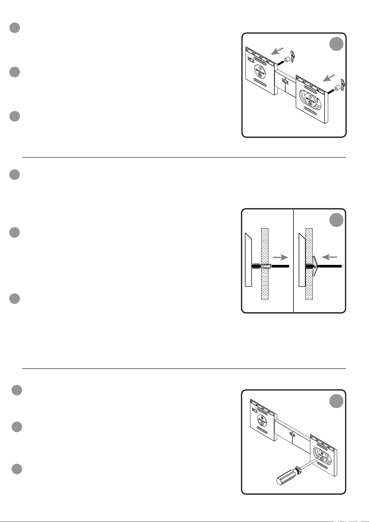
Hang ‘N’ Lock Bracket. Hold it against the wall surface where you intend to
EN
hang the product. Using a pencil, mark the screw hole positions through
the template in each cam recess. Remove the template and Hang ‘N’
Lock bracket from the wall surface prior to drilling.
Soporte Hang ‘N’ Lock. Sujételo contra la pared, en la posición donde
ES
tiene pensado colgar el armario. A través de los huecos donde irán las
levas, marque las posiciones de los oricios que va a taladrar, perforando
la plantilla con un lápiz. Quite la plantilla y el soporte Hang ‘N’ Lock de la
supercie de la pared antes de taladrar.
1
Marked Screw Position
Ferrure de xation” Hang ‘N’ Lock”. Placez-le sur le mur, à l’endroit où
FR
vous souhaitez installer l’armoire. A l’aide du crayon, repérez la position
des trous des vis sur le gabarit au niveau de l’ouverture de chaque ferru-
re. Retirer le gabarit et le support de xation Hang ‘N’ Lock du mur avant
de percer.
6
A
CAB 129 R06
Page 7

Mounting Hang ‘N’ Lock with countersink screws
Colocación del soporte Hang ‘N’ Lock mediante pernos con cabeza de arpón
Installation du système de xation à l’aide des vis à tête fraisée
Drill the marked holes to a depth of 1 3/4”. Insert the wall plugs level with
EN
the surface of the wall. (Note: if you are installing the product to a tiled
surface, insert the wall plugs below the surface of the tile to avoid
cracking, the tile) Insert the countersink screws through the Hang ‘N’ Lock
cams and loosely secure the Hang ‘N’ Lock bracket to the wall.
Taladre los agujeros en los puntos marcados, profundizando hasta 1 3/4”.
ES
Introduzca los tacos en los agujeros de manera que queden a ras de la
pared. (Nota: Si va a colgar en armario sobre azulejos, los tacos tienen
que quedar más adentro de la supercie del azulejo para evitar que se
rompa.) Introduzca los tornillos de cabeza avellanada a través de las
levas Hang ‘N’ Lock y je el soporte Hang ‘N’ Lock a la pared sin terminar
de apretarlo del todo
Percer à l’endroit des repères tracés, sur une profondeur de 1 3/4”.
FR
Introduire les chevilles de façon à ce qu’elles ne dépassent pas du mur.
(Remarque : Si vous installez l’armoire sur une surface carrelée, insérez
les chevilles de façon à ce qu’elles soient en-deçà de la surface du
carreau, an d’éviter de le fendre.) Introduire les vis à tête fraisée dans
les plaques de xation et serrer légèrement le système de xation Hang
‘N’ Lock au mur.
2
O
M
B
With the Hang ‘N’ Lock bracket loosely attached to the wall, adjust for
EN
height and level by rotating the cams with a coin or at head
screwdriver, then fully tighten the mounting screws using a philips
screwdriver, to securely x the bracket into position.
Turn to page 9 to continue installation.
Al quedar un poco suelto, podrá ajustar la altura y el nivel girando las
ES
levas con una moneda o con un destornillador plano. Una vez hecho
esto, termine de apretar los tornillos de montaje con un destornillador de
estrella para que el soporte quede bien jado en la posición denitiva.
Para continuar la instalación, vaya a la página 9.
Le système Hang ‘N’ Lock n’étant que provisoirement xé au mur, régler
FR
la hauteur et le niveau en tournant les excentriques à l’aide d’une pièce
de monnaie ou d’un tournevis à tête plate. Puis serrer à fond les vis de
xation à l’aide d’un tournevis Philips, de façon à xer dénitivement le
support en place.
Voir page 9, la suite de la procédure d’installation.
Installing Hang ‘N’ Lock with toggle bolts
Colocación del soporte Hang ‘N’ Lock mediante pernos con cabeza de arpón
Installation du système de xation à l’aide de boulons à ailettes
3
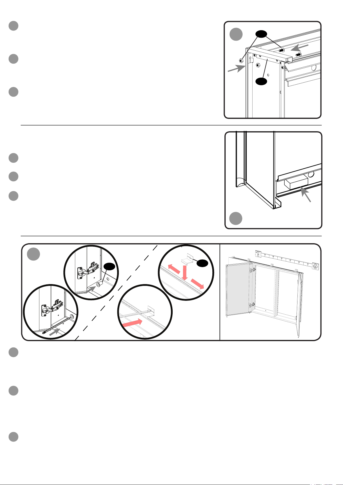
Dis-assemble the toggle bolts by unwinding the spring loaded wall braces
EN
and plugs from the threaded bolt.
Quite la cabeza de arpón y el tope de los pernos desenroscando las
ES
aletas con muelle.
Démonter les boulons à ailettes en dévissant l’ailette à ressort et
FR
l’entretoise.
7
L
4
CAB 129 R06
Page 8
Drill the holes with an 27/64” drill bit.
EN
(Note: If you are tting the product to a tiled surface, a ceramic drill bit
should be used.) Insert the treaded bolt through the Hang ‘N’ Lock cams
and reattach the plugs and spring loaded braces onto the bolts from the
back of the Hang ‘N’ Lock bracket.
Taladre los oricios con una broca de 27/64”.
ES
(Nota: si va a colgar el armario sobre azulejos, tiene que utilizar la broca
para supercies de cerámica.) Introduzca el perno roscado a través de
las levas Hang ‘N’ Lock y luego vuelva a colocar los topes y las aletas
con muelle en los pernos por el otro lado del soporte Hang ‘N’ Lock.
Percer les trous à l’aide d’un foret de 27/64”.
FR
(Remarque : Si vous xez l’armoire sur une surface carrelée, il est
conseillé d’utiliser un foret céramique.) Introduire le boulon leté dans les
excentriques Hang ‘N’ Lock et remettre l’entretoise et l’ailette à ressort sur
le boulon par l’arrière de la xation Hang ‘N’ Lock.
Push the spring loaded wall braces on the toggle bolts through the drilled
EN
holes (Note: Please ensure there is sufcient distance for the wall braces
to pass through the drilled hole in order for them to spring open and
support the weight of the cabinet when hung in position.) and loosely
secure the Hang ‘N’ Lock bracket to the wall surface using a Philips
screwdriver. Please ensure the plugs are pushed into the drilled hole to ll
the void between the drilled holes and the toggle bolts.
Comprima las aletas con muelle contra los pernos para poderlas
ES
introducir dentro de los agujeros taladrados. (Nota: Asegúrese de que
hay suciente distancia para que las aletas pasen por los agujeros y, al
llegar al otro lado, se abran, permitiendo así soportar el peso del armario
una vez colgado.) A continuación, je el soporte Hang ‘N’ Lock a la pared
con un destornillador de estrella, pero no lo apriete del todo. Introduzca
los topes dentro del agujero taladrado para llenar el espacio que queda
entre el oricio y el perno de cabeza de arpón.
5
1. 2.
6
Amener les ailettes à ressort en contact avec les boulons à travers les
FR
trous percés. (Remarque : Vérier que la distance est sufsante pour
que les ailettes passent par le trou percé de façon à ce qu’elles puissent
s’ouvrir sous l’effet du ressort et supporter le poids de l’armoire, une fois
celle-ci xée.) Puis serrer grossièrement la xation Hang ‘N’ Lock au
mur à l’aide d’un tournevis Philips. Vérier que les entretoises sont bien
enfoncées dans le trou de façon à combler le vide entre les trous et le
boulon à ailettes.
With the Hang ‘N’ Lock bracket loosely attached to the wall, adjust for
EN
height and level by rotating the cams with a coin or at head
screwdriver, then fully tighten the mounting screws using a philips
screwdriver, to securely x the bracket into position.
Al quedar un poco suelto, podrá ajustar la altura y el nivel
ES
girando las levas con una moneda o con un destornillador plano. Una vez
hecho esto, termine de apretar los tornillos de montaje con un destor-
nillador de estrella para que el soporte quede bien jado en la posición
denitiva.
Le système Hang ‘N’ Lock n’étant que provisoirement xé au mur, régler
FR
la hauteur et le niveau en tournant les excentriques à l’aide d’une pièce
de monnaie ou d’un tournevis à tête plate. Puis serrer à fond les vis de
xation à l’aide d’un tournevis Philips, de façon à xer dénitivement le
support en place.
8
7
CAB 129 R06
Page 9
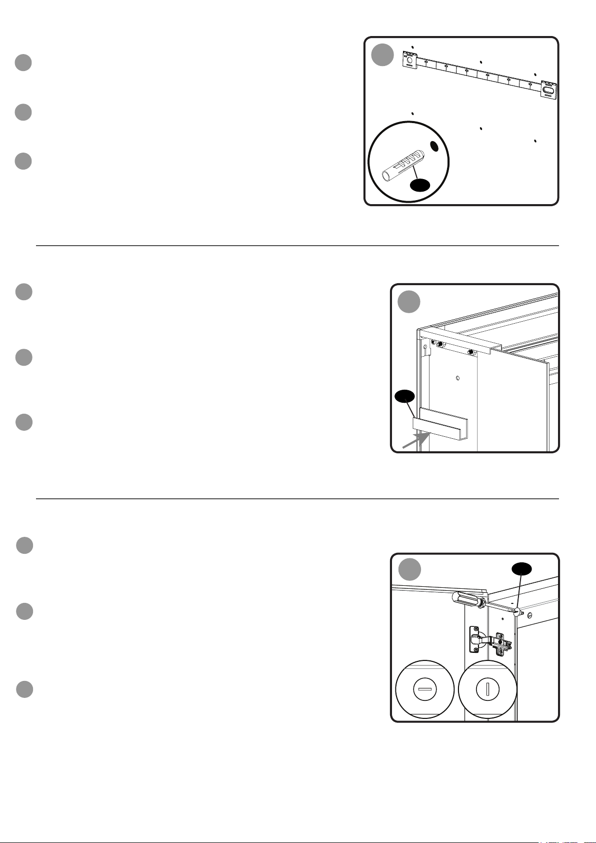
Use a philips screwdriver and adjustable wrench to t the side mirror
EN
brackets onto the cabinet prior to hanging. Align the brackets with the corresponding holes on the cabinet and secure the brackets in position using
the bolts and locking nuts provided.
Use un destornillador de estrella y una llave para colocar los soportes
ES
laterales del espejo en el armario antes de colgarlo. Alinee los soportes
con los oricios correspondientes del armario y fíjelos en su posición
utilizando los pernos y las tuercas incluidas.
A l’aide d’un tournevis Philips et d’une pince, xer les prolés latéraux des
FR
miroirs sur l’armoire avant de mettre celle-ci en place. Aligner les prolés
sur les trous correspondants, sur l’armoire et xer les pattes de xation
en place à l’aide des vis et écrous fournis.
Stick one foam pad next to each of the three large holes at the bottom of
EN
the cabinet.
Coloque una almohadilla de espuma en cada uno de los tres oricios
ES
grandes que hay en la parte inferior del armario.
8
P
D
Coller un patin en mousse à côté de chacun des trois gros orices percés
FR
en bas de l’armoire.
9
10
1.
I
2.
The cabinet has been supplied with L shaped brackets for use when surface mounting. Insert the brackets into the
EN
slot positioned in the centre of the cabinet top channel and slide them left and right until they are evenly spaced for
solid walls, or aligned with the solid wood frame for hollow walls. Push the three plastic collets into the holes at the
bottom of the cabinet. Use a pencil to mark the xing screw positions on the wall through the holes in the plastic
collets and the L shaped brackets.
4.
3.
R
El armario incluye unos soportes en L que sirven para montarlo en supercie. Introduzca los soportes en la ranura
ES
situada en el centro del canal superior y deslícelos hacia la izquierda y hacia la derecha hasta que queden a la misma
distancia por ambos lados en el caso de colgarlo en una pared maciza, o alineados con los montantes del entramado
de madera en el caso de que lo vaya a colgar en una pared hueca. Introduzca los tres casquillos de plástico en los oricios situados en la parte inferior del armario. Con un lápiz, marque las posiciones donde irán los tornillos de jación
en la pared a través de los oricios de los casquillos de plástico y los soportes en L.
L’armoire est fournie avec des supports en L pour une xation murale. Insérer ces supports dans l’encoche se trou-
FR
vant au centre de la rainure supérieure de l’armoire et les faire coulisser à gauche et à droite jusqu’à ce qu’ils soient
équitablement espacés pour les murs pleins, ou alignés sur l’ossature en bois massif pour les murs creux. Enfoncer
les trois inserts en plastique dans les trous situés en bas de l’armoire. Utiliser un crayon pour marquer la position des
vis de xation au mur à travers les orices des inserts en plastique et des supports en L.
9
CAB 129 R06
Page 10
Remove the cabinet from the wall surface. Drill the marked holes to
EN
a depth of 1 3/4”. Insert the wall plugs level with the surface of the
wall.
Descuelgue el armario de la pared. Taladre los agujeros en los
ES
puntos marcados, profundizando hasta 1 3/4”. Introduzca los tacos
en los agujeros de manera que queden a ras de la pared.
Retirer l’armoire du mur. Percer à l’endroit des repères tracés, sur
FR
une profondeur de 1 3/4”. Introduire les chevilles de façon à ce
qu’elles ne dépassent pas du mur.
Remove the protective lm on the mirror glass spacers to reveal the
EN
adhesive pads and locate in two positions on the sidewall of the cabinet
(2 spacer per sidewall). Slide the mirror glass into the channels on the
mirror brackets.
11
Q
12
Retire la película protectora de los separadores del espejo para revelar
ES
las almohadillas adhesivas y localizar dos posiciones en los laterales del
armario (2 separadores por lateral). Introduzca el espejo por las guías de
los soportes correspondientes.
Enlever le lm de protection situé sur les xations pour miroir, de façon à
FR
dégager les pastilles adhésives et les positionner sur les parois latérales
de l’armoire (2 xations par paroi). Glisser le miroir dans les rainures
situées sur les pattes de xation du miroir.
Hang the cabinet onto the Hang ‘N’ Lock bracket. Align the holes in the
EN
plastic collets with the drilled holes at the base of the cabinet, then
secure in position by inserting the two locking studs through the holes
inside the top of the cabinet. Rotate the studs 90 degrees clockwise to
lock into position.
Vuelva a colocar el armario en el soporte Hang ‘N’ Lock. Alinee los
ES
oricios de los casquillos de plástico con los taladros perforados en la
base del armario. Luego, fíjelo en su posición introduciendo los dos
pernos de bloqueo a través de los oricios que hay en la parte interior
superior del armario. Gire los pernos 90 grados en el sentido de las
agujas del reloj para bloquearlos.
F
13
C
Replacer l’armoire sur le support de xation Hang ‘N’ Lock.
FR
Aligner les trous des inserts en plastique sur les trous percés, dans la
partie inférieure de l’armoire puis la mettre en place en
introduisant les deux tétons de blocage dans les trous dans la
partie supérieure de l’armoire. Tourner les tétons de blocage de 90° vers
la gauche pour les bloquer en position.
10
UNLOCKED LOCKED
CAB 129 R06
Page 11

Insert the domed screws through the plastic collets and using a philips
EN
screwdriver secure the screws in position. DO NOT OVERTIGHTEN.
Place the decorative caps over the plastic collets to conceal the
screw xings. Insert the domed screws through the L shaped brackets
and using a philips screwdriver secure the screws in position. DO NOT
OVERTIGHTEN.
Introduzca los tornillos de cabeza redonda a través de los casquillos de
ES
plástico y apriételos con un destornillador de estrella.
NO LOS APRIETE MÁS DE LA CUENTA. Coloque los embellecedores
en los casquillos de plástico para ocultar los tornillos. Introduzca los
tornillos de cabeza redonda a través de los soportes en L y apriételos con
un destornillador de estrella. NO LOS APRIETE MÁS DE LA CUENTA.
Introduire les vis à tête bombée dans les inserts en plastique et à l’aide
FR
d’un tournevis Philips, serrer les vis.
NE PAS TROP LES SERRER. Mettre les caches de propreté sur les
inserts en plastique an de cacher les vis de xation. Insérer les vis à tête
bombée dans les supports en L et les xer à l’aide d’un tournevis cruciforme. NE PAS SERRER TROP FORT.
14
N
I
N
Once secured into position hide the unused recessed cabinet holes by
EN
using the small hole caps provided.
Una vez colocado el armario en su posición, oculte los oricios que sirven
ES
para el montaje empotrado. Para ello, coloque los embellecedores
suministrados en los oricios que no se utilizan.
Une fois l’armoire installée, cacher les trous inutilisés à l’aide des petits
FR
caches de propreté fournis.
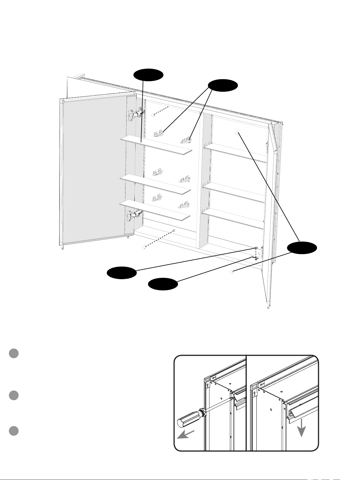
Locate the shelf brackets into the holes situated on the sidewall of the
EN
cabinet. Determine a suitable shelf position within the cabinet and press
the brackets into place. Clip the glass shelves into the brackets to
complete the cabinet assembly.
Coloque los soportes para los estantes en los oricios situados en los
ES
laterales del armario. Cuando haya decidido la posición de los estantes
apriete los soportes para jarlos. Encaje los estantes de cristal en los
soportes para terminar el montaje del armario.
15
K
G
16
Placer les supports d’étagère dans les trous situés sur la paroi intérieure
FR
de l’armoire. Choisir la position la mieux adaptée à l’intérieur de l’armoire
et mettre les supports en place. Fixer les étagères sur les supports pour
terminer l’installation.
11
H
CAB 129 R06
Page 12
Recess Mounting Assembly
Montaje empotrado
Éléments pour montage encastré
H (x9)
G (x18)
K (x4)
N (x6)
Pre-installation guide for recess mounting the cabinet
Guía de preinstalación para montar el armario empotrado
Préparation pour l’encastrement de l’armoire
If the cabinet is to be recessed mounted it is imperative
EN
that the 45 degree hanging prole is removed from the
cabinet prior to installation. To remove the 45 degree
prole unfasten the screws which secure the prole in
position and remove from the cabinet
Si va a montar el armario empotrado, es necesario retirar
ES
el perl de 45 grados del armario antes de realizar la
instalación. Para retirar el perl de 45 grados, primero
aoje los tornillos que sujetan el perl.
J (x6)
Si l’armoire doit être encastrée dans le mur, il est
FR
impératif d’enlever l’équerre à 45° xée sur l’armoire
avant d’installer celle-ci. Pour retirer l’équerre de 45°,
enlever les vis de xation de l’équerre puis enlever cette
dernière.
12
CAB 129 R06
Page 13
Installation Guide - Recess mounting the cabinet
Guía de instalación - Montaje empotrado
Guide d’installation – Armoire encastrée
Position and tape the cabinet template in the desired location
EN
ensuring the template is level.
Use a stud and cable detector to identify the location of wall studs and
electric cables or cut a small hole within the boundary of the template
to identify internal obstructions.
IMPORTANT: Before cutting it is imperative that no
obstacles (plumbing or electrical ttings) are located
behind the intended cutting area.
If needed relocate the template to avoid pipework or cables.
Coloque la plantilla del armario en la posición deseada y fíjela con cinta
ES
adhesiva cuando esté bien nivelada.
Utilice un detector para localizar los montantes y los cables eléctricos que pueda haber dentro de la pared. Otra opción es practicar un
pequeño agujero en la pared dentro del perímetro de la plantilla para
comprobar si hay obstrucciones.
623MM
(24.5”)
360MM
(14.17”)
EXAMPLE
1
IMPORTANTE: Antes de cortar, debe estar completamente seguro de
que no hay ningún obstáculo (tuberías o instalaciones eléctricas) tras
la zona que va a cortar.
Si es necesario, cambie la plantilla de lugar para evitar dichos obstáculos.
Positionner le gabarit et le xer à l’aide de ruban adhésif à l’endroit désiré en
FR
veillant à ce qu’il soit bien droit et de niveau.
A l’aide d’une tige et d’un détecteur de câble, repérer la
position des montants et des câbles électriques ou faire une petite
découpe à l’intérieur des limites du gabarit pour repérer la position des
câbles et autres éléments éventuels.
IMPORTANT : Avant de faire la découpe nécessaire pour
installer l’armoire, vous devez impérativement vous assurer
qu’il n’y a aucun élément (plomberie ou installation électrique) dans la
partie où vous allez effectuer la découpe.
Si nécessaire, déplacer le gabarit pour éviter de percer à un endroit où sont
encastrés des canalisations ou des câbles.
13
CAB 129 R06
Page 14

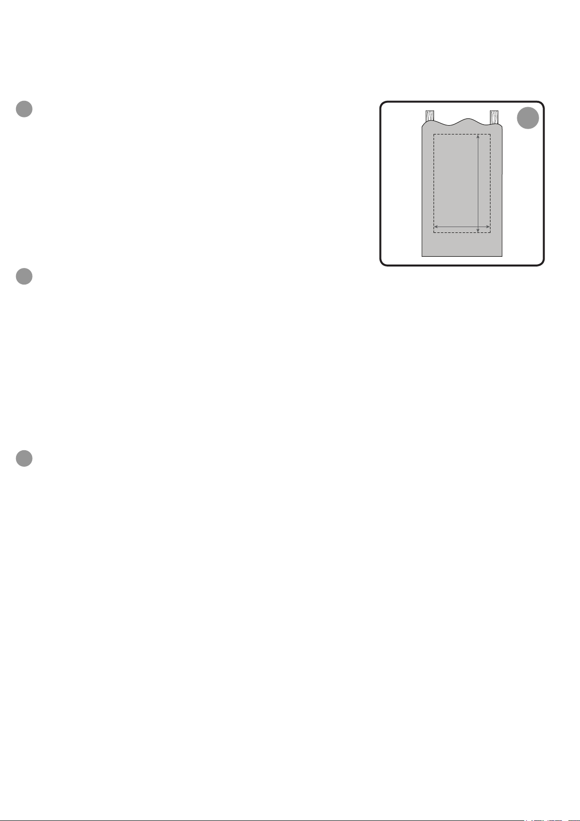
Using the dotted line printed on the template cut out the aperture for
EN
the cabinet.
Cutout sizes for reference are as follows:
PD500000 Tri-View Cabinet - 1205mm x 747mm (47 7/16” x 29 7/16”)
Recorte el agujero para empotrar el armario siguiendo la línea de puntos
ES
de la plantilla
Los tamaños del agujero para los diferentes modelos son los siguientes:
Armario de triple visión PD500000 - 1205mm x 747mm (47 7/16” x 29 7/16”)
Faire la découpe nécessaire pour installer l’armoire en suivant les pointillés
FR
tracés sur le gabarit.
Les dimensions de la découpe sont les suivantes selon le modèle d’armoire:
Armoire à trois faces PD500000 - 1205mm x 747mm (47 7/16” x 29 7/16”)
2
Frame the cutout opening to provide a mounting surface for the
EN
recessed cabinet.
Enmarque el agujero de la pared para crear una supercie de montaje
ES
para el armario empotrado.
L’encadrement autour de l’ouverture servira de support pour xer l’ar-
FR
moire encastrée.
Place the cabinet in the cutout and hold in position.
EN
(Note: the cabinet is symmetrical so it can be inverted and placed into the
cut-out allowing the centre door to hinge on either the left or right side.)
3
4
Coloque el armario en el agujero y sujételo en esta posición.
ES
(Nota: El armario es simétrico, por lo que se puede invertir y colocar en
los oricios marcados con la plantilla de manera que las bisagras de la
puerta central queden a la izquierda o a la derecha).
Placer l’armoire dans l’ouverture découpée et la maintenir en position.
FR
(Remarque : l’armoire étant symétrique, il est possible de la retourner
avant de la placer dans l’ouverture découpée de façon à ce que la porte
centrale s’ouvre vers la gauche ou la droite).
14
CAB 129 R06
Page 15

Ensure the cabinet is level within the cut out and with the dome head
EN
xing screws provided secure the cabinet into position through the
mounting holes and into the wall studs. (Note: the cabinet can be secured
to the wall studs using the mounting holes situated in the top, base or
sidewalls) DO NOT OVER TIGHTEN THE SCREWS.
Asegúrese de que el armario esté nivelado dentro del agujero de la pared
ES
y, con los tornillos de cabeza redonda suministrados, je el armario a los
montantes de la pared a través de los oricios de montaje. (Nota: El
armario se puede jar a los montantes de la pared a través de los
oricios de montaje situados en la parte superior, en la base o en los
laterales.) NO APRIETE LOS TORNILLOS MÁS DE LA CUENTA.
Vérier que l’armoire est bien droite par rapport à la découpe et la xer à
FR
l’aide des vis à tête bombée fournies, que l’on insérera dans les trous de
montage et dans les montants du mur. (Remarque : L’armoire peut être
xée au montant en utilisant les trous de montage situés dans la partie
supérieure, à la base ou dans les parois latérales.)
NE PAS TROP SERRER LES VIS.
Once secured into position hide the remaining un-used holes using the
EN
large and small hole caps provided.
Una vez colocado el armario en su posición, oculte los oricios que no
ES
utilice con los embellecedores grandes y pequeños.
5
N
6
J
Une fois l’armoire installée, cacher les trous inutilisés à l’aide des petits et
FR
des grands caches de propreté fournis.
Locate the shelf brackets into the holes situated on the sidewall of the
EN
cabinet. Determine a suitable shelf position within the cabinet and press
the bracket into place. Clip the glass shelves into the brackets to
complete the cabinet assembly.
Coloque los soportes para los estantes en los oricios situados en los
ES
laterales del armario. Cuando haya decidido la posición de los estantes,
apriete los soportes para jarlos. Encaje los estantes de cristal en los
soportes para terminar el montaje del armario.
Placer les supports d’étagère dans les trous situés sur la paroi intérieure
FR
de l’armoire. Choisir la position la mieux adaptée à l’intérieur de l’armoire
et mettre les supports en place. Fixer les étagères sur les supports pour
terminer l’installation.
K
G
7
H
EN
ES
FR
Screw
Antornillar
Visser
S
S
S
15
S
CAB 129 R06
Page 16

Hinge Adjustment Guide
Bisagra Guía de Ajuste
Charnière Guide Ajustement
To move the door position forwards
EN
adjust as shown.
Para mover la posición de la
ES
puerta hacia delante Ajuste según se
muestra.
Pour déplacer la position de la porte
FR
avant d’ajuster comme le montre.
To move the door position up or down
EN
adjust as shown.
Para mover la posición de la puerta
ES
hacia arriba o hacia abajo Ajuste
según se muestra.
Pour déplacer la position de la porte
FR
vers le haut ou vers le bas Régler
comme illustré.
To move the door position left or right
EN
adjust as shown.
Para mover la posición de la puerta
ES
izquierda o derecha ajustan como se
muestra.
Pour déplacer la position de la porte
FR
gauche ou la droite Régler comme
illustré.
For details of the other items in the Jacuzzi® product offering please visit our website:
www.jacuzziluxurybath.com
Si necesita más detalles de otros artículos del catálogo de Jacuzzi®, visite nuestro sitio web:
www.jacuzziluxurybath.com
Pour plus de détails sur les autres produits de la gamme Jacuzzi®, consultez notre site web:
www.jacuzziluxurybath.com
Jacuzzi Luxury Bath, 14525 Monte Vista, Chino, CA 91710 USA
Tel: 1-800-288-4002
6am – 5pm PT, M-F
©2017 Jacuzzi Inc. All rights reserved.
16
CAB 129 R06
Page 17

One Year Warranty on Jacuzzi® Branded Medicine Cabinets
WARRANTY COVERAGE
Jacuzzi Luxury Bath (“Company”) offers a one year warranty to the original purchaser (“user”) of a Jacuzzi® branded
medicine cabinet for personal or single family residential use, subject to the following terms, conditions and limitations.
The Company will repair or replace, at its sole option, the medicine cabinet or its component parts in accordance
with the terms, conditions and limitations set forth in this limited warranty. Units in commercial use are excluded from
any warranty coverage whatsoever. PLEASE READ THIS ENTIRE LIMITED WARRANTY, AS EXCLUSIONS AND
CONDITIONS APPLY. All portions of the medicine cabinet are warranted against defects in material and workmanship
for one year from date of purchase. This warranty does not apply to any display models or to any options or accesso-
ries not specically mentioned herein. Warranty coverage begins on the date the unit was originally purchased by the
user. The warranties provided by Company do not cover labor, and are parts only warranties.
The components referenced above and coverage of this warranty are for defects in material or workmanship, and not
damage caused by installation, neglect, misuse, abuse, hard water conditions, optional equipment, the unit’s prior
usage as an operational display, defects that should have been discovered before installation, or failure to follow the
instructions and warnings set forth in the owner’s manual, including but not limited to cleaning of the accessory and
its component parts, such as using chemicals, abrasives, acids, solvents, etc. Inspecting the unit prior to installation
is the responsibility of the user, as well as the installer or building contractor who acts on behalf of the user. In the
event of a problem, the unit must not be installed. The Company is not responsible for failures or damage that could
have been discovered, repaired, or avoided by proper inspection and testing prior to installation. Damage occurring
in transit is the responsibility of the carrier. Damage occurring to the unit during installation is the responsibility of the
installer, building contractor and/or user, and damage occurring thereafter is the responsibility of the user. Any replace-
ment parts shall be covered only by the original equipment manufacturer warranty, if any. The distributor, dealer and
user are responsible for knowing local code requirements and notifying the installing contractor of these requirements
at the time of purchase. The Company is not responsible for costs to modify any product to obtain any code approval,
such as city, county, or state building codes in U.S.A. or federal, municipal, provincial or other codes in Canada and
Mexico. To make a claim, user must rst contact Company and thereafter return any part claimed to be defective
within the warranty period to Company, freight prepaid. Proof of purchase (original sales receipt) from the original purchaser must accompany all warranty claims. Defects or damage caused by the use of other than genuine Company
parts is not covered by this warranty.
IMPLIED WARRANTIES OF MERCHANTABILITY AND FITNESS FOR A PARTICULAR PURPOSE ARE DISCLAIMED ALTOGETHER OR TO THE FULLEST EXTENT ALLOWED BY LAW. This warranty takes the place of all
other warranties, express or implied, in fact or at law, including implied warranties of merchantability and tness for a
particular purpose. Company reserves the right to use replacement parts that may be different from the part(s) that
accompanied the original medicine cabinet, including but not limited to different in appearance, conguration, performance and/or structure. No agent, dealer, distributor, service company or other party is authorized to change, modify
or extend the terms of this limited warranty in any manner whatsoever. In addition, THE COMPANY WILL NOT BE
RESPONSIBLE FOR INCIDENTAL OR CONSEQUENTIAL DAMAGES or losses arising from any cause including but
not limited to its own negligence. This exclusion applies even if Company was advised in advance of the possibility
of such damages. This limited warranty does not include labor, transportation, or other costs incurred in the removal
and/or reinstallation of the original unit and/or installation of a replacement unit; any costs relating to obtaining access
for repair; or loss of use damage, including loss of sales, prot or business advantage of any kind under any circumstances. Accessories are excluded from any warranty coverage if any addition, deletion, or modication of any kind
whatsoever has been made to the unit (or to any component). Warranty coverage is provided in the United States of
America, Canada and Mexico only. The liability of Company under this limited warranty, if any, shall not exceed the
original amount paid for the product claimed to be defective. Dated proof of purchase of accessory is required for a
warranty claim. These disclaimers shall be equally applicable to any service provided by Company and its designated
representatives.
The Company will provide the warranty service described above when the following conditions have been met: the
failure is of the nature or type covered by the warranty; the user has informed an Authorized Jacuzzi Luxury Bath Service Agent or Warranty Service Department Representative of the nature of the problem during the warranty period;
conclusive evidence (e.g., dated proof of purchase) is provided to the foregoing by the user proving that the failure
occurred or was discovered within the warranty period; and, an authorized independent service person or Company
representative has been permitted to inspect the unit during regular business hours within a reasonable time after the
problem was reported by the user. In order to obtain warranty service, contact Jacuzzi Luxury Bath at: www.jacuzzi.
com or Warranty Service Department, 14525 Monte Vista Avenue, Chino, California 91710, (800) 288-4002.
All replacement parts, equipment, and repairs shall assume the remaining warranty period of the part(s) replaced.
The Company’s warranty obligation shall be discharged upon tender of replacement or repair. The customer’s refusal
to accept the tender terminates the Company’s warranty obligation.
LEGAL RIGHTS: This Limited Warranty gives you specic legal rights. There are no warranties applicable to Jacuzzi® products except as expressly stated herein or as implied by applicable state and federal laws. You may also have
other rights that vary from state to state. Some states do not allow limitations on how long an implied warranty lasts,
disclaimer of certain warranties, or the exclusion or limitation of incidental damages, so some of the above limitations
may not apply to you. Company will not be responsible for any statements or representations made in any form that
go beyond, are broader than or are inconsistent with any authorized literature or specications furnished by the Company.
CAB 129 R06
 Loading...