

Page 1
OPTICA
SHOWER MIXER/TRANSFER VALVE
INSTALLATION INSTRUCTIONS
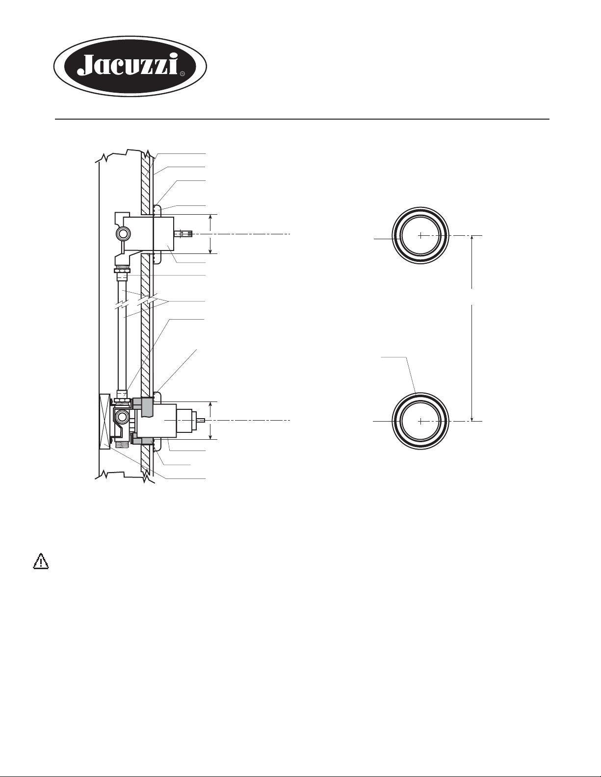
FINISHING WALL
TILE (FINISH SURFACE)
SEALANT (SILICONE) ON BACKSIDE OF
FACEPLATE
FACEPLATE (SEALANT NOT PROVIDED)
2-3/8" DIA.
GASKET
TRIM SLEEVE OF TRANSFER VALVE
LEFT-HAND THREAD TO
SWEAT ADAPTOR (NOT PROVIDED)
COPPER PIPE (NOT PROVIDED)
FEMALE THREAD TO SWEAT ADAPTOR
(NOT PROVIDED)
™
300
REAR VIEW
4-15/16" MINIMUM
SEALANT (100% SILICONE) ON BACKSIDE OF
FACEPLATE (SEALANT NOT PROVIDED)
NOTE: WHEN INSTALLING BAND, RING, ROPE
OR FACETED HANDLE, PULL TRIM SLEEVE OUT
TO MEET HANDLE.
2-3/8" DIA.
TRIM SLEEVE
PLASTER GUARD
WOOD CROSS MEMBER
GASKET
REAR VIEW
(FRONT HAS RED
AND BLUE DOTS)
OPTICA 300
WARNING: This system/device must be set by the installer to ensure safe, maximum temperature. Any change in
the setting may raise the discharge temperature above the limit considered safe and may lead to scalds.
CAUTION: As the installer of this valve, it is your responsibility to properly install and adjust this valve per the
instructions given. This valve does not automatically adjust for inlet temperature changes, therefore, it is necessary
to adjust the Rotational Limit Stop at the time of installation. You must inform the owner/user of this requirement by
following the instructions below. After installation and adjustment, you must write in the temperature and the date
you adjusted the Rotational Limit Stop on the warning label provided and apply or attach it to the hot water heater.
Be sure this instruction sheet is delivered to the owner/user.
WARNING: This pressure balanced bath valve is designed to minimize the effects of outlet water temperature
changes due to inlet pressure changes, commonly caused by dishwashers, washing machines, toilets and the like.
It may not provide protection from scalding when there is a failure of other temperature controlling devices elsewhere
in the plumbing system if the Rotational Limit Stop is not properly set, or if the hot water temperature is changed after
the Rotational Limit Stop is set, or if the water inlet temperature changes due to seasonal changes.
INSTALLER: LEAVE THIS INSTRUCTION MANUAL FOR OWNER'S/USER'S REFERENCE
©1995 Jacuzzi Whirlpool Bath G570000 D 12/06 Page 1
Page 2
INSTALLATION INSTRUCTIONS
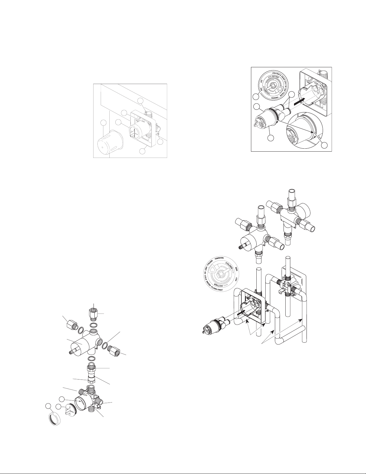
4
1
2
3
3
5
WARNING: Failure to follow these instructions could
prevent the mixer/transfer valve from functioning
properly.
1. Shut OFF water supplies.
2. Install the body (1) so the surface of the fi nished
wall is fl ush with the front of the plasterguard (2).
The plasterguard is
mounted on the body
using the two stringer
mounting holes (3) on
the bracket. NOTE:
Remove cover (4) to
access body mounting holes. Ensure the
word "UP" (5) is on top
of the valve body when
installing.
3. Install transfer valve
so that the transfer valve inlet connects to the top port
of the mixer valve. See below. The transfer valve must
be located at least 4-15/16" (center to center) away from
the mixer valve. A left-hand thread to sweat adaptor
and gasket are required for this connection. Use a 1/2"
copper pipe size, a taper to sweat adaptor, and a female
thread to sweat adaptor to fi nish the connections from
transfer valve to mixer valve. Copper pipe and adaptors
not provided.
Connect hot and cold supply lines to left and right inlets of
mixer body. Left is hot and right is cold (as viewed from
front). Threaded inlets are 1/2" NPT (iron pipe size). Use
an approved thread sealant for threaded connections.
Remove bonnet (1) and test cap (2) before soldering.
Leave screen (3) installed. WARNING: Avoid soldering
at high temperature. Exposure to high temperatures
may damage screen.
4. Rotate the cartridge (1) so the words “hot side” (2)
appear on the left. Insert cartridge into valve body as
shown. Make sure the cartridge tubes and o-rings (3)
are properly seated in holes at the base of the body.
Ensure the keys on the body are fully engaged with the
slots in the body (4).
For s howe r h ead
installation connect
plumbing from top
outlet of transfer valve
to shower head arm
with proper fi ttings. Do
2
4
3
NOT install the shower
head onto arm at this
time.
1
4
5. For cascade installation connect right outlet of transfer
valve to cascade line. The left outlet is for body spray jets.
Plug unused ports if other arrangements are used.
NORMAL INSTALLATION
(CHANGES NOT REQUIRED)
REVERSE
INSTALLATION
TRANSFER VALVE
TRANSFER
VALVE
TO
BODY
SPRAY
TRANSFER
VALVE
*FEMALE
THREAD TO
SWEAT ADAPTER
HOT IN
3
1
2
OPTICA 300 CONNECTIONS
TO SHOWER
*NOT PROVIDED
M
xF ADAPTER (3)
COPPER GASKET (4)
TO
CASCADE
*LEFT-HAND
THREAD TO
SWEAT ADAPTER
*COPPER PIPE
COLD IN
MIXER VALVE
COLD
HOT
BACK TO BACK OR REVERSE INSTALLATION
6. For back to back or reverse installations only
(hot on right and cold on left), follow instructions below.
If you are not making a reverse or back to back installation skip Steps 6 and 7 and continue with Step 8.
Make sure water supplies are OFF. Install mixing valve
as directed in the previous steps.
7. For back to back or reverse installations only
(hot on right and cold on left). Connect hot and cold
supply lines to left and right inlets of mixer body. Right
is hot and left is cold (as viewed from front).
Page 2 ©1995 Jacuzzi Whirlpool Bath G570000 D 12/06
Page 3

8. Slide bonnet nut (1) over the cartridge and thread
onto the body. Hand tighten securely.
1
9. Flush your system prior to installing the shower
head. Place handle on valve stem and turn handle to
full mix position. Turn ON water supplies, check for
leaks and let lines fl ush for one minute without moving
faucet handle. Divert water to shower head and fl ush
for 30 seconds. This will remove any debris from lines
which can damage internal parts of the faucet and
create leaks. After fl ushing, shut OFF water at faucet.
Remove handle and attach escutcheon. Attach shower
head.
CAUTION: Connection of deck-mount spouts to in-
wall valves is not recommended. Neither is the use of
hand showers connected to bath spouts in a bath/shower
push button diverter combination.
WARNING: In some instances, setting the Rotational
Limit Stop in the hottest position (full counterclockwise) could result in scald injury. It is necessary to
adjust the Rotational Limit Stop so that the water
coming out of the valve will not scald the user when
the handle of the valve is rotated to the hot side.
Adjust rotational limit stop. After water has run a suffi cient
length of time so that cold water is as cold as it will get,
and hot water is as hot as it will get, place handle back
on stem and rotate handle counter clockwise to the hottest position. Place a thermometer in a plastic tumbler,
and hold the tumbler in the water stream. Record the
temperature reading and note or mark the position of
the Rotational Limit Stop on the mating part. If the water
temperature is above 120°F the Rotational Limit Stop
must be rotated clockwise to reduce the temperature
(See illustration).
Remove the Rotational Limit Stop and replace it one tooth
counter clockwise for every 6° F (approximate) reduction
in temperature that must be made. If water temperature
is below 90° F, rotate the stop counter-clockwise. Repeat
as necessary. Make sure cold water fl ows from the valve
fi rst and does not exceed 120°F at the hottest fl ow. A
guide to setting the approximate outlet temperature is
included. This is only a guide and any setting must be
verifi ed by using the above procedure.
Hotter
Disc
Stem
Rotational Limit Stop
Colder
1st Position
10. IMPORTANT: The Rotational Limit Stop is used to
limit the amount of hot water available such that, if set
properly, the user will not be scalded if the handle accidentally is rotated all the way to “hot” when a person
is showering or fi lling a tub. The fi rst position allows the
LEAST amount of hot water to mix with the cold water
in the system. In the fi rst position the water will be the
coldest possible when the handle is turned all the way to
hot. As you move the Rotational Limit Stop counterclockwise, you progressively add more and more hot water
in the mix. The last position to the left will result in the
greatest amount of hot water to the mix, and the greatest risk of scald injury if someone accidentally turns the
valve handle all the way to the hot side while showering
or fi lling a tub.
©1995 Jacuzzi Whirlpool Bath G570000 D 12/06 Page 3
Page 4

HELPFUL HINTS:
1. Before removing cartridge assembly for any maintenance, be sure to note the position of the stop on the cap.
The cartridge assembly must always be put back in the same position. For normal installations, the stop on the cap
will face the left. To be safe, after you have fi nished the installation turn ON valve to make sure cold water fl ow
fi rst.
2. To remove cartridge from body, shut OFF water supplies and remove handle, trim sleeve and bonnet. Place
handle on stem and rotate clockwise while lifting cartridge out of body.
3. To remove seats and springs, remove cartridge (see above). Separate cap assembly from the housing assembly by rotating the cap counter clockwise 90 degrees. Separate cap and housing assemblies. Remove seats and
springs. Place new seats and spring. Place the largest diameter of the spring into the seat pocket fi rst and then
press the tapered end of the seal over the spring. Reassemble cartridge and replace in body following instructions
given in Step 1 above.
4. If the water in your area has lime, rust, sand or other contaminants in it, your pressure balanced valve will require
periodic inspection. The frequency of the inspection will depend on the amount of contaminants in the water. To
inspect cartridge, remove it and follow Step 1. Turn the valve to the full mix position and shake the cartridge rigorously. If there is a rattling sound, the unit is functional and can be reinstalled following instructions given in Step 1
as listed. If there is no rattle, replace housing assembly.
No adjustment to the Optica shower mixer Rotational Limit Stop should be made except by a trained installer.
CARE INSTRUCTIONS
Your Optica Faucet is designed and engineered in accordance with the highest quality and performance standards.
With proper care, it will give you years of trouble free service. Care should be given to the cleaning of this product.
Although its fi nish is extremely durable, it can be damaged by harsh abrasives or polish. To clean, wipe gently with
a damp cloth and blot dry with a soft towel.
TROUBLESHOOTING
CONDITION
Faucet leaks from bath spout/showerhead – SHUT
OFF WATER SUPPLIES
If leak persists – SHUT OFF WATER SUPPLIES
Unable to maintain constant water temperature Replace housing assembly with RP19805 or follow
REMEDY
Replace seats and springs – Repair Kit RP4993.
Check conditions of lower o-rings and replace if
necessary.
Replace housing assembly (PN D513000) – Repair Kit RP19805
Helpful Hint #4.
If your Optica 300 components do not match this unit, please contact Service Support: 1-800-288-4002
Page 4 ©1995 Jacuzzi Whirlpool Bath G570000 D 12/06
Page 5

WARNING: This is a guide to help you set the Rotational Limit Stop. This is only a guide and should be verifi ed by
following the instructions on setting the rotational limit stop given in this installation and instruction sheet.
MIX TEMPERATURE-VS-POSITION OF ROTATIONAL LIMIT STOP
APPROXIMATE MIX TEMPERATURE (°F) WITH VARYING INLET TEMPERATURES
Cold Hot
Setting of limiter
1st Position
2nd Position 50 70 50 70 70 70 40 85
3rd Position 61 79 67 83 74 89 70 101
4th Position 68 83 75 90 84 97 84 110
5th Position 74 87 85 96 91 104 95 117
6th Position 79 90 91 101 99 110 103 125
7th Position 82 93 97 104 104 115 109 130
8th Position 85 95 104 107 108 118 115 135
(Factory Set)
9th Position 89 100 117 111 115 124 124 141
10th Position 98 105 134 121 128 136 140 153
11th Position 111 115 138 133 149 151 165 172
50°F 120°F
Cold Hot
70°F 120°F
SHUT OFF ZONE: NO FLOW APPROXIMATELY 0-20 DEGREES OF HANDLE ROTATION
Cold Hot
50°F 140°F
Cold Hot
70°F 140°F
Cold Hot
50°F 160°F
Cold Hot
70°F 160°F
Cold Hot
40°F 180°F
Cold Hot
85°F 180°F
Setting of limiter
The fi rst position of the Rotational Limit Stop (the Limiter) is that position that restricts the rotation of the stem the
most and is at the maximum counterclockwise setting. According to industry standards, the maximum allowable
temperature of the water exiting from the valve is 120°F. This temperature may vary in your local area. The Rotational Limit Stop may need to be readjusted if the inlet water temperature changes. For instance, during the winter,
the cold water temperature is colder than it is during the summer which could result in varying outlet temperatures.
Typical temperature for a comfortable bath or shower is between 90°-110°F.
©1995 Jacuzzi Whirlpool Bath G570000 D 12/06 Page 5
Page 6

This page left blank.
CAUTION
Since plumbing fi ttings may contribute detectable amounts of lead to water, the following notice is required by Califor-
nia law ( Proposition 65). "This product contains a chemical known to the State of California to cause birth defects or
reproductive harm." In normal use, any lead exposure can be minimized by allowing the water to run free for several
seconds before drinking.
Proper Installation of the fi ll spout and compliance with local codes is the responsibility of the installer. Jacuzzi
Whirlpool Bath does not warrant connections of water supply fi ttings and piping, fi ll systems, or drain/overfl ow sys-
tems. Nor is it responsible for damage to the bath (or spa) which occurs during any installation procedure.
Jacuzzi Whirlpool Bath
14801 Quorum Dr., Suite 400, Dallas, TX 75254
Service Support: Call 1-800-288-4002
©1995 Jacuzzi Whirlpool Bath G570000 D 12/06
Printed on Recycled Paper
Printed in the U.S.A.
 Loading...