

Page 1
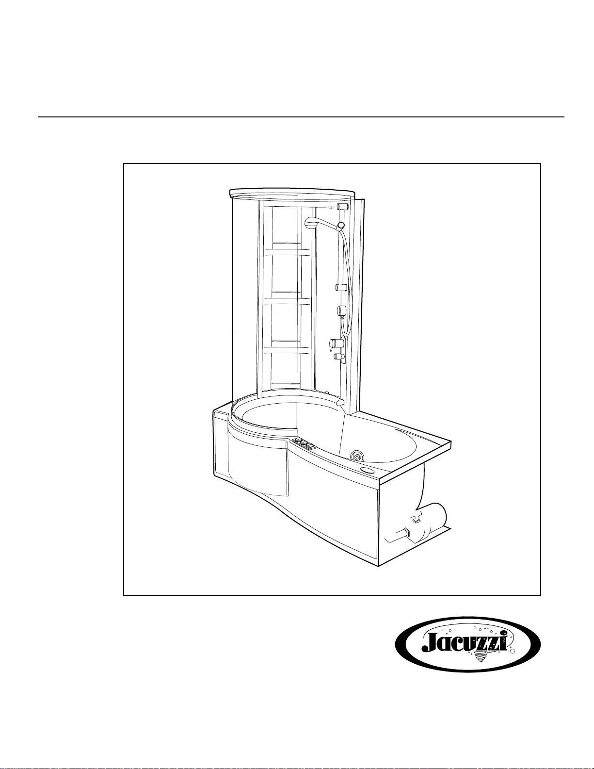
J-SHOWER TOWER
™
ENCLOSURE-Siena
INSTALLATION AND OPERATING MANUAL
™
, Merano
™
WHIRLPOOL
BATH
R
Page 2

Page 3

Important
The bathtub must be installed per installation instructions D884000 for the Merano™ or E160000 for the Siena™.
Follow the instructions to ensure that proper framing has been provided to support the J-Shower Tower. Finishing
materials must be waterproof and sealed so that spray and condensation do not cause moisture damage.
NOTE: The J-Shower Tower has been partially pre-assembled for your convenience during installation.
The installer must still follow the instructions to ensure proper installation of the tower and components
(see page 13). We recommend that two persons perform this installation.
Contents
Exploded View of J-Shower Tower ________________________________________________________ 2
Shower Tower Hardware Identification Chart __________________________________________________ 4
Tower Assembly _______________________________________________________________________ 7
Water Lines to Mixer/Diverter Valve _________________________________________________________ 10
Attaching Diverter Valve to Shower Wall _____________________________________________________ 10
Tower Installation ______________________________________________________________________ 12
Tower Disassembly______________________________________________________________________ 13
Placing Tower __________________________________________________________________________ 14
Fixed Panel Assembly____________________________________________________________________ 15
Mounting Top Ring and Wall Bracket to Tower_________________________________________________ 17
Fixed Glass Frame Attachment_____________________________________________________________ 19
Sealing and Trimming ____________________________________________________________________ 20
Attaching Face Plate _____________________________________________________________________ 21
Handle Installation_______________________________________________________________________ 21
Handle Operation _______________________________________________________________________ 22
Tools Required
1. Drill.
2. Drill bits: 3/32", 1/8", 3/16" and 5/16".
3. Flat blade screw driver, No. 1.
4. Phillips type blade screw driver, No. 2.
5. 5/16" or 8 mm deep socket or nut driver.
6. Caulking gun.
7. Sealant (100% silicone).
8. Adjustable wrenches (small and medium).
9. Allen wrenches: 1.5 mm, 2.5 mm, 3 mm and 5/64".
10. Step ladder.
1
Page 4
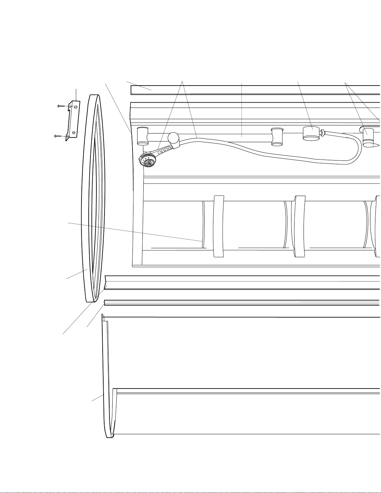
BAILS
SEE PAGE 7
WALLBAR
SEE PAGE 9
F EXTRUSION
SEE PAGE 20
L EXTRUSION
SEE PAGE 20
TOP RING
SEE PAGE 17
WALL BRACKET
SEE PAGES 17 &18
TOWER
SEE PAGE 12
HANDLE
SEE PAGE 21
HAND HELD
SHOWER,
FLEX HOSE
SEE PAGE 22
WATER INLET
SEE PAGE 8
FIXED PANEL
SEE PAGE 13 & 14
END EXTRUSION
SEE PAGE 19
2
Page 5
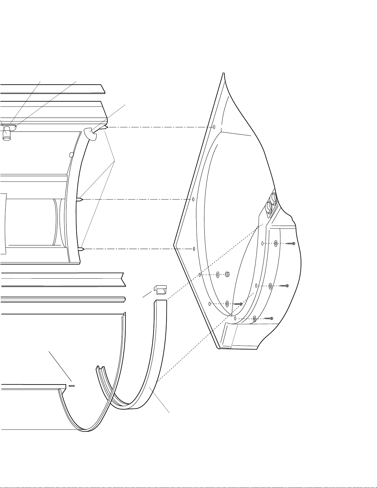
END CAP
SEE PAGE 20
BOTTOM RAIL
SEE PAGE 15 & 16
SET SCREW
SEE PAGE 16
PINS
SEE PAGE 11
FACEPLATE
SEE PAGE 21
MIXER/DIVERTER
(INCLUDING HOSE
CONNECTIONS)
SEE PAGES 10 & 11
FILL SPOUT
SEE PAGE 8
EXPLODED VIEW OF J-SHOWER TOWER
3
Page 6
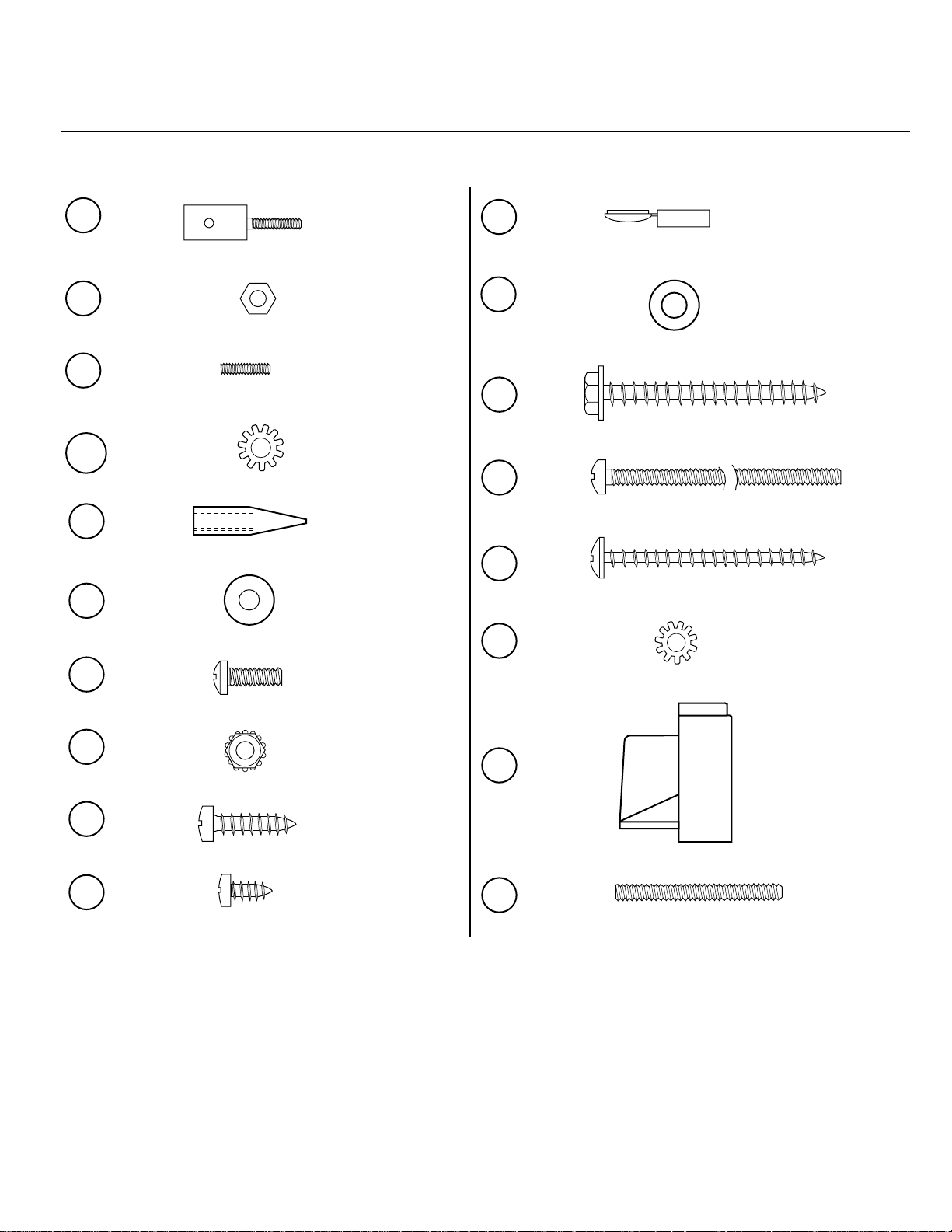
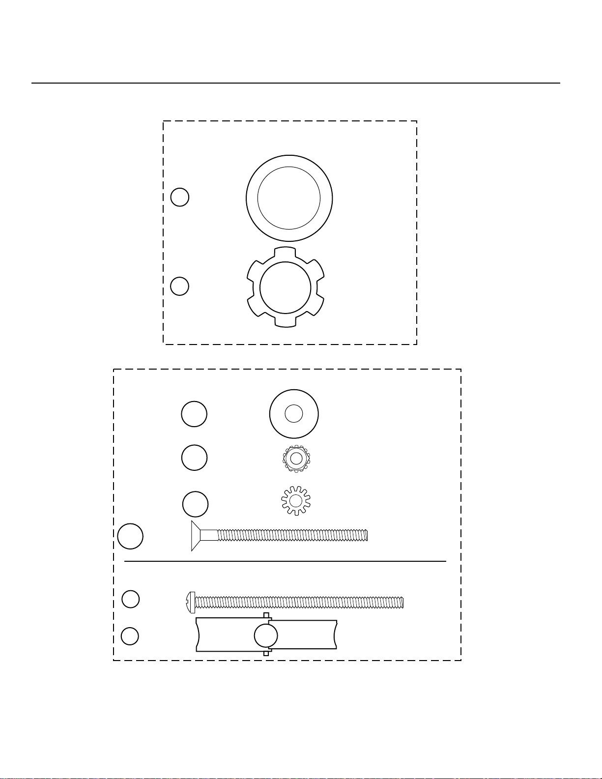
Shower Tower Hardware
Identification Chart
The diagrams for these fasteners are shown actual size for fast identification.
HARDWARE
H1
H2
H3
WB3
H4
H5
H6
BOLT
QTY.-8
NUT
QTY.-8
SCREW
QTY.-8
WASHER
QTY.-8
PIN
QTY.-3
WASHER
QTY.-10
SCREW
QTY.-3
SLOT
FASTENER
10 X32
HEX NUT
10 x 32
SET SCREW
6 x 32
EXTERNAL TOOTH
LOCK-WASHER #10
STAINLESS STEEL
PIN #8-32
.25DIA X 1"
FLAT WASHER
#8 TYPE B
STAINLESS STEEL
PAN HEAD SCREW
#8-32 x 1/2"
STAINLESS STEEL
H10
H11
H12
H13
H14
H15
COVER
QTY.-6
WASHER
QTY.-2
SCREW
QTY.-2
SCREW
QTY.-3
SCREW
QTY.-1
WASHER
QTY.-4
SCREW COVER
FLAT WASHER
#10 TYPE A
STAINLESS STEEL
SHEET MET AL
SCREW
#10-16X 2" S.S.
PAN HEAD
PHILLIPS
#8-32 x 3"
SHEET MET AL
SCREW
#8-18X 2" S.S.
EXTERNAL TOOTH
LOCK-WASHER #8
STAINLESS STEEL
H7
H8
H9
NUT
QTY.-1
SCREW
QTY.-7
SCREW
QTY.-11
HEX LOCKNUT #8-32
M4.2X19MM
STAINLESS STEEL
M3.5X9.5MM
STAINLESS STEEL
4
H16
H17
CAP
QTY. -1
SCREW
QTY.-1
LOWER TRACK
END CAP
SET SCREW
#8-32 x 1 1/2"
Page 7
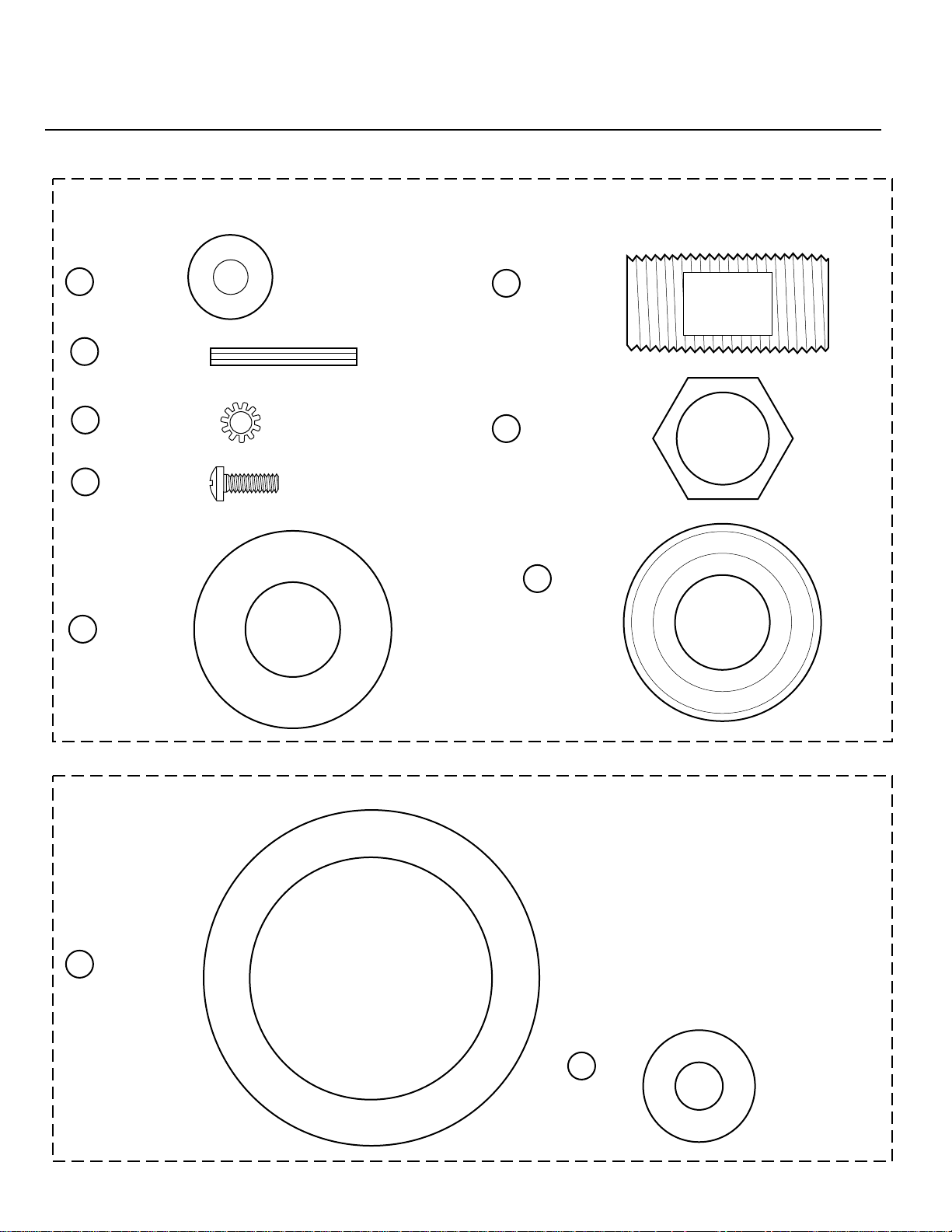
Shower Tower Hardware
Identification Chart
The diagrams for these fasteners are shown actual size for fast identification.
WATER INLET HARDWARE
WASHER
W1
QTY.-1
W2
NUT
QTY.-1
WALL BAR HARDWARE
WB1
WB2
WASHER
QTY.-2
NUT
QTY.-2
FIBRE WA SHER
1.24 DIA
LOCKNUT
1/2"-14NPT
FLAT WASHER
#10, TYPE B
HEX LOCKNUT
#10-24
WB3
WB4
SCREW
QTY.-2
PARTS NOT NEEDED
1
SCREW
QTY.-2
2
NUT
QTY.-2
WASHER
QTY.-2
EXTERNAL TOOTH
LOCK-WASHER #10
STAINLESS STEEL
FLATHEAD SCREW
#10-24 x 2 1/2"
STAINLESS STEEL
SCREW
#10-24x4"
S.S.
TOGGLE NUT
10-24
5
Page 8
Shower Tower Hardware
Identification Chart
The diagrams for these fasteners are shown actual size for fast identification.
PLUMBING HARDWARE
WASHER
P1
QTY.-2
STANDOFF
P2
QTY.-3
P3
WASHER
QTY.-3
P4
SCREW
QTY.-6
WASHER
P7
QTY.-6
FIBER WASHER .75 O.D.
EXTERNAL TOOTH
LOCK WASHER M4
PHILLIPS HEAD
SCREW M4X12
STAINLESS STEEL
RUBBER
WASHER
1.75 DIA
NIPPLE
P5
QTY.-1
LOCKNUT
P6
QTY.-1
P8
COMPRESSION
RING
QTY.-1
MIXER HARDWARE
GASKET
M1
QTY.-1
FOAM GASKET 3" O.D.
M2
GASKET
QTY.-1
6
FOAM GASKET
1" O.D.
Page 9
TOWER ASSEMBLY
1. Assemble the four (4) bails to the tower wall.
Do not overtighten the nuts on the threaded
shaft end. Overtightening may break the stud.
NUT (8)
H2
ILLUSTRATION 1
WASHER (8)
BOLT (8)
SET SCREW (8)
SHELF
H1
H3
WB3
BAIL
H1
H2
H3
WB3
BOLT
QTY.-8
NUT
QTY.-8
SCREW
QTY.-8
WASHER
QTY.-8
SLOT
FASTENER
10 X32
HEX NUT
10 x 32
SET SCREW
6 x 32
EXTERNAL TOOTH
LOCK-WASHER #10
STAINLESS STEEL
7
Page 10

2. Attach the water inlet and fill spout to the
tower wall. (See Illustration 2 and 2a.)
WATER INLET
WASHER
W1
NUT
W2
ILLUSTRA TION 2
FILL S PO UT
P7
WASHER
NUT
P6
TOWER
WALL
CAULK
TOWER
WALL
WATER
INLET
FILL SPOUT
W1
W2
WASHER
QTY.-1
NUT
QTY.-1
NIPPLE
P5
QTY.-1
FIBER WASHER
1.24 DIA
LOCKNUT
1/2"-14NPT
P5
NIPPLE
COMPRESSION
P8
RING
ILLUSTRATION 2a
P7
WASHER
QTY.-1
CAULK
RUBBER
WASHER
1.75 DIA
P6
LOCKNUT
QTY.-1
COMPRESSION
RING
QTY.-1
LOCKNUT
1/2"-14NPT
P8
8
Page 11

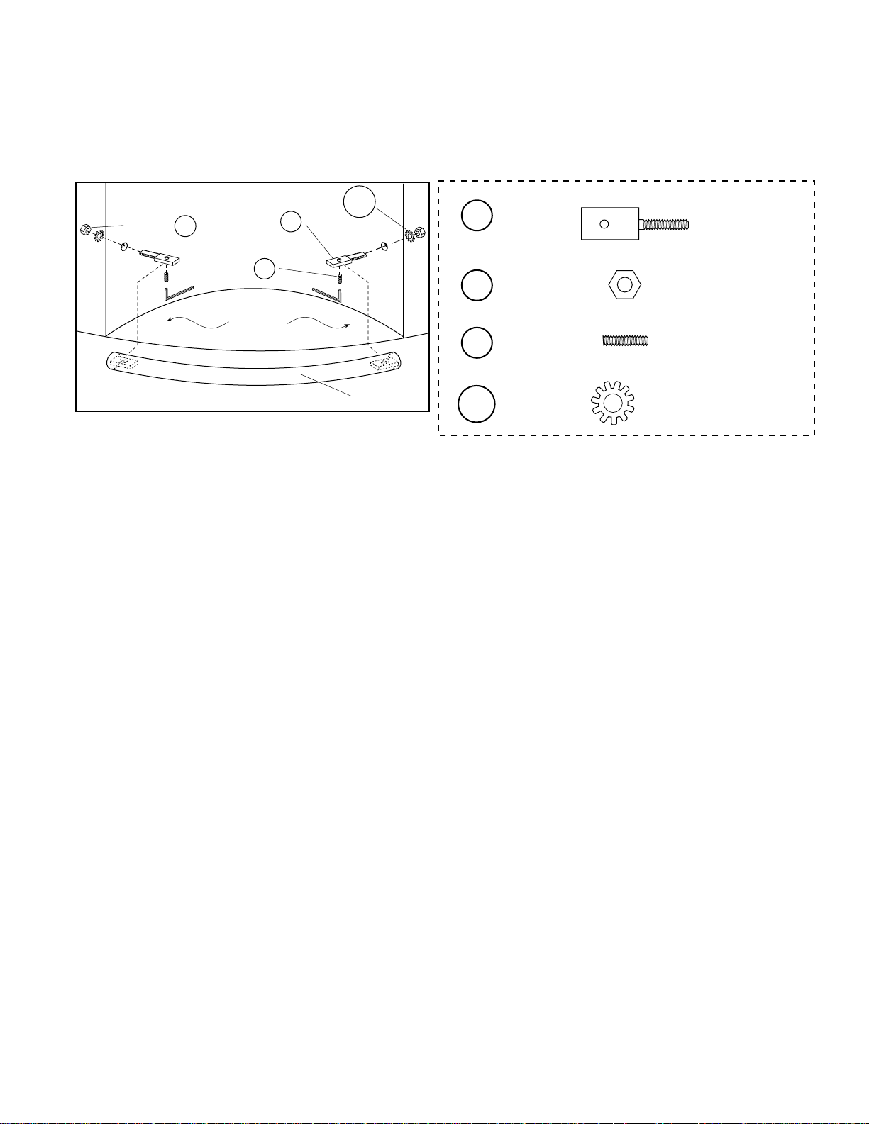
3. Attach the wallbar assembly to the tower wall.
(See Illustration 3.)
WALL BAR
1/8" BEAD OF CAULK
WALLBAR STAND-OFF
EXTERNAL TOOTH
SHOWER
WASHER
WALL
SCREW
KEP
NUT
WB2
FLAT
WASHER
WB1
WALLBAR
SHOWER HEAD
BRACKET
SOAPDISH
WB3
CAP
SIDE VIEW
OF WALLBAR
WB4
WASHER
WB1
QTY.-2
WB2
WB3
NUT
QTY.-2
WASHER
QTY.-2
SCREW
QTY.-2
WB4
PARTS NOT NEEDED
1
SCREW
QTY.-2
2
NUT
QTY.-2
FLAT WASHER
#10, TYPE B
HEX LOCKNUT
#10-24
EXTERNAL TOOTH
LOCK-WASHER #10
STAINLESS STEEL
FLATHEAD
SCREW
#10-24 x 2 1/2"
STAINLESS
STEEL
SCREW
#10-24x4"
S.S.
TOGGLE NUT
10-24
ILLUSTRA TION 3
9
Page 12

WATER LINES TO MIXER/DIVERTER VALVE
M/F 90° ELBOW
COUPLING
M/F 90° ELBOW
(LOCATED IN
PLUMBING KIT
QUANTITY 4)
✳
✳
HOT WATER
LINE (74")
✳
STANDOFF (3)
P2
WASHER
WATER SUPPLY
TO SHOWER (12")
✳
SCREWS (3)
✳
WATER SUPPLY
TO FILL SPOUT
(12")
P1
P4
P1
M/F 90° ELBOW
✳
✳
FIBER
WASHER
QTY.-2
FIBER WASHER
COLD WATER
LINE (74")
STANDOFF
P2
QTY.-3
M/F 90°
P4
SCREW
QTY.-3
M4X12
ELBOW
✳
ILLUSTRA TION 4
ATTACHING DIVERTER VALVE TO SHOWER WALL
WASHER
SCREWS
P3
P4
WASHER
P5
NIPPLE
P1
COUPLING
✳
✳
USE
APPROVED
PIPE
SEALANT
4. Attach the Hot/Cold water lines, shower line, and fill
spout line to the mixer/diverter valve. (Use an
approved pipe sealant on threads.) Attach standoffs
to the mixer/diverter valve. (See Illustration 4.)
5. Attach the mixer/diverter valve to the shower wall.
(See Illustration 5.)
P3
WASHER
QTY.-3
P4
SCREW
QTY.-3
EXTERNAL TOOTH
LOCK WASHER M4
PHILLIPS HEAD
SCREW M4X12
STAINLESS STEEL
ILLUSTRA TION 5
10
Page 13

TOWER
WALL
6. Attach the shower line to the water inlet and the fill
spout line to the fill spout. (See Illustration 6.)
WATER
INLET
WASHER
ILLUSTRATION 6
TOWER PINS
8-32 SCREW
WASHER
WASHER
12" HOSE
12" HOSE
P1
H5
H6
P1
TOWER
WALL
CAULK
FILL SPOUT
P1
WASHER
QTY.-2
FIBER WASHER
7. Attach the three (3) pins to the bottom of the tower.
(See Illustrations 7 and 8.)
LOCATED IN HARDWARE KIT
H4
H5
H6
PIN
QTY.-3
WASHER
QTY.-3
SCREW
QTY.-3
PIN #8-32
.25DIA X 1"
FLAT WASHER
#8 TYPE B
STAINLESS STEEL
PAN HEAD SCREW
#8-32 x 1/2"
STAINLESS STEEL
PIN
H4
ILLUSTRATION 7
ILLUSTRA TION 8
TOWER
BOTTOM
8. After these steps are completed, set the tower aside.
11
Page 14

TOWER INSTALLATION
BACKWALL
SIDEWALL
BACKWALL
5/16" HOLE (3)
TAPE FIRMLY
(TYP)
INNER ORANGE CIRCLE
SIDEWALL
EQUAL DISTANCE
AROUND DIAMETER OF
BATHTUB
(5) 3/16"
HOLE
CUT OUT AS
REQUIRED
ILLUSTRATION 9 (LEFT HAND SHOWN)
1. Locate the drilling template. Place it over the bathtub. The inner orange circle must be centered over the
circular opening of the bathtub. (See Illustration 9.) Be sure the orange circle is spaced an equal distance
around the bath cavity. The line marked back wall and side wall must be parallel with each wall. Make sure
that the template lies flat. Using a sharp center punch, lightly tap through the template hole center location
marks onto the bath surface. Remove the template.
2. Drill three (2) 5/16" diameter holes for the tower and (5) 3/16" holes for the bottom rail.
IMPORTANT: THE HOLES MUST BE DRILLED AS ACCURATELY AS POSSIBLE TO INSURE PROPER
INSTALLATION AND OPERATION OF THE SHOWER DOOR.
12
Page 15

DISASSEMBLY INSTRUCTIONS
Although the J-Shower Tower is shipped partially assembled, it will have to be partially disassembled to
install. After removing packing materials, follow the instructions below.
1. Remove end cap on the lower track. (Page 20, illustration 24.)
2. Remove the top ring. (Page 17, illustration 19.)
3. Remove the fixed panel with bottom rail. (Page 16, illustration 15 .)
4. It is not necessary to remove bails or wall bar. Water connections will have to be removed to apply sealant.
DIVERTER
KNOB SHAFT
ILLUSTRATION 10
COUPLING
HOT WATER
SUPPLY LINE
HOT/COLD
WATER
STUB-OUT
WITH
VALVES
COUPLING
COLD WATER
SUPPLY LINE
3. Attach Hot and Cold water supply lines of the mixer/diverter to the stub-out supply lines. (See Illustration 10.)
4. Locate the on/off handle and temporarily place it on the mixer valve. (See Illustration 26.) With the mixer/
diverter valve in the OFF position, turn on the water supply. Check for leaks at all connectors. Turn on the
water to the fill spout and check for leaks. Push the diverter knob shaft in and check for leaks at the shower
line. Seal any leaks and continue.
13
Page 16

PLACING TOWER
ILLUSTRATION 11
5. Dry fit tower pins into holes to check hole location. Apply sealant around the three tower wall holes on the
bath and around the perimeter where the tower will set. (See Illustration 11.)
6. Place the tower pins in the holes and push the tower down firmly. The tower will stand temporarily on its own.
Clean off excess sealant.
14
Page 17

FIXED PANEL TO BOTTOM RAIL
LOCATED IN HARDWARE KIT
TWO
SCREWS
H8
BOTTOM RAIL
ILLUSTRATION 12
FIXED PANEL
LAY A 1/4" BEAD OF
SEALANT UNDER THE
FIXED PANEL
H8
SCREW
QTY.-2
DRILLING FIXED PANEL
IMPORTANT:
MUST DRILL AT 15°
ANGLE TO AVOID
DRILLING THROUGH
SIDE OF RAIL.
15°
ILLUSTRATION 13
M4.2X19MM
STAINLESS STEEL
1/8"
DRILLING FIXED PANEL
IMPORTANT:
MUST DRILL AT 15°
ANGLE TO AVOID
DRILLING THROUGH
DOOR GUIDE AREA.
15°
H9
DOOR GUIDE
AREA
LOCATED IN HARDWARE KIT
H9
SCREW
QTY.-1
M3.5X9.5MM
STAINLESS STEEL
7. Locate the bottom rail and the fixed panel. Lay a bead
of sealant on the bottom of the fixed panel. Secure the
bottom rail to the fixed panel. (See Illustration 12.) Drill
a 3/32" diameter hole into the bottom rail at about 15°.
Drill only through the first aluminum thickness. (See
Illustration 13.) Secure the front of the fixed panel to
the bottom rail. (See Illustration 14.) Clean off excess
sealant.
ILLUSTRATION 14
15
Page 18

FIXED PANEL ASSEMBLE TO BATH
CAULK
VERTICLE
EDGE OF
TOWER
H17
ILLU STRAT ION 15
LOCATED IN HARDWARE KIT
H5
WASHER
QTY.-5
(5)
H5
H8
(4)
FLAT WASHER
#8 TYPE B
STAINLESS STEEL
GENTLY
PUSH
THIS
AREA
2
3
4
H8
1
H7
5
SCREW
QTY.-4
FASTENING
SEQUENCE
M4.2X19MM
STAINLESS STEEL
H7
NUT
QTY.-1
HEX LOCKNUT
#8-32
H17
SCREW
QTY.-1
SET SCREW
#8-32 x 1 1/2"
8. Screw 1-1/2" Allen set screw 3/4" deep into the bottom of the fixed panel. Lay a 1/4" bead of sealant under the
bottom rail and inside the vertical frame. Place the assembly against the vertical edge of the tower and onto the
bath surface. (See Illustration 15.) Secure the assembly to the bathtub using one (1) nut and washer and four
(4) screws and washers following the fastening sequence. Gently push on the shaded portion of the bottom rail
(see Illustration 15) to align with the holes in the bath shell. After installing the fixed panel, apply sealant along
all four inside edges of the glass frame. Clean up excess sealant.
16
Page 19

RING TOP PLANE MARK
BACK WALL
MARK LINE
TOP PLANE OF RING
BOTTOM OF
BRACKET TO BE
IN LINE WITH TOP
PLANE OF RING
TOP RING
ILLU STRAT ION 17
TOWER
WALL
9. Locate the top ring. Remove the plastic retainer extrusion and set
it aside. Place the top ring on the fixed panel and tower wall. The
top ring groove on the underside of the top ring must mate with the
top of the fixed panel. The flat portion of the ring should be
parallel with the back wall. (See Illustration 16.) Mark a line on
the back wall indicating the top plane of the ring. (See Illustration
17.) Remove the ring. Locate the wall bracket and secure it to the
back wall. The bottom surface of the bracket must be in line with
the top ring line previously marked. (See Illustration 18.)
10.Place the top ring on the tower and fixed panel. Align the four
holes in the top ring with the three tower holes and fixed panel.
(See Illustration 19.) Secure the top ring to the tower.
BRACKET LOCATING
PARALLEL WITH
BACK WALL
BRACKET TO WALL
MARK LINE
WALL BRACKET
ILLU STRAT ION 18
RING TO TOWER
BOTTOM
SURFACE
SCREWS(2)
WASHERS(2)
TOWER
WALL
H12
H11
ILLU STRAT ION 16
LOCATED IN HARDWARE KIT
H11
WASHER
QTY.-2
H12
SCREW
QTY.-2
H13
SCREW
QTY.-3
H14
SCREW
QTY.-1
WASHER
H15
QTY.-4
FLAT PORTION
OF TOP RING
FLAT WASHER
#10 TYPE A
STAINLESS STEEL
SHEET MET AL
SCREW
#10-16X 2" S.S.
PAN HEAD
PHILLIPS
#8-32 x 3"
SHEET MET AL
SCREW
#8-18X 2" S.S.
EXTERNAL TOOTH
LOCK-WASHER #8
STAINLESS STEEL
SCREW HERE
ILLU STRAT ION 19
SCREW(1)
SCREW INTO
FIXED PANEL
H14
17
SCREWS (3)
H13
WASHERS (4)
H15
Page 20

DRILLING TOP RING
O
U
T
S
I
D
E
11.Drill a 3/32" diameter hole into the top ring at about 15°.
(See Illustration 20.) Engage the top of the fixed panel
with the top ring groove. Secure the top of the fixed
panel to the top ring. (See Illustration 21.)
15°
1/8"
ILLU STRAT ION 20
DRILLING TOP RING
TOP
RING
GROOVE
15°
IMPORTANT:
MUST DRILL AT 15°
ANGLE TO AVOID
DRILLING THROUGH
ROLLER TRACK.
ILLU STRAT ION 21
IMPORTANT:
MUST DRILL AT A 15°
ANGLE TO AVOID
DRILLING THROUGH
ROLLER TRACK OF
TOP RING.
ROLLER
TRACK
FIXED
PANEL
H9
H9
SCREW
QTY.-1
M3.5X9.5MM
STAINLESS STEEL
12.Plumb and square the tower. Mark a point through each
slot of the wall bracket. Drill two (2) 3/32" diameter holes
in the top ring through the slots of the bracket. (See
Illustrations 22.) Secure the top ring to the wall bracket.
RING TO BRACKET
ILLU STRAT ION 22
SCREW (2)
WASHER (2)
FLAT PORTION
OF TOP RING
DRILL TWO (2) 3/32"
DIAMETER HOLES
LOCATED IN HARDWARE KIT
H9
H5
H9
WASHER
QTY.-2
SCREWS
QTY.-2
H5
18
FLAT WASHER
#8 TYPE B
STAINLESS STEEL
M3.5X9.5MM
STAINLESS STEEL
Page 21

FIXED GLASS FRAME ATTACHMENT
END
EXTRUSION
SEALANT
FIXED
GLASS
ILLU STRAT ION 23
13. Apply sealant in frame and extrusion. Align and place extrusion above end cap onto the fixed glass.
19
Page 22

WALL
L-EXTRUSION
CAULK
F-EXTRUSION
WALL
BACK
WALL
OR
WALL
BACK
WALL
CAULK
CAULK
H9
(6)
SCREW
H9
ILLU STRAT ION 24
END CAP
H16
LOCATED IN HARDWARE PACK
H9
SCREW
QTY.-7
M3.5X9.5MM
STAINLESS STEEL
H16
CAP
QTY. -1
14. Install on the sides of the tower the aluminum extrusions provided. They may be sealed in place or secured with
screws. Seal the end cap and place into the end of the lower track. Secure with self taping screw. (See Illustration
24.)
20
Page 23

15. Assemble the face plate as shown in Illustration 25. Assemble the handle as shown in Illustration 26 (See
handle instructions in handle kit).
ATTACHING FACE PLATE
APPLY SEALANT ALL
AROUND INSIDE EDGE
TOWER WALL
LARGE
FOAM
GASKET
SMALL FOAM GASKET
M1
HANDLE INSTALLATION
FACEPLATE
CAP
SCREW
WASHER
M2
ILLU STRAT ION 25
ILLU STRAT ION 26
LOCATED IN HARDWARE KIT LOCATED IN HANDLE KIT
M1
M2
GASKET
QTY.-1
GASKET
QTY.-1
(NOT SHOWN
SEE PAGE 6)
(NOT SHOWN
SEE PAGE 6)
FOAM GASKET
3"O.D.
FOAM GASKET
1"O.D.
SCREW
QTY.-1
WASHER
QTY.-1
CAP
QTY.-1
WHIRLPOOL
SCREW
#10-24
FLAT WASHER
#10
R
BATH
21
Page 24

2I. Attach the shower hose. (See Illustration 27.)
Use the washer supplied with the shower
hose.
22. For hot and cold operation of the handle, see
Illustration 28.
SHOWER HOSE
WALL BAR
WATER
CONNECTOR
TEFLON
TAPE
WASHER
FLEX HOSE
HAND HELD
SHOWER
WASHER
TOWER WALL
HANDLE OPERATION
HOT
COLD
OFF
ILLU STRAT ION 28
ILLU STRAT ION 27
22
Page 25

Page 26

Page 27

Page 28

PRODUCT SPECIFICATIONS ARE SUBJECT TO CHANGE WITHOUT NOTICE.
USE INSTALLATION INSTRUCTIONS SUPPLIED WITH PRODUCT.
Jacuzzi Whirlpool Bath has obtained applicable code (standards) listings generally available on a national basis for products of this type.
It is the responsibility of the installer/owner to determine specific local code compliance prior to installation of this product. Jacuzzi Whirlpool
Bath makes no representation or warranty regarding, and will not be responsible for any code compliance.
Jacuzzi Whirlpool Bath National Headquarters
P.O. Drawer J, Walnut Creek, CA 94596 (510) 938-7070
Service Support: Call (800) 288-4002
©1994 Jacuzzi Whirlpool Bath J681000 7/96
Printed on Recycled Paper
Printed in the U.S.A.
 Loading...