

Page 1

™
J-ALLURE
Luxury Bathing and Entertainment System
Installation & Operation Instructions
WHIRLPOOL
BATH
R
Page 2

IMPORTANT SAFETY INFORMATION
READ ALL INSTRUCTIONS BEFORE BEGINNING ASSEMBLY AND INSTALLA TION.
SUMMARY OF PRECAUTIONS
• Suction cover must be in place at all times to minimize the potential for hair and body entrapment.
• Keep body and hair a minimum of 6" away from suction fitting at all times when the whirlpool system is operating. Hair longer
than shoulder length should be secured close to the head.
• Other than those built into this unit, never operate electrical appliances (hairdryer, telephone, television, radio etc.) inside or
within 5 feet of the bath.
• Never leave small children unattended in the bath.
• Do not use oil-based bath additives in your whirlpool bath.
• When cleaning your bath, do not use abrasive substances which will damage the bath's surface.
•A maximum water temperature of 104°F is recommended. Bathing at temperatures above 104°F for prolonged periods can
be injurious to health.
• To prevent discoloration of the acrylic finish, do not fill the bath with water in excess of 140°F.
• The whirlpool system should be purged at least twice a month. For your convenience, we have developed a plumbing system
cleaner (Systems Clean™) specifically for whirlpool baths. For availability call 1-800-288-4002.
IMPORTANT SAFETY INSTRUCTIONS
WARNING: When using this unit, basic precautions should always be followed, including the following:
Read and follow all instructions.
DANGER: to reduce the risk of injury, do not permit children to use this unit unless they are closely supervised at all times.
Use this unit only for its intended purpose as described in this manual. Do not use attachments not recommended by the
manufacturer.
Never drop or insert any object into any opening.
Do not operate this unit without the suction cover in place.
This unit must be connected only to supply circuits that are protected by a ground fault circuit interrupter (GFCI). Such a GFCI should
be provided by the installer and should be tested on a routine basis. To test the GFCI, push the test button. The GFCI should
interrupt power. Push the reset button. Power should be restored. If the GFCI fails to operate in this manner, there is a ground
current flowing, indicating a possibility of an electric shock. Do not use the unit. Disconnect the unit and have the problem corrected
by a qualified electrician before using.
A pressure wire connector is provided on the exterior of the motor to permit connection of an No. 8 AWG (8.4 mm) solid copper
bonding conductor between this unit and all other electric equipment and exposed metal in the vicinity, as needed to comply with
local requirements.
WARNING: When using electrical products, basic precautions should always be followed including the following:
DANGER: RISK OF ELECTRIC SHOCK. Connect only to a circuit protected by a ground fault circuit interrupter.
Grounding is required. This unit should be installed and grounded by a qualified electrician.
Install to permit access for servicing.
Note: This is a professional grade product. A good knowledge of construction techniques, plumbing and
electrical installation according to codes are required for proper installation and user satisfaction. We
recommend that a licensed contractor perform the installation of all Jacuzzi Whirlpool Bath products. Our
warranty does not cover improper installation related problems.
Options
Trim Kits (P412827 Chrome, P412898 Brushed Chrome, P412828 Gold, P412829 Bright Brass, P413827
Chrome, P413898 Brushed Chrome, P413828 Gold, P413829 Bright Brass)
Drain Kits (8730827 Chrome, 8730898 Brushed Chrome, 8730828 Gold, 8730829 Bright Brass)
Page 3

Contents
Specifications _______________________________________________________________________ 2
Hardware___________________________________________________________________________ 3
Framing and Support _________________________________________________________________ 4
Rough-in Reference __________________________________________________________________ 5-7
Skirt Installation and Service Access _____________________________________________________ 8-9
Electrical ___________________________________________________________________________ 9
Drain Information and Plumbing _________________________________________________________ 9
Water Supply________________________________________________________________________ 10
Center Panel Installation _______________________________________________________________ 11-12
TV Installation (For units with TV) ________________________________________________________ 13
Fixed Glass Panels Installation __________________________________________________________ 14-15
Side Wall Installation __________________________________________________________________ 16
Caulking ___________________________________________________________________________ 17-18
Sliding Doors Installation_______________________________________________________________ 19
Dome Installation ____________________________________________________________________ 20
Operation __________________________________________________________________________ 21-23
Maintenance ________________________________________________________________________ 24-26
Warranty ___________________________________________________________________________ 29-30
Important: Read complete instructions before beginning installation.
Each whirlpool bath arrives ready for installation, completely equipped with motor/pump assembly and plumbing and
fittings necessary for whirlpool operation. The drain/overflow kit and faucet kit must be installed on the bath by the
installer.
Remove the bath from the carton. Retain the shipping carton until satisfactory inspection of the product has been
made. Do not lift the bath by the plumbing at any time; handle by the shell or frame only.
Immediately upon receipt, inspect the shell and walls before installing. Should inspection reveal any damage or defect
in the finish, do not install the bath. Damage or defect to the finish claimed after the bath is installed is excluded from
the warranty. Jacuzzi Whirlpool Bath's responsibility for shipping damage ceases upon delivery of the products in good
order to the carrier. Refer any claims for damage to the carrier. For definitions of warranty coverage and limitations,
refer to the warranty information.
All bath units are factory tested for proper operation and watertight connections prior to shipping. Note: Prior to final
installation, the bath must be filled with water and operated to check for leaks that may have resulted from
shipping damage or mishandling. Jacuzzi Whirlpool Bath is not responsible for any defect that could have been
discovered, repaired, or avoided by following this inspection and testing procedure.
Save These Instructions for Future Use.
Date Purchased ____________________________________________________________
Purchased From ____________________________________________________________
Installed By ________________________________________________________________
Serial Number ___________________________
1
Page 4

J-Allure
Specifications
DIMENSIONS
54" (1372 mm) L
54" (1372 mm) W
92-1/2" (2350 mm) H
MOTOR/PUMP
115 VAC 60 Hz
10 Amp
3450 RPM
Single phase
FLOOR
LOADING
74 lb/sq. ft.
(459 kg/sq. m)
OPERATING
GALLONAGE
(BATH)
70 U.S. gal
(265 liters)
REQUIRED
WATER
SUPPLY
(SHOWER)
3 gpm
(23 liter/min)
@ 30–65 psi
(1.4–4.6 Bar)
3" CLEARANCE TO
REMOVE DOME
PRODUCT
WEIGHT
521 lb
(235 kg)
9-1/8"
ELECTRICAL
REQUIREMENTS
SHOWER
230 VAC 60 Hz.
20 Amp, 3 Wire
Single Phase
(Must be GFCI
Protected)
ELECTRICAL
REQUIREMENTS
BATH
115 VAC 60 Hz.
15 Amp
Single Phase
(Must be GFCI
Protected)
83-3/8"
54"
51-3/16"
72-7/16"
51-3/16"
40"
92-1/2"
20-1/4"
54"
15-1/4"
13-3/4"
13-3/4"
DRAIN/OVERFLOW
72-7/16"
PRODUCT SPECIFICATIONS ARE SUBJECT TO CHANGE WITHOUT NOTICE.
2
Page 5

J-Allure
HARDWARE
SKIRT
SCREW, DRYWALL
#8x 2, Quantity 4
SCREW, SHEETMETAL
#6x 1/2, Quantity 15
SCREW COVER
Quantity 4
CENETER PANEL
HEX NUT, Quantity 6
SCREW, M3.5X9.5, Quantity 6
WALL ANCHOR, Quantity 4
GLASS ASSEMBLY
SCREW, M3.5X9.5, Quantity 4
SCREW, M3.9X22, Quantity 8
SCREW, M3.5X50,
Quantity 4
SCREW, M3.9X50, Quantity 6
SET SCREW, M5X9.9, Quantity 4
ACORN NUT, M5, Quantity 4
FLAT WASHER, Quantity 6
SCREW, M4.2X19, Quantity 6
SCREW, #8x 1, Quantity 4
FLAT WASHER, Quantity 2
EXTERNAL TOOTH
LOCK-WASHER
Quantity 6
SPACER, Quantity 4
WALL ANCHOR, Quantity 6
3
Page 6

J-Allure
Framing and Support
The drain/overflow of the bath extends below the bottom of the bath. Note that this requires a cutout in the floor.
The floor structure beneath the bath must be able to support a total weight of approximately 94 lb/sq. ft. (bath,
water, and bather). If the subfloor is level, no other preparation is necessary. You can proceed to install the bath.
If the subfloor is not level, you MUST level the entire surface prior to installing the bath. (Use a floor leveling compound.)
Do not level bath with mortar. Both sides of a joint or splice of subfloor should be level to each other.
Before final setting of the bath, route the steam hoses from under the shell through the cutout in the rim. Unwind the
speaker wires from under the bath rim on both sides. When final setting, the speaker wires must be routed under the
1x4.
For units with TV, unwind audio cables, fan and TV power cords.
The protective film liner inside the bath should be left there to prevent damage to the finish from shoes, tools, etc. during
installation and should not be removed until final cleanup.
Typical Installation
WALL
CUTOUTS
SPEAKER
WIRES
FINISHED
WALL
STEAM HOSES
(MAKE SURE
HOSES DO NOT
SAG OR DIP)
1" X 4" (NOT FOR SUPPORT)
FOR MODELS WITH TV:
AUDIO CABLES, FAN,
AND TV POWER CORDS
NOTE: Finished floor must be at the same level as the floor supporting the bath for the skirt to fit properly.
SKIRT
SAME LEVEL AS
FINISHED FLOOR
FINISHED
FLOOR
4
Page 7

J-Allure
Rough-in
The installation requires three cutouts in the walls. Two cutouts allow room for the speakers. The third cutout is
necessary to route water supply piping to the center panel, and to route hoses for the steam generators to the bath.
The location of a 230VAC power outlet is indicated on the wall cutouts illustration.
Rough-in Reference
54"
51-3/16"
35-3/8"
54"
51-3/16"
40"
15" x 5"
DRAIN/OVERFLOW
CUTOUT IN FLOOR
72-7/16"
4-3/8"
13-3/4"
5
Page 8
J-Allure
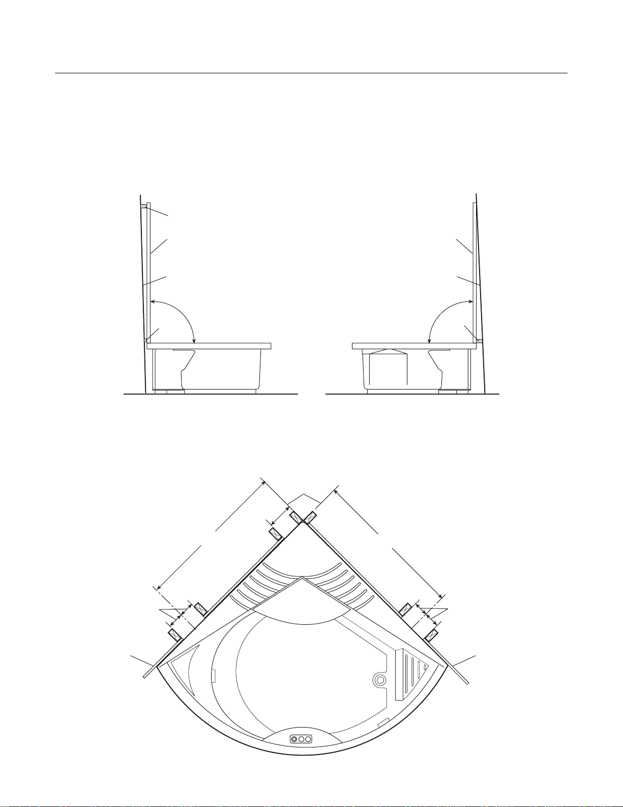
Finished Walls
Before fixing the bath in place, make sure the finished walls above the rim of the bath are perpendicular. The two wall
extrusions at the edges of the fixed panels will allow some compensation for walls out of true less than 3/16". (See
fixed panels installation for wall extrusions.) If that is the case, the bath may be placed against the finished walls. If
more than 3/16", shims will be necessary and the bath moved away from the wall an appropriate distance. When final
setting of the bath, secure the metal straps attached to the bath to the floor with screws or anchors.
SHIM
WALL EXTRUSION
FINISHED WALL
90°
SHIM
WALL EXTRUSION
FINISHED WALL
90°
SHIM
Wall Cutouts
FACE OF
FINISHED
WALL
12"
FINISHED
WALL
38"
38"
4-1/2"4-1/2"
FINISHED
WALL
6
Page 9

J-Allure
Wall Cutouts
9" MIN.
CUTOUT
IN WALL
81"
FINISHED
WALL
4" MIN.
ELECTRICAL
OUTLET (115 V)
FOR BATH
STUD FOR
PLUMBING
SEE
STUD
DETAIL 1
FINISHED
FLOOR
38"
BATH
PERIMETER
12" MIN.
7"
23-1/4"
38"
9" MIN.
75-1/2"
1x4 (NOT FOR SUPPORT)
DO NOT BRIDGE
CENTER PANEL CUTOUT
ELECTRICAL
OUTLET (230 V)
FOR CENTER PANEL
FOR UNITS WITH TV
CABLE TV OUTLET
FINISHED
WALL
Suggested Rough-in
Plumbing for Center Panel
STUD
1/2" NPTF
COLD
WATER
SUPPLY
HOT
WATER
SUPPLY
3/8 OD COPPER TUBE
TO STEAMPRO UNITS
3-1/2"
FINISHED
FLOOR
STUD DETAIL 1
2-3/4"
19-3/4"
41-1/2"
7
Page 10
J-Allure
SHELL CLIP
SKIRT
WOOD BLOCK
SCREW
WITH
HINGED
CAP
1/2"
FINISHED
FLOOR
3-1/2"
SKIRT BLADE
NOTE: SAME LEVEL
AS FINISHED FLOOR
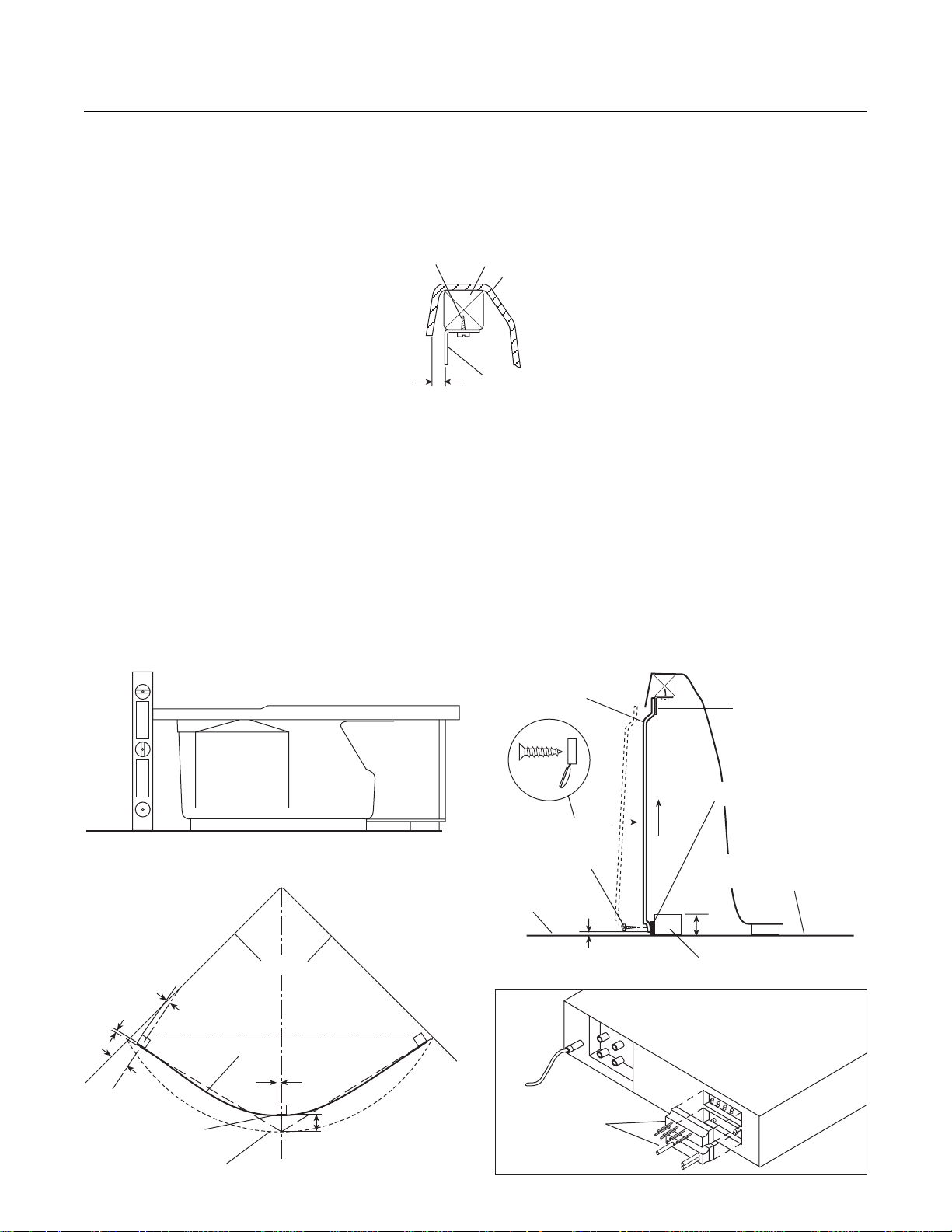
Skirt Installation
It is necessary to mount the skirt shell clips on the factory installed wood blocks located along the underside of the
rim. Mark hole locations on the blocks using clips as a template for correct hole spacing. Then drill a pilot hole 1/2"
deep using a 3/32" diameter drill. Use caution to avoid drilling through the bath rim. Secure the clips to the wooden
blocks as shown.
Using a square or level, determine the location of the vertical drop from the bath rim at both ends and the center of
the bath. Locate the center wood block (provided) at the appropriate distance from the vertical drop, centering it
lengthwise with relation to the rim of the bath. The faces of the side blocks (provided) will be oriented along a line
from the center vertical drop point to the end vertical drop point. The blocks can be screwed, nailed or adhered with
adhesive to the floor. Make sure the finished sides of blocks are outward. Glue the skirt blade (1-1/2" x 79-3/4" white
acrylic strip) to the front of the wooden blocks.
Before attaching skirt, locate the CD/radio speaker and power connectors coiled under the bath rim. Uncoil and
connect the speaker and power connectors to the CD/radio. Also locate the green ground wire and connect to the
chassis of the CD /radio.
Slip the skirt up between the rim and the shell clips. While holding the skirt at the bottom, move it inward toward the
bath. Lift it up so there is 1/2" gap between the floor and the bottom of the skirt. While using shims to hold the skirt
up, attach the skirt to the skirt blade and wooden blocks with screws through the predrilled holes.
SCREWS
(PROVIDED)
1/4"
WOOD
BLOCK
SHELL
SHELL CLIP
USING A SQUARE OR LEVEL, MARK THE
PERIMETER OF THE BATH ON TH FLOOR
7/8"
2"
FINISHED SIDE
OF BLOCK
BATH PERIMETER
1-1/2"
SKIRT BLADE
WALL
1-1/2"
SPEAKER POWER
CONNECTORS
8-5/8"
8
Page 11

J-Allure
Service Access
The skirt fits along the front of the bath and is an access panel for servicing. Allow a space of at least 8 inches away
from the bath for skirt removal. To remove the skirt, remove the screws at the bottom of the skirt and withdraw the
skirt.
Bath Electrical Connections
A separate circuit, which must be protected by a Ground Fault Circuit Interrupter (GFCI), is required. Install a duplex
outlet (not provided) to the studwall underneath the bathtub, at least 4 inches above the floor.
CAUTION: Operating the motor/pump without enough water in the bath can cause leaking and permanent
damage to the pump. Before power is applied to the installation, make sure the switch is in the OFF position
to avoid pump damage.
DANGER: RISK OF ELECTRIC SHOCK. Connect only to a circuit protected by a Ground Fault Circuit
Interrupter.
FINISHED
WALL
3 PRONG
PLUG
DUPLEX
RECEPT.*
4" MIN.
*(NOT PROVIDED)
FLOOR
FROM J-BOX
Drain Information
A drain/overflow assembly must be installed on the bath, water tested, and connected to the sanitary system of the
house. After opening the carton, inspect for damage and verify that the kit is of the proper finish. In the Jacuzzi
Whirlpool Bath drain/overflow kit, note that the waste flange, strainer, overflow cover and cover screws are packaged
in a separate package within the kit to protect the trim finish. Follow the installation instructions provided with the drain/
overflow kit.
After the drain is fully installed, test for proper drainage. If the unit does not drain properly, rectify this condition before
proceeding with the installation. Jacuzzi Whirlpool bath is not responsible for removal and/or reinstallation costs.
NOTE: Watertight installation of the drain is the installer's responsibility. Drain leakage is excluded from the
Jacuzzi Whirlpool Bath warranty of this product.
Plumbing
Pump, jets, and suction fittings for the whirlpool system are factory plumbed in schedule 40 PVC piping. All Jacuzzi
Whirlpool Bath products are factory tested for proper operation and watertight connections prior to shipping.
Before securing the bath to the floor a test for possible water leaks must be made. Fill the bath and check for leaks.
If leaks are detected, notify your Jacuzzi Whirlpool Bath Dealer. Do not install the unit.
9
Page 12

J-Allure
Water Supply
Consult local authorities for plumbing code requirements in your area.
IMPORTANT: Proper installation of the fill spout plumbing and compliance with local codes are the
responsibility of the installer. Jacuzzi Whirlpool Bath does not warrant connections of water supply fittings
and piping, fill systems, or drain/overflow systems. Nor is it responsible for damage to the bath which occurs
during installation.
CAUTION: A nonflammable protective barrier must be placed between soldering work and bath unit to prevent
damage to the bath.
Hot and Cold Supply Valve & Fill Spout Locations
SIDE WALL
APPROX.
1-1/2"
FRAME
RIGHT SIDE WALL
RECOMMENDED
BATH CONTROLS
HOT & COLD SUPPLY VALVE LOCATION
FILL SPOUT
LOCATION
RIGHT SIDE WALL
Clean-Up After Installation
To avoid dulling and scratching the surface of the bath, never use abrasive cleaners. A mild liquid detergent and warm
water will clean soiled surfaces.
Remove spilled plaster with a wood or plastic edge. Metal tools will scratch the surface. Spots left by plaster or grout
can be removed if lightly rubbed with detergent on a damp cloth or sponge.
Paint, tar, or other difficult stains can be removed with paint thinner, turpentine, or isopropyl alcohol (rubbing alcohol).
Minor scratches which do not penetrate the color finish can be removed by lightly sanding with 600-grit wet/dry
sandpaper. You can restore the glossy finish to the acrylic surface of the bath with a special compound, Meguiar's
#10 Mirror Glaze. If that is not available, use automotive rubbing compound followed by an application of automotive
paste wax.
Major scratches and gouges which penetrate the acrylic surface will require refinishing. Ask your Jacuzzi Whirlpool
Bath dealer for special instructions.
10
Page 13

J-Allure
HAND HELD SHOWER
HOLDER COVER
CENTER PANEL DOOR
Center Panel Installation
Connect the fixed male end of the flexible supply lines to the female supply connections in the wall cutout.
Position the center panel frame in the corner of the bath with the mounting tabs between the edge of the bath and wall.
To open the service door, remove the screw cover below the mixer handle and unscrew the exposed screw. To allow
the center panel door to be opened wider, it may be necessary to remove the hand held shower holder as shown below.
Open the door.
Unscrew the M6 bolt and install the two brackets. Check the plumbness with the two brackets touching the wall. If
necessary adjust the nut till the center panel is perpendicular to the shell deck.
Using the holes in the brackets as a guide, drill two 3/16" holes. Secure the frame to the wall using the wall anchors
and screws (#8x1"). Again check the plumbness and make sure the nuts are tight.
SCREW
COVER
90°
BATH RIM
WALL ANCHOR
BRACKET
NUTS
CENTER
PANEL
FRAME
MOUNTING
TAB
M6 BOLT
(2 PLACES)
11
Page 14

J-Allure
Center Panel Installation (cont.)
Connect the ends of the flexible supply lines with adaptors to the hot and cold connections of the mixer.
The steam lines are to be routed in such a way that they travel up from the steam generators and down to the steam
heads. Using cable ties, tie up the steam lines so there are no kinks or low spots that may trap water. (Do NOT operate
the steam generators without the water supply ON as permanent damage to the generators will occur.)
Connect the steam lines to the generators using hose clamps.
For units with TV, insert audio cables, cable TV lead, fan and TV power cords through the hole in drip shield.
Plug the power cord into the 230 VAC outlet installed previously as shown in the rough-in section.
DANGER: RISK OF ELECTRIC SHOCK. Connect only to a circuit protected by a Ground Fault Circuit
Interrupter.
Reinstall hand held shower holder if removed. Apply sealant to mounting holes if holder was removed completely.
HOT WATER
SUPPLY HOSE
COLD WATER
SUPPLY HOSE
MIXER
DRIP SHIELD
(MODELS WITH
TV ONLY)
FROM STEAM
FITTINGS ON BATH
230V OUTLET
POWER SUPPLY CORD
CABLE TIES
3/8" COPPER TUBING
FROM 3/8" SUPPLY FITTING
CABLE TV
FAN POWER CORD,
CABLE TV LEAD
AND AUDIO CABLES
POWER CORD FOR TV
(UNIT WITH TV SHOWN)
12
Page 15

J-Allure
TV Installation (Units with TV)
Remove drip shield. Connect power cord, audio cable antenna/cable TV. Hook up fan power lines with red to red and
black to black wires. Tighten cable tie and cut off excess. Tighten cable tie with anchor (not supplied) to the TV power
cord. It is not necessary to attach anchor to drip shield; the cable tie and anchor are used to ensure the TV power
cord remains inside drip shield. Position the drip shield over TV and secure. Close the door and make sure the sensor
hole on the door aligns with the TV sensor. If they do not align, adjust the TV position till they are aligned. Secure
the door. Reinstall hand held shower holder if removed. Apply sealant to mounting holes if holder was removed
completely.
DRIP SHIELD WIRING
DRIP SHIELD
FAN
BLACK
RED
AUDIO
CABLE
HEADPHONES
IF THE TV HAS BEEN MOVED IN SHIPPING,
LOOSEN ADJUSTMENT SCREWS AND ADJUST
THE TV SO IT IS CENTERED IN WINDOW.
CABLE TV
CABLE TIE
TV CONNECTIONS
TV POWER CORD
AUDIO CABLE
(HEADPHONE)
TO CABLE TV LINE
DC POWER INPUT
DRIP SHIELD
ADJUSTMENT
SCREWS
(4 PER DIRECTION)
LCD TV
BEZEL
POWER, AUDIO AND
CABLE TV/ANT. CABLES
13
Page 16

J-Allure
Fixed Panels Installation
Locate the guide with the gasket. This is the lower guide. Remove this gasket and install on the top guide. Position
the lower guide on the two fixed panels while they are resting on the floor in an upside down position. Align the predrilled
holes in the guide and panels and screw together with screws and spacers (3.5x45mm self-threading). Attach the
external extrusion of the panels to the guide with 4.2x19mm self-threading screws. The right and left hand fixed panels
are identified by the logo.
Invert the assembled components and install the upper guide following the same procedure as used with the lower
guide. Caulk the top of each fixed panel.
SCREWS WITH SPACERS (4)
UPPER GUIDE
SEALANT
SEALANT
LOGO
SCREWS (8)
(4.2x19mm)
SEALANT
LOWER
GUIDE
REMOVE
GASKET
14
Page 17

J-Allure
Fixed Panels Installation (cont.)
Install the two wall extrusions on the ends of the fixed panel assembly. Make sure they are flush against each fixed
panel.
Where the fixed panel assembly will rest on the bath rim, apply sealant. Position the fixed panel assembly on the bath
by inserting the pin into its seat on the lower guide. The curve of the fixed panel should match the curve of the bath.
Lift left side wall through the open doors. Insert the 3 bolts (welded on the side wall frame) into the slotted holes in
the center panel frame. Place the opposite side of the side wall against the fixed panel frame. Make sure the wall
extrusion is against the wall. Check perpendicularity with a level. Mark this wall extrusion position. Remove left side
wall and repeat the above steps for the right side wall. Remove this side wall and fixed panels assembly.
Using the 3 holes in each extrusion as a guide, drill three 15/64" holes into adjacent wall for each side. Attach the wall
extrusions to the walls with the anchors and 3.5x32mm screws. Drill three 7/64" holes into the fixed panel frame using
the wall extrusion holes as guides. Secure the panel frame to the wall extrusion with 3.5x9.5mm self-threading screws.
FIXED
PANEL
FRAME
WALL
EXTRUSION
FIXED PANEL
ASSEMBLY
FRAME OF
CENTER PANEL
SIDE
WALL
MARK
PIN
SEALANT
WALL
EXTRUSION
FIXED PANEL
ASSEMBLY
15
Page 18

J-Allure
Side Walls Installation
Lift one of the side walls through the open doors. Reach under the bath rim and pull up the speaker wires. Hook up
these wires observing the polarity as directed from the CD player manual. Then insert the 3 bolts into the slotted holes
in the center panel frame. Place the opposite side of the side wall against the wall. Make sure the side wall matches
the fixed panel. Set the side wall down onto the side of the bath so that the lower frame of the wall is inserted between
the bath and the wall. Secure the side wall to the center panel frame with lock washers and M6 nuts. With the wall
flush against the fixed panel, drill three 7/64" holes using holes in the wall frame as guides. (Be careful not to scratch
the finish.) Secure the wall using 3.5x9.5mm self-threading screws. Repeat the same procedure for the other side
wall. Close door and secure.
CENTER
PANEL
FRAME
FIXED
PANEL
FRAME
OBSERVE POLARITY
(SEE BLAUPUNKT MANUAL)
WALL
EXTRUSION
SIDE
WALL
REAR OF
SPEAKER
-+
SIDE
WALL
16
SIDE WALL
FRAME
BATH RIM
Page 19

J-Allure
Side Walls Caulking
After the side walls are installed, they must be caulked with silicone sealant (not provided). Seal the entire length at
the bottom and from the bottom to top where the side wall moulding meets the attached extrusion. Also caulk the joint
between the side wall extrusion and the fixed panel frame.
Apply the two foam tapes (provided) to side wall. The first tape will butt up against the curve of the side wall with the
second tape against the first tape. Remove the facing paper from both. Install the V seal as shown so that it covers
the joint between the foam tapes.
TWO STRIPS OF FOAM TAPE SIDE
BY SIDE FROM TOP TO BOTTOM
(ONLY ON RIGHT SIDE WALL)
WALL
V SEAL
EXTRUSION
FIXED
PANEL
FRAME
SIDE
WALL
SEALANT
SIDE WALL
SEALANT
ALONG ENTIRE
LENGTH OF
SIDE WALL
BATH RIM
SIDE
WALL
17
SEALANT
(GLASS PANELS AND GUIDES
NOT SHOWN FOR CLARITY)
Page 20

J-Allure
Inside Caulking
Caulk the joint between the lower guide and the bath.
FIXED PANELS
LOWER GUIDE
SEALANT
18
Page 21

J-Allure
Sliding Doors Installation
Take one of the doors inside the shower compartment. The upper rollers will be fixed while the bottom rollers will be
loose. In a vertical position, insert the upper and lower rollers (at the same time) into the roller insertion point located
at the center of the upper and lower guide. Slide the door toward the wall. Insert the remaining set of rollers. Making
sure the bottom rollers are positioned in the bottom guide channel, lift them up and tighten the locking nuts. Confirm
that the door slides smoothly without binding. Slide the door toward the wall and repeat the above steps for the other
door. Adjust lower and upper rollers to align doors where they meet each other when closed. Insert the four M5 stud
screws and M5 acorn nuts (door stops) into the threaded holes in the upper guide and tighten them.
ROLLER
INSERTION
POINT
ROLLER
CHANNEL
DOOR STOP
STUD SCREWS
AND ACORN NUTS
ROLLER
INSERTION
POINT
ROLLER
CHANNEL
19
Page 22

J-Allure
Dome Installation
Apply gasket to dome as shown below. Note: there is no gasket on the dome where it rests on the upper guide. Then
carefully lift the dome and place onto the corner panel , side walls and upper guide. Bring the edge of the dome in
contact with the front part of the upper guide. Note the correct position of the dome on the upper guide and side walls
as shown below.
DOME
GASKET
DOME
GASKET
SIDEWALL
DOME
GASKET
FRAME
DOME
GASKET
20
UPPER
GUIDE
Page 23

OPERATING INSTRUCTIONS
HOT
COLD
OFF
CENTER PANEL
System control is provided by the electronic display located on the center panel.
The display is used to start up the five functions of the unit: the hand held shower, the fixed shower, the hydromassage
(all jets), hydromassage (pulsed jets), and the steam bath. The display is composed of clear symbols to identify the
five functions.
STEAM
START BUTTON
R
WHIRLPOOL
HAND HELD SHOWER
FIGURE 1. CENTER PANEL AND DISPLAY
BATH
START BUTTON
Starting Any Function
The mixer control valve must be ON for the functions of
the center panel to be operational. After the mixer valve
has been set and is ON, press any button to start that
function. The steam function can be ON with any other
function. Other functions can only be ON one at a time.
Pressing the OFF button turns all functions OFF.
JETS START
BUTTON
START BUTTON
PULSED JETS
START BUTTON
OFF
OFF BUTTONSTATIONARY SHOWER
Mixer Control
To adjust the temperature turn the mixer handle as
shown in Figure 2. When exiting the J-Allure with all
functions OFF, the mixer control must be turned to the
FIGURE 2. MIXER CONTROL
OFF position.
Hand Held Shower
Pressing the Hand Held Shower button once activates hand held shower and pressing a second time deactivates the
shower. Pressing the OFF button or any other button will turn the shower mode OFF.
Stationary Shower
Pressing Stationary Shower button once activates the shower and pressing a second time deactivates the shower.
Pressing the OFF button or any other button except steam will turn the shower mode OFF.
21
Page 24

Starting the Hydromassage
The J-Allure allows you to enjoy the benefits of a real hydromassage. The hydromassage is created by the
combined action of 8 water jets (two sets of four). The action of each group of four jets is either alternated or
pulsed.
To start the hydromassage jets, press the JETS button once (Figure 1). This will activate the jets by alternating the
sets of four jets. Pressing it a second time will pulse all eight jets. Pressing a third time turns the hydromassage OFF.
While the hydromassage is in either mode, the PULSED JETS button may be pushed. Pressing this button once will
increase the rate of the pulses from a default speed. Pressing a second and third time continues to increase the rate
of pulsation. Pressing a fourth time reverts to the default rate. To stop the hydromassage in any mode, press the
OFF button or any other button.
Starting the Steam Bath
Press the STEAM start button on the display (Figure 1). The steam function has a 60 minute cycle after which it turns
off automatically. The steam bath can be turned off at any time by depressing the OFF button. Do NOT operate the
steam generators without the water supply ON as permanent damage to the generators will occur.
Note: During steam bath operation, keep legs a distance of at least 3" away from the steam jets.
BATH OPERATION
Note: These instructions pertain to all bath products manufactured by Jacuzzi Whirlpool Bath. Not all
features discussed in this instruction pamphlet apply to all baths.
All baths manufactured by Jacuzzi Whirlpool Bath are designed for "fill and drain," which means the bath should be
drained after each use and filled with fresh water by the next bather. This is a health precaution, as these baths are
not designed to hold water continuously like pools or spas. If you want a unit designed to continuously hold water,
see your Jacuzzi Whirlpool Bath dealer for the complete line of whirlpool spas available.
Once the bath is installed, remove any residue or foreign materials left over from construction. Use turpentine or paint
thinner to remove stubborn stains, paint or tar. Other dirt can be cleaned off with a mild liquid detergent on a damp
cloth. Scrape off plaster with a wooden or plastic edge; do not use metal scrapers, wire brushes or other metal
tools, as they will damage the bath's surface.
Water Level
Close the drain and fill the bath until water is at least 2" above the highest jet (see water line indicated in the illustration).
Do not turn on the whirlpool system at any time if the jets are not completely immersed in water. Running the
whirlpool system when there is insufficient water in the bath could result in water spraying outside the bath area.
Running the whirlpool system without water will damage the recirculating pump.
Magic Touch® Whirlpool Switch
The Magic Touch whirlpool ON/OFF switch, conveniently located on the bath, allows you to turn the whirlpool system
on and off while in the bath. Simply push down on the switch button to turn on the whirlpool system. To turn the system
off, push down on the button again.
If your bath has an optional Jacuzzi Whirlpool Bath wall mounted timer, set it for the amount of time you wish the
whirlpool to operate. Note: when you desire less than 10 minutes of whirlpool action, it is necessary to turn the timer
knob clockwise past the number 10 and then back to the desired amount. If the whirlpool action does not begin when
the timer is correctly set, it is necessary to push the Magic Touch switch button.
FILL TO AT LEAST 2"
ABOVE HIGHEST JET
2"
MAGIC TOUCH SWITCH
DEPRESS CENTER ON/OFF
P
L
O
R
I
O
H
W
L
22
Page 25

Controlling Whirlpool Action
DIRECTIONALLY
ADJUSTABLE
FULLY
ADJUSTABLE
JETS
The whirlpool action in your bath is influenced by three factors – direction of flow, force of water, and force of air.
All baths manufactured by Jacuzzi Whirlpool Bath are equipped with fully adjustable PowerPro® jets, which are
adjustable for all three factors. Some baths have additional directionally adjustable jets which can be adjusted for
direction and flow of air only.
Direction: To change the direction of the water flow, swivel the jet nozzle to the desired angle. The jets can be directed
individually toward any location on your body to provide a hydromassage. The jets can also be adjusted so that they
all point in the same direction (clockwise or counterclockwise) to circulate the water in a circular motion around the
bath, causing a total whirlpool effect.
Water Force: The high volume, fully adjustable jets can be adjusted to control the force of the water coming into the
bath. For robust action, increase the force of the flow by rotating the jet handles to the left (counterclockwise). For
a more gentle effect, rotate the handles to the right (clockwise). Never run the whirlpool system with all the jets
closed.
Force of Air: Two knobs located on the bath serve as controls for the air induction system. The intensity of the
hydromassage whirlpool action is determined by the amount of air inducted into the water. As the amount of air is
increased, the hydromassage action increases. For maximum air induction, rotate the control knobs fully counterclockwise to the largest circles. For fewer air bubbles, decrease the amount of air induction by rotating the control knob
clockwise. When the knobs are turned to the smallest circles, only water is being circulated.
AIR INDUCTION CONTROLS
TURN CLOCKWISE TO
REDUCE AIR FLOW
TURN COUNTER-CLOCKWISE
TO INCREASE AIR FLOW
CD/RADIO
Note: The remote for the CD/radio is not intended to be used inside the shower or in the bath.
Note: For units with AM/FM radios, the quality of AM reception will vary by locality. Jacuzzi Whirlpool Bath is not
responsible for the quality of AM reception.
NOTE: In order to hear the TV audio, the Pioneer CD Receiver AUX function must be setup to be ON.
To perform this setting:
• If the unit is on, press SOURCE and hold until the unit turns off.
• Press FUNCTION repeatedly until AUX appears in he display
• Select AUX on and off with . The status will be displayed: AUX :ON.
TV
For operation of the TV consult the manual enclosed.
Note: The remote for the TV is not intended to be used inside the shower or in the bath.
23
Page 26

CENTER PANEL MAINTENANCE
The hand held shower head is equipped with a screen
which must be occasionally cleaned of limestone and
other deposits. The screen is placed between the
flexible hose and the shower head. If limestone deposits
are on the jet nozzles, the shape of the water jets may be
altered. Remove and clean the nozzles occasionally.
Forcefully turn the nozzle counterclockwise until a click
is felt. Then remove the nozzle and clean it by soaking
it in a moderate vinegar and water solution. Do not use
metal tools (such as scissors or screwdrivers, etc.) to
clean the nozzle. For routine cleaning of plastic surfaces
use a mild liquid detergent only. Do not use abrasive
cleaners, alcohol, or other solvents. Any normal polish
can be used to keep acrylic surfaces shiny. The glass
panels can be cleaned with any glass-cleaning product
available on the market. Do not use abrasives, sol-
vents, or acetone on any part of the J-Allure.
Important (For units with TV): These units are equipped
with a fan mounted inside the TV housing. At least every
2 years have a service technician verify that the fan is
operational. If the fan is not operating properly discontinue TV use until fan can be repaired or replaced.
BATH MAINTENANCE
Cleaning the Bath
To clean your bath, simply use a mild, nonabrasive liquid
detergent solution. You can protect and restore the
gloss to a dulled acrylic surface by applying Meguiar's
#10 Mirror Glaze, a product specifically designed for use
on acrylic finishes. If Meguiar's is not available, an
acrylic polish of equal quality or automotive paste wax is
acceptable. Never use abrasive household cleaners
on any Jacuzzi Whirlpool Bath product.
Repairs to the Surface
Minor scratches which do not penetrate the color finish
can be removed by lightly sanding with 600-grit wet/dry
sandpaper. Restore the gloss using Meguiar's Mirror
Glaze or automotive paste wax.
Major scratches and gouges which penetrate the acrylic
surface will require refinishing. Ask your Jacuzzi Whirlpool Bath dealer for special instructions.
Purging the Whirlpool System
NOTE: THE WHIRLPOOL SYSTEM SHOULD BE
PURGED AT LEAST TWICE A MONTH
To remove accumulations of bath residue from the
whirlpool system, it is recommended that a whirlpool
bath be purged at least twice a month. For best results,
however, we recommend that you purge your whirlpool
bath after each use using our exclusive two-part plumbing system cleaner made specifically for whirlpool
baths. Systems Clean ™ is available through an authorized Jacuzzi Whirlpool Bath Distributor or by calling us
direct at 1-800-288-4002. Instructions for use: Immediately after bathing and exiting the whirlpool bath, leave
the bath water in the tub and add hot water, if necessary,
so the water is at least 2" above the highest jet. Turn on
the unit without the aerator. Pour the contents of the
Systems Clean Packet 1 (taking care not to get the
material on yourself) into the bath near the intake for the
circulation pump. Repeat same process with Systems
Clean Packet 2. It is important to use Packet 1 before
Packet 2 to avoid a strong odor. Run the bath for 5 to
10 minutes. Drain completely and rinse any residue.
If you have followed the standard purging instructions
above and still have an excess accumulation of bath
residue and desire an alternative cleaning mechanism,
we recommend SUPER SYSTEMS CLEAN PLUS manufactured by Stearns Packaging to rectify this condition.
This may be obtained by contacting us at l-800-288-
4002. It is recommended that you follow the instructions
provided by the manufacturer with the product. Repeated use may be necessary. SUPER SYSTEMS
CLEAN PLUS does not replace the necessity to regularly purge your whirlpool system with Systems Clean as
recommended.
(For additional information about water content, contact
us for a copy of the Jacuzzi Water Quality Primer)
Bath Additives
NOTE: DO NOT USE OIL OR OIL BASED BATH
ADDITIVES.
If you want to use any kind of bath additive, use only a
small amount of low-foaming powder or crystal substance; the whirlpool action intensifies the foaming properties of soaps.
The use of certain bath oils, bubble baths and bath
additives may increase the level of accumulations of
bath residue in the whirlpool system. If excess accumulations persist, you should discontinue use of these
products.
24
Page 27

Suction Cover/Strainer Maintenance
Clean the suction cover/strainer of hair and debris when
necessary. To do this, remove the center screw and
detach the square cover. Clean the cover by backflushing debris from the holes. Replace the suction cover
immediately after cleaning. When reinstalling, orient the
cover/strainer with the small notch at the bottom. The
gasket must be inserted into the groove of the cover/
strainer before reinstalling onto the suction fitting.
CAUTION: Keep hair a minimum of 6 inches away
from the suction fitting at all times when the whirlpool system is operating. Hair longer than shoulder
length should be secured close to the head, or a
bathing cap should be worn. Do not operate the
whirlpool system with the suction cover removed! It
is a safety device and must always be in place on the
suction fitting to minimize the potential hazard of
hair and body entrapment.
SUCTION COVER/STRAINER ASSEMBLY
COVER STRAINER
SUCTION
FITTING
SCREW
DOME CLEANING
For routine cleaning of the dome, use a mild liquid
detergent. Do not use cleaners containing abra-
sives, alcohol, ammonia or other solvents.
NOTCH
GASKET
25
Page 28

CARE AND MAINTENANCE OF STEAMPRO STEAM GENERATORS
Maintenance of the Steampros includes flushing periodically and visually inspecting for water leaks.
To drain the units:
1. Turn OFF power to the unit.
2. To gain access to the SteamPro units, open the center panel door. To do so, open the screw cover and remove
the screw. Unplug power cords from the SteamPro units and disconnect all plumbing. Remove the SteamPro units
from their mounting.
3. Flush the tanks out; the drain plug can be removed with an 8 mm hexagonal wrench. Reinstall the steam
generators. (Do NOT operate the steam generators without the water supply ON as permanent damage to
the generators will occur.)
4. Turn ON the water supply and check for leaks.
5. Close door and reinstall door bolt.
6. Turn ON power to the unit.
HOT WATER SUPPLY
COLD WATER SUPPLY
230V OUTLET
POWER SUPPLY CORD
CABLE TIES
3/8" COPPER TUBING
FROM 3/8" SUPPLY FITTING
FROM STEAM
FITTINGS
ON BATH
26
Page 29

PRODUCT SPECIFICATIONS ARE SUBJECT TO CHANGE WITHOUT NOTICE.
USE INSTALLATION INSTRUCTIONS SUPPLIED WITH PRODUCT.
Jacuzzi Whirlpool Bath has obtained applicable code (standards) listings generally available on a national basis for products of this type.
It is the responsibility of the installer/owner to determine specific local code compliance prior to installation of this product. Jacuzzi Whirlpool
Bath makes no representation or warranty regarding, and will not be responsible for any code compliance.
Jacuzzi Whirlpool Bath National Headquarters
P.O. Drawer J, Walnut Creek, CA 94596 (925) 938-7070
Service Support: Call (925) 938-7411
©1998 Jacuzzi Whirlpool Bath N115000C 12/02
Printed on Recycled Paper
Printed in the U.S.A.
Page 30

Page 31

Jacuzzi Whirlpool Bath Limited Warranty
Shower System Product
Jacuzzi Whirlpool Bath (the “Company”) offers the following express limited warranty to the original purchaser of any Jacuzzi Whirlpool Bath Shower System product
(“unit”) who purchases the product for personal or single family use (“user”). The Company will repair or replace, at its option, the unit or its equipment in accordance with
the following terms and conditions.
ONE YEAR LIMITED WARRANTY ON SHOWER SYSTEM
Our warranty on Shower System products is for one (1) year. Our warranty covers the unit and factory-installed components (e.g., pump, motor) against defects in
material or workmanship. Warranty coverage begins on the date the unit was originally purchased by the user.
NINETY DAY (PARTS ONLY) LIMITED WARRANTY ON OPTIONS AND ACCESSORIES
Our warranty on options and accessories manufactured by the Company is for ninety (90) days for parts only. Our warranty covers options and accessories manufactured
by the Company (e.g., fill spout kits, trim kits, skirts) against defects of material or workmanship. Warranty coverage begins on the date the option or accessory was originally
purchased by the user.
Our warranty does not cover defects, damage, or failure caused by the common carrier, installer, user, or other person, or resulting from, without limitation, any of the
following: careless handling (lifting unit by plumbing, abrading finish, etc.); modification of any type for any reason (including modification to meet local codes); improper
installation (including installation not in accordance with instructions and specifications provided with the unit); connections supplied by the installer of the equipment;
improper voltage supply or unauthorized electrical modification; misuse; incorrect operation, or lack of proper routine maintenance; operation of the unit without specified
minimum amount of water or at inappropriate water temperature; use of abrasive or improper cleaners; or acts of God, such as lightning, floods, earthquakes, etc.
In addition, THE COMPANY WILL NOT BE RESPONSIBLE FOR INCIDENTAL OR CONSEQUENTIAL DAMAGES or losses arising from any cause (e.g., water
damage to carpet, ceiling, loss of use, etc.) including its own negligence; damages to, respecting, or resulting from: plated parts when chemicals are used in the unit; optional
equipment not manufactured by the Company, supplied by Dealer, installer or the Company; the unit's prior usage as an operational display; or defects that should have been
discovered before installation. This limited warranty does not include: labor, transportation, or other costs incurred in the removal and/or reinstallation of the original unit
and/or installation of a replacement unit; any costs relating to obtaining access for repair; or loss of use damage, including loss of sales, profit or business advantage of any
kind under any circumstances. Units in commercial use are excluded from any warranty coverage whatsoever.
Warranty coverage is provided in the United States of America only.
All implied warranties of merchantability and fitness for a particular purpose are equal in duration with the express warranties set forth herein.
NOTICE: This warranty gives you specific legal rights, and you may also have other rights which vary from state to state. There are no warranties applicable to Jacuzzi
Whirlpool Bath products except as expressly stated herein or as implied by applicable state and federal laws. The Company will not be responsible for any statements or
representations made in any form that go beyond, are broader than or are inconsistent with any authorized literature or specifications furnished by the Company.
Some states do not allow limitations on how long an implied warranty lasts, or the exclusion or limitation of incidental or consequential damages, so the above limitations
and exclusions may not apply to you.
WARRANTY COVERAGE
WARRANTY LIMITATIONS
IMPLIED WARRANTIES
The attached pre-addressed Warranty Registration Card MUST be filled out by the purchaser within thirty (30) days from purchase and mailed to Jacuzzi Whirlpool Bath
in order for this warranty to become effective.
RETURN OF WARRANTY CARD
Jacuzzi Whirlpool Bath
P.O. Drawer J
Walnut Creek, CA 94596-9885
Page 32

WHIRLPOOL
BATH
R
RESPONSIBILITIES OF OTHERS
Inspecting the unit prior to installation is the responsibility of the installer or building contractor who acts on behalf of the user. They are responsible for ensuring the
unit is free of defect or damage. Notices are placed on and in the unit and on the shipping carton advising the installer of this responsibility. In the event of a problem, the
unit must not be installed. The Company is not responsible for failures or damage that could have been discovered, repaired, or avoided by proper inspection and testing prior
to installation.
Damage occurring in transit is the responsibility of the carrier. The user or installer MUST open the crates and inspect the unit for damage when it is delivered. If damage
is discovered, it must be reported immediately to the seller and the carrier in writing, and an inspection requested. Failure of the carrier to respond should be reported to the
seller and the carrier. Your freight claims should be filed promptly thereafter.
It is the responsibility of the installer, building contractor, or user to provide access for service. The Company is not responsible for any costs relating to obtaining access
for repair. The user shall bear such costs and, if appropriate, must seek recovery from the installer.
Damage occurring to the unit during installation is the responsibility of the installer and/or building contractor and damage occurring thereafter is the responsibility of
the user.
Failure of any optional equipment is the sole responsibility of the equipment manufacturer. (Options and accessories manufactured by the Company are warranted for
ninety (90) days from the original date of purchase for parts only.)
The Distributor or Dealer is responsible for knowing local code requirements and notifying the installing contractor and/or user of these requirements at the time of
purchase. The Company is not responsible for costs to modify any product to obtain any code approval, such as city, county, or state building codes.
WARRANTY SERVICE
For the customer's benefit, the Company maintains a list of independent service personnel to perform required warranty service repairs. Such firms are not agents or
representatives of the Company and cannot bind the Company by words or conduct.
The Company will provide the warranty service described above when the following conditions have been met: the failure is of the nature or type covered by the warranty;
the user has informed an Authorized Jacuzzi Whirlpool Bath Service Agent or Warranty Service Department Representative of the nature of the problem during the warranty
period; conclusive evidence (e.g., proof of purchase or installation) is provided to the foregoing by the user proving that the failure occurred or was discovered within the
warranty period; an authorized independent service person or Company representative has been permitted to inspect the unit during regular business hours within a reasonable
time after the problem was reported by the user.
In order to obtain warranty service, consult your local telephone book for the location of the nearest Jacuzzi Whirlpool Bath Authorized Service Agent. Describe the
problem and the Authorized Service Agent will inspect the unit and provide the required warranty service.
If you are unable to contact a Jacuzzi Whirlpool Bath Authorized Service Agent, call or write:
Jacuzzi Whirlpool Bath
Warranty Service Department
P.O. Drawer J
Walnut Creek, California 94596
Call: (800) 288-4002
To obtain warranty replacement for factory-installed components or Company supplied options and accessories manufactured and supplied by the Company, call or write
the above. Provide a description of the problem and proof of purchase. You will be instructed how to obtain replacements and where to return, at your expense, the failed
component(s), option(s), or accessories.
All replacement parts, equipment, and repairs shall assume the remaining warranty period of the part(s) replaced.
The Company's warranty obligation shall be discharged upon tender of replacement or repair. The customer's refusal to accept the tender terminates the Company's
warranty obligation.
Limited Warranty
Accessory(ies)
Ninety-Day
Parts Only
On
Limited Warranty
Accessory(ies)
Ninety-Day
Parts Only
On
11. Was your purchase process?
12. How technically aware were you of the patented Jacuzzi
( ) $40,000 to $49,999 ( ) $150,000 and Above
( ) Very easy ( ) Easy ( ) Difficult ( ) Very difficult
your purchase?
( ) Not aware ( ) Somewhat aware ( ) Very aware
® jet system prior to
10. Approximately how long have you lived in this home? _________________
( ) 1 month-2months
Please indicate, approximately, the total annual income of your household.
( ) Up to $24,999 ( ) $50,000 to $74,999
( ) $25,000 to $29,999 ( ) $75,000 to $99,999
( ) $30,000 to $39,999 ( ) $100,000 to $149,999
9. How long did you shop before purchasing unit?
( ) Eljer ( ) Lasco ( ) Price Pfister ( ) Aqua Glass
( ) Kohler ( ) American Standard ( ) Sterling
( ) Other (Specify) ___________________________________________
( ) 1 day ( ) 2 months-6 months
( ) 2-7 days ( ) 6 months-1year
( ) 1 week-2 weeks ( ) 1 year-2 years
( ) 2 weeks-4 weeks ( ) +2 years
7. What is the age of the head of the household? _________________ years
8. What other manufacturers did you consider?
©1998 Jacuzzi Whirlpool Bath N115000C 12/02
6. What is the current market value of this property?
( ) Self/Spouse when remodeling
( ) Other ___________________________________________________
Please estimate $ _____________________________________________
( ) Self ( ) Spouse ( ) Self and Spouse Together
( ) Other Family Member ( ) Designer/Architect
( ) Builder/Plumber/Remodeler ( ) Already Installed
( ) Contractor/Plumber when remodeling
4. Who finally decided which product you would buy?
5. Who installed? ( ) Already installed/New Home
3. What was the main reason for purchase?
( ) Styling ( ) Warranty Service ( ) Product Features
( ) Brand Name ( ) Price ( ) Hydrotherapy
( ) Home Resale _____________________________________________
( ) Other ___________________________________________________
2. Who first gave you specific information about this product (specifications,
( ) Word of Mouth . . . Friend/Relative/Acquaintance
( ) Other . . . Please Describe __________________________________
prices, etc.)?
( ) Dealer/Plumbing Supplier ( ) Builder ( ) Remodeler
( ) Plumbing Contractor ( ) Retailer/Home Center Store
( ) Decorator/Architect ( ) Already Installed
This card must be filled out and returned to the address printed on the
other side within thirty (30) days from date of purchase in order for this
warranty to be come effective.
Purchaser's Name ______________________________________
Purchaser's Address ____________________________________
City _________________ State _____ Zip _______
Date of Purchase ______________________________________
Model Name __________________________________________
Serial Number ________________________________________
Dealer's Name ________________________________________
Dealer's Address _______________________________________
1. How did you first hear about this Jacuzzi
( ) Advertisement ( ) Article in Magazine/Newspaper
( ) Visited Dealer/Plumbing Supplier ( ) Yellow Pages
( ) Builder/Plumber/Remodeler ( ) Decorator/Architect
( ) Visited Retailer/Home Center Store
®
product?
Warranty
Registration Card
N115000C
 Loading...