

Page 1
OWNER’S MANUAL
J-300
™
Collection
J - 315
J - 325
J - 335
J - 345
J - 355
J - 365
J - 375
J - 385
2530-398A Rev. A
Page 2

Attention New Spa Owner!
Congratulations on the purchase of your new Jacuzzi® spa! The following is a
list of automated functions performed by your spa. These functions are listed
below in an attempt to alleviate any operational concerns you may have during
the rst 24 hours of ownership! Also listed below are important maintenance
recommendations you should observe on a regular basis to protect your new
investment.
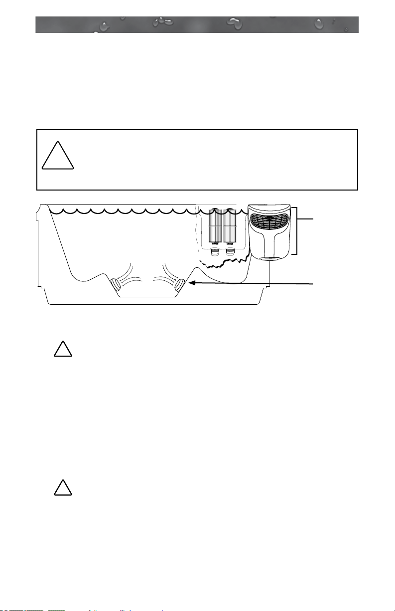
Automated Operations
Approximately two minutes after power is applied to the spa, the rst ltration/
heating cycle turns on pump 1. An automatic “blow-out” function also activates
pump 2 (if equipped) for a period of one minute to ush all lines. Then, after one
minute, pump 2 turns off and pump 1 continues to operate for the duration of the
cycle.
Note: This function only occurs during the rst ltration/heating cycle each day.
Maintain Healthy Spa Water
Always maintain your spa’s water chemistry within the following parameters:
With CLEARRAY® Without CLEARRAY®
pH 7.4-7.6 7.4-7.6
Free Chlorine no less than 1.0 ppm 3.0-4.0 ppm
Free Bromine no less than 2.0 ppm 2.0-4.0 ppm
Total Alkalinity 100-120 ppm 100-120 ppm
Calcium Hardness 150-250 ppm 150-250 ppm
IMPORTANT: CLEARRAY ® Water Purication System is factory installed. If
the CLEARRAY® system is altered or is not operating efciently then follow
the “without CLEARRAY®” water chemistry parameters as dened by the
Association of Pool and Spa Professionals. CLEARRAY® requires an annual
bulb replacement to properly sanitize your water.
!
TO DECREASE RISK OF INFECTION OR DISEASE! Always maintain
your spas lter as outlined below to ensure healthy spa water. Refer page 43
“Water Quality Maintenance” for additional information.
Required Filter Maintenance
Your new spa is equipped with an advanced water ltration system that provides
unsurpassed water quality! To ensure maximum water quality at all times, you
should clean both lter cartridges every month, or earlier as necessary. See page
36 for detailed lter cartridge cleaning/replacement instructions.
Required Water Replacement
!
TO DECREASE RISK OF INFECTION OR DISEASE!
the spa’s water every 3 months. The frequency depends on a number of variables
including frequency of use, number of users, and attention paid to water quality
maintenance. You will know it is time for a change when you cannot control
sudsing and/or you can no longer get
even though the key water balance measurements are all within the proper
parameters. See page 43 for additional information.
©Jacuzzi Hot Tubs. All Rights Reserved
the normal feel or sparkle to the water,
You should replace
Page 3

J-300
Table of Contents
1.0 Important Spa Owner Information.....................................1
2.0 FCC Notice ..........................................................................1
3.0 Important Safety Instructions for all Spa Owners ...........2
3.1 Entrapment Risk ...................................................................6
3.2 Hyperthermia ........................................................................7
3.3 Important Additional CSA Safety Instructions
(Canada Only) ......................................................................8
3.4 General Electrical Safety Instructions ...................................8
4.0 Choosing A Location ..........................................................9
4.1 Outdoor Location ................................................................10
4.2 Indoor Location ...................................................................10
5.0 General Electrical Safety Instructions ............................ 11
6.0 Power Requirements ........................................................12
7.0 Electrical Wiring Instructions ..........................................15
8.0 Spa Fill Up Procedure ......................................................18
9.0 Control Functions .............................................................23
9.1 Control Panel ......................................................................23
9.2 General Spa Features And Controls ...................................24
10.0 Operating Instructions .....................................................25
10.1 Setting Water Temperature ................................................25
10.2 Activate Jet Pumps .............................................................26
10.3 Light On/Off Button .............................................................26
10.4 Light Mode Button...............................................................26
10.5 Jets .....................................................................................26
10.6 Selecting Desired Massage Action .....................................27
10.7 Waterfall Feature ................................................................27
10.8 Air Controls .........................................................................27
10.9 Optional BLUEWAVE™ Spa Stereo System ......................27
11.0 Menu Features and Programming Instructions .............28
11.1 Primary Filtration Menu.......................................................29
11.2 Programming the Primary Filtration Cycle ..........................30
11.3 Programming the Change Filter Timer ...............................31
11.4 Secondary Filtration Menu ..................................................32
11.5 Programming the Secondary Filtration Cycle .....................32
11.6 Programming the CLEARRAY Bulb Replacement Timer ...33
11.7 Economy Menu ...................................................................33
11.8 Programming the Economy Mode ......................................34
Page 4

J-300
11.9 Lock Menu ..........................................................................34
11.10 Programming the Lock Modes ............................................35
11.11 Top Menu Lock ...................................................................35
11.12 Programming the Top Menu Lock Feature .........................35
12.0 Spa Maintenance ..............................................................36
12.1 Cleaning The Filters............................................................36
12.2 DrainingandRelling..........................................................39
12.3 Pillow Care..........................................................................40
12.4 Cleaning The Spa Interior ...................................................40
12.5 Vinyl Cover Care and Maintenance ....................................40
12.6 Tool Free Access Door .......................................................41
12.7 Maintaining The Synthetic Cabinet .....................................41
12.8 Winterizing ..........................................................................42
12.9 Restarting Your Spa in Cold Weather .................................43
13.0 Water Quality Maintenance ..............................................43
13.1 pH Control...........................................................................44
13.2 Sanitizing ............................................................................44
13.3 CLEARRAY®(Ultraviolet)WaterPuricationSystem ........45
13.4 CLEARRAY® Bulb Replacement and Quartz Tube
Maintenance .......................................................................46
14.0 Error Conditions/Error Messages ...................................49
14.1 Summer Logic.....................................................................49
14.2 Panel Displays COL ............................................................49
14.3 Panel Displays ICE .............................................................49
14.4 Panel Displays SN1 ............................................................49
14.5 Panel Displays SN2 ............................................................49
14.6 Panel Displays BLB ............................................................49
14.7 Panel Flashes FL1 or FL2 ..................................................50
14.8 Panel Displays OH..............................................................50
14.9 Panel Displays (- - -) ...........................................................50
14.10 Panel Displays CF ..............................................................51
15.0 Troubleshooting Procedures ...........................................51
15.1 None of the Components Operate (e.g. Pump, Light) ........51
15.2 Pump Does Not Operate ....................................................51
15.3 Poor Jet Action ...................................................................52
15.4 Water is Too Hot .................................................................52
15.5 No Heat...............................................................................52
Page 5

J-300
16.0 Circuit Board Diagrams....................................................53
16.1 North American J-335, J-345, J-355, J-365,
J-375 and J-385 Dedicated Power Models (60 Hz) ............53
16.2 North American J-315 and J-325 Convertible
Power Models (60 Hz) ........................................................54
16.3 Export J-335, J-345, J-355, J-365, J-375 and
J-385 Models (50 Hz) .........................................................55
16.4 Export J-315 and J-325 Models (50 Hz) .............................56
17.0 Optional BLUEWAVE™ Spa Stereo System ...................57
17.1 Pairing the Remote and Stereo ..........................................58
17.2 Audio Settings.....................................................................58
17.3 Wireless Remote Control Functions ...................................60
17.4 Electronic Device Connections and Functions ...................61
17.5 Wireless Remote Battery Replacement Procedure ............64
17.6 BLUEWAVE™SpaStereoSystemSpecications .............64
17.7 Stereo Cautions ..................................................................65
Page 6

J-300
Page 7

J-300
1.0 Important Spa Owner Information
Your Jacuzzi J-300 Collection spa is constructed to the highest standards
and is capable of providing many years of trouble-free use. However,
because heat retentive materials are utilized to insulate the spa for
efcient operation, an uncovered spa surface and wall ttings directly
exposed to sunlight and high temperatures for an extended period are
subject to permanent damage. Damage caused by exposing the spa
to this abuse is not covered under warranty. We recommend that you
always keep the spa full of water when it is exposed to direct sunlight
and that you keep the Jacuzzi premium insulating cover in place at
all times when the spa is not in use. Read and carefully follow the
requirements for your spa’s support base found in Section 4.0 titled,
“Choosing A Location” (page 9).
Jacuzzi constantly strives to offer the nest spas available,
therefore modications and enhancements may be made which
affect the specications, illustrations and/or instructions contained
herein.
2.0 FCC Notice
This equipment has been tested and found to comply with the limits for
a Class B Digital Device, pursuant to Part 15 of the FCC Rules. These
limits are designed to provide reasonable protection against harmful
interference in a residential installation. This equipment generates, uses
and can radiate radio frequency energy and, if not installed and used in
accordance with the instructions, may cause harmful interference to radio
communications. However, there is no guarantee that interference will
not occur in a particular installation. If this equipment does cause harmful
interference to radio or television reception, which can be determined by
turning the equipment off and on, the user is encouraged to try to correct
the interference by one or more of the following measures:
1. Rearrange or relocate the receiving antenna.
2. Increase the separation between the equipment and receiver.
3. Connect the equipment into an outlet on a circuit different from the
circuit connected.
4. Consult the dealer or an experienced radio/TV technician for help.
Changes or modications not expressly approved by the party
responsible for FCC compliance could void the user’s authority to
operate this equipment.
1
Page 8

J-300
3.0 Important Safety Instructions for all Spa Owners
READ AND FOLLOW ALL INSTRUCTIONS CAREFULLY!
This spa was manufactured to meet the standards and specications
outlined in the “Virginia Graeme Baker Pool and Spa Safety Act” (VGB
Safety Act). When installing and using this spa, basic safety precautions
should always be followed, including:
!
1.
• Extreme caution must be exercised to prevent unauthorized access
• To avoid accidents, ensure that children do not use this spa unless
• Use the straps and clip tie downs to secure the spa cover when not
• There is no representation that the cover, clip tie-downs, or actual
2.
• Keep hair, loose articles of clothing or hanging jewelry away from
• Never use the spa unless all suction guards, lter, lter lid, or
• Never operate or use the spa if the lter, lter lid, or skimmer
• The suction ttings and suction covers in this spa are sized to match
• Never replace a suction tting or suction cover with one rated less
DANGER: RISK OF SEVERE INJURY OR DROWNING!
by children.
supervised at all times. Adult supervision is a critical safety factor in
preventing children from drowning.
in use. This will help discourage unsupervised children from entering
the spa. Keep the spa cover secure in high-wind conditions.
locks will prevent access to the spa.
!
DANGER: RISK OF SEVERE INJURY OR DROWNING!
suction ttings, rotating jets or other moving components to avoid
entrapment that could lead to drowning or severe injury.
skimmer assembly are installed to prevent body and/or hair
entrapment.
assembly are broken or any part of the skimmer assembly is missing.
Please contact your dealer or nearest service center for service.
the specic water ow created by the pump(s). If it is necessary to
replace the suction ttings, suction covers or pump(s), be sure that
the ow rates are compatible and are in compliance with the VGB
Safety Act.
than the ow rate marked on the original suction tting. Using
improper suction ttings or suction covers can create a body or hair
suction entrapment hazard that may lead to drowning or severe
injury.
!
3.
DANGER: RISK OF SEVERE INJURY FROM ELECTRIC
SHOCK OR DEATH FROM ELECTROCUTION!
• Install the spa at least 5 feet (1.5m), from all metal surfaces. As an
alternative, a spa may be installed within 5 feet of metal surfaces
if each metal surface is permanently connected (bonded) by a
minimum No. 8 AWG (8.4 mm²) solid copper conductor attached
to the wire connector on the grounding lug, inside the equipment
compartment on the equipment box.
2
Page 9

J-300
• A grounding wire connector is provided on this unit to connect a
minimum No. 8 AWG (8.4 mm²) solid copper conductor between
this unit and any metal equipment, metal enclosures of electrical
equipment, metal water pipe, or conduit within 5 feet (1.5m) of the
unit.
• Never permit any electrical appliance, such as a light, telephone,
radio, television, etc. within 5 feet (1.5m) of a spa unless such
appliances are built-in by the manufacturer.
• Never bring any electrical appliances into or near the spa.
• Never operate any electrical appliances from inside the spa or when
you are wet.
• The electrical supply for this product must include a suitably rated
switch or circuit breaker to open all ungrounded supply conductors
to comply with section 422-20 of the National Electrical Code/USA,
ANSI/NFPA 70. The disconnecting means must be readily accessible
and visible to the spa occupant but installed at least 5 feet (1.5m),
from the spa.
• The electrical circuit supplied for the hot tub must include a suitable
ground fault circuit interrupter (GFCI) as required by NEC Article
680-42.
!
4.
• Extreme caution must be exercised to prevent diving or jumping
• Never stand, walk or sit on the top railing of the spa.
WARNING: RISK OF SEVERE INJURY OR DEATH!
into the spa or slipping and falling, which could result in
unconsciousness, drowning, or serious injury. Remember that wet
surfaces can be very slippery.
!
5.
• Water temperature in excess of 104°F (40°C) may be injurious to
• Refer to Section 3.2 Hyperthermia for specic causes and symptoms
• The water in the spa should never exceed 104°F (40°C). Water
• Lower water temperatures are recommended for young children
• The Consumer Products Safety Commission/USA has stated that the
• Always test the spa water temperature before entering the spa.
WARNING: RISK OF HYPERTHERMIA (OVER-HEATING)
CAUSING SEVERE INJURY, BURNS, WELTS OR DEATH!
your health.
of this condition.
temperatures between 100°F (38°C) and 104°F (40°C) are
considered safe for a healthy adult.
(children are especially sensitive to hot water) and when spa use
may exceed 10 minutes.
water temperature in a spa should not exceed 104°F (40°C).
The user should measure the water temperature with an accurate
thermometer since the tolerance of water temperature-regulating
devices may vary as much as +/- 5°F (2°C).
3
Page 10

J-300
!
6.
• Since excessive water temperatures have a high potential for
• Pregnant or possibly pregnant women should limit spa water
• Persons suffering from obesity or a medical history of heart disease,
• If you experience breathing difculties in association with using or
• Persons using medication should consult a physician before using
• Persons suffering from any condition requiring medical treatment, the
• The use of alcohol, drugs, or medication before or during spa use
7.
• Prolonged immersion in a spa may be injurious to your health.
• Observe a reasonable time limit when using the spa. Exposures
• Never use a spa immediately following strenuous exercise. Enter
WARNING: RISK OF SEVERE INJURY OR DEATH!
causing fetal damage during the early months of pregnancy, if
pregnant or possibly pregnant, consult your physician before using a
spa.
temperatures to 100°F (38°C).
low or high blood pressure, circulatory system problems, diabetes,
infectious diseases or immune deciency syndromes should consult
a physician before using a spa.
operating your spa, discontinue use and consult your physician.
a spa since some medication may induce drowsiness, while other
medication may affect heart rate, blood pressure, and circulation.
elderly, or infants should consult with a physician before using a spa.
may lead to unconsciousness with the possibility of drowning.
!
WARNING: RISK OF SEVERE INJURY OR DEATH!
at higher temperatures can cause high body temperature (overheating). Symptoms may include dizziness, nausea, fainting,
drowsiness, and reduced awareness. These effects could possibly
result in drowning or serious injury.
and exit the spa slowly. Wet surfaces can be slippery.
!
8.
WARNING: TO DECREASE RISK OF INFECTION OR DIS-
EASE!
• To reduce the risk of contracting a waterborne
tion, bacteria or virus) and/or respiratory ailments
chemistry within the parameters listed on the inside cover of this
manual and consult with a licensed engineer regarding proper ventilation if installed indoors or in an enclosed area.
• People with infectious diseases should not use a spa to avoid water
contamination, which could result in spreading infections to others.
• Always shower before and after using your spa. Maintain water
chemistry in accordance with manufacturer’s instructions. Failure to
do so may result in contracting a waterborne
bacteria or virus).
illness (e.g. an infec-
, maintain water
illness (e.g. an infection,
4
Page 11

J-300
!
9.
10. CAUTION: TO DECREASE RISK OF PRODUCT DAMAGE.
• Maintain water chemistry in accordance with manufacturer’s
• Proper chemical maintenance of spa water is necessary to maintain
11.
12. NOTE: This spa is not intended nor designed to be used in a
WARNING: In addition to maintenance of lters and water
chemistry, proper ventilation is recommended to reduce the risk of
contracting a waterborne
and/or respiratory ailments
Consult a licensed architect or building contractor to determine your
specic needs if installing your hot tub indoors.
instructions.
safe water and prevent possible damage to spa components.
!
WARNING: RISK OF SEVERE INJURY OR DEATH! The
appliance is not intended for use by persons (including children)
with reduced physical, sensory or mental capabilities, or lack of
experience or knowledge, unless they have been given supervision
or instruction concerning use of the appliance by a person
responsible for their safety.
commercial or public application. The spa buyer shall determine
whether there are any code restrictions on the use or installation
of this spa since local code requirements vary from one locality to
another.
illness (e.g. an infection, bacteria or virus)
that could be present in the air or water.
Hot Tub Safety Literature
To ensure you have a safe and enjoyable hot tub experience,
learn all you can about hot tub safety and emergency procedures.
Especially useful are the brochures listed below:
• Children Aren’t Waterproof
• Pool and Spa Emergency Procedures For Infants and
Children
• Layers of Protection
• The Sensible Way to Enjoy Your Spa or Hot Tub
The Association of Pool and Spa Professionals publishes these
brochures. To acquire a brochure:
• Ask your hot tub dealer (they may have copies)
• Go to http://apsp.org
• Conduct your own search on the internet
• Write to the following address:
The Association of Pool and Spa Professionals
2111 Eisenhower Avenue
Alexandria VA 22314
703.838.0083
5
Page 12
J-300
3.1 Entrapment Risk
The Consumer Products Safety Commission/USA has reported that
users of pools and spas have become entrapped (stuck) to drain and/or
suction ttings causing death, drowning, or serious injury (see diagram
below). This spa was manufactured to meet the standards and specications outlined in the “Virginia Graeme Baker Pool and Spa Safety Act”
(VGB Safety Act). Entrapment risk can be minimized if proper precau-
tions are taken.
DANGER: RISK OF PERSONAL INJURY OR DEATH!
Never operate the spa if a suction tting, suction cover, lter,
!
lter lid or skimmer assembly are broken, damaged or miss-
ing.
Filter, Filter Lid,
Skimmer As-
sembly (location
and style vary by
models)
Suction Fittings,
Suction Covers
(locations vary
by models)
Note: Suction covers must be replaced every 5 years.
!
1.
DANGER: RISK OF SEVERE INJURY OR DROWNING!
Hair entrapment: May occur if hair is entangled, knotted or snagged
in a drain suction or skimmer assembly. This has been reported in
persons who when submerge themselves underwater, allowing hair
to come close and/or within the reach of the suction fittings, suction
covers or skimmer assembly.
• Keep hair away from suction ttings, suction covers, lter, lter lid or
skimmer assembly.
• Children are at risk for hair entrapment if swimming under water.
• Never allow children to play or get near the suction ttings, suction
covers, lter, lter lid or skimmer assembly.
!
2.
DANGER: RISK OF SEVERE INJURY OR DROWNING!
Limb entrapment: May occur when a limb becomes entrapped,
inserted or sucked into a suction or outlet opening.
• Always keep suction ttings, suction covers, lter, lter lid or skimmer
assembly in place when operating to avoid limb entrapment.
• Never allow children to play or get near the suction ttings, suction
covers, lter, lter lid or skimmer assembly.
6
Page 13
J-300
!
3.
Body entrapment: May occur when part of the torso becomes
• Never allow children to play or get near the suction ttings, suction
4.
Evisceration (disembowelment) entrapment: May occur when the
• Never sit on suction ttings, suction covers, lter, lter lid or skimmer
• Never allow children to play or get near the suction ttings, suction
5.
Mechanical entrapment: May occur when jewelry, swimsuit, or
• Never allow your jewelry, swimsuit, or hair accessories to come close
• Never allow children to play or get near the suction ttings, suction
DANGER: RISK OF SEVERE INJURY OR DROWNING!
entrapped, inserted or sucked into a suction or outlet opening.
covers, lter, lter lid or skimmer assembly.
!
DANGER: RISK OF SEVERE INJURY OR DROWNING!
buttocks becomes entrapped, inserted or sucked into a suction or
outlet opening.
assembly.
covers, lter, lter lid or skimmer assembly.
!
DANGER: RISK OF SEVERE INJURY OR DROWNING!
hair accessories become entangled, knotted or snagged in a drain
suction or skimmer assembly.
to the suction ttings, suction covers or skimmer assembly.
covers, lter, lter lid or skimmer assembly.
3.2 Hyperthermia
Prolonged immersion in hot water may induce hyperthermia (overheating). The use of alcohol or drugs can greatly increase the risk of fatal
hyperthermia in spas. A description of the causes, symptoms, and effects
of hyperthermia are as follows:
Hyperthermia occurs when the internal temperature of the body reaches
a level several degrees above the normal body temperature of 98.6°F
(37°C). The symptoms of hyperthermia include drowsiness, lethargy
(fatigue), and an increase in the internal temperature of the body (feeling
of being too hot). The effects of hyperthermia include:
• Unawareness of impending hazard;
• Failure to perceive heat;
• Failure to recognize the need to exit spa;
• Physical inability to exit spa;
• Fetal damage in pregnant women; and
• Unconsciousness and DANGER of drowning.
A Warning Sign is provided in your warranty packet. Please install at
a location near your spa, where it is visible to users of the spa. For
additional or replacement Warning Signs please contact your local
Jacuzzi dealer and reference item number #6530-082.
7
Page 14

J-300
3.3 Important Additional CSA Safety Instructions (Canada Only)
When using this electrical equipment, basic safety precautions should
always be followed, including the following:
1. READ AND FOLLOW ALL INSTRUCTIONS.
2. A green colored terminal or a terminal marked G, Gr, Ground,
Grounding or the symbol* is located inside the supply terminal box
or compartment. To reduce the risk of electric shock, this terminal
must be connected to the grounding means provided in the electric
supply service panel with a continuous copper wire equivalent in size
to the circuit conductors that supply this equipment (*IEC Publication
417, Symbol 5019).
3. At least two lugs marked “Bonding Lugs” are provided on the
external surface or on the inside of the supply terminal box/
compartment. To reduce the risk of electric shock, connect the local
common bonding grid in the area of the spa to these terminals with
an insulated or bare copper conductor not smaller than No. 6 AWG
(10 mm²).
4. All eld installed metal components such as rails, ladders, drains or
other similar hardware within 10 feet (3m) of the spa shall be bonded
to the equipment grounding buss with copper conductors not smaller
than No. 6 AWG (10 mm2).
5. SAVE THESE INSTRUCTIONS.
3.4 General Electrical Safety Instructions
Your new Jacuzzi spa is equipped with a “state-of-the-art” equipment
system. It contains the most advanced safety and self-protective
equipment in the industry. Nonetheless, this spa must be installed
properly to ensure dependable usage. Please contact your local Jacuzzi
dealer or local building department should you have any questions
regarding your installation.
Proper grounding is extremely important. Jacuzzi spas are equipped with
a current collector system. A pressure wire connector is provided on the
surface of the control box, located outside the equipment door (Figure
B, page 17) to permit connection of a bonding wire between this point
and any ground metal equipment, metal water pipe or conduit within 5
feet (1.5m) of the spa, or copper clad grounding rod buried within 5 feet
(1.5m) of the spa. Bonding wire must be at least No. 8 AWG (8.4 mm²)
solid copper wire. This is a most important safety assurance feature.
Before installing your spa, check with your local building department to
insure installation conforms to local building codes.
8
Page 15
4.0 Choosing A Location
IMPORTANT: Because of the combined weight of the spa, water
and users, it is extremely important that the base upon which the
spa rests be smooth, at, level and capable of uniformly supporting
this weight, without shifting or settling, for the entire time the spa is
in place. If the spa is placed on a surface which does not meet these
requirements, damage to the skirt and/or the spa shell may result.
Damage caused by improper support is not covered under warranty.
It is the responsibility of the spa owner to assure the integrity of the
support over time. We recommend a poured, reinforced concrete
slab with a minimum thickness of 4 inches (10 cm). Wood deck-
ing is also acceptable provided it is constructed so that it meets the
requirements outlined above.
J-300
WARNING:
or other platforms not specically tied into main struc-
!
tural support, consult a professional Structural Engineer
with experience in this type of application.
The spa must be installed in such a manner as to provide drainage away
from it. Placing the spa in a depression without provisions for proper
drainage could allow rain, overow and other casual water to ood the
equipment and create a wet condition in which it would sit in. For spas
which will be recessed into a oor or deck, install so as to permit access
to the equipment, either from above or below, for servicing. Make certain
that there are no obstructions which would prevent removal of all side
cabinet side panels and access to the jet components, especially on the
side with the equipment bay.
CAUTION: If the spa is indoors or located in an enclosed area,
!
proper ventilation should be discussed with an Engineer or authority
competent enough to understand the necessary provisions needed
to vent moist or heated air and air associated with chemical odors
outdoors. When the spa is in use considerable amounts of
moisture will escape potentially causing mold and mildew. This
can cause health risk. Over time, this can damage certain surfaces,
surroundings, and equipment.
For spas that are to rest on balconies, roofs
9
Page 16

J-300
4.1 Outdoor Location
In selecting the ideal outdoor location for your spa, we suggest that you
take into consideration:
• The proximity to changing area and shelter (especially in colder
weather).
• The pathway to and from your spa (this should be free of debris so
that dirt and leaves are not easily tracked into the spa).
• The closeness to trees and shrubbery (remember that leaves and
birds could create extra work in keeping the spa clean).
• A sheltered environment (less wind and weather exposure can result
in lowered operation and maintenance costs).
• The overall enhancement of your environment. It is preferable not to
place the spa under an unguttered roof overhang since run-off water
will shorten the life expectancy of the spa cover.
• For spas that are to rest on balconies, roofs or other platforms not
specically tied into main structural support, consult a professional
Structural Engineer with experience in this type of application.
• In the unlikely event that you should ever need to access or gain
entry to any portion of the spa for servicing, it is highly recommended
that you plan your outdoor installation to provide full access to the
entire spa. Please take this into consideration when placing the spa
in a deck or enclosed by a surrounding.
• Consider locating your spa away from any reective surface or glass
to prevent any damage to the synthetic skirt.
• Do not shim the spa. To ensure proper support the spa must sit at
on the intended foundation.
4.2 Indoor Location
For indoor installations many factors need to be considered before
installing a spa indoors:
WARNING: In addition to maintenance of lters and water
chemistry, proper ventilation is recommended to reduce the
!
risk of contracting a waterborne
teria or virus) and/or respiratory ailments
ent in the air or water. Consult a licensed architect or building
contractor to determine your specic needs if installing your
hot tub indoors.
• Proper Foundation: Consult a Structural Engineer when
considering a foundation that will adequately support the spa
the entire time it is in place. Proper support is critical especially
if the spa is to rest on a second story or higher. For spas that are
to rest on balconies, roofs or other platforms not specically tied
into the main structural support, you should consult a professional
Structural Engineer with experience in this type of application.
illness (e.g. an infection, bac-
that could be pres-
10
Page 17

J-300
• Proper Drainage: It is extremely important to have in place
measures to sufciently handle excessive water spillage. Be
sure the ooring in which the spa rests on has adequate drainage
and can handle the entire contents of the spa. Be sure to make
provisions for ceilings and other structures that may be below the
spas installation. Areas around your spa can become wet or moist so
all ooring and subsequent furniture, walls and adjacent structures
should be able to withstand or resist water and moisture.
• Proper Ventilation: Proper ventilation should be discussed with
an Engineer or authority competent enough to understand the
necessary provisions needed to vent moist or heated air and air
associated with chemical odors outdoors. When the spa is in use
considerable amounts of moisture will escape, potentially causing
mold and mildew over time which can damage certain surfaces and/
or surroundings.
• Sufcient Access: In the unlikely event that you should ever need
to access or gain entry to any portion of the spa for servicing, it is
highly recommended that you plan your indoor installation to provide
full access to the entire spa.
• Warranty: Damage caused by not following these guidelines or any
improper installation not in accordance to local codes or authorities is
not covered under the spas warranty. Please consult your local state
or city building ordinances.
• Do not shim the spa. To ensure proper support the spa must sit at
on the intended foundation.
5.0 General Electrical Safety Instructions
Your new Jacuzzi spa is equipped with a “state-of-the-art”
equipment system. It contains the most advanced safety
and self-protective equipment in the industry.
Nonetheless, this spa must be installed properly to insure
dependable usage. Please contact your dealer or local
building department should you have any questions regarding your
installation.
Proper grounding is extremely important. Jacuzzi spas are equipped with
a current collector system. A pressure wire connector is provided on the
surface of the control box, located outside the equipment door (Figure
B, page 17) to permit connection of a bonding wire between this point
and any ground metal equipment, metal water pipe or conduit within 5
feet (1.5m) of the spa, or copper clad grounding rod buried within 5 feet
11
Page 18
J-300
(1.5m) of the spa. Bonding wire must be at least No. 8 AWG (8.4 mm²)
solid copper wire. This is a most important safety assurance feature.
Before installing this spa, check with the local building department to
insure installation conforms to local building codes.
120/240 Volt Convertible Models
A spa connected to a 120 VAC electrical service must be located close
enough to a grounded, grounding-type electrical outlet so that the
included 10 feet (3m) power cord can be plugged directly into it. DO NOT
USE AN EXTENSION CORD as this could cause damage to the spa’s
equipment due to insufcient voltage. The power supplied to this spa
must be a dedicated circuit with no other appliances or lights sharing the
power provided by the circuit.
6.0 Power Requirements
Jacuzzi spas are designed to provide optimum
performance and exibility of use when connected to the
maximum electrical service listed below. Minor circuit
board modications can be performed to allow your new
spa to accept an electrical service other than the factory
operation setting.
Note: Refer to pages 53-56 for circuit board conguration details or
contact your authorized Jacuzzi dealer.
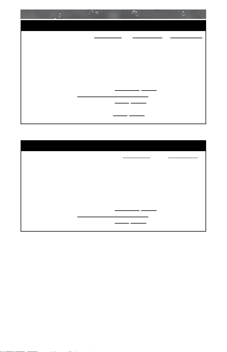
North American J-335, J-345, J-355, J-365, J-375 and J-385 Models
(60 Hz)
240V/40A* 240V/50A** 240V/60A***
Circuit Breaker (2-Pole): 40A 50A 60A
Number of Wires: 3 3 3
Frequency: 60 Hz 60 Hz 60 Hz
Current Draw: 26A 36A 45A
In 40A conguration, the heater will not operate while either jets
*
pump is running.
In 50A conguration, the heater will not operate while both jets
**
pumps are running. This is the factory setting.
In 60A conguration the heater will operate while both jets pumps
***
are running.
12
Page 19

J-300
North American J-315 and J-325 Convertible Models (60 Hz)
120V/15A† 240V/30A† 240V/40A
Circuit Breaker: 15A, 1-Pole 30A, 2-Pole 40A, 2-Pole
Number of Wires: 3 (15A GFCI
Cord US
Only*)
Frequency: 60 Hz 60 Hz 60 Hz
Current Draw: 12A 21A 30A
†
In 15A/30A conguration, the heater will not operate while the jets
pump is running. The factory setting is 120V/15A.
‡
In 40A conguration, remove jumper JP1-2 on the board, to allow the
heater to operate while the jets pump is running.
‡
Caution (For 4-wire 240 VAC Heater Operation): Move the red
wire on the main terminal strip (TB1) from position #1 to position
#3. Make certain wires are connected exactly as shown in Figure
D (page 17) before applying power. Failure to do so will result in
damage to the circuit board and/or related components and void the
manufacturer’s warranty.
4 (Hard Wire
Only)
4 (Hard Wire
Only)
‡
13
Page 20
J-300
Export J-335, J-345, J-355, J-365, J-375 and J-385 Models (50 Hz)
230V/20A* 230V/30A** 230V/40A***
RCD Breaker: 20A 30A 40A
Number of Wires: 3 3 3
Frequency: 50 Hz 50 Hz 50 Hz
Current Draw: 15A 23A 29A
Wattage: 3.5 kW 5.3 kW 6.7 kW
In 20A conguration, the heater will not operate while either jets
*
pump is running. This is the factory setting.
In 30A conguration, the heater will operate while one jets pump
**
is running.
In 40A conguration the heater will operate while both jets pumps
***
are running.
Export J-315 and J-325 Models (50 Hz)
230V/20A* 230V/30A**
RCD Breaker: 20A 30A
Number of Wires: 3 3
Frequency: 50 Hz 50 Hz
Current Draw: 15A 21A
Wattage: 3.5 kW 4.8 kW
In 20A conguration, the heater will not operate while the jets
*
pump is running. This is the factory setting.
In 30A conguration, the heater will operate while the jets pump is
**
running.
14
Page 21

J-300
7.0 Electrical Wiring Instructions
IMPORTANT NOTICE: The electrical wiring of this spa
must meet the requirements of the National Electrical
Code/USA (NEC) and any applicable state or local
codes. The electrical circuit must be installed by a
qualied electrician and approved by a local building/
electrical inspection authority.
1. Convertible 120/240V Power Models:
!
•
120V “Plug-in” Operation: This spa must operate on the supplied
• Convertible 120/240V Operation: The included 120V GFCI cord
2. Dedicated 240V models must be permanently connected (hard-
DANGER: TO DECREASE THE RISK OF SHOCK,
PRODUCT DAMAGE OR ELECTRICAL FIRE.
10 foot (3m) GFCI cord at its original length or must be hard-wired
for longer runs. NEVER USE AN EXTENSION CORD FOR ANY
REASON!
must be discarded for 240V operation. This spa must be hard
wired. Supplying power to either conguration above which is not in
accordance with these instructions will void both the independent
testing agency listing and the manufacturer’s warranty.
wired) to the power supply. No plug-in connections or extension
cords are to be used in conjunction with the operation of this spa.
Supplying power to the spa which is not in accordance with these
instructions will void both the independent testing agency listing and
the manufacturer’s warranty.
3. The power supplied to this spa must be a dedicated circuit with no
other appliances or lights sharing the power provided by the circuit.
4. To determine the current, voltage and wire size required, refer to
Section 6.0 “Power Requirements” (page 12).
• Wire size must be appropriate per NEC/USA and/or local codes.
• We recommend type THHN wire.
• All wiring must be copper to ensure proper connections. Do not use
aluminum wire.
5. When using wire larger than #6 (10 mm²), add a junction box near
the spa and reduce to short lengths of #6 (10 mm²) wire to connect
to the spa.
6. The electrical supply for this product must include a suitably rated
switch or circuit breaker to open all ungrounded supply conductors
to comply with Section 422-20 of the National Electrical Code/USA,
ANSI/NFPA 70. The disconnecting means must be readily accessible
to the spa’s occupant but installed at least 5 feet (1.5m) from spa
water.
15
Page 22
J-300
7. The electrical circuit supplied for the spa must include a suitable
ground fault circuit interrupter (GFCI) as required by NEC/USA Article
680-42.
8. To gain access to the spa’s power terminal block, press the release
button securing the synthetic cabinet panel under the control panel
(Figure A). Then remove the four control box door screws and door
(Figure B).
9. Select the power supply inlet you want to use (Figure A). Feed power
cable to control box, then install it through the large opening provided
in the bottom side of the box.
10. Connect wires, color to color, on terminal blocks TB1 and TB3
(Figure C, page 17). TIGHTEN SECURELY! All wires must be
hooked up securely or damage could result.
11. Install control box door and screws and reinstall the cabinet panels.
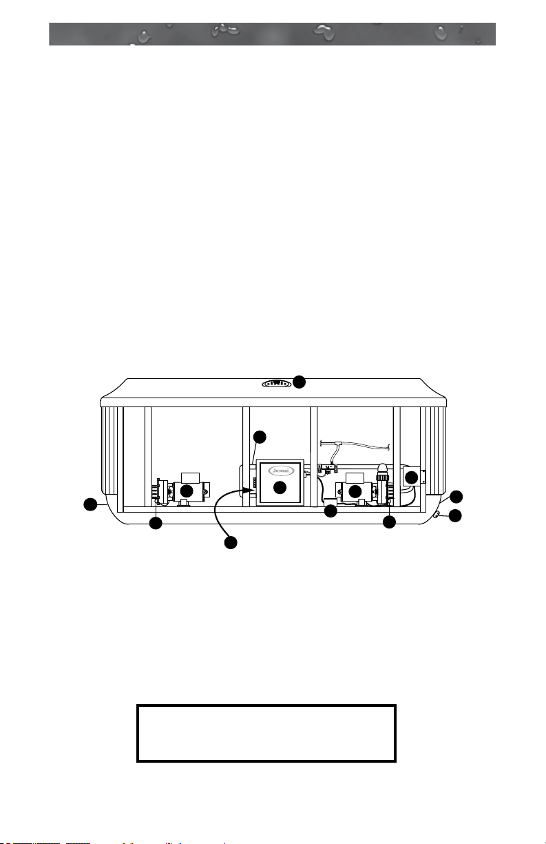
Figure A
Equipment Area
9
2
7
6
1. Control Box
2. Power Supply Entrance(s)
3. 1-Speed Jets Pump
4. Heater
5. Spa Drain Valve
6. Pump Drain Plugs(s)
Note: Equipment location (such as pumps,
CLEARRAY system, drain, heater etc.)
varies by model.
16
4
1
8
Circulation Pump
Behind Load Box
7. 1-Speed Jets Pump
8. Circulation Pump
9. Control Panel
10. CLEARRAY® (Ultraviolet) Water
Purication System
11. Electronic Ballast (for the CLEARRAY
System)
3
11
6
10
2
5
Page 23

Figure B Control Box
J-300
2
TB1
1
3
1. Terminal Block
2. Bonding Lug
3. Grounding Terminal
Figure-C
Power In
WHT
BLK
TB1
1
2
3
GRN
WHT
RED
BLK
BLK
to Circuit
Board
North American Convertible
Models: 120 VAC, 3-Wire Connection
60 Hz
Figure-D
Power In
North American Convertible
Models: 240 VAC, 4-Wire Connection
60 Hz
WHT
BLK
RED
2
1
3
GRN
TB1
WHT
BLK
BLK
RED
to Circuit
Board
RED
Move Red
Wire Here
Caution (For 4-wire 240 VAC Heater Operation): Move the red
wire on the main terminal strip (TB1) from position #1 to position #3.
Make certain wires are connected exactly as shown in Figure D before
applying power. Failure to do so will result in damage to the circuit
board and/or related components and void the manufactures warranty.
Figure-E
Power In
RED
BLK
Green
TB1
1
2
RED
RED
BLK
BLK
to Circuit
Board
TB3
North American 240V Models:
240 VAC, 3-Wire Connection 60 Hz
to Circuit
Figure-F
Board
BLUE BROWN
BLUE
1
BROWN
TB1TB2
2
Power In
TB3
Green
All Export Models: 230 VAC, 3-Wire
Connection 50 Hz
17
Page 24

J-300
8.0 Spa Fill Up Procedure
For best results, read each step in its entirety before proceeding with that
step.
1. Prepare The Spa For Filling
• Clear all debris from the spa. (Although the spa shell has been
polished at the factory, you may want to treat it with a specially
formulated spa cleaner.) Consult your authorized Jacuzzi dealer for
additional information prior to lling spa.
• Remove lter cover, then remove lter cartridge as outlined in
Section 12.1 (page 36).
2. Fill Spa
• Place the end of your garden hose into the empty lter bucket.
CAUTION: TO DECREASE BUILD UP ON COMPONENTS AND
MINIMIZE ACRYLIC DAMAGE.
Never ll with water from a water softener. If your water is extremely
“hard,” it is preferable to ll half-way with hard water and the rest of
the way with softened water. Water that is too soft can be corrosive
to metal components.
!
•
Fill hot tub with clean tap water from garden hose, to reduce risk of
WARNING: TO DECREASE RISK OF INFECTION OR
DISEASE.
contracting a waterborne
and/or respiratory ailments
touch the bottom of the lowest headrest. (DO NOT OVERFILL!)
illness (e.g. an infection, bacteria or virus)
. Fill until water covers all jets but does not
IMPORTANT: Always ll your spa through the lter bucket after
draining. Failure to do so may cause air to be trapped in either
pump, preventing the pump from circulating water. Remove the
hose and replace the lter cartridge. Note: DO NOT overtighten
lter cartridge, nger tight only!
3. Turn On Power
Turn on power to spa at the home’s circuit breaker to start boot up
sequence (Sec. 10.0, page 25). The heater and lter pump will
automatically activate after several seconds. If the control panel LED
ashes water temperature and “COL” or “ICE” this is normal, refer to
page 49 for additional information.
Note: “COL” will only appear when the spa is in Economy mode.
4. Activate Jets Pumps
Turn on jets pump(s) to ensure proper mixing when adding
start-up chemicals in step 5.
18
Page 25

J-300
5. Add Start-Up Chemicals
Add the spa water chemicals as recommended by your authorized
Jacuzzi dealer. See Section 13.0 “Water Quality Maintenance” (page
43) for general guidance.
WARNING: RISK OF POISONING OR DEATH.
Never leave chemicals opened and accessible to anyone. Use
!
chemicals according to the vendors instructions. Always store
chemicals in a safe and/or locked location. Keep away from
and out of reach of children.
6. Establish A Stable Sanitizer Reading
Establish a stable sanitizer reading of no less than 1.0 ppm free chlorine
or 2.0 ppm bromine. To ensure healthy water conditions, always maintain
a constant sanitizer reading within the levels recommended on the inside
cover of this manual. If sanitizer levels cannot be stabilized, perform the
decontamination procedure steps 9-15 on the following page.
Note: The “decontamination procedure” steps 9-16 should also be used
after the spa has been “Winterized” (Section 12.8, page 42) or has
been sitting without power for an extended period.
7. Set Spa To Heat
To warm spa water to a comfortable temperature, follow these
steps:
• The LED display on the control panel displays the actual
temperature of the spa water. Press either the COOLER ( ) or
WARMER ( ) button once to display the “set” temperature for 5
seconds. If you want the water to heat to a different temperature,
simply press COOLER ( ) or WARMER ( ) within 5 seconds.
The set temperature increases or decreases by one degree each
time one of these buttons is pressed.
• The heater will turn off when the temperature corresponding to the
thermostat setting is achieved.
Important Heater Details:
• The maximum water temperature setting for your spa is 104°F
(40°C) and the minimum setting is 65°F (18°C).
• For North American spas connected to a 40 amp service, jets pump
#1 and jets pump #2 must be turned off to operate the heater.
• For Export spas connected to a 20 amp service, jets pump #1 and
jets pump #2 must be turned off to operate the heater.
• Setting the thermostat at maximum will not accelerate the heating
process. This will only result in a higher ultimate temperature.
• The heater operates until the water reaches the programmed “set
temperature,” then turns off. The heater will reactivate after the
water cools to approximately 1.5° below the set temperature.
19
Page 26

J-300
8. Place Cover On Spa
• Keeping the insulating cover in place anytime the spa is not in
use will reduce the time required for heating, thereby minimizing
operating costs.
• The time required for initial heat-up will vary depending on the
starting water temperature.
DANGER: RISK OF PERSONAL INJURY.
Check water temperature carefully before entering hot tub!
!
Excessive water temperature can cause burns, welts and body
temperature to rise, hyperthermia (over-heating).
Decontamination Procedure (Steps 9-16)
Steps 9-16 below are only required when sanitizer levels are unstable
after performing steps 1-6 above. Disregard steps 9-15 below if sanitizer
levels remain stable after performing steps 1-6 above (refer to the inside
cover of the manual).
9. Add 2.5 ounces (71 g) of sodium dichlor for every 100 gallons (378
Liters) of water. Refer to the table below for approximate water ll
volume by model.
CAUTION: RISK OF PERSONAL INJURY OR SPA DAMAGE!
Never add chlorine tablets (trichlor) or acid to your hot tub for
!
any reason! These chemicals may damage components within
your hot tub, burn or irritate your skin, create a rash, and void
the manufacturer warranty for your spa.
Water Fill Volume by Model
Spa Model Average Fill Volume* Sodium Dichlor
J-385 TBA Gal (TBA L) TBA oz
J-375 415 Gal (1,571 L) 10.5 oz
J-365 400 Gal (1,514 L) 10.0 oz
J-355 390 Gal (1,476 L) 10.0 oz
J-345 340 Gal (1,287 L) 8.5 oz
J-335 330 Gal (1,249 L) 8.0 oz
J-325 325 Gal (1,230 L) 8.0 oz
J-315 210 Gal (795 L) 5.0 oz
*Use average ll volume for chemical maintenance
20
Page 27

J-300
10. Leave spa cover open during this step to allow
excessive chemical vapors to exit spa, protecting
pillows and plastic knobs from chemical attack. If
spa is indoors, open doors and windows for proper
ventilation. Turn on all jet pumps for one hour,
then place the massage selector knob in the
center “combo” position and open all air controls.
Note: You will need to press the jets pump button(s) every 20 minutes
since these functions have an automatic 20 minute time-out function that
turns them off.
WARNING: RISK OF PERSONAL INJURY!
• To decrease the risk of injury, drowning or entrapment,
!
11. Turn off power to the spa at the circuit breaker, then drain spa as
outlined in Section 12.2 “Draining and Relling” (page 39).
12. Fill spa until water covers all jets but does not touch the bottom of
the lowest headrest. DO NOT OVERFILL.
never leave your hot tub unattended for any reason while
the cover is open and accessible, especially to small chil-
dren and animals!
• Precautions should be taken to minimize your exposure
to chemical vapors (that could cause lung, brain, or skin
damage).
CAUTION: TO DECREASE BUILD UP ON COMPONENTS AND
MINIMIZE ACRYLIC DAMAGE.
Never ll with water from a water softener. If your water is extremely
“hard,” it is preferable to ll half-way with hard water and the rest of
the way with softened water. Water that is too soft can be corrosive
to metal components.
13. Consult your authorized Jacuzzi dealer for chemical
recommendations, then add chemicals to hot tub water to achieve
a constant sanitizer reading within the levels recommended on the
inside cover of this manual.
14. Turn on all jets pump(s) when adding chemicals to ensure proper
mixing and leave your hot tub cover open until the sanitizer level
becomes stable to protect pillows and plastic knobs from chemical
attack. Refer to the inside cover of the manual.
21
Page 28

J-300
WARNING: RISK OF PERSONAL INJURY.
• To decrease the risk of injury, entrapment or drowning,
!
15. Establish a sanitizer reading no less than 1.0 ppm free chlorine
or 2.0 ppm bromine, then allow the hot tub to set undisturbed for
8 hours. Retest water after 8 hours to determine if sanitizer levels
are stable. If sanitizer levels are stable, your spa is ready for use.
To ensure healthy water conditions, always maintain a constant
sanitizer reading within the levels recommended on the inside cover
of this manual. If sanitizer levels are not stable at this time, it will be
necessary to repeat this procedure in its entirety (steps 1-15) until
stable sanitizer readings are achieved.
IMPORTANT: If the CLEARRAY ® water purication system is removed
from the hot tub or is not operating effectively follow the “without
CLEARRAY®” water chemistry parameters as dened by the Association
of Pool and Spa Professionals.
never leave your hot tub unattended for any reason, es-
pecially if while the cover is open and accessible to small
children and animals!
• To decrease the risk of contracting a waterborne
(e.g. an infection, bacteria or virus) and/or respiratory ailments, maintain water chemistry within 6 step parameters.
If you or other bathers experience such a condition, discon-
tinue use and seek immediate medical attention.
illness
16. After adequate sanitizer levels are achieved, close all spa air controls
to maximize heat retention when spa is not in use.
22
Page 29

J-300
9.0 Control Functions
9.1 Control Panel
A. CLEARRAY ( )Button:
Manually activates the
A
C
D
CLEARRAY system for a
one-hour period.
B. CLEARRAY Indicator Light: Lit when the CLEARRAY system is on.
Flashing when the UV bulb needs to be replaced.
C. Light On/Off ( ) Button Options: Turns waterfall light, footwell
light, lighted cup holders and backlit pillows on in unison. Press
once for high intensity; press a second time for medium intensity;
press a third time for low intensity; press a fourth time to turn off. The
displayed color is changed using the light mode button (D) below.
D. Light Mode ( ) Button: Selects one of 4 light color modes for
waterfall, footwell, cup holders, and pillow lights. See page 26 for
additional information.
E. Cooler ( ) Button: Decreases water temperature set point. Also
used to navigate through the programming menus.
F. Warmer ( ) Button: Increases water temperature set point. Also
used to navigate through the programming menus.
G. Jets 1 ( ) Button: Turns jets pump #1 on and off. Press once to
turn pump #1 on; press a second time to turn pump #1 off.
K
E
F
2-Pump Control Panel Shown
JB
I
H
G
1
2
H. Jets 2 ( ) Button (J-335 to J-385): Turns jets pump #2 on and
off. Press once to turn pump #2 on; press a second time to turn
pump #2 off.
I. Menu ( ) Button: Allows access to the programming menus.
J. Heat Indicator: Lit when heater is on.
K. LED Display: Can display current water temperature (default
display), water temperature set point, selected menu functions, and
error messages.
Operation Details
• Temperature Adjustment: 65 to 104°F (18 to 40°C). Factory default
setting is 100°F (38°C).
• CLEARRAY Operation: System runs for 1 hour (when manually
activated), then automatically shuts off.
• Light Operation: All LED lights run for 2 hours, then automatically
shut off.
• Jets 1/Jets 2 Button Operation: Jets run for 20 minutes when
activated, then turn off automatically to conserve energy. Simply
press either jets button to continue operation for an additional 20
minutes.
23
Page 30

J-300
9.2 General Spa Features And Controls
2
4
21
15
6
16
18
8
10
12
2121
17
2
3
5
4
14
2
21
16
8
2
20
J-385 model illustrated - Location of Features Varies by
Model. Specications/features subject to change without
notice.
16
4
17
15
16
5
16
14
6
5
13
15
4
15
19
7
13
18
11
8
19
15
1919
9
1
1. Control Panel
2. Toggle Air Controls
3. Filter/Skimmer Grill
4. Backlit Pillows
5. Lighted Cup Holders*
*Light features not offered
on J-315/J-325 Models.
6. Massage Selector Valves
7. Waterfall Feature
8. Footwell Suction Fittings
9. Spa Light
10. Heater Return Fitting
SpecicationsSubjecttoChangeWithoutNotice.
24
11. Waterfall overflow
12. PowerPro MX Jets
13. PowerPro FX2 Spinner Jets
14. PowerPro FX2 Jets
15. PowerPro FX Jets
16. PowerPro FX SpinnerJets
17. PowerPro NX2 Jets
18. PowerPro BX Jets
19. PowerPro Mini FX Jets
20. Optional BLUEWAVE™ Spa
Stereo System
21. Optional Stereo System
Speakers
Page 31

J-300
10.0 Operating Instructions
The spa control system has automatic functions that operate upon
start-up and normal operation to protect the system. Upon power up, the
readout displays the following information:
1. Control panel displays current software release, then;
2. Control panel displays “888” and all indicator LEDs are lit, permit-
ting visual inspection of all display segments and indicator lights for
proper operation.
3. After the initial start-up sequence ends, the actual water temperature
is displayed. If water temperature, at this time, is less than the factory default temperature setting of 100°F (38°C) the heater will turn
on and run until the water temperature rises to the factory setting,
then turn off.
Note: It is common for the heater to turn on after the spa is rst lled
because tap water is often very cold.
10.1 Setting Water Temperature
Press either the Warmer ( ) or Cooler ( ) button to
adjust the current temperature setting. The current set temperature reading will blink once to indicate
that the system is ready to accept changes.
Press the Warmer or Cooler button to
adjust the temperature to a desired setting.
Once the desired temperature is reached,
do not press any buttons on the control
panel for about 5 seconds. The new tem-
perature setting will blink twice to indicate
that the change has been made.
To access the overtemp feature that allows the spa to reach 106°F
(41°C) follow the steps below (Figure 1).
1
2
Figure 1
WARNING: RISK OF HYPERTHERMIA (OVER-HEATING)
CAUSING SEVERE INJURY, BURNS, WELTS OR DEATH!
!
Water temperature in excess of 104°F (40°C) may be injurious
to your health.
A. Press and hold the WARMER ( ) button then;
B. Press and hold the JETS 1 ( ) button at the same time for 2
seconds. You will see the temperature change to 105°F (40°C) on
the LED display. Press the WARMER ( ) to raise the temperature
to 106°F (41°C) To lower the temperature, press the COOLER ( )
button.
C. When the overtemp has been activated, the decimal point after the
last digit will ash on and off every second as an indicator for being
in the overtemp mode.
Note: Once the temperature goes below 104°F (40°C) and you would
like to raise the temperature to 106°F (41°C) again, you will have to
repeat the steps above.
25
Page 32

J-300
10.2 Activate Jet Pumps
The JETS 1 button activates jets pump 1. The rst press
turns jets pump 1 on; the second press turns jets pump 1
off. The JETS 2 button activates jets pump 2 (if equipped).
turns jets pump 2 on; the second press turns jets pump 2 off. When
manually activated, either pump will automatically turn off after 20
minutes.
10.3 Light On/Off Button
Pressing this button activates the waterfall light, footwell light,
lighted cup holders, and backlit pillows lights in unison as
follows: high - medium - low - off.
Note: Lights automatically turn off after 2 hours.
10.4 Light Mode Button
This button offers 4 light modes for your enjoyment. Press this
button to select your favorite lighting effect as follows:
Press
Once
Press
Again
Press
Again
Press
Again
Selects or “freezes” your low speed blending color of choice.
BLUE (X4) VIOLET (X5) RED (X6)
Selects one of 7 solid (high-intensity) colors of choice.
High-Speed Color Blend Mode
Low-Speed Color Blend Mode
Freeze Color Blend Mode:
AMBER (X7) GREEN (X8) AQUA (X9) NEAR
Solid Color Mode:
WHITE (X10)
10.5 Jets
The water ow through individual jets in your spa can be
adjusted or turned off by rotating the outside jet ring. Some jets
offer an adjustable center nozzle that allows you to change the
water discharge angle. Simply tilt the center nozzle in these jets
to the desired angle to customize your personal massage.
Other jets offer a spiral action that produces a surging stream of
air and water that provides a vigorous massage.
Note: Always keep at least 6 adjustable jets open at all times to ensure
proper ltration characteristics within the spa.
26
Page 33

J-300
10.6 Selecting Desired Massage Action
All models incorporate a massage selector valve that
allows you to customize the massage and performance
by diverting water between various jet systems within the
spa. Simply turn valve to positions A, B or C to divert
water pressure to various jet groups.
Note: The valve is intended to operate in positions A (Combo), B, or C
for optimum performance. It is considered normal for sound levels within
the valve to increase between these positions due to the large amounts
of water owing through it. For optimum ltration benets, always leave
this valve in position A when the spa is covered and select positions B or
C for maximum jet performance during spa use.
10.7 Waterfall Feature
The waterfall feature allows you to independently control it for a
customized soothing effect. The waterfall is on when the circulation pump
is on. The JETS 1 or CLEARRAY buttons will also activate the waterfall
feature.
Waterfall Operation Details:
A. Push thumb wheel on top of waterfall to the left
(while in spa) to start or increase ow.
B. Push thumb wheel on top of waterfall to the right
(while in spa) to slow or turn ow off.
Note: When the waterfall is in the OFF position, some water could still
ow through.
CB
A
10.8 Air Controls
Certain jet systems have their own “toggle” on/off air control.
Each control introduces air into the water lines that supply
specic jet groups. Simply press any air control button
Jacuzzi logo side down to open or press the opposite side
of button to close.
Note: To minimize heat loss, close all air controls (Jacuzzi logo up) when
spa is not in use.
10.9 Optional BLUEWAVE™ Spa Stereo
System
Spas equipped with the optional audio system
offer enhanced enjoyment. These models include
a high-quality FM/USB/AUX/Bluetooth stereo
receiver with four high-quality marine speakers for
unsurpassed sound quality and long-life.
Note: Digital rights management (DRM) les
AUDIO
2
1
3
REPEAT RANDOMDIR - DIR +
cannot be played. Personal les (MP3, WMA, iTunes or AAC)
can be played as long as they are not DRM encrypted les.
27
MODE
Page 34

J-300
11.0 Menu Features and Programming Instructions
Your spa is equipped with ve menus that allow you to program
additional features. By continually pressing the Menu button you will
cycle through the menus as follows (Figure 1):
Current temperature (Main Menu)
Primary Filtration Menu
Secondary Filtration Menu
CLEARRAY/UV Menu
Economy Menu
Lock Menu
Figure 1
A. Primary Filtration Menu
Allows access to the programming menu for the primary ltration that
uses the circulation pump, page 29. Although the spa has a default
setting this feature is programmable. While in this menu, you can also
program the Change Filter Timer.
B. Secondary Filtration Menu
Allows access to the programming menu for the secondary ltration
that uses Jets Pump 1, page 32. These cycles are used to provide
additional skimming. Although the spa has a default setting this feature is
programmable.
C. CLEARRAY Menu
Allows access to the CLEARRAY® bulb replacement countdown timer,
page 33. Your spa is equipped with the CLEARRAY system that uses
a UV bulb to purify the water. This bulb must be replaced every year.
By programming the countdown timer, a reminder is displayed on the
topside when it is time to replace the bulb. The LED screen will ash
between “blb” and the set temperature. Additionally, the CLEARR AY
indicator light will blink, page 23. The timer needs to be reset in order
to clear the message.
D. Economy Menu
Allows access to the economy programming menu, page 33. The
economy feature has either an “on” or “off” setting where the heater
is allowed to activate for a maximum of 30 minutes at the end of each
secondary ltration cycle.
E. Lock Menu
Activates the locking modes to certain components, features or
operations, page 35.
28
Page 35

J-300
11.1 Primary Filtration Menu
During the primary ltration cycle, the circulation pump and CLEARRAY
are activated. The spa is programmed with a factory default setting but
can be programmed to any of the cycle settings listed below. These
cycles allow the circulation pump to run for preset amounts of time per
day, in addition to the normal operation. Should the circulation pump
activate outside of a preset cycle (except for PF0 and PF6), e.g. when
heating, that run time will reduce the length of the next cycle.
Note: To set a time for the primary ltration cycle to begin, simply turn
power on to the spa two minutes prior to the desired time. You can also
press the Warmer, Cooler and Jets Pump 1 buttons simultaneously for 2
seconds to restart the spa once power has been provided.
No ltration
4 hours of ltration per day
8 hours of ltration per day (default setting for J-335 to
J-385)
12 hours of ltration per day
16 hours of ltration per day
20 hours of ltration per day
24 hours of ltration per day (default setting for J-315
and J-325)
2 hours of ltration – 4 times per day
3 hours of ltration – 4 times per day
In extreme bitter cold weather we recommend you program
the primary ltration cycle to run 24 hours. Refer to the "Winterizing" section on page 42.
A. For Models J335 to J385
Two minutes after power is applied to the spa, an automatic primary
ltration cycles begins. The circulation pump is activated and set to run
for 8 hours a day (factory default). The circulation pump draws water
through the skimmer bag and one of two lter cartridges to effectively
remove small debris in your spa. During the primary ltration cycle, the
circulation pump and CLEARRAY are activated. The factory default
setting is PF2. This setting is programmable.
Note: The circulation pump also supplies heated water to the spa when
the heater turns on. Any time the circulation pump runs outside of
a programmed cycle (except for PF0 and PF6), that run time will
reduce the length of the next cycle.
29
Page 36

J-300
To remove larger debris missed by the primary ltration system, the
control system can activate a secondary ltration system. These cycles
utilize Jets Pump 1 and the second lter cartridge to quickly “skim” the
water of large debris and minimize their “bath-tub ring” effect.
B. For Models J315 and J325
Your new spa includes a 24-hour primary ltration system, which
lters the water continuously (factory default). The circulation pump
draws water through the skimmer bag and one of the two lter cartridges
to effectively remove small debris in your spa. The factory default setting
is PF6. This setting should not be altered. Running the circulation pump
less than the factory recommended time will result in issues with water
quality maintenance.
Note: The 24-hour primary ltration system also supplies heated water to
the spa when the heater turns on.
To remove larger debris missed by the 24-hour primary ltration system,
you can program a secondary ltration system. The secondary ltration
cycles use Jets Pump 1 and the second lter cartridge to quickly “skim”
the water of large debris and minimize their “bath-tub ring” effect.
11.2 Programming the Primary Filtration Cycle
To make changes to the primary ltration cycle, follow the steps below.
PRESS PRESS PRESS
PRESS
◄
◄ ◄◄
PRESS
◄
◄
◄
PRESS
A. Press the Menu (
◄
PRESS
◄
PRESS
) button once to access the
◄ ◄
PRESS PRESS
Figure 2
program settings. The LED screen will display “PF.”
B. Press the Warmer ( ) or Cooler ( ) button to prepare the
system for changes. The LED will display the last cycle programmed
and will blink once to indicate the system is ready to accept changes.
C. Press the Warmer ( ) or Cooler ( ) button to scroll through the
cycles, PF0 to PF8, Figure 2.
D. Once a cycle is selected, press the Jets Pump 1 ( ) button to
conrm the selection. You must press the Jets Pump 1 ( ) button
to conrm your selection or the current settings will remain active.
E. The display will show the new cycle selected and it will blink twice to
indicate that the change has been accepted.
Note: If no button is pressed within 5 seconds of each selection the
screen will revert back to the Main Menu and the current settings will
remain active.
30
Page 37

J-300
11.3 Programming the Change Filter Timer
Included within the Primary Filtration Menu, is the Change Filter feature.
To make changes to the change lter timer or to reset it, follow the steps
below.
PRESS
PRESS
OR
PRESS
Figure 3
A. Press the Menu (
) button once to enter the Primary Filtration
Menu. The LED screen will display “PF.”
B. Press the Warmer ( ) button to scroll through the Primary
Filtration cycles. After the last cycle, “PF8,” the LED screen will
display the number of days remaining or zero, Figure 3.
Note: If you press the Warmer ( ) button after the number of days
remaining you will revert back to the “PF” menu. You will need to repeat
step B to re-enter the menu.
C. Press the Jets Pump 1 ( ) button to access the Change Filter
Timer. The display on the LED screen will blink once to indicate that
the system is ready to accept changes.
D. Pressing the Warmer ( ) or Cooler ( ) button will add or
subtract days in increments of 10 days. The range is from 0 to 180
days.
E. Once you select the number of days, press the Jets Pump 1 ( )
button to conrm the selection. The display of the LED screen will
blink twice to indicate that the changes have been accepted. You
must press the Jets Pump 1 ( ) button to conrm your selection
or the current settings will remain active.
F. When the countdown timer reaches “0,” the LED
display will ash between “CF” (Figure 4) and the water
temperature. At this time the lters must be replaced or
Figure 4
cleaned and the timer reset.
Note: If no button is pressed within 5 seconds of each selection the
screen will revert back to the Main Menu and the current settings will
remain active.
31
Page 38

J-300
“SF” menu
11.4 Secondary Filtration Menu
The jets pump 1 activates during the secondary ltration to provide
additional skimming. The spa is programmed with a default setting of
SF0 but can be programmed to any of the cycle settings listed below,
Figure 5. These cycles schedule the jets pump 1 to run for a preset
amount of time per day, in addition to normal operation.
Note: During the secondary ltration the jets pump 1, circulation pump
and CLEARRAY are activated.
No ltration
10 minutes of ltration every 12 hrs
10 minutes of ltration every 8 hrs
10 minutes of ltration every 6 hrs
Figure 5
11.5 Programming the Secondary Filtration Cycle
To make changes to the Secondary Filter Cycle, follow the steps below.
PRESS
PRESS
◄
PRESS
◄
PRESS
◄
◄
OR
Will return to
Figure 6
A. Press the Menu (
) button twice to display the Secondary
Filtration Cycle Menu. The LED screen will display “SF.”
B. Press the Warmer ( ) button to prepare the system for changes.
The LED will display the last cycle programmed and will blink once to
indicate the system is ready to accept changes.
C. Press the Warmer ( ) or Cooler ( ) button to scroll through the
cycles, SF0 to SF3 (Figure 6).
D. Once a cycle is selected, press the Jets Pump 1 ( ) button to
conrm the selection. You must press the Jets Pump 1 ( ) button
to conrm your selection or the current settings will remain active.
E. The display will show the new cycle selected and it will blink twice to
indicate that the change has been accepted.
Note: If no button is pressed within 5 seconds of each selection the
screen will revert back to the Main Menu and the current settings will
remain active.
32
Page 39

J-300
the “U” menu
11.6 Programming the CLEARRAY Bulb Replacement Timer
To make changes to the CLEARRAY bulb replacement timer or to reset
it, follow the steps below (Figure 7).
Adds days in
PRESS
Activates
submenu for
changes
PRESS
OR
Will return to
Blinks once
PRESS
OR
10-day increments
Substracts days
in 10-day increments
PRESS
Blinks twice
Figure 7
A. Press the Menu (
) button three times to display the CLEARRAY
Bulb Replacement Timer Menu. The LED screen will display “U.”
B. Press the Warmer ( ) button to enter the menu. The LED screen
will display the number of days remaining or zero.
Note: If you press the Warmer ( ) button after the number of days
remaining you will revert back to the “U” menu. You will need to repeat
step B to re-enter the menu.
C. Press the Jets Pump 1 ( ) button to access the CLEARRAY bulb
replacement timer. The display on the LED screen will blink once to
indicate that the system is ready to accept changes.
D. Pressing the Warmer ( ) or Cooler ( ) button will add or
subtract days in increments of 10 days except when 360 is reached.
Then a 5-day increment occurs. The range for programming is from 0
to 365 days.
E. Once you select the number of days, press the Jets Pump 1 (
)
button to conrm the selection. The display of the LED screen will
blink twice to indicate that the changes have been accepted. You
must press the Jets Pump 1 ( ) button to conrm your selection
or the current settings will remain active.
Note: If no button is pressed within 5 seconds of each selection the
screen will revert back to the Main Menu and the current settings will
remain active.
11.7 Economy Menu
In Economy mode, the heater only activates after a Secondary Filtration
cycle has nished. The heater will run for a maximum of 30 minutes.
The heater can turn off prior to the 30 minutes if the programmed
water temperature is reached. The Secondary Filtration program
determines the number of cycles (from 1 to 4) that the heater will be
allowed to activate. For example, if you have programmed the SF3
setting (10 minutes of ltration every 6 hours), then the heater will run,
for a maximum of 30 minutes, after the end of each of the 10-minute
secondary ltration cycle, for up to four times per day. Reference the
chart that follows.
33
Page 40

J-300
CYCLE RUN TIME HEATER RUN TIME
No ltration Maximum of a half hour per day
10 minutes of ltration
every 12 hrs
10 minutes of ltration
every 8 hrs
10 minutes of ltration
every 6 hrs
11.8 Programming the Economy Mode
To activate the Economy Mode, follow the steps below.
◄◄
▲
PRESS PRESS PRESS
◄
◄
◄
◄
Maximum of a half hour every 12 hrs
(after secondary cycle ends)
Maximum of a half hour every 8 hrs
(after secondary cycle ends)
Maximum of a half hour every 6 hrs
(after secondary cycle ends)
◄
▼
►
PRESS
OR
Figure 8
A. Press the Menu (
) button four times to display the Economy
Figure 9
Menu (Figure 8). The LED screen will display “ECO.”
B. Press the Warmer ( ) button to enter the menu. The LED screen
will display the current status of the Economy Mode setting, either
ON or OFF.
C. Press the Warmer (
) button to scroll through the settings.
D. Once the new setting appears of the display, press the Jets Pump
1 ( ) button to conrm your selection (Figure 9). The display of
the LED screen will blink twice to indicate that the change has been
accepted. You must press the Jets Pump 1 ( ) button to conrm
your selection or the current settings will remain active.
Note: If no button is pressed within 5 seconds of each selection the
screen will revert back to the Main Menu and the current settings will
remain active.
11.9 Lock Menu
The Lock menu gives you the option to lock specic features of the spa.
There are three locking modes, L1, L2 and L3.
Note: When a lock mode is active, the LED display will ash between the
lock mode and temperature.
L1 lock mode: The jets pumps and heater are deactivated. This mode
can be used when replacing or cleaning the spa lters.
Note: The spa should not be left in this lock mode for an extended period
of time. Especially in colder climate or when freezing conditions exist.
L2 lock mode: The jets pumps, adjust temperature and CLEARRAY
buttons are deactivated. This mode can be used to
prevent unauthorized use of the spa.
34
Page 41

L3 lock mode: The temperature and CLEARRAY buttons are
PRESS PRESS PRESS
►
◄
◄
▲
◄
◄
◄
◄
◄
PRESS
PRESS
◄◄
◄
◄
◄
deactivated. This mode can be used to prevent
unauthorized temperature adjustments.
J-300
11.10 Programming the Lock Modes
Figure 10
OR
PRESS
OR
OR
Figure 11
To activate and deactivate the lock modes, follow the steps below:
A. Press the Menu (
) button ve times to display the Lock Menu
(Figure 10). The LED screen will display “LOC.”
B. Press the Warmer ( ) button to enter the menu. The LED screen
will display the current status of the Lock Mode setting, either L1, L2,
L3 or OFF.
C. Press the Warmer ( ) button to scroll through the modes.
D. Once the new setting appears of the display, press the Jets Pump
1 ( ) button to conrm your selection (Figure 11). The display of
the LED screen will blink twice to indicate that the change has been
accepted. You must press the Jets Pump 1 ( ) button to conrm
your selection or the current settings will remain active.
Note: If no button is pressed within 5 seconds of each selection the
screen will revert back to the Main Menu and the current settings will
remain active.
11.11 Top Menu Lock
To prevent unauthorized use of the menu features, you can lock the
Menu access button. When the lock feature is activated, access to the
Primary Filtration, Secondary Filtration, CLEARRAY, Economy and Lock
programming menus is deactivated. The temperature setting feature, jets
pumps operation and lighting features are still accessible.
11.12 Programming the Top Menu Lock Feature
To activate the Top Menu locking feature, follow the steps below:
A. Press and hold the Menu ( ) button for 10 seconds.
B. The LED screen will display “LOC.” The LOC display will also blink
twice to indicate that the change has been accepted.
C. When done the LED display will return to the temperature display.
D. When the LOC feature is active, any time you press the Menu ( )
button, the LED will display “LOC.”
To deactivate the Top Menu locking feature, follow the steps below:
A. Press and hold the Menu ( ) button for 10 seconds.
B. The LED screen will display “LOC.” The LOC display will also blink
twice to indicate that the change has been accepted.
C. You will now have access to the Menus.
35
Page 42

J-300
12.0 Spa Maintenance
Proper and regular maintenance of your spa will help it retain its beauty
and performance. Your authorized Jacuzzi dealer can supply you with
all the information, supplies, and accessory products you will need to
accomplish this.
DANGER: RISK OF SEVERE INJURY OR DROWNING BY
!
ENTRAPMENT!
• Keep hair, loose articles of clothing or hanging jewelry away
from suction ttings, rotating jets or other moving components to
avoid entrapment that could lead to drowning or severe injury.
• Never use the spa unless all suction guards, lter, lter lid, or
skimmer assembly are installed to prevent body and/or hair
entrapment.
• Never operate or use the spa if the lter, lter lid, or skimmer
assembly are broken or any part of the skimmer assembly is
missing. Please contact your dealer or nearest service center
for service.
• The suction ttings and suction covers in this spa are sized
to match the specic water ow created by the pump(s). If it
is necessary to replace the suction ttings, suction covers or
pump(s), be sure that the ow rates are compatible and are in
compliance with the VGB Safety Act, page 2.
• Never replace a suction tting or suction cover with one rated
less than the ow rate marked on the original suction tting.
Using improper suction ttings or suction covers can create
a body or hair suction entrapment hazard that may lead to
drowning or severe injury.
• Owners must alert all spa users to the potential risk of Hair,
Limb, Body, Evisceration (disembowelment), and Mechanical
Entrapment, page 6.
12.1 Cleaning The Filters
Your Jacuzzi spa is equipped with a skimmer bag and two high
performance pleated lter cartridges located under the lter cover. The
circulation pump drawing water through the skimmer bag and lter
cartridge lters ne debris. Large debris is ltered by jets pump 1 drawing
water through the skimmer bag and second lter cartridge during an
automated Secondary Filtration Cycle or when jets pump 1 is manually
activated during spa use. Combined, both lters provide unsurpassed
water quality by trapping surface oils and suspended particles.
36
Page 43

J-300
An optional chemical feeder is available through your
authorized Jacuzzi dealer that installs under the lter cap
(#2472-673). Always remove the chemical feeder cap and
feeder (when used) during the lter cleaning process by
turning the cap handle counterclockwise. Reinstall the cap
and feeder back onto the lter cartridge after the lter
cleaning process is complete. It is recommended that latex
gloves be used to avoid touching the chemical feeder
during the lter cleaning process.
Note: When used, the chemical feeder MUST remain on the circulation
pump lter cartridge! This lter cartridge is the one with the grid across
the wall tting as shown (right).
TO DECREASE RISK OF DEATH, DROWNING OR ENTRAPMENT,
ALWAYS TURN POWER TO SPA OFF BEFORE CLEANING THE
FILTER CARTRIDGES!
Note: Refer to steps on following page for complete lter cleaning/
replacement instructions.
A
DANGER: TURN POWER TO SPA OFF! TO DECREASE
RISK OF DEATH, DROWNING, OR ENTRAPMENT, NEVER
OPERATE SPA WHEN FILTER IS NOT PROPERLY INSTALLED
OR IF SKIMMER ASSEMBLY IS DAMAGED OR ALTERED!
B
Lift cover approx. 3/8" to
unclip, then tilt forward to
access lter cartridges.
C
(Filter Cover Back View)
Remove skimmer bag
from clips, then clean out
debris.
D
Rotate each lter
cartridge handle
counterclockwise to
unthread from mating
wall tting.
37
Page 44

J-300
E
Lift unthreaded lter
cartridge from skimmer
well.
H
F
If used, remove the
chemical feeder as
instructed prior to rinsing
the lter cartridges.
Rinse debris from lter
pleats on each cartridge
using a garden hose and
high pressure nozzle.
Start at the top and
work downward towards
handle. Repeat until all
pleats are clean.
I
G
Trapped
Air
Bubbles
Cartridge 1
Cartridge 2
Submerge both lter
cartridges in spa. Tilt
threaded end upward
to remove trapped air
bubbles, then keep
cartridges submerged to
prevent air entrapment
during installation (step
H).
J
Place each cartridge
back into skimmer
well, then rotated
each cartridge handle
clockwise to thread back
into wall tting. DO NOT
OVERTIGHTEN!
38
(Filter Cover Back View)
Install clean skimmer
bag back onto the lter
cover clips as shown.
Tilt lter cover back
against clips, then lift
approx. 3/8" to latch
against spa shell. Turn
power to spa back on.
Page 45

J-300
Periodically, the lter cartridge will need a more thorough cleaning to
remove imbedded oils and minerals. For this, we suggest cleaning
followed by soaking the lter overnight in a plastic container lled with
a solution of water and specially formulated lter cleanser available
from your authorized Jacuzzi dealer. The average life expectancy of
each lter is approximately two years with proper care and water quality
maintenance. Replacement cartridges may be purchased from your
authorized Jacuzzi dealer.
12.2 Draining and Relling
About every 3 months, you will want to replace the spa’s water. The
frequency depends on a number of variables including the amount of
use, attention paid to water quality maintenance, etc. You will know it is
time for a change when you cannot control sudsing and/or you can no
longer get the normal feel or sparkle to the water even though the key
water balance measurements are all within the proper parameters.
CAUTION! READ THIS BEFORE DRAINING: To prevent damage
to the spa’s components, turn off power to the spa at the circuit
breaker before draining it. Do not turn the power back on until
yourspahasbeenrelled.
CAUTION: There are certain precautions to keep in mind when
draining your spa. If it is extremely cold, and the spa is outdoors,
freezing could occur in the lines or the equipment, see “WINTERIZING” (page 42). On the other hand, if it is hot outdoors, do not
leave the spa’s surface exposed to direct sunlight.
To drain your spa, perform the following steps:
1. Turn off power to spa.
1. Turn off power to spa at breaker.
2. Locate the drain valve on the front/lower plastic
pan. Hold the larger (rear) body to prevent
2.
it from turning, then loosen and remove the
front cap to expose the underlying male hose
3.
threads.
3. Attach a garden hose to the exposed threads.
4. Gently rotate the larger (rear) valve body 1/3
4.
turn counterclockwise to unlock the drain valve.
5. Pull the larger (rear) body outward to open drain.
6. After the spa drains, perform steps 2-5 in
reverse order to close the drain prior to relling
the spa.
5.
Open Drain
After relling, turn on power to the spa and follow
the steps listed under “Spa Fill Up Procedure” (page 18). Always ll
your spa through both lter wall ttings.
Unlock
Drain
39
Page 46

J-300
12.3 Pillow Care
Remove and clean the headrest pillows as needed with soapy water
using a cloth or soft-bristle brush. Always remove the pillows when
adding chemical shock treatment to the spa water. The pillows can be
returned to the spa when the sanitizer reading is stable as recommended
on the inside cover of the manual.
To remove pillows:
1. Grasp pillow insert (A) with nger tips and
gently pry outward from pillow base (B).
2. Grasp pillow base (B) with nger tips and
gently pry outward from spa shell (C).
3. Assemble in reverse order after cleaning.
12.4 Cleaning The Spa Interior
To preserve the sheen of your spa’s surface, it is crucial that you avoid
using abrasive cleaners or cleaners which have adverse chemical effect
on the surface. If you are not certain as to the suitability of a particular
cleanser, consult your authorized Jacuzzi dealer. Regardless of the
cleanser used, use extreme care to assure that no soap residue is left on
the surface. This could cause severe sudsing when the spa is relled.
12.5 Vinyl Cover Care and Maintenance
Your Jacuzzi cover has a vinyl encasement. This vinyl encasement is
attractive and durable. Monthly cleaning and conditioning is strongly
recommended to maintain and increase the longevity of your cover.
C
B
A
A. To Clean and Condition the Vinyl Cover
1. Use a garden hose to loosen debris and dirt.
2. Using a large sponge or a soft bristle brush, use diluted or mild soap
and scrub the vinyl top. Rinse clean and do not allow soap to dry on
cover. Do not use soap on the underside of the cover.
3. Please check with your Jacuzzi Dealer for recommended cover
care and conditioning products. Condition using non-petroleum
based conditioners to keep the vinyl supple and threads/stitching
from drying out. Do not use solvents, abrasive cleaners or strong
detergents. Do not use products that contain silicone or alcohol.
B. Additional Care and Maintenance Instructions:
1. Debris can accumulate on the spa cover. Removal of snow or other
debris will help to avoid breakage of the foam cores.
2. Be sure to lock the cover straps to secure the cover from unwanted
or accidental entry.
3. Do not place heavy objects on the vinyl.
4. Do not walk, sit or stand on the cover.
5. Do not drag or use the aps/skirt or the cover lock straps to remove
the cover.
6. Use only recommended cover lift systems.
7. Use only chemicals and cleaners recommended by Jacuzzi.
40
Page 47

J-300
8. Remember to keep spa covered when not in use. Maintaining proper
water levels assures efcient operation and efcient electrical usage.
9. Do not expose your spa to the sun for extended periods of time as
UV rays can damage the interior surface.
10. Use caution when removing cover. Before removing cover, assure all
locks have been released to avoid lock breakage and or cover strap
damage.
12.6 Tool Free Access Door
The Tool Free Access door provides fast
access to the equipment bay and
components without the need of tools. To
remove the door, follow the steps below.
Note: To avoid any injuries, more than
one individual must perform these steps.
1. Locate the door's retractable push button
on the top of the front panel, Figure A.
2. Press the retractable push button to
release the panel door from the spa frame,
Figure B.
3. Slowly and gently tilt the panel
forward to remove, Figure C. This will
expose the equipment bay for easy
access to the components. Place the
panel in a safe location to prevent
from damaging it.
4. To reinstall the panel just follow the
steps above in reverse order.
Figure A
Figure B
Figure C
12.7 Maintaining The Synthetic Cabinet
Your new spa’s synthetic cabinet requires little or no maintenance of
any kind. To clean, simply wipe cabinet with a clean towel and mild soap
solution.
CAUTION: Never spray cabinet with a garden hose for any
reason since this action may induce an electrical short in the
spa’s electrical equipment.
41
Page 48

J-300
12.8 Winterizing
Your Jacuzzi spa is designed to automatically protect itself against
freezing when operating properly. During periods of severe freezing
temperatures, you should check periodically to be certain that the
electrical supply to the spa has not been interrupted. In extreme, bitter
cold weather less than 32°F (0°C), program the primary ltration
cycle to run for 24 hours to prevent freezing (page 29).
If you do not intend to use your spa, or if there is a prolonged power
outage during periods of severe freezing temperatures, it is important
that all water be removed from the spa and equipment to protect
against damage from freezing.
Expert winterization of your spa is highly recommended, contact
your authorized Jacuzzi dealer. In emergency situations, damage can
be minimized by taking the following steps:
CAUTION: TURN OFF POWER TO HOT TUB!
1. Turn off power to the spa.
2. Follow the directions on page 39 for draining the spa.
3. Turn the massage/diverter selector(s) into the middle combo position
to allow the water in the plumbing lines to drain, page 27.
4. Turn the waterfall valve(s) to the open position to allow the water in
the plumbing lines to drain, page 27.
5. Open all the air controls and leave them open until you resume use
of the spa, page 27.
6. As the water level drops below the seats, use whatever means
necessary to get the water out of the recessed seating areas and
into the footwell, such as a wet/dry vacuum.
7. When the water level ceases to drop, use whatever means available
to remove any remaining water from the foot well, such as a wet/dry
vacuum.
8. Remove the synthetic cabinet panel under the control panel and
locate the drain plugs on the front of the pump(s), (Figure A, page
16). Remove plugs to allow water to drain out of pumps and
heater.
Note: Approximately one to two gallons will be released during this
procedure. Use a wet/dry vacuum or other means to keep this from
ooding the equipment compartment. Replace the drain plugs.
9. Loosen the hose clamp on the circulation pump intake behind the
control box (Figure A, page 16) and pull the hose off (twist hose
back and forth while pulling outward). Tip hose down and allow to
drain, then reinstall hose and clamp.
10. Loosen hose clamp at bottom of CLEARR AY® system and pull hose
off of CLEARRAY tting (twist the hose back and forth while pulling
downward). Tip hose down and allow to drain. Then reinstall hose
and clamp. Remove the cover of the CLEARRAY system to access
the UV bulb and quartz tube. Remove and store the UV bulb in a
42
Page 49

J-300
safe location. Remove and dry off the quartz tube then reinstall it.
Depending on the length of time, consider replacing the UV bulb
when you resume use of your hot tub.
11. Reinstall synthetic cabinet side panel and cover spa so that no
casual moisture can enter into it.
Consult your authorized Jacuzzi dealer if you have any questions
regarding winter use or winterizing.
12.9 Restarting Your Spa in Cold Weather
If you want to start up your spa after it has sat empty for a time in
freezing temperatures, be aware that the water remaining in certain
sections of the piping may still be frozen. This situation will block water
ow preventing the spa from operating properly and possibly damaging
the equipment. We recommend you consult your authorized Jacuzzi
dealer for guidance before attempting to restart your spa under these
conditions.
13.0 Water Quality Maintenance
To decrease the risk of contracting a waterborne illness (e.g. an infection,
bacteria or virus) and/or respiratory ailments
within specied limits. This will enhance your enjoyment and prolong
the life of the hot tub’s equipment. Doing so requires regular attention
because the water chemistry involved is a balance of several factors.
Procrastination in regard to water maintenance will result in poor and
potentially unhealthful conditions for soaking and even damage to your
hot tub investment. For specic guidance on maintaining water quality,
consult your Authorized Jacuzzi dealer who can recommend appropriate
chemical products for sanitizing and maintaining your hot tub.
, m
aintain water quality
WARNING: FAILURE TO MAINTAIN WATER QUALITY
WILL:
!
• Increase risk of contracting a waterborne illness (e.g. an
infection bacteria or virus) and/or respiratory ailments
• Damage the equipment, components and spa shell, which
are not covered under the hot tub’s warranty.
CAUTION: Never store hot tub chemicals inside the hot tub’s
equipment bay. The equipment bay may reach elevated temperatures, this is where high voltage electronic devices are located. This
area is not intended for storage of any kind.
.
43
Page 50

J-300
13.1 pH Control
pH is a measure of relative acidity or alkalinity of water and is measured
on a scale of 0 to 14. The midpoint of 7 is said to be neutral, above which
is alkaline and below which is acidic. In spa water, it is very important to
maintain a slightly alkaline condition of 7.4 to 7.6 pH. Problems become
proportionately severe the further outside of this range the water gets.
A low pH will be corrosive to metals in the spa equipment. A high pH will
cause minerals to deposit on the interior surface (scaling). In addition,
the ability of the sanitation agents to keep the spa clean is severely
affected as the pH moves beyond the ideal range. That is why almost all
spa water test kits contain a measure for pH as well as the sanitizer.
13.2 Sanitizing
To destroy bacteria and organic compounds in the spa water, a sanitizer
must be used regularly. Chlorine and bromine are the two most popular
sanitizers used to date. The “Proclear Mineral Spa Clarier” designed
especially for your hot tub is a benecial product for water maintenance.
Many other additives are available for your spa. Some are necessary
to compensate for out-of-balance water; some aid in cosmetic water
treatment and others simply alter the feel or smell of the water. Your
authorized Jacuzzi dealer can advise you on the use of these additives.
When adding spa shock (chlorine or non-chlorine) or pH balancing
chemicals activate the jets pump(s) and leave the spa cover open for a
minimum of 20 minutes. By doing this you will allow excessive chemical
vapors to exit the spa, protecting pillows and plastic knobs from chemical
attack.
44
WARNING: RISK OF PERSONAL INJURY, DROWNING
OR ENTRAPMENT!
!
Never leave your hot tub unattended for any reason while the
cover is open and accessible, especially to small children and
animals!
CAUTION: RISK OF PERSONAL INJURY OR SPA DAMAGE!
Never add chlorine tablets (trichlor) or acid to your hot tub for
any reason! These chemicals may damage components within
your hot tub, burn or irritate your skin, create a rash and void
the manufacturer warranty for your spa.
Page 51

J-300
13.3 CLEARRAY® (Ultraviolet) Water Purication System
CLEARRAY Water Purication System is exclusive
technology utilizing natural ultraviolet technology to
eliminate waterborne bacteria, viruses, and algae in
portable spas. The ultraviolet light otherwise known as
UV-C or germicidal light inactivates the microorganisms
disrupting the DNA so that it cannot reproduce and is
considered lifeless. CLEARRAY is plumbed inline with your
ltration system. After the water is drawn from the pump, lter,
and heater it is then directed though the CLEARRAY system.
Water passes through an ultraviolet light energy that treats and
disinfects the water. The water is then pumped back into the
spa giving you crystal clear water instantly. The system has a
ballast that is the power supply for the purication system; it
has two LED indicator lights the green indicating incoming power ow
and the red indicating the system is properly working. CLEARRAY is
standard for all models.
Note: The CLEARRAY System only runs when the circulation pump
is running and shuts off when either jets pump is manually activated
during spa use. The system will remain off for 5 minutes after both jets
pumps time out or are manually turned off, then resume operations if the
circulation pump is programmed to run.
After a year the bulb must be replaced. If the UV timer has been
programmed correctly a message will appear on the LED display when
the time allotted has expired. In order to clear the “blb” message a new
UV bulb needs to be installed and the timer must be reset (page 33).
WARNING!
DO NOT LOOK AT LIT BULB
SEVERE EYE DAMAGE
OR BLINDNESS CAN OCCUR
1
2
0
230
V
45
Page 52

J-300
13.4 CLEARRAY® Bulb Replacement and Quartz Tube
Maintenance
Important: It is MANDATORY that the UV bulb is replaced and the
quartz tube be cleaned every 12 months to maintain optimum
performance.
10
9
1
DANGER: TURN THE SPA BREAKER TO THE OFF
!
POSITION!
WARNING: DRAIN THE SPA IF YOU ARE REPLACING OR
!
CLEANING THE QUARTZ TUBE!
WARNING: ALLOW BULB TO COOL DOWN PRIOR TO
!
REMOVING FROM QUARTZ TUBE.
DANGER: NEVER LOOK AT THE LIT BULB. THIS CAN
!
CAUSE SEVERE EYE DAMAGE OR BLINDNESS.
4
2
3
13
6
5
12
8
7
11
Figure 1
UV BULB REPLACEMENT AND QUARTZ TUBE MAINTENANCE:
Note: Location of CLEARRAY System and connection may vary by
model.
1. Turn the breaker to the spa OFF. DRAIN YOUR
SPA. Disconnect the CLEARRAY System from the
Connection
SPA CONTROLLER
controller, Figure 2.
Note: If you are only replacing the UV bulb then the
spa does not have to be drained. You will need to drain
it if you are replacing or cleaning the quartz tube.
UV Unit
WARNING!
DONOT LOOK AT LIT BULB
SEVERE EYE DAMAGE
OR BLINDNESS CAN OCCUR
Figure 2
DANGER: NEVER REMOVE COVER WITHOUT FIRST
TURNING OFF AT POWER SOURCE AND DRAINING YOUR
!
SPA.
2. Once the UV bulb has cooled off remove the CLEARR AY System
enclosure cover (10) and gasket (9) by removing the four screws
(11).
46
Page 53

J-300
Figure 3
7
Figure 4
4
8
4
5
Figure 5
3. Remove the black bulb boot (8) by sliding it over the cable away from
the quartz seal compression nut (7), Figure 3.
4. Slowly remove the UV bulb (4) out of the quartz tube.
5. Remove bulb socket (5) from the UV bulb (4), Figure 4.
6. Remove the quartz seal compression nut (7) by turning it
counterclockwise, Figure 3. Use a pair of channel-lock pliers if
needed, Figure 5. You will notice that there is a
stainless steel compression washer (6) that slides
over the quartz tube. Save the washer (6) for later
use, Figure 6. There is also a black seal ring (13),
grasp the black seal ring; slowly and carefully
remove the quartz tube.
2
13
7
6
Figure 6
7. Now you are ready to clean or replace the quartz tube (2). For the
cleaning of the quartz tube (2), follow steps 8 and 9 then proceed to
step 10. For replacing of the quartz tube (2), skip steps 8 and 9 and
proceed to step 10.
8. Cleaning quartz tube: Clean the quartz tube by wiping until clear
using a paper towel or a dry cotton cloth. If needed a household tub
and shower lime removal product can be used.
WARNING: Do not use abrasive cleaners as they can
!
scratch the quartz tube surface.
9. Rinse the quartz tube with clean water to completely remove any
cleaning products that were used in step 4.
10. Replacing quartz tube: You will notice that the new quartz tube
does not have a black cushion on the domed end as the old quartz
tube does. This is normal as the cushion was provided with the
original quartz tube to protect it from breakage during transportation.
Install the black seal ring (13) over the opened end of the quartz
tube. Place the new quartz tube (2) into the water chamber (1) with
the domed end rst making sure it is inserted and seated inside the
quartz end holder. Only a small portion will be exposed when it is
seated correctly.
11. Reinstall the compression washer (6) over the open end of the quartz
tube (2). Push it against the quartz black seal ring (13).
12. Reinstall and hand tighten the quartz seal compression nut (7) by
turning it clockwise.
13. Rell your spa.
47
Page 54

J-300
14. System Test 1: Assure there is no water dripping from the seal
compression nut (7). If water is visible, STOP and tighten the
compression nut (7) using a pair of channel lock pliers to a maximum
of 1/4 turn. If that does not x the leak, then repeat quartz tube
maintenance process from step 1 through step 13. Make sure there
is no water leaking before proceeding to step 15.
15. System Test 2: Reconnect the CLEARR AY System to the controller.
Turn breaker back ON. Turn on the pump to circulate the water
through the CLEARRAY System. Wait for 5 minutes and assure no
water is dripping. If water is visible, STOP, x the leak by repeating
quartz tube maintenance process from step 1 through step 14.
Make sure there is no water visible. Turn the pump and breaker
OFF and disconnect the CLEARRAY System from the controller
BEFORE proceeding to step 16.
16. Reconnect the bulb socket (5) to the new UV bulb (4) make sure you
use the latex glove provided when handling the UV bulb.
Note: Align pins on UV bulb (4) to the receptacle holes on the bulb socket
(5) before inserting the pins completely into socket holes. Failure to do so
will damage the UV bulb.
WARNING: DO NOT TOUCH THE NEW UV BULB WITH
YOUR BARE HAND. Oil on your skin will cause hot spot on
!
the UV bulb and shorten the life of your UV bulb. Use the provided latex glove to handle the UV bulb.
17. Slide the new UV bulb (4) back inside the quartz tube, Figure 3.
18. Reinstall the black bulb boot (8) back over the quartz seal
compression nut (7).
19. Reinstall the enclosure cover (10) with gasket (9) and secure with
the screws.
20. Reconnect the CLEARR AY System to the controller and turn on the
power to the spa.
21. Properly dispose of the old UV bulb.
WARNING: This CLEARRAY System includes a UV bulb,
which contains mercury. Dispose of the bulb in accordance
!
with disposal laws. See www.lamprecycle.org.
22. Once power is activated you can check the
ballast (12), Figure 7, to see if the CLEARRAY
System is functioning. A solid green light indicates
that the CLEARRAY System is being provided
power and should always be on. A solid red light
indicates that UV bulb is activated.
48
Indicator
Lights
1
2
0
230
V
Figure 7
Page 55

J-300
14.0 Error Conditions/Error Messages
Your spa has a self-diagnostic control system. The system will
automatically display the following if a problem is detected. Always
insist on genuine Jacuzzi replacement parts.
14.1 Summer Logic
When the actual spa water temperature reaches 2°F (1°C)
above the set temperature, the spa goes into “summer logic.”
The circulation pump will turn off automatically, if running, to
avoid adding additional heat to the water, eventually creating
an overheat condition. This setting is not user-programmable.
Note: Summer logic does not take effect until the spa water temperature
reaches 95°F (35°C). This condition is more likely in excessively hot
weather. Remember, the spa’s ability to cool is directly affected by
the ambient temperature. An excessively hot ambient temperature
may prevent the spa from cooling down because it’s fully insulated
construction is designed to retain heat and minimize operating costs.
14.2 Panel Displays COL
Cool Condition - Temperature has dropped 20°F (11°C)
below the current set temperature. Jets pump 1 and the
heater have been activated to bring the temperature within 15°F (8°C) of
the set temperature. No corrective action is required!
Note: This condition is common during rst time ll ups or during rells
since tap water is often very cold. “COL” will only appear when the spa is
in Economy mode.
14.3 Panel Displays ICE
Freeze Protection - A potential freeze condition has been
detected. No action is required. Jets Pump 1 and heater will
activate to circulate and warm water through the plumbing until spa is out
of danger. See “Winterizing” (page 42).
14.4 Panel Displays SN1
Open sensor (heater is disabled) or shorted sensor (spa
is deactivated). The high-limit temperature sensor is not
functioning. Contact your authorized Jacuzzi dealer or qualified service
technician.
14.5 Panel Displays SN2
Open or shorted sensor (heater disabled). The temperature
sensor is not functioning. Contact your authorized Jacuzzi
dealer or qualied service technician.
14.6 Panel Displays BLB
UV bulb needs to be replaced. The message will ash
between “blb” and the water temperature. The countdown
timer for the UV bulb needs to be reset (page 33). A new UV bulb can
be purchased from a local Jacuzzi dealer.
49
Page 56

J-300
14.7 Panel Flashes FL1 or FL2
A ashing “FL1” display means the ow switch is
malfunctioning open, the lter cartridge is excessively dirty or
an “air lock” condition has occurred at the circulation pump
intake. A ashing “FL2” display means the ow switch is
malfunctioning closed. In either case, the spa heater will deactivate and
jets pump #1 may also deactivate. To correct condition perform the
following:
1. Verify water level is above all jets but below lowest pillow. Add water
if necessary.
2. Check for clogged or dirty lter cartridge (Sec. 12.1, page 36).
3. Purge “air lock” from circulation pump intake by removing lter
cartridge. Hold your garden hose over the lter cartridge wall tting
while using a rag as a seal around hose end. Ask a helper to turn
on water for 30 seconds, then turn off. Reinstall lter cartridge and
check spa (Sec. 12.1, page 36).
4. If the circulation pump is not running, turn power off at the main
breaker, then turn power back on. This will reset the circulation pump
priming cycle. Once the pump is primed, the error should clear.
5. If problem persists, contact your authorized Jacuzzi dealer.
14.8 Panel Displays OH
WARNING: RISK OF HYPERTHERMIA (OVER-HEATING)
!
CAUSING SEVERE INJURY, BURNS, OR WELTS.
Water temperature is above acceptable limits. DO NOT
ENTER SPA! Water temperature has reached 112°F (44°C)
and the jets pump 1 and circulation pump has activated to
circulate water through heater. Contact your authorized Jacuzzi dealer or
qualied service technician.
To correct condition:
• Remove the spa's cover and allow your spa to cool down.
• Program the heater settings for Economy Mode (page 33). Raise
water temperature setting to cancel Summer Logic condition (page
49).
• If the condition persists, contact your authorized Jacuzzi dealer.
14.9 Panel Displays (- - -)
WARNING: RISK OF HYPERTHERMIA (OVER-HEATING)
!
CAUSING SEVERE INJURY, BURNS, OR WELTS.
Water temperature is above acceptable limits. DO NOT
ENTER SPA! The safety “Watchdog” software has been
triggered and the spa is deactivated. A problem has been
detected which could cause damage to the spa or its components.
Contact your authorized Jacuzzi dealer or qualified service technician.
50
Page 57

J-300
14.10 Panel Displays CF
The clean lter timer has expired. The spa lters need to be
cleaned or replaced. The message will ash between “CF”
and the water temperature. The countdown timer for the Change Filter
feature needs to be reset (page 31). New lters can be purchased
from a local Jacuzzi dealer.
15.0 Troubleshooting Procedures
In the event your Jacuzzi spa is not working the way it should, please
rst review all the installation and operating instructions in this manual
and check for messages on the panel display. If you are still not satised
it is working properly, please follow the appropriate troubleshooting
instructions below. Always insist on genuine Jacuzzi replacement
parts.
Note: If any of the supply cords to accessories are damaged, they must
be replaced by authorized service personnel. Contact your authorized
Jacuzzi dealer or qualified service technician.
15.1 None of the Components Operate (e.g. Pump, Light)
Check the following:
1. Is there power to the spa?
2. Is the household circuit breaker tripped?
3. Contact your authorized Jacuzzi dealer or qualied service
technician.
15.2 Pump Does Not Operate
Press the JETS 1 button. If no water movement is detected, make sure
power is going to the spa and check the water level. If this does not solve
the problem, contact your authorized Jacuzzi dealer or qualified service
technician. The main jets pump 1 operates but no water ows to jets.
Check the following:
1. Jets may all be closed. Verify all jets are in the open “on” position
(Sec. 10.5, page 26).
2. Pump may not be properly primed. This can happen after the spa is
drained and relled. Press the JETS 1 button on the control panel
several times, never leaving the motor running for more than 5 to 10
seconds at a time. Turn power off and let the air out of spa plumbing
system by removing the lter cartridge (Sec. 12.1, page 36). Make
certain you reinstall the lter cartridge before turning on spa power
and restarting the jets pump 1.
51
Page 58

J-300
15.3 Poor Jet Action
• Make sure all jets are in the full open “on” position (page 26).
• Press the JETS 1 button to make certain pump #1 is on.
• Verify all air controls are in the “on” position by pressing down on
their Jacuzzi Logo (page 27).
• Check for dirty lter. Clean, if necessary (Section 12.1, page 36).
15.4 Water is Too Hot
Reduce thermostat setting.
15.5 No Heat
1. Check thermostat setting.
2. Keep the spa cover in place while heating.
3. Check the settings to see if your spa is in economy mode (page
33).
Should checking the above steps fail to correct the problem, please call
your Jacuzzi Hot Tub dealer so that they may arrange service. We build
the best spas in the industry. Nonetheless, we are always striving to
improve the quality and features of our products.
Your input as a Jacuzzi spa owner is a cherished part of this process. If
you have any comments or suggestions, or if you wish to be informed on
any new products for your spa, please write to us.
CONGRATULATIONS on your good taste and welcome to the happiest
and most relaxed family in the world!
52
Page 59

J-300
Light DCU
16.0 Circuit Board Diagrams
16.1 North American J-335, J-345, J-355, J-365, J-375 and J-385
Dedicated Power Models (60 Hz)
This wiring diagram is used for all North American, 240V (60 Hz)
dedicated power models.
)repmuJ 2-1 1PJ evomeR( cigoL A06 = NO 6-5 1PJ
)gnitteS tluafeD yrotcaF( cigoL A05 = FFO 2-1 1PJ
cigoL A05 ro A04 rof ffo evaeL = FFO 6-5 1PJ
yalpsiD erutarepmeT F° = FFO 8-7 1PJ
yalpsiD erutarepmeT C° = NO 8-7 1PJ
noitarepO pmuP 2 = NO 4-3 1PJ
noitarepO pmuP 1 = FFO 4-3 1PJ
Temperature sensor
Hi - limit / freeze sensor
3
1
4
2
J2
K2
K3
J11
J12
J13
WHT
WHT
BLK
CLEARRAY
Flow sensor
This device complies with Part 15 of the
J3
K4
J14
J15
WHT
BLK
C
Circ.
Pump
Pump 1
all Models)
(Not offered on
FCC rules. Operation is subject to the
following two conditions:
1. This device may not cause harmful
interference.
2. This device must accept any inteference
received including interference that may
cause undesired operation.
J4
F1
K5
K6 K7 K8
J16
J17
BLK
BLK
HI
J19
J18
WHT
BLK
HI
all Models)
(Not offered on
Pump 2
BLK
RED
J10
J9
J8
J7
J5
J6
RED REDBLK BLK
F1
BLK
OZONE
Heater
5.5 kW
240 VAC
(Not offered on all Models)
30A, 250V
SC-30
TB1
WHT
EXTERNAL SERVICE PANEL
BOX DISCONNECT MEANS
MUST BE LOCATED NO CLOSER
(Not offered on all models)
Stereo
Power Supply
240 VAC, 26A/36A/45A 3-Wire Connection (60 Hz, 1-Phase Service),
USE COPPER CONDUCTORS ONLY. WIRE SIZE MUST MEET NEC
2
RECOMMENDATIONS AND/OR LOCAL CODES AND IS DETERMINED
BLK
1
RED
GRN
MAIN POWER
THAN 5 FT. (1.52m) FROM THE
ON//OFF SHUTOFF
INSIDE WALLS OF THE SPA AND
WITHIN SIGHT OF SPA
Ports 1-10
power spa
lights, waterfall
678
12345
cigoL A04 = NO 2-1 1PJ
Logic Jumper Settings
Control Panel
240 VAC
Transformer
(Not offered on
lights and step
lights on
applicable
models
9
10
all models)
SPA LIGHT
EXP BAR EXP BAR
J1
K1
J20
WHT
BLK
Mini-Din Control
Panel Cable
Mini-Din Cable provides
POWER
JP1
6 5
8 7
J21
constant 12VAC from
yellow transformer wires
BY MAXIMUM CURRENT DRAW AND LENGTH OF RUN.
SWITCH
DANGER
!
RISK OF SHOCK OR
ELECTROCUTION!
Turn power off
before servicing. This
task should only be
performed by a quali-
fied technician.
53
Page 60

Ports 1-10
power spa
lights, waterfall
lights and step
lights on
applicable
models
Light DCU
1
2
3
4
5
6
7
8
9
10
POWER
EXP BAR EXP BAR
CLEARRAY
Standard 120 VAC 3-Wire Connection (60 Hz, 1 Phase, 15A Service),
USE COPPER CONDUCTORS ONLY. WIRE SIZE MUST MEET NEC RECOMMENDATIONS
AND/OR LOCAL CODES AND IS DETERMINED BY MAXIMUM CURRENT DRAW AND
LENGTH OF RUN.
WHT
WHT
WHT
WHT
WHT
WHT
BLK
BLK
BLK
BLK
BLK
BLK
BLK
BLK
BLK
RED
RED
*
RED
*
RED
*
RED
Heater
1.0 kW @ 120 VAC (3-wire connection)
4.0 kW @ 240 VAC (4-wire connection)
Pressure Switch
Hi-limit/Freeze Sensor
Temperature Sensor
J2
J3
F1
20A
250V
SC-20
Main Pump
Transformer
120 VAC
Use copper conductors ONLY. Wire size must be appropriate per NEC and/or local codes.
Optional 4-Wire 240/120 VAC Convertible Heater Connection
1. Remove and discard the factory installed GFCI Cord.
2. Move
RED* wire from TB1 position #1 to TB1 position #3 as shown.
3. Permanently connect to the power supply.
4. If hot tub is to be operated on 30A service, make sure the jumper provided at location JP1 #1 & 2 on the circuit board is installed.
If hot tub is to be operated on 40A service, remove the jumper JP1 #1 & 2 on the circuit board.
HI
J1 Logic Jumper Settings
JP1 1-2 ON = 30A Logic (4-wire 120/240 VAC operation only)
JP1 1-2 OFF = 40A Logic (4-wire 120/240 VAC operation only)
JP1 7-8 ON = °C Temperature Display
JP1 7-8 OFF = °F Temperature Display
This device complies with Part 15 of the
FCC rules. Operation is subject to the
following two conditions:
1. This device may not cause harmful
interference.
2. This device must accept any inteference
received including interference that may
cause undesired operation.
J20
J21
J12
J14
J16
J11
J15
J13
J17 J7 J8J9J10
J5
J6
Heater IN Heater OUT
F1
K5 K7 K8
J1
Control
Panel
7
5
3
1
8
6
4
2
To circuit bo
ard
GRN
TB1
WHT
BLK
3
2
1
3
2
1
GROUND
GRN
TB1
WHT
BLK
RED
GROUND
WARNING, ELECTRICAL SHOCK HAZARD EXISTS!
Hard
Wire
Only
Plug-in
GFCI
Cord (US
Models
Only) OR
Hard
Wire
EXTERNAL SERVICE PANEL
BOX DISCONNECT MEANS
MUST BE LOCATED NO CLOSER
THAN 5 FT. (1.52m) FROM THE
INSIDE WALLS OF THE SPA AND
WITHIN SIGHT OF SPA
MAIN POWER
ON//OFF SHUTOFF
SWITCH
C
Circ.
Pump
(Not offered
on all models)
THERM
SWITCH
(Located inside the heater for certain models)
Control
Panel
Always remove power to spa before wiring and/or configuring the circuit board.
Mini-Din Cable provides
constant 12VAC from
yellow transformer wires
Mini-Din Control
Panel Cable
(Not offered on all models)
BLK
WHT
OZONE
STEREO
POWER SUPPLY
(Not offered on all models)
(Not offered on all models)
SPA LIGHT
J-300
16.2 North American J-315 and J-325 Convertible Power Models
(60 Hz)
This wiring diagram is used for all North American 120/240V 60 Hz
convertible power models.
Note: Optional 120/240 VAC 4-wire connection enhances heater output
from 1kW to 4kW.
!
DANGER
RISK OF SHOCK OR
ELECTROCUTION!
Turn power off
before servicing. This
task should only be
performed by a qualified technician.
54
Page 61

J-300
16.3 Export J-335, J-345, J-355, J-365, J-375 and J-385 Models
(50 Hz)
This wiring diagram is used for all Export 230 VAC 50 Hz spa models.
Flow sensor
Temperature sensor
Hi - limit / freeze sensor
Heater
2.7 kW @
230 VAC
JP1 7-8 OFF = °F Temperature Display
JP1 7-8 ON = °C Temperature Display
JP1 5-6 ON = 40A Logic (Remove JP1 1-2 Jumper
JP1 1-2 ON = 20A Logic
JP1 1-2 OFF = 30A Logic
JP1 3-4 ON = 2 Pump Operation
Control Panel
JP1 5-6 OFF = Leave Off for 20A or 30A Logic
JP1 3-4 OFF = 1 Pump Operation
JP1
8 7
J1
3
1
4
2
6 5
J2
J3
J10
J9
Logic Jumper Settings
Ports 1-10
power spa
Light DCU
lights, waterfall
lights and step
lights on
applicable
models
678
9
12345
10
230 VAC
Transformer
Mini-Din Control
Panel Cable
POWER
EXP BAR EXP BAR
K1
J20
J21
J11
BLU
BRN
BLU
BRN
CLEARRAY
Mini-Din Cable provides
constant 12VAC from
yellow transformer wires
NOT OFFERED
ON ALL MODELS
K2
J12
K3
J13
BLU
BRN
C
Circ.
(not offered
on all models)
SPA LIGHT
J14
Pump
BRN BRN
J7 J8
J4
BLU BLU
F1
F1
20A, 250V
BRN
J5
K4
K5
K6 K7 K8
J15
J16
J17
BLU
BRN
BRN
BLU
HI
Pump 1
Pump 2
J18
HI
BLU
J19
BRN
(not offered
on all models)
J6
BRN
OZONE
NOT OFFERED
ON ALL MODELS
DANGER
!
RISK OF SHOCK OR
Stereo
Power Supply
(not offered on all models)
2
SC-20
1
TB1
TB2
BLU
ELECTROCUTION!
230 VAC 3-Wire Connection (50 Hz, 1-Phase Service), 1 Pump=15A/21A, 2 Pump=15A/29A ,
USE COPPER CONDUCTORS ONLY. WIRE SIZE MUST MEET NEC RECOMMENDATIONS
AND/OR LOCAL CODES AND IS DETERMINED BY MAXIMUM CURRENT DRAW AND
LENGTH OF RUN.
BRN
BLU
BRNBLU
GRN
Turn power off
before servicing. This
task should only be
performed by a quali-
fied technician.
55
Page 62

J-300
TB1
21
Flow Sensor
Hi-limit/Freeze Sensor
Temperature Sensor
J2
J3
F1
20A
250V
SC-20
Circ.
Pump
Main
Pump
J4
HI
GRN
BLU
BRN
JP1
4
2
3
1
6 5
8 7
Heater Specifications
Export 50 Hz Model:
2.7 kW @ 230 VAC
J20
J21
J12
J14
J16
J11
J15
J13
J17 J7 J8 J9 J10
J5
J6
Heater IN Heater OUT
(Thermo Switch - located
inside the heater for certain models)
F1
K1
K2
K3
K4
K5 K7 K8
BLU
BLU
BRN
BRN
BRN
BRN
BRN BLU BRN BLU BRN
J1
Control Panel
CLEAR RAY
Logic Jumper Settings
JP1 1-2 ON = 20A Logic (Factory Setting)
JP1 1-2 OFF = 30A Logic
JP1 7-8 ON = Celsius Temperature Display
(Factory Setting)
JP1 7-8 OFF = Fahrenheit Temperature Display
Transformer
230 VAC
(not offered
on all models)
SPA LIGHT
BLU
THERM
SWITCH
230 VAC 3-Wire Connection (50 Hz, 1-Phase Service),
USE COPPER CONDUCTORS ONLY. WIRE SIZE MUST MEET NEC RECOMMENDATIONS AND/
OR LOCAL CODES AND IS DETERMINED BY MAXIMUM CURRENT DRAW AND LENGTH OF RUN.
Ports 1-10
power spa
lights, waterfall
lights and step
lights on
applicable
models
Light DCU
12345
678
9
10
POWER
EXP BAR EXP BAR
Mini-Din Cable provides
constant 12VAC from
yellow transformer wires
Mini-Din Control
Panel Cable
OZONE
STEREO POWER SUPPLY
NOT OFFERED ON ALL MODELS
NOT OFFERED ON ALL MODELS
NOT OFFERED ON ALL MODELS
BLU
16.4 Export J-315 and J-325 Models (50 Hz)
This wiring diagram is used for all Export 230 VAC 50 Hz spa models.
56
!
DANGER
RISK OF SHOCK OR
ELECTROCUTION!
Turn power off
before servicing. This
task should only be
performed by a quali-
fied technician.
Page 63

J-300
17.0 Optional BLUEWAVE™ Spa Stereo System
To start enjoying your new stereo receiver, please read the following
operation instructions in their entirety.
3.5 mm cable
30-pin
Connector
2
1
AUX
USB
3
4
5
6 7
USB connector
1. Media Locker Handle
Slide the handle to lock and unlock the protective door.
2. Power Button
Press power button once to turn “ON” stereo system. Press a second
time to place the stereo in “Standby” mode and the red light will
remain illuminated.
3. Auxiliary Input Jack Connector
Allows you to connect an auxiliary device by using a 3.5 mm cable.
4. Universal Serial Bus (USB) Device Connector
Allows you to connect your device via a USB port and a USB cable
compatible with your device. Apple 30-pin cable supplied with
BLUEWAVE stereo.
5. Auxiliary Device Holding Base
The removable base securely holds the Auxiliary device, such as an
iPod®/MP3/iPhone®, in place. It can be removed for larger devices.
6. 3.5 mm Cable
Use this cable to connect your Auxiliary or MP3 device to the stereo
via the “AUX” connection.
7. Apple 30-pin to USB Cable
Use this cable to connect your compatible iPod, iPhone or MP3
device to the stereo via the “USB” connection.
57
Page 64

J-300
WARNING: RISK OF ELECTRICAL SHOCK HAZARD
EXISTS AND EQUIPMENT DAMAGE! Never install or
remove electrical devices (e.g. Apple device/MP3/USB/AUX/
Bluetooth) while hands are wet or while sitting partially or fully
immersed in the spa!
CAUTION: Never leave electrical devices in the Media Locker
when spa is not is use to prevent damage from outdoor elements! Never spray Media Locker with a pressurized water
hose for any reason! Damage to the device or spa stereo
system caused by water intrusion is not covered under the
manufacturer's warranty! Damage to Media Locker port or
electrical devices due to excessive force or improper alignment during installation or removal from Media Locker is not
covered under warranty.
17.1 Pairing the Remote and Stereo
In order for the remote to operate the stereo, you
need to pair them using the following method:
1. Make sure the stereo unit is in "Standby" mode.
LED power light will be red, Figure A.
2. Press any button on the remote to turn it ON.
The remote LCD display will read “No Link.”
3. Press and hold the “Mode” button on the remote (Figure B).
At the same time, press and hold the power button on the
stereo for 2 seconds (Figure A).
4. The remote LCD display will read “Welcome,” “Load” and
“Radio” if the pairing sequence was successful.
Figure A
AUDIO
MODE
2
1
3
REPEAT RANDOMDIR - DIR +
17.2 Audio Settings
Figure B
The Audio button, Figure C, provides access to many of the stereo’s settings. By continually pressing the Audio button you can
scroll and adjust the following functions: BAS-TRE-BAL-FAD-
AUDIO
DSP-AREA-LOUD-DX-STEREO (respectively).
2
Note: You can adjust the settings by pressing the Audio button,
1
REPEAT RANDOMDIR - DIR +
making your adjustments and pressing the Audio button to go
the next feature. If you exit the setting menus continually press
Figure C
the Audio button until you reach the setting you would like to
adjust.
1. Bass Setting: Press the Audio button once to access the
bass setting. The LCD display will change to “BAS 0,”
Figure D. Press the Up button to adjust the setting to a
Figure D
maximum of +5. Press the Down button to adjust the setting down to
-5.
Note: The default setting is “0.” This feature is disabled when a “Digital
Sound Processor” (DSP) setting is active such as “Rock,” “Classic,” or
“Pop.”
58
MODE
3
Page 65

J-300
2. Treble Setting: Press the Audio button 2 times to access
the treble setting. The LCD display will change to “TRE 0,”
Figure E. Press the Up button to adjust the setting to a
maximum of +5. Press the Down button to adjust the setting down to
-5.
Note: The default setting is “0.” This feature is disabled when a “Digital
Sound Processor” (DSP) setting is active such as “Rock,” “Classic,” or
“Pop.”
3. Balance Setting: Press the Audio button 3 times to
access the balance setting. The LCD display will change
to “BAL L=R,” Figure F. Press the Up button to adjust the
setting to a maximum of 10R (only the right side speakers will have
volume). Press the Down button to adjust the setting down to 10L
(only the left side speakers will have volume).
4. Fade Setting: Press the Audio button 4 times to access the
fade setting. The LCD display will change to “FAD F=R,”
Figure G. Press the Up button to adjust the setting to a
maximum of 10F (only the front speakers will have volume). Press
the Down button to adjust the setting down to 10R (only the rear
speakers will have volume).
5. Digital Sound Processor (DSP) Setting: Press the Audio
button 5 times to access the DSP setting. The LCD
display will change to “DSP OFF,” Figure H. Press the Up
button to select one of the preset settings such as Rock,
Classic or Pop. If a preset setting is select a small icon will
appear on the LCD display, Figure I.
Figure E
Figure F
Figure G
Figure H
ROCK
Figure I
6. Area Setting: Press the Audio button 6 times to access the
Area setting. The LCD display will change to “AREA USA,”
Figure J. Press the Up button to select either USA or EUR
setting.
7. Loud Setting: Press the Audio button 7 times to access
the Loud setting. The LCD display will change to “LOUD
OFF,” Figure K. Press the Up button to select either OFF or
ON.
8. Distant Setting: Press the Audio button 8 times to access
the Distant setting. The LCD display will change to “DX,”
Figure L. Press the Up button to select either Distant (DX)
or Local for station frequency. The “LOCAL” setting allows for better
FM reception when a local station is too strong. Leave the setting to
“DX” if this condition does not exist.
9. Stereo Setting: Press the Audio button 9 times to access
the Stereo setting. The LCD display will change to
“STEREO,” Figure M. Press the Up button to select either
Stereo or Mono.
Figure J
Figure K
Figure L
Figure M
59
Page 66

J-300
17.3 Wireless Remote Control Functions
A wireless radio frequency (RF) remote control is supplied
on all spas with the optional audio system. This remote
provides control of the radio and over some media device
functions.
A. External Media Device Playback
The supplied remote control provides no control over external
Auxiliary player operation except for volume control and
source selection. The Auxiliary player performs all external Auxiliary
playback operations.
Button Operation
Power Button: Press once to turn remote “ON” (remote LCD display
will read “No Link”; Press a second time to turn stereo “ON” (remote
LCD display will read “Welcome”); Press a third time to place the
stereo in “Standby” mode.
AUDIO
MODE
Audio Button: Allows access to most of the stereo sound functions.
Press continuously to scroll through the following settings (if applicable): Bas-Tre-Bal-Fad-DSP-Area-Loud-DX-Stereo.
Mode Button: Press continuously to switch between “RADIO,”
“USB” and “AUX IN” modes. “BT AUDIO” appears when a Bluetooth
device is paired with the stereo.
Volume Up Button: Used to increase volume between 0 to 30.
Volume Down Button: Used to decrease volume between 30 to 0.
AUDIO
1
2
REPEAT RANDOMDIR - DIR +
MODE
3
Button Device Mode (USB) Radio Mode
1
DIR -
Play/Pause Button: Press to
pause track, press again to
resume playing
Track Down Button: Press to
rewind tracks.
Track Up Button: Press to move
forward tracks.
Press the button to change
music folders.
Mute Button: Press to mute
sound, press again to reactivate
sound
Seek Down Button: Seeks down
for stations.
Seek Forward Button: Seeks
forward for stations.
Preset 1: Press to access a
preset station.
Apple Device: Press once to
repeat song. Press again to
2
REPEAT
repeat entire album. Press again
to turn off.
USB Mode: Press once to turn
Preset 2: Press to access a
preset station.
on. Press again to turn off.
3
DIR +
Press the buttons to change
music folders.
Preset 3: Press to access a
preset station.
Press to play songs in a random
RANDOM
order.
60
Not used
Page 67

J-300
17.4 Electronic Device Connections and Functions
IMPORTANT:
• If stereo unit is “ON” (blue light is illuminated on the stereo power
button) then press the power button on the remote once.
• If stereo unit is in “Standby” (red light is illuminated on the stereo
power button) then press the power button on the remote once
to activate the remote (remote LCD display will read “NO LINK”).
Press the button again to activate the stereo unit (remote LCD
display will read “WELCOME”).
A. Operating the Radio:
1. Turn power “ON” to the stereo unit. Press the power
button on the remote.
2. The LCD screen on the remote will display the following:
“Welcome,” “Load,” “Radio” and the station number, Figure A.
3. You can use the seek button to search for frequencies.
4. You can save up to 3 stations as presets. Follow the steps below to
set a station:
a. Find a station you want to save.
b. Press and hold one of the three preset buttons. The station
preset number (1, 2 or 3) on the display will quickly ash to
conrm the setting. To set the additional two stations, conduct
this step again.
Figure A
B. Connecting Your Apple Device and MP3 Player Using the USB:
1. Locate the USB port in the stereo locker (Figure B).
2. Locate the 30-pin cable provided for compatible devices (Figure C)
or a cable provided with your device.
3. Connect the USB end of the cable into the USB connection on
stereo.
4. Connect the 30-pin end of the cable to the Apple device/MP3 Player
(purchased separately), Figure D.
5. After connecting the cable to both devices, set the player into the
rubber holding base, Figure E.
Note: This also charges most compatible Apple devices when
connected.
USB
AUX
USB
AUX
ACCESSORY CONNECTED
Figure D
Figure B
Figure C
(device purchased
separately)
Figure E
61
Page 68

J-300
CAUTION:
RISK OF ELECTRICAL SHOCK OR EQUIPMENT
DAMAGE!
Never install, remove or operate any electrical device (e.g.
Apple device/MP3/USB/AUX/Bluetooth) while hands are wet
or while sitting partially or fully immersed in the spa!
Note: The DRM (Digital Rights Management) Files cannot be
played on this deck. Personal les (MP3, WMA, iTunes or AAC)
can be played as long as they are not DRM encrypted.
C. Operating USB/MP3/Apple device
1. Turn power “ON” to the stereo unit. Turn power “ON” to the remote.
2. The LCD screen on the remote will display the following: “Welcome,”
“USB,” “Load,” “Apple” (nal display will vary depending on the
device connected). All functions are performed through the remote.
3. While the music is playing the remote screen will display and
continually scroll through the following: Artist, Album, Song and Track
information.
4. For operational functions refer to the “External Media Device
Playback” section.
D. Operating the USB drive:
1. Plug in your USB device into the “USB” connection on the stereo,
Figure A.
2. Turn power “ON” to the stereo unit and the stereo remote.
3. The LCD screen on the remote will display the following: “Welcome,”
“USB,” “Load,” “TOL XX” (nal display will vary depending on the
whether the USB holds folders or les). All functions are performed
through the remote.
4. While the music is playing the remote screen will display and
continually scroll through the following: Title, Song, Artist, Album, Dir,
Music and Track information.
5. For operational functions refer to the “External Media Device
Playback” section.
E. Connecting Your Auxiliary Player Using the 3.5 mm Cable:
1. Plug one end of the cable to “Aux” connection on
the stereo, Figure F.
USB
AUX
2. Plug the other end of the supplied cable into the
phone jack connection on the Apple device/MP3
Player.
3. Press the Mode button on the remote to “AUX IN.”
4. All playback operations are conducted via the
Auxiliary Player. The stereo remote functions do
not work on the external Auxiliary Player (except volume
control).
62
Figure F
Page 69

J-300
F. Connecting Your Bluetooth Device:
1. Turn power “ON” to the stereo unit.
2. From your Bluetooth device, make sure the Bluetooth setting is “ON.”
3. Follow the pairing instructions for your Bluetooth device and connect
to the “BLUEWAVE” device that appears on your screen.
4. If asked for a password, enter the code “0000.”
5. The remote LCD screen will display, “BT AUDIO” if the process was
successful.
G. Operating Your Bluetooth Device:
1. Press the seek up or down buttons to scroll through the tracks (on
the remote).
2. Press the volume up or down buttons to adjust volume level between
0 to 30 (on the remote).
3. Any other playback operations are conducted via the Bluetooth
device.
CAUTION
MENT DAMAGE!
Never install, remove or operate any electrical device (e.g.
Apple device/MP3/USB/AUX/Bluetooth) while hands are wet
or while sitting partially or fully immersed in the spa!
: RISK OF ELECTRICAL SHOCK OR EQUIP-
63
Page 70

J-300
OPEN
CLOSED
OPEN
CLOSED
17.5 Wireless Remote Battery Replacement Procedure
1. Turn the remote unit over and locate the battery door
(Figure A).
Battery
Door
CLOSED
OPEN
30
R24
V
C
3
Fig. A
2. Rotate the battery door, with a coin, counterclockwise to
the Open position (Figure B). When the door is unlocked it
30
V
24
3
R
C
will pop up slightly.
Fig. B
CLOSED
3. Remove battery door by lifting the door upward (Figure C).
OPEN
30
V
24
R
C
Fig. C
4. Replace battery using CR2430 or equivalent (Figure D).
CR2430
3V
Fig. D
CLOSED
OPEN
5. Reinstall the battery cover, using the coin rotate the door
to the Close position (Figure E).
C
Fig. E
Note: Remote unit is water resistant not waterproof. Although it is
designed for use while in the spa, it should never be left in the spa while
the cover is on and spa is not in use. The remote should be stored in a
dry location such as the stereo remote pouch (if applicable) located on
the outside of the spa cover or within your home. Extreme weather can
affect the remote control battery. In extreme hot or cold environments
store the remote control indoors to prolong battery life.
3
30
4
2
R
V
3
17.6 BLUEWAVE™ Spa Stereo System Specications
Power supply ...................................10.7-14.4V DC
Tuner
FM radio sensitivity....................................... 8uV
FM radio reception . . . . . . . . . . . . . . . . . . . . . . . . . . . . . . . . . . . . . Stereo
64
Page 71

J-300
17.7 Stereo Cautions
1. “CAUTION - Risk of Electric Shock. Do not
leave compartment door open.”
2. “CAUTION - Risk of Electric Shock. Replace
components only with identical components.”
3. “Do not operate the audio/video controls while inside
in the spa.”
4. “WARNING - Risk of Electrocution. Do not connect any auxiliary
components (for example cables, additional speakers, headphones,
additional audio/video components, etc.) to the system.”
5. These units are not provided with an outdoor antennae; when
provided, it should be installed in accordance with Article 810 of the
National Electrical Code, ANSI/NFPA 70.
6. Do not service this product yourself as opening or removing covers
may expose you to dangerous voltage or other risk of injury. Refer all
servicing to qualied service personnel.
7. When the power supply connections or power supply cord(s) are
damaged; if water is entering the audio/video compartment or any
electrical equipment compartment area; if the protective shields or
barriers are showing signs of deterioration; or if there are signs of
other potential damage to the unit, turn off the unit and refer servicing
to a qualied service personnel.
!
DANGER
RISK OF SHOCK OR
ELECTROCUTION!
8. This unit should be subjected to periodic routine maintenance
(for example, once every 3 months) to make sure that the unit is
operating properly.
65
Page 72

J-300
66
 Loading...