

Page 1
Standard Troubleshooting Approach
S.T.A. Manual
2004 Jacuzzi Premium
Protech LED Model Hot Tubs
(J-315, J-325, J-335, J-345)
1
Page 2

The following symbol is placed throughout this manual for your protection. Always use extreme caution
whenever performing repairs to electrical control system components of any kind!
Danger: Electrical Shock Hazard Exists!
High Voltage Present On Circuit Board. Use Extreme Caution While Servicing Circuit Board.
2
Page 3

Table of Contents
Chapter
1.0
1.1
1.2
1.3
1.4
1.5
1.6
1.7
1.8
2.0
2.1
2.2
2.3
2.4
3.0
3.1
3.2
3.3
Standard Troubleshooting Approach (S.T.A.) ...............................................................
Why A Standard Troubleshooting Approach? ....................................................................
How To Use The STA .........................................................................................................
Professional Customer Service ..........................................................................................
Responding To An Incoming Service Call ..........................................................................
Preparing Foe A Service Call .............................................................................................
Before Calling Technical Support .......................................................................................
Before Leaving The Customer ..........................................................................................
Satisfying The Customer ....................................................................................................
Electro Static Discharge (E.S.D.) ....................................................................................
ESD - What Is It? What Does It Do? ..................................................................................
Avoiding ESD Damage ......................................................................................................
What About Wrist Straps And Special Mats? .....................................................................
Must Wrist Straps And Mats Be Used When Replacing A Circuit Board? ..........................
Main System Speci cations (J-345) ...............................................................................
Main System Speci cations (J-335) ...................................................................................
Main System Speci cations (J-325) ...................................................................................
Main System Speci cations (J-315) ...................................................................................
Page
5
5
5
5
5
8
9
9
10
11
11
11
11
11
12
14
16
18
4.0
4.1
4.2
4.3
5.0
5.1
5.2
5.3
5.4
5.5
5.6
6.0
6.1
7.0
7.1
7.2
7.3
7.4
Main Control Panel Functions ........................................................................................
Setting Filter Cycle Start Time ...........................................................................................
Programming Filter Cycles .................................................................................................
Aftermarket Ozone Facts ...................................................................................................
Additional Control Panel Functions ...............................................................................
Setting Water Temperature ................................................................................................
Selecting Jet Speeds .........................................................................................................
Underwater Light Operation ...............................................................................................
Lock/Unlock Control Panel .................................................................................................
Lock Out Mode ...................................................................................................................
Summer Logic ....................................................................................................................
Understanding Circuit Board Pin Assignments ............................................................
Circuit Board Jumpers .......................................................................................................
Troubleshooting Using The Control Panel ....................................................................
Control Panel Displays .......................................................................................................
Control Panel Default Display ............................................................................................
Control Panel Status And Error Messages ........................................................................
Testing Flow Switch ...........................................................................................................
20
20
20
22
22
22
22
22
22
23
23
23
23
24
24
24
24
26
8.0
8.1
8.2
8.3
Troubleshooting Without The Control Panel .................................................................
No Heat Or Not Enough Heat (Diagrams A-E) ...................................................................
Intermittent Heating ............................................................................................................
Nothing Works ....................................................................................................................
3
27
27
32
33
Page 4

Chapter
8.4
8.5
8.6
8.7
8.8
8.9
8.10
8.11
8.12
8.13
Hot Tub Doesn’t Come On For Filter Cycle .......................................................................
House Breaker Trips ..........................................................................................................
Hot Tub Light Will Not Come On ........................................................................................
No Jets ...............................................................................................................................
Weak Or Surging Jets ........................................................................................................
Pump Runs And Quits During Jet Mode ............................................................................
Circulation Pump Not Working ...........................................................................................
Troubleshooting A Thermal Pump Cutout ..........................................................................
Pump Hums And Will Not Start ..........................................................................................
Ozonator Not Working .......................................................................................................
Page
33
34
38
39
40
41
42
43
43
44
A.
A1.0
A2.0
A3.0
A4.0
A5.0
A6.0
A7.0
A8.0
A9.0
A10.0
A11.0
A12.0
A13.0
A14.0
A15.0
A16.0
A17.0
A18.0
A19.0
Appendix ...........................................................................................................................
Checking Voltage To The Hot Tub .....................................................................................
Checking Voltage To Components .....................................................................................
Checking Current Consumption Of Components ...............................................................
Testing The Flow Switch ....................................................................................................
About Fuses .......................................................................................................................
The Watchdog (----) ............................................................................................................
Understanding Ozone ........................................................................................................
Understanding pH ..............................................................................................................
2004 J-315, J-325 Circuit Board Illustration (120 VAC / 3 or 4-Wire Connection) .............
2004 J-335, J345 Circuit Board Illustration ( 240 VAC / 3-Wire Connection) .....................
Load Box Connection Diagrams A-F ..................................................................................
Temperature / Hi-Limit Sensor Resistance Chart ..............................................................
Flow Switch Illustration ......................................................................................................
Sensor Harness Connector Diagram .................................................................................
Transformer Test ................................................................................................................
Troubleshooting the Optional Stereo System ....................................................................
Suggested Spare Parts ......................................................................................................
Glossary Of Terms .............................................................................................................
Sample Troubleshooting Data Collection Form .................................................................
45
46
47
47
48
48
48
49
49
50
51
52
55
56
56
57
58
59
60
61
4
Page 5

1.0 Standard Troubleshooting Approach (S.T.A.)
Be
Prepared!
1.1 Why A Standard Troubleshooting Approach?
Service prices are basically set by local industry and geographic region. Stiff competition in the service
industry has made it dif cult to raise the price of a service contract; or charge more for time and materials than the competetive shop down the street. If your business is to be pro table, you must control
the overall cost of service. The total cost of service is made up of many individual factors, but three in
particular are more important than the rest combined:
1.
Time of Repair - How long it takes to nd and x a problem.
Time Between Failures - How often are you called to repair any one particular hot tub? How many
2.
times are you called back to x the same problem on the same hot tub?
3.
Parts Usage - Except in rare circumstances, only one part fails. How many parts do you replace
before you nd the bad one.
The Jacuzzi Premium STA Manual has been designed to help you control the overall cost of service
by focusing on the three important aspects of your job outlined above. The STA will help you x your
customer’s hot tub quickly, x it well, and use fewer parts.
1.2 How To Use The STA
The STA was developed by the Jacuzzi Premium Technical Support
Department and is designed to be the communications link between
you and your customers. If you call for help on any symptom covered
in this book, you will be told to do what the STA recommends, therefore, you will save time by calling technical support after you have
done what the STA tells you to do.
1.3 Professional Customer Service
Doing your job in a way that keeps cost of service low and pro t margin high also creates customer
satisfaction. That’s being a professional!
1.4 Responding To An Incoming Service Call
1.
Phone personnel.
•
Which staff member(s) takes the initial call? This person is responsible for handling the call, writing up and making sure that the service technician receives all the
information the same day.
2.
Determine the customer complaint.
•
Determine whether this is a service call or a maintenance issue that can be handled over the
phone.
•
Saving you (the technician) time and the company money should be a priority.
Verify the model number, serial number and con rm that this is the original owner of the spa.
3.
The original owner is the only one covered under the terms of the warranty.
•
•
Know what components are covered under the terms of the warranty, the length of time of the warranty and then con rm that the owner understands what will and won’t be covered in the event of
a service visit.
5
Page 6
4.
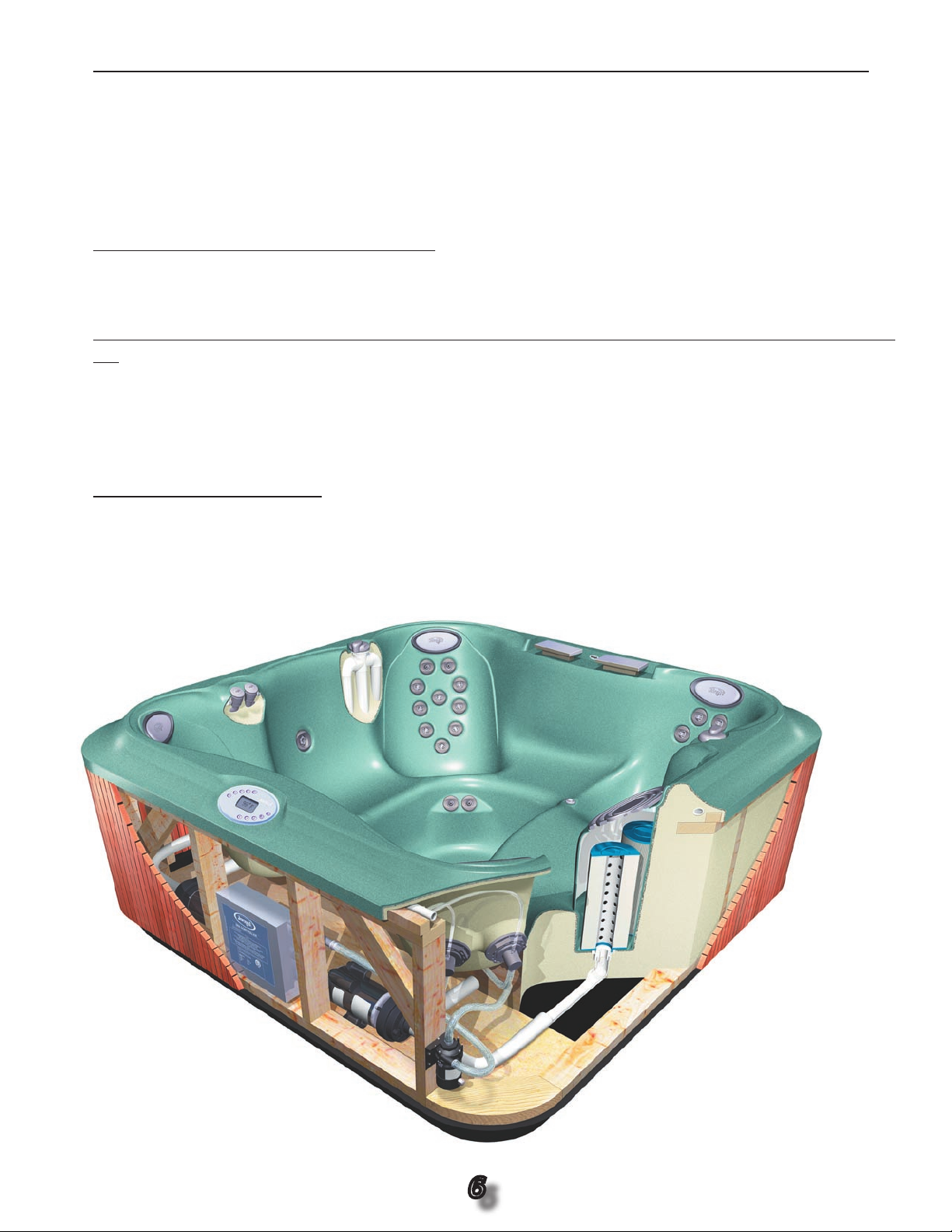
Diverter Valve
Air Controls
Topside Control Panel
Pump #2
Load Box
Pump #1
Circulation Pump
Jets
Remote Panel
Waterfalls
Pillow
Filters
Wood Skirt
Fully Foamed
Removable Pan
Question the homeowner to determine, if possible, what speci c component is not functioning.
•
Use the map of the spa (see below); become familiar with the components and their names. This
will also help when speaking to technical service.
•
Keep the Owner’s manuals in an accessible place.
•
Know the difference between the spa’s components and how they perform when utilized in the spa.
Example: An air control will induce air into the plumbing of the jet, increase the ow of water and
make the jet more powerful.
5.
Ask what is showing on the control panel.
•
Are there any error messages? Ask the customer to speci cally describe the topside control panel
readout, if any.
6.
Determine if the error message is the result of a safety feature or if a service call needs to be set
up.
•
“Cool” and/or “Ice” are generally the result of a spa that has just been lled or re lled and doesn’t
require any action on the part of the homeowner or the technician.
•
Know how the ltration system works, what its defaults are, when it comes on and if there are any
automatic times that it will come on during each day. Know the symptoms!
7.
Setting up the appointment.
•
Make sure you verify the name, address, phone number and where the customer can be reached
if not at home.
•
Ask if there is access to the spa if the owner is not going to be present.
•
Ask about anything that may bar your access to the spa such as locked gates, locked electrical
boxes, vicious dogs, etc.
Spa Map
6
Page 7

8.
Make Sure there is access to the main breaker and GFCI, and ask the homeowner to disconnect
if possible before you arrive at their home.
Use the home service visit as an opportunity to sell aftermarket items such as chemicals, towels,
9.
etc.
10.
Educate your staff regarding chemicals that are important for optimal use and longevity of the spa
components.
•
Chemical misuse is not covered under the terms of the warranty.
Know what to recommend when the customer complains that they cannot get their chemicals
11.
properly balanced. This is not a service call covered by the warranty or a problem that involves the
manufacturer.
•
All spas are used differently: heavy or light bather loads, adults only, the whole family, bromine or
chlorine, etc.
12.
Does the customer know how to properly clean the lter and that the spa needs to be disabled
when doing so?
•
Suggest a second lter to the customer if the original lter needs to be soaked in a cleaning solution. Have one in your truck!
13.
Find out what chemicals the customer is using. If they have saturated the spa with different kinds
of chemicals, sometimes it is best to empty the spa and start all over.
BENEFITS YOU WILL RECOGNIZE
•
A satis ed customer is one who will continue to call upon you for business and does
not contact your competitors.
•
Educating your staff will increase their value and allow you to focus on real service
issues.
•
Being properly prepared will increase your productivity and permit you to enjoy a
weekend once in a while.
Bottom Line: If you change the way you approach your customer, you’ll be putting
•
more money in your pocket.
7
Page 8

1.5 Preparing For A Service Call
1.
Know what each call is asking of you; determine whether or not the extent of service can be handled with a simple phone call or if it requires a visit.
•
Determine whether the call is warranty or non warranty. Make sure the customer is aware that the
manufacturer will not cover out-of-warranty service.
•
If you plan to charge the customer for travel expenses, make sure that they are aware of the costs
before you show up.
2.
Make sure all of your testing devices are functioning properly and extra batteries are on hand.
•
Always bring a meter; when calling technical support, please ensure that you have all of the
pertinent information, such as the spa’s serial number, model number, the system you are
working on, etc.
3.
Prepare your route so you may complete the maximum number of service calls each day.
•
A map book or a large map of your service area will greatly increase your ef ciency.
4.
Bring all the tools needed to properly perform service calls.
•
Always have your vehicle properly stocked with replacement parts.
•
Have a sump pump available for draining purposes; emptying a spa from the drain line takes a lot
of your time, which we know is extremely valuable.
5.
Properly prepare for the day’s service calls.
•
When reviewing your calls, think of every possible component and tool that you may need. For
example, if there is a heating problem or the heater doesn’t come on, think of all the components
that include anything to do with a heat call, such as the temperature sensor, circulation pump, main
pump, ow or pressure switch, lter, circuit board, heater, etc.
•
Prepare for the worst possible scenario and plan to be able to satisfy the subsequent problems
that may arise.
6.
Dress appropriately. Although this is one job where shorts are acceptable, to maintain your credibility as a professional, leave the half shirts and shirts with derogatory or obscene comments at
home.
•
Finish your cigarette before speaking with the spa owner and remember - no drugs or alcohol!
7.
Be on time for your appointments. If you are going to be late or can’t make the appointment, call
the customer to inform them of what’s happening.
•
Call your of ce and ask them to call the people on your schedule to tell them you are running
late.
8.
Always support the product that you service.
•
Do not berate the product in front of the homeowner. It is essential to maintain the integrity
and reputation of the product, and berating the product may affect your credibility as an authorized
service professional.
•
If you feel there is a problem that needs special attention, call us or complete a quality alert. Remember, this is a partnership between you and the manufacturer - we want to provide the best
quality product possible, with your business providing the best service possible!
8
Page 9

9.
Make professional repairs.
•
Putting bondo, underwater epoxy, silicone or any other product to x cracked or leaking plumbing
will not adequately correct the problem and will most likely result in a return visit. Replace the component or come back and do it for free!
•
Make repairs look as good as or better then when you started.
10.
Make sure you leave the customer’s home as clean as you found it.
•
Most customers don’t mind if you are having lunch in their backyard, as long as you remove the
evidence! Make sure to pick up any trash that you may have generated through repairs as well as
break times, lunch, etc.
11.
Leave a work order with the customer explaining what you found to be the problem and how you
corrected it.
•
Make sure the customer understands the work order.
12.
Suggest to the customer any improvements they can make in maintaining their spa.
13.
Recommend replacement lters or a new cover if there is a need for one. A spa vac is an easy sell
once you demonstrate it to the customer.
14.
Always carry a box of lters and a box of the basic chemicals; once you have nished the service,
politely ask if they need any chemicals or a new lter. Drop off chemicals in a sealed box if they
have ordered them when they made their service appointment.
1.6 Before Calling Technical Support
Make sure you have followed the STA and lled out a “Troubleshooting Data Collection Form” (see example on page 61). Have the STA manual and the Troubleshooting Data Worksheet near the telephone. Technical Support can help you
best if these things become the communications tools for the phone call.
1.7 Before Leaving The Customer
Even if you don’t have to ll out a Troubleshooting Data Collection Form, please do so. If this is a warranty repair, the information will be needed when your of ce lls out the “Returned Goods/Labor Tag”.
In any case, it will help you spot trouble before it happens. Pumps burn up if voltage at the hot tub is
too low. Circuit breakers trip if heaters and motors draw too much current (Amps). Wires overheat and
connections burn if wire size is too small or push-on connectors are loose. Call backs cause cost of
service to increase!
9
Page 10

1.8 Satisfying The Customer
Most customers do not care what work you have done or what parts you
have replaced, but they always care whether or not their problem goes away.
When you are done, show them that their problem is gone. If they ask how you
did it, take a few minutes to explain. Show them the bad part(s) and explain or
show why it is bad.
Develop the habit of examining the hot tub’s you service. Compliment customers on the things
•
they are doing right. Tell them how their care and attention can stop trouble before it starts.
Mention if you noticed any adverse conditions, especially if the hot tub is under warranty or con-
•
tract, that could lead to failure. Can the customer correct the problem? Would they like you to correct
it? Can you recommend someone? Would they like an estimate?
Think of yourself and the customer as a “team” trying to keep the product up and running as cost-
•
effective and time-ef cient as possible. That’s good for the customer, and it’s good for your business.
10
Page 11
2.0 Electro Static Discharge
J
1
T
E
M
P
/H
I
-L
I
M
I
T
F
L
O
W
S
W
1
2
3
4
5
6
JP1
7
8
J
4
N
N
N
N
N
L
L
L
L
L
L
Spa Light
Ozone
Circ Pump
Pump
1
Pump
2
F
1
Rev. 3.53
2.1 ESD - What Is It? What Does It Do?
Static electricity is always being generated around us, even at those times
when we no longer get zapped after walking across a rug and touching something.
Like all state-of-the-art circuit boards, the hot tub’s circuit board can be damaged by unnoticed static electricity. Damaged is the key word. Sometimes a
board which has been subjected to ESD will fail immediately upon being put
back into service. Usually a board will operate for a few days, or months, then fail.
•
If the hot tub runs only a few days, the customer thinks you provided poor service.
•
If the hot tub runs only a few months, the customer thinks the circuit board was a low quality
product.
•
The customer loses use of the hot tub. You lose money because you must go back to make it
right. Jacuzzi Premium loses its reputation for quality.
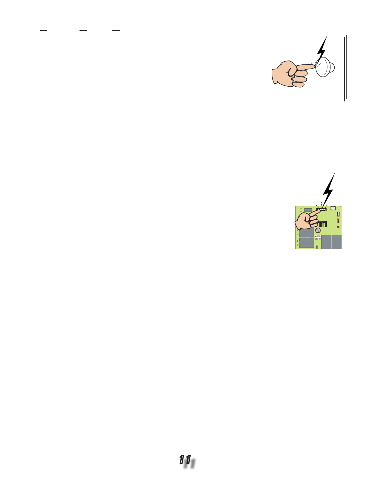
2.2 Avoiding ESD Damage
We can’t prevent static charges from building up within us as we go about our jobs, so
we must do three things to protect circuit boards from getting zapped:
Never transport or ship circuit boards - good boards or bad boards - except in
1.
the static protective bags.
Never remove the board from the static protective bag unless you are ready to
2.
install it in the hot tub.
After removing the bad board from the hot tub, A) lay it on the ground, B) remove
3.
the replacement board from the static protective bag, C) lay the replacement board
on the ground, D) place the bad board in the bag from which you removed the replacement board, E) return bad board(s) to Jacuzzi Premium in undamaged sealed static protective
bags.
2.3 What About Wrist Straps And Special Mats?
The purpose of these devices is to keep the technician, the work surface and the circuit board at the same
electrical potential, and drain into ground any static charges which might build up. Proper use of the wrist
strap and special mat guarantees maximum protection against ESD damage.
2.4 Must Wrist Straps And Mats Be Used When Replacing A Circuit Board?
No, if you keep the spare board in the protective bag during transport and you observe a few simple techniques during replacement.
The possibility of ESD damage to the circuit board during replacement will be minimal because of the hot
tub’s design and the way you normally work on it. Touching the ground lug will drain all built-up static charges
from your body much like a wrist strap would. Laying the bad board on the ground will tend to keep it neutral.
Touching a nger to the grounding lug immediately before removing the good board from the bag will drain
charges built up by the rustling of your clothes. Laying the good board on the ground after removing it from
the bag will tend to keep it neutral. Another quick touch of the grounding lug before picking up the bad board
will drain built up charges. Slipping the bad board into the protective bag will allow it to be transported safely.
Another quick touch of the grounding lug before picking up the good board will again drain any charges built
up. In the process of installing the replacement board, you and the board will be grounded to the load box
or grounding lug, draining off charges you may build up during installation.
11
Page 12

3.0 Main System Speci cations J-345
Dimensions ............................... 84” x 84” x 36” (213cm x 213cm x
92cm)
Dry Weight ................................ 882 lbs (400kg)
Filled Weight ............................. 3,611 lbs (1,638kg)
Water Capacity (Avg. Fill) ........ 336 US gallons (1,272 Liters)
Electronic Controls .................. Solid State Electronic Controls with LED
Readout, Programmable Temperature,
Filtration, and Heat Cycles
Pump 1 ...................................... 2-Speed, 4.2hp brake, 2.5hp continuous
Pump 2 ...................................... 1-Speed, 4.2hp brake, 2.5hp continuous
Pump 3 ...................................... N/A
Circulation Pump ......................Yes
Total PowerPro Jets ................. 25
Maxx PowerPro (MX) ................5
PowerPro (LX) ...........................4
Mini PowerPro (FX) .................. 16
Micro PowerPro (SX) ................N/A
Jet Selectors ............................. 2
Air Controls ...............................Four, On / Off Pushbutton Type
Total Foot Jet Therapy ............. 2
Water Management System .....Two 60ft2 Filter Cartridges; Filter 1 on 24-Hour Circulation Pump; Filter 2
on 2-Speed Pump 1; Ready for optional CD Ozone Generator (Built-in
Ozone Dispersion Chamber Included in Spa)
Lighting ..................................... One Underwater with Two Colored Lenses
Cabinet ...................................... Redwood/Cedar with No Stain; Optional UV Resistant
Synthetic Plastic Cabinet with Embossed Red or Gray Wood Grain
Acrylic Colors ........................... Textured Bluegrass, Jade, Marine, Onyx, Sahara, or Sand; Marbled
Emerald, Platinum, or Sapphire; Solid Azure or Silver
Headrests .................................. 4
Waterfall .................................... Includes Flow Rate / On-Off Adjustment; Powered by Pump 1
Electrical Requirements .......... North American 60Hz Models: 240 VAC @ 30A, 50A, or 60A
Export 50Hz Models: 230-240 VAC @ 35A or 40A, or suitably rated
circuit breaker to comply with local electrical codes. Certain
countries may require dual power inputs; two breakers are required
for this con guration.
Warranty ................................. North American 60Hz Models: 10 Years Shell, 7 Years Shell Surface,
5 Years for Plumbing Component Leaks, 5 Years Equipment &
Controls; Export 50Hz Models: 2 Years Plumbing Component Leaks,
2 Years Equipment & Controls
Seating Capacity .................... 4 - 5
Audio System (Optional) ....... AM/FM/CD Stereo Receiver with Dual Pop-Up Speakers
Dimensions/Speci cations are Subject to Change Without Notice
12
Page 13
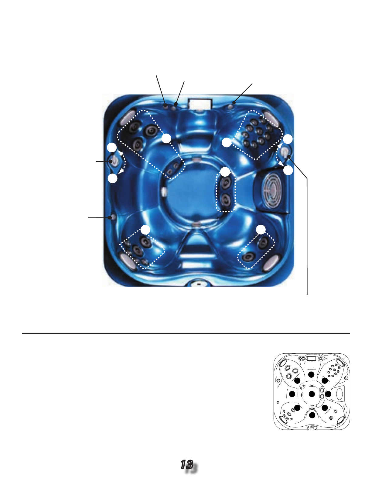
Jet Selector / Air Control Operation Diagram
C
D
A
Jet Selector 2:
Directs Jet Pump 2
Output Between
Jet Groups C or D.
Air Control 1:
Opens / Closes
Air Inlet to Jet
Group A
Air Control 2:
Opens / Closes
Air Inlet to Jet
Group
C
Air Control 4:
Opens / Closes
Air Inlet to Jet
Group D
Jet Selector 1:
Directs Jet Pump 1
Output Between Jet
Groups A or B.
Air Control 3:
Opens / Closes
Air Inlet to Jet
Group
B
D
B
A
C
B
D
E
D
C
B
A
H
I
G
F
A = 25.50” (64.8cm) F = 19.75” (50.2cm) Listed Dimensions
B = 24.00” (60.1cm) G = 27.00” (58.6cm) Represent Distance from
C = 28.50” (72.4cm) H = 25.75” (65.4cm) Top of Acrylic to Lowest
D = 23.00” (58.4cm) I = 34.00” (86.4cm) Point in Seat.
E = 27.50” (69.9cm)
Seat Depths
Dimensions/Speci cations Subject to Change Without Notice
13
Page 14

3.1 Main System Speci cations J-335
Dimensions ............................... 84” x 84” x 36” (213cm x 213cm x
91cm)
Dry Weight ................................ 781 lbs (354kg)
Filled Weight ............................. 3,752 lbs (1,702kg)
Water Capacity (Avg. Fill) ........ 358 US gallons (1,355 Liters)
Electronic Controls .................. Solid State Electronic Controls with LED
Readout, Programmable Temperature,
Filtration, and Heat Cycles
Pump 1 ...................................... 2-Speed, 4.2hp brake, 2.5hp continuous
Pump 2 ...................................... N/A
Pump 3 ...................................... N/A
Circulation Pump ......................Yes
Total PowerPro Jets ................. 24
Maxx PowerPro (MX) ................N/A
PowerPro (LX) ...........................4
Mini PowerPro (FX) .................. 18
Micro PowerPro (SX) ................2
Jet Selectors ............................. 1
Air Controls ...............................Three, On / Off Pushbutton Type
Total Foot Jet Therapy ............. 2
Water Management System .....Two 60ft2 Filter Cartridges; Filter 1 on 24-Hour Circulation Pump; Filter 2
on 2-Speed Pump 1; Ready for optional CD Ozone Generator (Built-in
Ozone Dispersion Chamber Included in Spa)
Lighting ..................................... One Underwater with Two Colored Lenses
Cabinet ...................................... Redwood/Cedar with No Stain; Optional UV Resistant
Synthetic Plastic Cabinet with Embossed Red or Gray Wood Grain
Acrylic Colors ........................... Textured Bluegrass, Jade, Marine, Onyx, Sahara, or Sand; Marbled
Emerald, Platinum, or Sapphire; Solid Azure or Silver
Headrests .................................. 4
Waterfall .................................... Includes Flow Rate / On-Off Adjustment; Powered by Pump 1
Electrical Requirements .......... North American 60Hz Models: 240 VAC @ 30A or 50A
Export 50Hz Models: 230-240 VAC @ 35A or 40A, or suitably rated
circuit breaker to comply with local electrical codes. Certain
countries may require dual power inputs; two breakers are required
for this con guration.
Warranty ................................. North American 60Hz Models: 10 Years Shell, 7 Years Shell Surface,
5 Years for Plumbing Component Leaks, 5 Years Equipment &
Controls; Export 50Hz Models: 2 Years Plumbing Component Leaks,
2 Years Equipment & Controls
Seating Capacity .................... 5
Audio System (Optional) ....... AM/FM/CD Stereo Receiver with Dual Pop-Up Speakers
Dimensions/Speci cations are Subject to Change Without Notice
14
Page 15
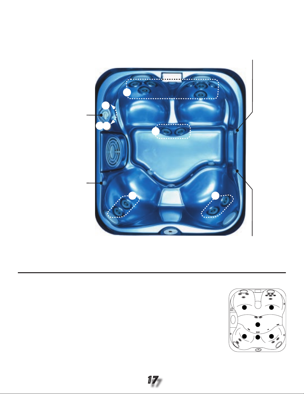
Jet Selector / Air Control Operation Diagram
C
Air Control 2:
Opens / Closes
Air Inlet to All
Lounge Jets A
Jet Selector:
Directs Jet Pump
Output Between Jet
Groups A&B or C.
Air Control 1:
Opens / Closes
Air Inlet to Jet
Group
C
Air Control 3:
Opens / Closes
Air Inlet to Jet
Group
B
A
B
B
B
C
A
E
D
C
B
A
H
G
F
A = 26.50” (67.3cm) F = 19.75” (50.2cm) Listed Dimensions
B = 24.00” (60.1cm) G = 27.00” (68.6cm) Represent Distance from
C = 28.75” (73.0cm) H = 34.00” (86.4cm) Top of Acrylic to Lowest
D = 23.00” (58.4cm) Point in Seat.
E = 27.50” (69.9cm)
Seat Depths
Dimensions/Speci cations Subject to Change Without Notice
15
Page 16

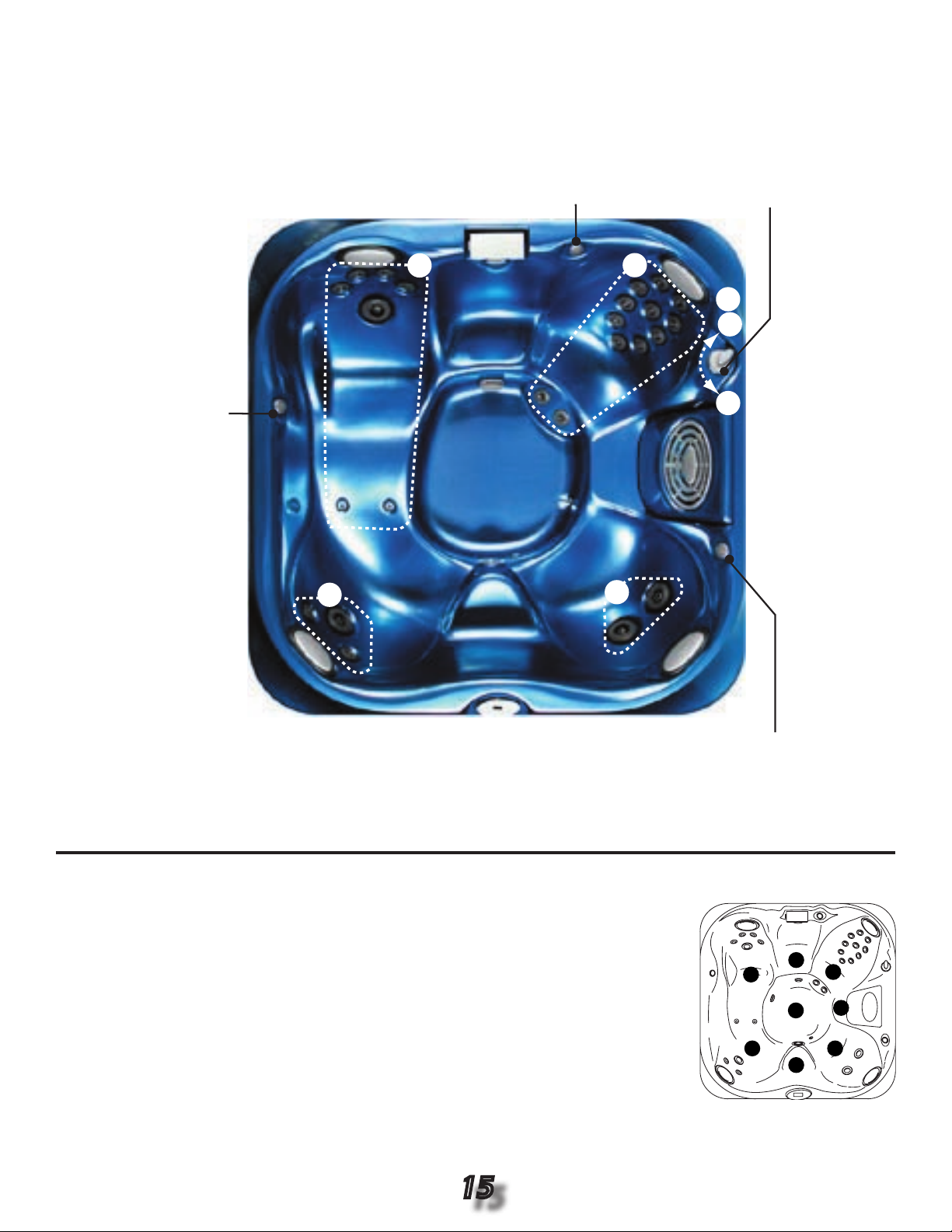
3.2 Main System Speci cations J-325
Dimensions ............................... 84” x 76” x 34” (213cm x 193cm x
86cm)
Dry Weight ................................ 738 lbs (335kg)
Filled Weight ............................. 3,386 lbs (1,536kg)
Water Capacity (Avg. Fill) ........ 320 US gallons (1,211 Liters)
Electronic Controls .................. Solid State Electronic Controls with LED
Readout, Programmable Temperature,
Filtration, and Heat Cycles
Pump 1 ...................................... 2-Speed, 2.0hp brake, 1.5hp continuous
Pump 2 ...................................... N/A
Pump 3 ...................................... N/A
Circulation Pump ......................Yes
Total PowerPro Jets ................. 15
Maxx PowerPro (MX) ................N/A
PowerPro (LX) ...........................11
Mini PowerPro (FX) .................. 4
Micro PowerPro (SX) ................N/A
Jet Selectors ............................. 1
Air Controls ...............................Three, On / Off Pushbutton Type
Total Foot Jet Therapy ............. 2
Water Management System .....Two 60ft2 Filter Cartridges; Filter 1 on 24-Hour Circulation Pump; Filter 2
on 2-Speed Pump 1; Ready for optional CD Ozone Generator (Built-in
Ozone Dispersion Chamber Included in Spa)
Lighting ..................................... One Underwater with Two Colored Lenses
Cabinet ...................................... Redwood/Cedar with No Stain; Optional UV Resistant
Synthetic Plastic Cabinet with Embossed Red or Gray Wood Grain
Acrylic Colors ........................... Textured Bluegrass, Jade, Marine, Onyx, Sahara, or Sand; Marbled
Emerald, Platinum, or Sapphire; Solid Azure or Silver
Headrests .................................. 4
Waterfall .................................... Includes Flow Rate / On-Off Adjustment; Powered by Pump 1
Electrical Requirements .......... North American 60Hz Models: 120 VAC @ 15A or 240 VAC @ 30A or
40A, Export 50Hz Models: 230-240 VAC @ 35A or 40A, or suitably
rated circuit breaker to comply with local electrical codes. Certain
countries may require dual power inputs; two breakers are required
for this con guration.
Warranty ................................. North American 60Hz Models: 10 Years Shell, 7 Years Shell Surface,
5 Years for Plumbing Component Leaks, 5 Years Equipment &
Controls; Export 50Hz Models: 2 Years Plumbing Component Leaks,
2 Years Equipment & Controls
Seating Capacity .................... 4
Audio System (Optional) ....... N/A
Dimensions/Speci cations are Subject to Change Without Notice
16
Page 17
Jet Selector / Air Control Operation Diagram
A
Jet Selector:
Directs Jet Pump
Output Between
Jet Groups A or
B&C
Air Control 3:
Opens / Closes
Air Inlet to Jet
Group C
Air Control 1:
Opens / Closes
Air Inlet to Jet
Group
A
Air Control 2:
Opens / Closes
Air Inlet to Jet
Group
B
B
A
B
C
B
C
E
F
D
C
B
A
A = 27.00” (68.6cm) F = 31.25” (79.4cm) Listed Dimensions
B = 27.25” (69.2cm) Represent Distance from
C = 25.75” (65.4cm) Top of Acrylic to Lowest
D = 21.50” (54.6cm) Point in Seat.
E = 28.00” (71.1cm)
Seat Depths
Dimensions/Speci cations Subject to Change Without Notice
17
Page 18
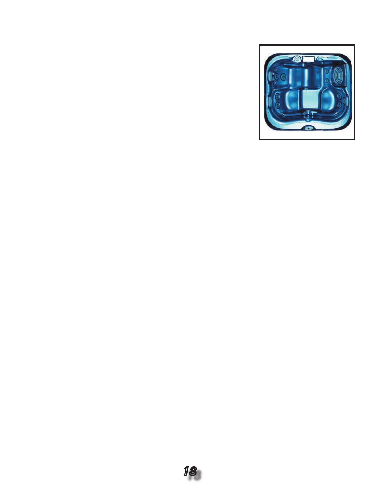
3.3 Main System Speci cations J-315
Dimensions ............................... 76” x 66” x 32” (193cm x 168cm x
81cm)
Dry Weight ................................ 640 lbs (290kg)
Filled Weight ............................. 2,283 lbs (1036kg)
Water Capacity (Avg. Fill) ........ 200 US gallons (757 Liters)
Electronic Controls .................. Solid State Electronic Controls with LED
Readout, Programmable Temperature,
Filtration, and Heat Cycles
Pump 1 ...................................... 2-Speed, 2.0hp brake, 1.5hp continuous
Pump 2 ...................................... N/A
Pump 3 ...................................... N/A
Circulation Pump ......................Yes
Total PowerPro Jets ................. 13
Maxx PowerPro (MX) ................N/A
PowerPro (LX) ...........................7
Mini PowerPro (FX) .................. 6
Micro PowerPro (SX) ................N/A
Jet Selectors ............................. 1
Air Controls ...............................Two, On / Off Pushbutton Type
Total Foot Jet Therapy ............. 2
Water Management System .....Two 60ft2 Filter Cartridges; Filter 1 on 24-Hour Circulation Pump; Filter 2
on 2-Speed Pump 1; Ready for optional CD Ozone Generator (Built-in
Ozone Dispersion Chamber Included in Spa)
Lighting ..................................... One Underwater with Two Colored Lenses
Cabinet ...................................... Redwood/Cedar with No Stain; Optional UV Resistant
Synthetic Plastic Cabinet with Embossed Red or Gray Wood Grain
Acrylic Colors ........................... Textured Bluegrass, Jade, Marine, Onyx, Sahara, or Sand; Marbled
Emerald, Platinum, or Sapphire; Solid Azure or Silver
Headrests .................................. 3
Waterfall .................................... Includes Flow Rate / On-Off Adjustment; Powered by Pump 1
Electrical Requirements .......... North American 60Hz Models: 120 VAC @ 15A or 240 VAC @ 30A or
40A, Export 50Hz Models: 230-240 VAC @ 35A or 40A, or suitably
rated circuit breaker to comply with local electrical codes. Certain
countries may require dual power inputs; two breakers are required
for this con guration.
Warranty ................................. North American 60Hz Models: 10 Years Shell, 7 Years Shell Surface,
5 Years for Plumbing Component Leaks, 5 Years Equipment &
Controls; Export 50Hz Models: 2 Years Plumbing Component Leaks,
2 Years Equipment & Controls
Seating Capacity .................... 3
Audio System (Optional) ....... N/A
Dimensions/Speci cations are Subject to Change Without Notice
18
Page 19
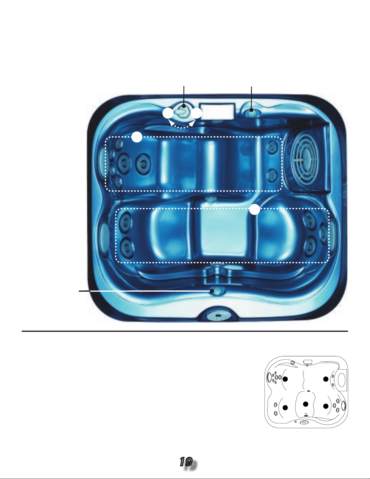
Jet Selector / Air Control Operation Diagram
B
Jet Selector:
Directs Jet Pump
Output Between
Jet Groups A or
B
Air Control 2:
Opens / Closes
Air Inlet to Jet
Group B
Air Control 1:
Opens / Closes
Air Inlet to Jet
Group
A
A
A
B
E
D
C
B
A
Seat Depths
A = 26.50” (67.3cm) Listed Dimensions
B = 28.00” (71.1cm) Represent Distance from
C = 27.00” (68.6cm) Top of Acrylic to Lowest
D = 28.00” (71.1cm) Point in Seat.
E = 27.75” (70.5cm)
Dimensions/Speci cations Subject to Change Without Notice
19
Page 20

4.0 Main Control Panel Functions
104
A
B
C
D
E
F
G
Panel Functions:
Heat Indicator: Lit when heater is on.
A.
Warmer Button: Increases water tempera-
B.
ture setpoint.
Cooler Button: Decreases water tempera-
C.
ture setpoint.
LED Display: Can display current water
D.
temperature (default display*), water temperature setpoint, selected ltration mode,
and error messages.
E.
Light Button: Turns underwater light on
and off.
Jets 1 Button: Turns pump 1 on and off as follows: Press once for low speed; a second time for
F.
high speed; a third time to turn off.
Jets 2 Button (J-345 only): turns pump 2 on and off as follows: Press once for high speed; a sec-
G.
ond time to turn off.
Operation Details:
• Temperature Adjustment: 65 to 104ºF (18 to 40ºC). Factory setting is 100ºF (38ºC).
• Underwater Light Operation: The light runs for 1 hour, then shuts off for increased bulb life.
• Jet Buttons Operations: The jets run for 20 minutes after activated then turn off automatically to con-
serve energy. Simply press a Jet Button to continue operation for an additional 20 minutes.
*Disply shown for example purposes only,
actual water temperature display will vary..
4.1 Setting Filter Cycle Start Time
Two methods for setting the lter cycle start time are possible:
• Turn power on to the hot tub two minutes prior to the desired lter cycle start time, or
• Press and hold both the Warmer and Cooler Buttons at the same time, then press and hold the Jet 1
Button to reset the control panel and start the power up sequence. During the power up sequence, the
previously set lter cycle setting and temperature setpoint will be maintained. To select another lter
cycle at this time, see section 4.2 below. The selected lter cycle will start approximately two minutes
after the power up sequence ends.
Example: If you desire your rst lter cycle to begin at 10:00am, perform either of the above steps at 9:
58am. Filter cycle start time may vary slightly from the setpoint.
4.2 Programming Filter Cycles
Proper ltration is an important key to maintaining the clarity of your hot tubs water. The hot tubs ltration system is designed for unsurpassed effectiveness at removing debris and suspended particles
from the water anytime the water is circulated by the pump.
To select a pre-programmed lter cycle or lockout mode, press and hold both the Warmer and Cooler
Buttons at the same time, then release. Then press either the Warmer or Cooler Buttons to select either
lter mode FØ through L2.
20
Page 21

Standard Filtration Modes FØ - F3
Heating in either of these modes (FØ - F3) is automatically controlled by the water temperature. If the
hot tub water drops 2ºF (1.2ºC) below the temperature setpoint, the heater will turn on with the circulation pump. Both remain on until the water temperature rises to the temperature setpoint, then the heater
will turn off. Refer to the options below:
3.53 Revision
No lter cycles.
FØ
F1
4 hours of ltration a day (2 hour cycle every 12 hours)
6 hours of ltration a day (2 hour cycle every 8 hours)
F2
F3
8 hours of ltration a day (2 hour cycle every 6 hours)
3.54+ Revision
No lter cycles, 5 minute blowout cycle once a day, every 24 hours from the time of power up.
FØ
F1
1 hour of ltration a day (1/2 hour cycle every 12 hours)
1 1/2 hours of ltration a day (1/2 hour cycle every 8 hours)
F2
F3
2 hours of ltration a day (1/2 hour cycle every 6 hours)
Economy Filtration Modes F4 - F6
In any economy mode (F4 - F6), the control panel’s digital timer circuit determines when each lter
cycle takes place. The heater will only operate while a lter cycle is running. The heater will not operate
when either Jets button is pressed to manually cancel an active lter cycle or to activate the main jet
pump between lter cycles. Refer to the options below:
3.53 Revision
F4
4 hours of ltration a day (2 hour cycle every 12 hours)
F5
6 hours of ltration a day (2 hour cycle every 8 hours)
F6
8 hours of ltration a day (2 hour cycle every 6 hours)
3.54+ Revision
F4
1 hour of ltration a day (1/2 hour cycle every 12 hours)
F5
1 1/2 hours of ltration a day (1/2 hour cycle every 8 hours)
F6
2 hours of ltration a day (1/2 hour cycle every 6 hours)
Lockout Modes L1 - L2
Additional modes (L1 - L2) are special modes designed for servicing/cleaning. Refer to the options
below:
L1L2Lock Out (disables all hot tub functions to permit lter cleaning or other maintenance) - If the hot
tub is heating when the system is put into lockout mode, the heater will immediately shut off and
the circulation pump will cycle water for 30 seconds to cool the heater element, then shut off.
Lock Mode (disables the jets and light buttons to prevent unauthorized use of the hot tub) - The
lter cycles and heater will continue to operate as programmed in this mode. Example: The “F3”
lter cycle was enabled prior to choosing the lock mode. The hot tub continues to perform lter
cycle “F3” until lock mode is cancelled, allowing another lter cycle to be selected.
The temperature display ashes when either Lock Out Mode is enabled.
21
Page 22

4.3 Aftermarket Ozone Facts
An aftermarket ozonator can be installed on all 2002+ models. A mazzei injector is required on all models.
Ozone System Speci cations
• Circulation pump runs 24 hours
• Ozonator runs 24 hours
• The ozonator shuts off when a Jets Button is pressed. The ozonator will resume operation approxi-
mately 5 minutes after the jets are turned off intentionally or automatically. The ozonator also shuts off
if the hot tub goes into “Summer Logic.” See section 5.6 (page 23).
Refer to section 8.13 (page 44) for troubleshooting details.
5.0 Additional Control Panel Functions
5.1 Temperature Setting
To enable the set temperature display:
Press WARMER or COOLER button while the current water temperature is dis-
1.
played. The current temperature setpoint appears.
Press WARMER or COOLER button within 3 seconds to increase or decrease set
2.
temperature by 1º per button press.
3.
After 3 seconds of keypad inactivity the display will return to the actual water temperature and the
new temperature setting will be maintained.
Use Warmer/
Cooler Buttons
5.2 Selecting Jets Speed
To select jet speeds:
Press JET 1 button once for low speed; a second time for high speed; a third time
1.
to turn off.
J-345 only; Press JET 2 button once for high speed; a second time to turn off.
2.
Use JET 1/
JET 2 Buttons
Note: Anytime a pump has been manually turned on by selecting either JET button, it will automatically
turn off after approximately 20 minutes. If at this time you desire more jet operation, simply turn the jet
pump back on.
5.3 Underwater Light Operation
Press the LIGHT Button once to turn on; a second time to turn off.
Note: Anytime the light has been manually turned on, it will automatically turn off after
approximately 1 hour to maximize bulb life. If at this time you desire more light opera-
Use Light
Button
tion, simply turn the light back on.
5.4 Lock/Unlock Control Panel
The control panel temperature display ashes when Lock Mode is active. Lock Mode
disables the jets and underwater light to prevent unauthorized use of the hot tub. This
mode is selected in the lter cycle selection menu. When selected, both lter cycles
and heater will operate as programmed. See sections 4.2 (page 20).
Display is
Flashing
22
Page 23

5.5 Lock Out Mode
N
J
1
T
E
M
P
/H
I
-L
I
M
I
T
F
L
O
W
S
W
1
2
3
4
5
6
JP1
7
8
J
4
N
N
N
N
N
N
N
L
L
L
L
L
L
L
L
L
Spa Light
Ozone
Circ Pump
Pump
1
Pump
2
Red Black
Heater In
Heater Ou
t
F
1
Rev. 3.53
1
2
3
4
5
6
JP1
7
8
The control panel temperature display ashes when the Lock Out Mode is active. Lock
Out Mode disables all hot tub functions to permit lter cleaning. If the hot tub is heating
when lockout mode is selected, the heater will immediately turn off and the circulation
pump will cycle water for 30 seconds to cool the heater element, then turn off. See
Display is
Flashing
section 4.2 (page 20).
5.6 Summer Logic
When the water temperature in the hot tub rises 2ºF (1ºC) above the set temperature
setpoint. the hot tub goes into “Summer Logic.” When this happens, the circulation
pump automatically turns off to prevent additional heat build up from the pump that
would eventually create an overheat condition. The circulation pump, main pump and
Display is
Flashing
aftermarket ozone (when installed) will remain off until the water temperature cools to
the set temperature, then reactivate as programmed. This setting is not user-pro-
grammable.
Note: Summer Logic does not take effect until the hot tub’s water reaches 95ºF (35ºC) or higher.
6.0 Understanding Circuit Board Pin Assignments
6.1 Circuit Board Jumpers
All ProTech LED circuit boards can be con gured for either 15/30A or 50A 240 VAC operation (J-340
can be con gured for 60A with 3.54 Revision Chip). Refer to the jumper pin table and circuit board diagram below for speci c details:
2002+ ProTech LED Circuit Boards
Pins 1-2:
Pins 1-2:
Jumper OFF
Jumper ON
- Enables 50A Logic; Allows heater to run with 1 pump in high speed.
- Enables 15/30A Logic; Forces heater off when any jet pump is in high
speed. Overrides 50 or 60A Logic.
Jumper OFF
Jumper ON
Jumper OFF
Jumper OFF
Jumper ON
Jumper OFF
Jumper ON
- Enables 1 Pump Logic.
- Enables 2 Pump Logic; J-340 only.
- Revision 3.53 Circuit Boards; Not used at this time.
- Revision 3.54+ Circuit Boards; Enables 50A Logic.
- Revision 3.54+ Circuit Boards; Enables 60A Logic, J-345 only.
- Enables Fahrenheit (ºF) temperature display.
- Enables Celsius (ºC) temperature display.
Pins 3-4:
Pins 3-4:
Pins 5-6:
Pins 5-6:
Pins 5-6:
Pins 7-8:
Pins 7-8:
23
Page 24

7.0 Troubleshooting Using The Control Panel
7.1 Control Panel Displays
Complete operating instructions for the control panel can be found in the owner’s manual. The hot tub’s
self-diagnostic control system constantly monitors the hot tub for proper operation. When anything
goes wrong, the control panel displays a message for the user which may result in a service call. Refer
to section 7.3 below for a listing of error messages and probable causes.
7.2 Control Panel Default Display
The control Panel displays the following information during initial start up:
1.
The control panel displays the current software eprom revision, then
2.
The control panel displays “888” and all of the indicator LED’s are lit, permitting visual
inspection of all display segments and indicator lights for proper operation.
3.
After the initial start up sequence ends, the actual water temperature is displayed. If
the water temperature at this time is less than the factory preset temperature setting
of 100ºF (38ºC):
•
The circulation pump and heater will turn on and run until the temperature rises to the factory preset
temperature setting. The heater shuts off and the circulation pump remains on for 24 hour operation.
Approximately two minutes after initial start up, the rst lter cycle begins to operate. The ltration cycle can be modi ed any time after the start up sequence ends. You will be able to select a preprogrammed lter cycle and reset your temperature setpoint at this time (see page 20). Press either
the COOLER or WARMER buttons once at this time to display the current temperature setpoint. You
can change the setpoint by pressing either the COOLER or WARMER buttons within 3 seconds. Each
button press increases or decreases the temperature setpoint by 1º. Three seconds after the setpoint
is set, the display defaults back to the actual water temperature.
7.3 Control Panel Status And Error Messages
Sn1 Nonfunctional Hi-Limit Sensor
Open or shorted hi-limit sensor. Heater is deactivated. Refer to test steps 1-2 below:
Turn off the main breaker to the hot tub. Refer to appendix page 55 for expected hi-limit
1.
sensor resistance/water temperature values.
Remove the hi-limit sensor connector from the circuit board test point 10. Refer to pages 50-51 for
2.
your circuit board con guration. Set your ohmmeter to 100-200k range, then measure resistance
across the hi-limit sensor wires (see page 56). If the sensor tests OK, check the sensor connections.
If the connections are OK, replace the circuit board. If the sensor resistance is incorrect, replace the
hi-limit sensor.
Sn2 Nonfunctional Temperature Sensor
Open or shorted temperature sensor. Heater is deactivated. Refer to test steps 1-2 below:
1.2.Turn off the main breaker to the hot tub. Refer to appendix page 55 for expected temperature sensor resistance/water temperature values.
Remove the temperature sensor connector from the circuit board test point 10. Refer to pages
50-51 for your circuit board con guration. Set your ohmmeter to 100-200k range, then measure
resistance across the temperature sensor wires (see page 56). If the sensor tests OK, check the
sensor connections. If the connections are OK, replace the circuit board. If the sensor resistance is
incorrect, replace the temperature sensor.
24
Page 25

FL1 And FL2 Water Flow Problem
• FL1: The ow switch is not closed when the circulation pump is running. The heater is
deactivated. Proper water ow is inhibited or the ow switch may be obstructed, misaligned
or defective. Refer to troubleshooting steps 1-4 below:
Remove the lter and allow the air to bleed out of the cartridge. Check the lter for trapped air.
1.
Check for the proper water level.
2.
Check for a clogged lter cartridge.
3.
If the problem persists, refer to section 7.4 (page 26) for ow switch testing instructions.
4.
• FL2: The ow switch is closed when the circulation pump is not running. The heater is
deactivated and the pump may or may not turn on. The ow switch is usually defective.
Refer to section 7.4 (page 26) for ow switch testing instructions.
COL Cool Condition
If the water temperature drops 20ºF (11ºC) below the set temperature, the heater will activate to raise the water temperature to within 15ºF (8ºC) of the set temperature. No corrective action is necessary.
ICE Freeze Condition
A potential water freeze condition of 55ºF (13ºC) has been detected. No action is required.
The heater will activate and raise the water temperature to approximately 65ºF (18ºC),
cancelling the “ICE” error message. After the error message is cancelled, the heater will
turn off.
OH High Temperature Condition
The water temperature is above acceptable limits. DO NOT ENTER THE HOT TUB
WATER. The water temperature has reached 112ºF (44ºC) and the low speed pump has
activated to circulate water through the hot tub to cool it down. Refer to test steps 1-4
below:
1.
Verify the actual water temperature with an accurate thermometer. If the actual water temperature
is less than 112ºF (44ºC), proceed to steps 2-4.
2.
Turn off the main breaker to the hot tub. Refer to appendix page 55 for expected hi-limit/temperature
sensor resistance/water temperature values.
3.
Remove the hi-limit sensor connector from the circuit board points 10. Refer to pages 50-51 for your
circuit board con guration. Set your ohmmeter to the 100-200k range, then measure resistance
across the sensor wires (see page 56). If the resistance tests OK, check the wiring harness connections. If the wiring harness connections test OK, replace the circuit board. If the sensor resistance is
incorrect, replace the hi-limit sensor.
4.
Set your ohmmeter to the 100-200k range, then measure resistance across the temperature sensor
wires (see page 56). If the resistance tests Ok, replace the circuit board. If the temperature sensor
resistance is incorrect, replace the temperature sensor.
--- Watchdog
The water temperature has reached 118ºF (48ºC). DO NOT ENTER THE HOT TUB WATER. The entire system is disabled. Refer to test steps 1-4 below:
1. Check the hi-limit and temperature sensor resistance values. Both sensors should measure close in
resistance to each other (e.g. one may be defective and way out of range). Refer to appendix page
55 for expected hi-limit/temperature sensor resistance/water temperature values. If either sensor is
faulty, replace it and recheck the system. If the problem persists, proceed to step 2.
25
Page 26

2.
fig. A
fig. B
Incorrect
Orientation
Correct
Orientation
FLOW
Arrows
aligned
FLOW
Arrows
not
aligned
Open
Continuity 0 ‰
(Pump ON)
Closed
‰
Infinite ‰
(Pump OFF)
‰
Plug in a new control panel. If the problem is corrected, replace the control panel. If the problem
persists, proceed to step 3.
3.
Check the voltage at the transformer secondary. See section A15, page 57, for transformer testing
instructions. If the voltage is bad, replace the transformer. If the voltage is good, proceed to step 4.
Check the circuit board transformer connections. If the connections are loose or oxidized, repair the
4.
connections and retest the system. If the problem persists, replace the circuit board.
7.4 Testing Flow Switch
Verify the ow switch directional arrow is pointing in the direction of ow towards the heater return
1.
tting outlet. If the ow switch orientation is incorrect, loosen or tighten the switch no more than 1/2
turn, being careful not to bottom out the switch in the tting. The switch’s ow arrow must be parallel
to the tee tting as shown ( g. A). Test the system operation. If the condition persists, proceed to
step 2.
Remove the switch from the tting making note of the number of turns (revolutions) it takes to do so.
2.
Visually inspect the switch for debris interference or damage. If debris is present, remove the debris,
then reinstall the switch with the same number of turns as originally installed. Test the sytem. If the
switch is damaged, replace the switch and retest the system. If the condition persists, proceed to
step 3.
Test the switch operation with an ohmmeter (set to 1000-2000k range) for continuity across the
3.
switch terminals. Measure resistance across the switch terminals for in nite resistance with the
magnet arm not touching the switch body ( g. B), and for continuity (Ø ohms) with the magnet arm
touching the switch body ( g. B). If the ow switch tests OK, check the wiring harness. If the wiring
harness tests OK, replace the circuit board.
26
Page 27

8.0 Troubleshooting Without The Control Panel
Replace or reconnect wires
between heater output and
heater element.
Circuit Board Illustrations
A. 2002+ Protech LED Models (Page 50-51)
Replace heater.
Replace Thermal Switch
Is voltage present at heater
input? Test points 4 and 5.
Replace or reconnect wires
between heater input relay
and TB1 (main power
terminal block).
Replace circuit board.
Place thermometer against heater
housing and verify temperature.
Is temperature above 130 F?
Locate thermal switch inside
heater box. Set voltage meter to
500-1000 VAC range. Test
thermal switch by connecting
voltage meter across the
terminals with a heat call present
(see fig. C). If 120 VAC* or 240
VAC exists, the switch is open. If
no voltage exists, the switch is
closed. Is the switch open?
*Convertible J315 and J325
models only
.
Is voltage present at heater
element? Test points 8 and 9.
No
No
No
No
Ye
s
**Call Technical Support
Yes
Yes
Ye
s
Ye
s
Current draw is proof that
heater element is working.
Make sure customer knows
how to use control panel and
heater. Ask about any possible
error messages.
Yes
No
No
Is there current draw? Refer
to section A3 (page 47) for
expected heater current
consumption values.
Check heater element with
clamp-on ammeter around one
of the heater element wires.
Is the heater element’s current
draw within –10% of its listed
value?
Turn up temperature setpoint
to initiate a heat call (must be
in "standard mode" F0-F3; see
page 21). Is voltage present
at the heater output? Test
points 6 and 7.
fig. C
Thermal Switch
Bad
Thermal Switch
Good
VAC
VA
C
Optional Test Method: you can also
remove one wire from either side of switch
and test across its terminals for continuity
.
Infinite =bad switch; 0 =good switch
• Diagnostic Tools for Sections 8.1A - 8.1D: Clamp-on ammeter, voltmeter and ohmmeter.
• Suggested Spare Parts for Sections 8.1A - 8.1D: Circuit board, control panel, temperature sensor,
ow switch, heater assembly, hi-limit, circulation pump. Refer to page 59 for additional information.
8.1A No Heat Or Not Enough Heat
• Symptoms: Circulation pump (heating pump) is moving water, panel heat indicator is lit. water is not
getting hot.
• Con guration: Protech LED system heaters will not operate with both jet pumps (J-345 only) running
in high speed if the circuit board is con gured for 30 or 50 Amp operation. See section 6.1, page 23.
Standard Troubleshooting Approach
Danger: Electrical Shock Hazard Exists!
High Voltage Present On Circuit Board. Use Extreme Caution While Servicing Circuit Board.
27
**Warning: heater temperature may have exceeded 130ºF (54ºC). Inspect heater. Call technical support if visible damage is apparent.
Page 28

8.1B No Heat Or Not Enough Heat
Pull wire off flow
switch. Does the
FL2 error message
go away?
Replace wire.
Turn off power to hot
tub. Test flow switch
with ohmmeter for
continuity across
switch terminals (fig.
D-E). Does meter
read continuity
(0)?
Remove flow switch
and inspect for
debris interference.
Remove debris if
present. Test switch
for continuity (0)
when closed and for
infinite when open
(fig. E). Does switch
operate correctly?
Make sure wire is
not shorted when
installed on switch.
Install switch making
sure flow arrow
points in direction of
flow and switch
doesn’t bottom in
fitting (fig. F). Retest
system.
Is wire shorted?
No No
Ye
s
Ye
s
Ye
s
Yes
No
Replace flow switch.
No
Replace circuit
board.
Fig. D
Infinite
Continuity 0
Fig. E
Infinite
Continuity 0
FLOW
Orientation Orientation
FLOW
Fig. F
Pipe End
View
OK
Arrows not
aligned
Arrows
aligned
Open
Closed
Pump
off
Pump
on
• Symptoms: Circulation pump (heating pump) not turning, panel heat indicator not lit,
panel is ashing FL2.
Standard Troubleshooting Approach
28
Page 29

8.1C No Heat Or Not Enough Heat
Is there correct voltage
coming to the hot tub at
TB1?
240 VAC, +/-10%, or
(120/240 VAC, +/-10%
for J315/J325 models).
Replace circuit
board.
Repair connection.
Call an electrician.
Put hot tub in standard
filtration mode (page
21). Set temperature
high enough to initiate a
heat call. Is voltage ok
from circuit board to
circulation pump?
Test points 16 and 17 for
circulation pump.
No
No
Ye
s
Ye
s
Replace pump.
Yes
No
Is connection OK from
circuit board to pump?
Circuit Board Illustrations
A. 2002+ Protech LED Models (Page 50-51)
• Symptoms: Circulation pump (heating pump) not turning, panel heat indicator not lit,
panel is ashing FL1.
Standard Troubleshooting Approach
Note: Refer to the voltage and current charts on appendix page 46-47 for expected voltage/current readings.
Danger: Electrical Shock Hazard Exists!
High Voltage Present On Circuit Board. Use Extreme Caution While Servicing Circuit Board.
29
Page 30

8.1D No Heat Or Not Enough Heat
No
Verify hot tub is in
standard filtration mode
(page 21). Remove flow
wires from switch.
Increase set temperature
to Initiate a heat call, then
jumper flow switch wires
together (see fig. G).
Does heat indicator
appear and FL1 error
message disappear?
Is the circulation pump
(Heat Pump) moving
water?
Remove flow switch and
inspect for debris
blockage. Remove
blockage or replace
switch. Install flow
switch with arrow
pointing in direction of
flow. Make sure magnet
arm doesn’t bottom out
in fitting (fig. J).
1. Remove filter and
allow air to bleed out
of cartridge.
2. Check for proper
water level.
3. Check for clogged /
excessively dirty
filter
.
4. Is pump moving
water?
No
No
No
Ye
s
Ye
s
Yes
Yes
Ye
s
Remove flow switch
connector from circuit
board at point 11 (fig. H).
Place jumper across
exposed connector pins*.
Does heat indicator
appear and FL1 error
message disappear?
*Lightly scrape contact pins at
point 11 with a razor blade or
sandpaper to remove conformal
coating or oxidation from contact
surface.
Replace circuit board.
Repair or replace flow
sensor cable.
Clean connectors between
flow cable and switch.
See section 8.10 (pg. 42)
Test flow switch with
ohmmeter for continuity (0)
across switch terminals
(fig. I). Does meter read
continuity
(0) with pump on?
No
Danger: Electrical Shock Hazard Exists!
High Voltage Present On Circuit Board. Use Ex
-
treme Caution While Servicing Circuit Board.
fig. G
fig. H
fig. I
Temporarily Jumper
Flow Switch Cable
Wires Together as Shown.
fig. J
FLOW
Incorrect
Orientation
Correct
Orientation
FLOW
Pipe
End View
correct
incorrect
Arrows
not
aligned
Arrows
aligned
Temporarily
Short Pins
with Jumper
#6560-864
Flow
Cable
22
23
Infinite
Continuity 0
Pump off
Pump on
Open
Closed
Jumper
• Symptoms: Circulation pump (heating pump) is turning, panel heat indicator not lit,
panel is ashing FL1.
Standard Troubleshooting Approach
30
Page 31

8.1E No Heat Or Not Enough Heat
Put hot tub in standard
filtration mode (page 21).
Set temperature high
enough to initiate a heat
call. Remove power to hot
tub then plug in a spare
control panel. Turn power
on. Does indicator work
now?
Replace control panel.
No
Ye
s
Call Jacuzzi Premium
Technical Support.
• Symptoms: Circulation pump (heating pump) is turning, panel heat indicator not lit,
panel is not ashing FL1.
Standard Troubleshooting Approach
31
Page 32

8.2 Intermittent Heating
correct
incorrect
As with all intermittent problems, routine measurements and display panel error messages are not
trustworthy. The following procedure will eliminate the most probable causes.
It is important to explain to the customer how dif cult intermittent problems are to locate. You will be doing a series of things to eliminate the problem. Ask the customer to be patient and please cooperate by
calling you back to inform you of the hot tub’s status until the problem is corrected. It might be a good
idea to review this STA with the customer. It may help he or she understand why it might take several
callbacks to effect a repair.
Suspects: circuit board, temperature sensor, control panel, wiring connections, and partial water ow
obstructions.
Diagnostic Tools: Voltmeter, ohmmeter and ammeter.
Suggested Spare Parts (Page 59): Heater, circuit board, temperature sensors, ow switch, control
panel, circulation pump, hi-limit.
Standard Troubleshooting Approach
1.
Check the crimped wire connections to the heater. If burned, replace the heater. Verify that the
heater connections are good on the circuit board. Check the heater resistance, see the current chart
on page 47 for expected heater resistance values.
Check the connections labeled “heater out” on the circuit board (test points 6 & 7). Refer to pages
2.
50-51 for your circuit board con guration. If possible, clean and renew the connections. If a relay is
physically burned at the connections, replace the circuit board.
3.
Check the ow switch for proper and consistant mechanical operation. Observe the mechanical action of the switch. Refer to page 26 for the ow switch testing procedure.
Clean the connections where the panel plugs into the circuit board.
4.
If all of the above items check out, ask the customer if the Sn2 error has ever displayed. If the Sn2
5.
error message has displayed, replace the temperature sensor.
6.
Tell the customer what you have done, that you are not sure that the problem has been xed, and
that you want to be called immediately if the problem returns. Explain what you will do if the problem
returns. Check back with the customer in a few days if you haven’t been contacted.
If the customer calls back, call Jacuzzi Premium Technical Support.
7.
Note: All models use a ‘magnetic reed switch” type of ow switch that
can remain closed or open from debris interference. Removal of the ow
switch for cleaning and inspection will correct most problems. Record the
number of turns it takes to remove the switch from the tting. After cleaning, use the same number of turns to reinstall the switch. DO NOT thread
the switch further than originally installed, or the paddle may stick on the
bottom of the tting.
32
Page 33

8.3 Nothing Works
Things to remember: when a system fails, there is probably one, and only one problem. Verify power to
the hot tub by observing the control panel’s LED display. The control panel will usually display something as long as there is proper power to the hot tub. Check for error messages. Displayed error messages usually indicate the problem.
Diagnostic Tools: Voltmeter.
Suggested Spare Parts (Page 59): Fuses (see appendix page 48), control panel, circuit board.
Nothing Works (Panel Indicator Lit):
1.
Plug in a spare control panel. If it works, replace the control panel.
2.
Remove power from the hot tub. Check the connections on the sensor harness and verify proper
resistance of the temperature and hi-limit sensors (see appendix page 55). Replace the defective
temperature or hi-limit sensor, then test the system.
3.
Check the transformer. See section A15, page 57.
4.
Still no operation? Replace the circuit board.
Nothing Works (Panel Dead):
1.
Check for proper power to the hot tub (see appendix page 46). Check for 240 VAC (120 or 240
VAC for J-315, J-325) at TB1 on the main terminal block. See pages 50-51 for your circuit board
con guration. If the voltage is not 240 VAC (120 or 240 VAC for J-315/J-325) ±10%, consult an
electrician.
2.
Check for power at the transformer secondary. Refer to appendix page 57. If power exists on the
transformer secondary, plug in a spare control panel. Still nothing? Replace the circuit board.
If no power exists at the transformer secondary, check for voltage at the transformer primary. Refer
3.
to appendix page 57. If voltage exists on the primary but is missing on the secondary, replace the
transformer.
No power at the transformer primary indicates either an open 1.5 Amp fuse, 20/30 Amp fuse, or a
4.
loose or disconnected wire. If voltage exists on the primary but is missing from the secondary, replace the transformer. See section A5 (page 48) for speci c fuse details.
8.4 Hot Tub Doesn’t Come On For Filter Cycle
Turn power to the hot tub off and then on to restart the lter cycle program. Does the lter cycle start
approximately two minutes after applying power?
• If yes: the hot tub is functioning properly. Refer to sections 4.1 - 4.2 (page 20) for lter cycle setup
details. Take time to explain the lter cycle selection and operation to your customer. Make sure your
customer understands the lter cycles are selectable, not programmable.
• If no: select an appropriate lter cycle mode within two minutes after applying power. Refer to sec-
tions 4.1 - 4.2 (page 20). If the lter cycle starts within two minutes after setting, no corrective action is
required. If the lter cycle does not start two minutes after setting, replace the circuit board.
33
Page 34

8.5 House Breaker Trips
The hot tub’s current draw will vary depending on how it’s circuit board is jumpered. Jumper options
determine whether multiple functions can operate together.
If the house breaker trips, check the hot tub’s current draw. If the jumpers are properly set and the
current draw is within expected limits, the house breaker or wiring may be defective and need to be
replaced or repaired. The hot tub’s current draw at the breaker represents the sum of all enabled components. Refer to appendix page 47.
If the hot tub’s current draw is high, individual component current measurements must be made to determine which component is pulling excessive current. Refer to appendix page 47. Repair or replace
the component which is drawing excessive current.
8.5A GFCI Tripping
If the GFCI trips, try disconnecting the heater and the pumps from the circuit board one at a time to nd
which component may be causing the GFCI to trip.
When a customer complains of intermittent GFCI tripping, these questions need to be answered before
we start replacing components on the hot tub. 90% of a GFCI’s tripping problems are the direct result
of improper wiring or installation.
1.
Has the GFCI always tripped or has it just recently started tripping?
• Has the hot tub just been installed?
• Electricians are not as smart as they think they are and the owner’s cousin’s nephew who’s a
painter really isn’t a licensed electrician.
• New deliveries cause 90% of all GFCI tripping problems.
• Know what to look for when you approach this problem. Refer to section A9-A11 (pages 50-52).
How was the hot tub delivered?
2.
• Check for visible damage to all hot tub components.
3.
What Brand of GFCI was installed?
• Some brands are known to be more sensitive than others which can cause nuisance tripping.
When does it trip? At the start of a ltration cycle, etc., be speci c.
4.
• The customer needs to provide you with this information. Have them takes notes on when the hot
tub trips. How often does it trip? Be speci c. Intermittent tripping of the GFCI is very hard to pinpoint
if you can’t get speci c information.
What size is the GFCI? 30, 50 or 60 Amp?
5.
What size is the wiring? 8-10 gauge for 30 Amp, 8-6 gauge for 50 Amp, 6 gauge for 60 Amp. All wir-
6.
ing must be done to Local and NEC code.
What kind of wire are they using, copper or aluminum?
7.
• Aluminum wire is not recommended.
34
Page 35

8.
Is the GFCI utilized at the main panel?
• Verify how it is hooked up.
• If you are not licensed to properly change the wiring, show the customer how it should be hooked
up and have them call the electrician. (Improper installation is not a warranty call which once corrected may involve you coming back to replace a component.) If there is a problem with the elec-
trician understanding the correct hook up of the hot tub, have the electrician contact Jacuzzi
Premium Technical Support.
9.
Is the GFCI and wiring dedicated only to the hot tub?
10.
Are there any other devices hooked up to the hot tub; a light, extra outlet, etc.?
11.
How long is the run from the main panel to the hot tub?
• Longer runs require a wire size compatible to that length of the run.
12.
Is there a disconnect or sub-panel in the run?
How is the disconnect hooked up? Be speci c.
13.
• There needs to be FOUR wires (two hots, a neutral, and a ground) at the disconnect for the GFCI
to properly function.
Is this a 3-wire or a 4-wire hook up?
14.
• The J-335, J-345 are all 240 VAC, 3-wire hook ups.
• The J-315, J-325 is a 3-wire when hooked up to 120 VAC, and a 4-wire when hooked up to 240
VAC.
Is there 240 VAC (120 or 240 VAC on J-315-J-325) at the hot tub?
15.
• Refer to the model the customer has purchased and then con rm the hook up using the diagrams
provided in sections A9-A11 on pages 50-52.
How are the wires connected at the GFCI?
16.
• 3-wire, 240 VAC hook ups DO NOT USE A LOAD NEUTRAL OUT OF THE GFCI TO THE HOT
TUB.
Is the neutral wire hooked up on the GFCI?
17.
• In a 240 VAC only hook up, this will cause the GFCI to trip.
Where is the neutral wire hooked up at the GFCI?
18.
• The neutral “Pigtail” should go directly to the neutral bar.
19.
Is the load neutral wire capped off or taped at the spa?
• This will cause the breaker to nuisance trip; the wires can act like an antenna and pick up stray or
inductive current.
35
Page 36

20.
What is the model and serial number of the hot tub?
• This will help determine how the hot tub should be hooked up.
21.
Did a licensed electrician hook up the hot tub?
• See question number one!
22.
What is the voltage at the hot tub?
• Always have your meter with you!
23.
What is voltage between the neutral wire and the ground?
• There should not be a neutral wire! (Except on J-315, J-325 models.)
24.
What is the voltage between the two hot leads?
• This should be 240 VAC (120 or 240 VAC on J-315, J-325), ±10%. If there is no voltage, then you
have lost a hot leg or the GFCI has tripped. Verify voltage at the GFCI, if the GFCI is not tripped
and you don’t have 240 VAC (120 or 240 VAC on J-315, J-325) at the hot tub, then the problem is
between the GFCI and the hot tub. A licensed electrician should be called at this time.
What is the voltage between one hot lead to ground, and the other hot lead to ground?
25.
• This should be 120 VAC.
What is the voltage between one hot lead and the neutral?
26.
• There should not be a neutral wire! (Except on J-315, J-325).
Are the wires connected to the proper position inside the hot tub load box? Veri y and be speci c.
27.
• Wires incorrectly hooked up to the main terminal block will cause the GFCI to trip or the hot tub
will not function properly.
What is the voltage at the hot tub when all of the components are energized?
28.
• Voltage to the hot tub should stay consistent with or without the components energized.
Are all of the connections tightened down properly?
29.
• Loose wires will cause them to get hot. Look for melted wire coverings or burnt connections.
Are there frayed or loose wires touching metal?
30.
• Any wires that are hot and are touching metal will trip the GFCI immediately.
36
Page 37

31.
Are there any sprinklers that will hit the equipment bay of the hot tub?
Eliminate The Components
Does the hot tub have an ozone unit attached to it or any type of sanitizing device?
32.
• Unplug or disconnect the unit and see if the GFCI will hold.
Does the hot tub have a blower in it? (2001 and previous models only.)
33.
• Disconnect the blower and see if the GFCI will hold. 2002+ models do not have blowers.
Check the heater rst before you check any of the pumps.
34.
• The heater will be energized if there is a heat call. Disconnect both legs rst before you try the
pumps.
Is the hot tub equipped with a circulation pump? (All 2002+ models are equipped this way.)
35.
• Unplug or disconnect the circulation pump and see if the GFCI will hold.
If the GFCI still trips, disconnect the main, two speed pump rst, then the secondary, single speed
36.
pump if the hot tub has one.
Do you notice any water deposits near any of the motors or any other electrical devices?
37.
• Look at the area around the air controls. If water is backing up into the control, it will leak out, possibly onto an electrical component.
Is the control panel properly sealed as to not allow water to leak down onto the load box?
38.
Are there any components, speci cally the pumps, heater, ozone, etc., leaking?
39.
Do you notice any corrosion around any of the components, speci cally the heater, pumps, circula-
40.
tion pump, ozone, etc.?
What is the amperage draw of the hot tub with everything energized. Be speci c.
41.
• Use a clamp on ammeter to determine the amperage draw.
What is the amperage draw of each individual component? Be speci c.
42.
• Again, use a clamp on ammeter to determine each components amperage draw.
• If a component has excessive amperage draw, replace that component.
If you should need to contact Jacuzzi Premium Technical Support, these are questions that will be
asked of you. It is also a good idea to have the “Troubleshooting Data Collection Form” (see example
on page 61) lled out.
37
Page 38

North American 60Hz Installations:
Press Light Button on
control panel.
Do you hear a relay
click on the circuit
board?
Replace control panel.
Replace circuit board.
Change light bulb.
Is there 12 VAC at test
points 12 and 13?
Is connection between
circuit board and light
OK?
Plug in spare control
panel then press Light
Button.
Did you hear a relay
click on the circuit
board?
No
Replace circuit
board.
No
Ye
s
Ye
s
Ye
s
Yes
No
Correct
connection.
No
Circuit Board Illustrations
A. 2002+ Protech LED Models (Page 50-51)
Danger: Electrical Shock Hazard Exists!
High Voltage Present On Circuit Board. Use Ex
-
treme Caution While Servicing Circuit Board.
As of January 1, 1994, the National Electrical Code (NEC) requires a Ground Fault Circuit Interrupter (GFCI) on all hot tub installations in the US. A GFCI must be wired correctly or it will
trip. Make sure the electrician has wired the GFCI according to the diagrams on page 52.
8.6 Hot Tub Light Will Not Come On
Diagnostic Tools: Voltmeter.
Suggested Spare Parts (Page 59): Control panel, circuit board, light bulb, light har-
ness.
Standard Troubleshooting Approach
38
Page 39

8.7 No Jets
Press JETS Button to turn on
jets pump.
Do you hear a relay click on the
circuit board?
Replace control
panel.
Replace circuit
board.
Repair wiring.
Plug in spare control panel then press
JETS Button.
Do you hear a relay click on the circuit
board?
No
Replace circuit board.
No
Ye
s
Ye
s
Is voltage from circuit board to
main pump correct? Check for
240 VAC (120 VAC for J315,
J325 models) at recommended
test points. See table at right
for a listing of recommended
test points.
Is connection between circuit
board and pump OK?
Replace pump.
Yes
Ye
s
No
No
Circuit Board Illustrations
A. 2002+ Protech LED Models (Page 50-51)
Recommended Test Points
1. Low Speed Pump 1 - test points 18 & 19
2. High Speed Pump 1 - test points 18 & 20
3. Pump 2 - test points 21 & 22
This is a condition of constant zero water pressure. The rst step in diagnosing the
problem is to determine if the pump is actually turning. Once this determination is made,
follow the appropriate portion of this S.T.A.
Diagnostic Tools: Voltmeter, spare control panel.
Suggested Spare Parts (Page 59): Control panel, circuit board, pump.
Pump Is Turning - Checking For A Flow Problem
1.
Is the lter clogged?
Is there an obstruction in the plumbing line?
2.
3.
Check for an air lock (clear the air lock by opening the pump union on the discharge side or loosening the diverter cap, with the pump off).
Pump Not Turning;
Standard Troubleshooting Approach
Danger: Electrical Shock Hazard Exists!
High Voltage Present On Circuit Board. Use Extreme Caution While Servicing Circuit Board.
39
Page 40

8.8 Weak Or Surging Jets
Remove debris or
loose foreign object.
No
No
No
No
Ye
s
Ye
s
No
Yes
Yes
Yes
Is water level
OK?
Are filter cartridges
clogged or dirty?
Clean or replace
filter cartridges.
Adjust water
level.
Are the filters installed
correctly?
Remove debris or
replace broken
impeller
Take pump housing
apart. Is debris
present in pump
impeller? Is the
impeller broken?
Is there debris or a
loose foreign object
between the filters
and pump input?
If pump suction line is
clear, check for
blockage in plumbing
on the return side of
pump. Call Jacuzzi
Premium
Technical
Support for assistance
in performing this
verification step.
Fix filter installation
problem.
Weak or surging jets are usually caused by an insuf cient water supply to the pump or
a clogged or broken impeller. The water level may simply be too low, or there may be an
obstruction in the water ow path to the pump or in the pump’s impeller. Before making
a service call, ask the customer to verify that all jets are open and that there is suf cient water in the
hot tub.
Suggested Spare Parts (Page 59): Filter, pump.
Standard Troubleshooting Approach
40
Page 41

8.9 Pump Runs And Quits During Jet Mode
Press JETS 1
button. Does pump
make a "laboring"
sound?
Pump has thermally
shut down. See
page 43.
Call an electrician to
fix problem.
Replace pump.
Is there sufficient
voltage connected to
hot tub. Check for
240 VAC –10% (or
120 VAC –10% for
J315, J325 Models)
at TB1 test points 1
and 2.
Check voltage with
pump running. Is
the voltage 240 VAC
–10 % (or 120 VAC
–10% for J315, J325
models) at test
points 1 and 2.
Is voltage from circuit board
to pump correct after pump
quits? Check for 240 V
AC
(120 VAC for J315, J325
models) at recommended
test points. See table at right
for a listing of recommended
test points.
Replace circuit
board.
No No
Ye
s
Yes
Ye
s
Yes
No
This is caused by
insufficient wiring or
the pump drawing
too much current.
Contact Jacuzzi
Premium
Technical
Support.
No
Circuit Board Illustrations
A. 2002+ Protech LED Models (Page 50-
51)
Recommended Test Points
1. Low Speed Pump 1 - test points 18 & 19
2. High Speed Pump 1 - test points 18 & 20
3. Pump 2 - test points 21 & 22
This is usually a problem of the pump overheating. The pump motor incorporates a thermal cutout that triggers when the motor gets too hot. There is no reset for this condition.
When the motor cools, the thermal switch resets automatically. In some cases, a faulty
circuit can also cause this problem.
Diagnostic Tools: Clamp-on ammeter, voltmeter.
Suggested Spare Parts (Page 59): Circuit board, pump.
Standard Troubleshooting Approach
Danger: Electrical Shock Hazard Exists!
High Voltage Present On Circuit Board. Use Extreme Caution While Servicing Circuit Board.
41
Page 42

8.10 Circulation Pump Not Working
Is 240 VAC (120 VAC for
J315, J325 models)
present at pump output?
Circuit board test points
16 and 17
Make sure circulation
pump should be on. If
pump should be on and
there is no voltage at test
points 16 and 17 change
circuit board.
Is there current draw
(0.5 Amp)? Check with
clamp-on ammeter.
Check connection
between circuit board and
circulation pump. If
connection is OK, replace
pump.
Current draw is proof that
circulation pump is
working. Read steps
above to make sure
circulation pump should
be on*.
No
Ye
s
Yes
No
Circuit Board Illustrations
A. 2002+ Protech LED Models (Page 50-51)
The circulation pump should be on for the programmed duration each day and for a heat
call unless “Summer Logic” is activated. Verify the pump should be on before troubleshooting. Check the circulation pump start time and duration setting. Refer to section
5.6C (page 23).
Diagnostic Tools: Clamp-on ammeter, voltmeter.
Suggested Spare Parts (Page 59): Circuit board, circulation pump.
Standard Troubleshooting Approach
*Note: If the circulation pump is running, but there is no water ow, check for an air lock, a blockage in
the plumbing, debris in the pump or a broken pump impeller.
Danger: Electrical Shock Hazard Exists!
High Voltage Present On Circuit Board. Use Extreme Caution While Servicing Circuit Board.
42
Page 43

8.11 Troubleshooting A Thermal Pump Cutout
mmm......
1.
Verify that the voltage to the hot tub is 240 VAC (120 or 240 VAC for J-315, J-325)
±10%. An insuf cient voltage supply can cause the motor to pull too much current
and to overheat. This situation must be corrected.
2.
Check the voltage to the hot tub. Remember, the power company is required by law
to provide the correct voltage to the customer. They will come out and check suspected problems (in most cases, free of charge).
3.
If the voltage is OK, examine the environment in which the hot tub is installed. Hot sun, hot weather,
and the lack of a breeze can cause heat buildup in the equipment bay in addition to the normal heat
produced by the pump. This can raise the temperature high enough to cause the thermal cutout to
trip. There are two possible solutions to thermal cutout problems which are not due to low line voltage. One is to change the lter cycle periods so that they do not coincide with the hottest time of
the day and peak power consumption hours. Another is to ventilate the equipment bay. Call Jacuzzi
Premium Technical Support for advice on this matter.
4.
If there seems to be no overheating problem, yet the motor keeps cutting out, the pump’s thermal
switch may be bad. In this case the pump should be replaced.
8.12 Pump Hums And Will Not Start
If the pump impeller is not “frozen”, this condition almost always indicates a bad start
capacitor. This component is inside the motor housing.
Diagnostic Tools: Voltmeter.
Suggested Spare Parts (Page 59): Pump and motor, circuit board.
Standard Troubleshooting Approach
Press the Jets 1 button.
1.
Check voltage at pump 1 (low speed) test points 18 and 19 for 240 VAC (120 VAC for J-315, J-325).
2.
If there is no voltage, replace the circuit board. If voltage is present, the pump needs to be repaired
or replaced.
If pump 1 runs in low speed but hums in high speed, make sure the circuit board is not sending voltage
to both speeds at the same time. When voltage exists while in low speed at test points 18 and 19, there
should be no voltage at test points 18 and 20. Conversely, when voltage exists while in high speed at
test points 18 and 20, there should be no voltage at test points 18 and 19. If voltage is present across
both sets of test points at the same time, replace the circuit board. Refer to pages 50 and 51 for the
circuit board layout.
Recommended Test Points (Pages 50 and 51):
• Pump 1 - Low speed test points 18 and 19; high speed test points 18 and 20.
• Pump 2 - High speed test points 21 and 22.
43
Page 44

8.13 Ozone not working
Turn power to hot tub off and on.
Wait approximately two minutes for
filter cycle to begin and turn on
ozonator and circulation pump.
DO NOT press either JETS button at
this time or ozonator will shut off!
Turn power off, plug in spare
control panel, then turn power
on. Wait approximately 2
minutes for filter cycle to
begin. Is filter cycle running?
Replace circuit board.
Replace control panel.
CD Ozonator: a faint buzzing sound
and/or current draw is proof that the
ozonator is working.
Read steps outlined above to ensure
customer understands ozone logic.
Is 240 VAC (120 or 240 VAC*)
present at circuit board ozone
outputs? Test points 14 and 15.
*J315/J325 models only.
CD Ozonator: is there a faint
buzzing sound coming from the
ozonator’s internal high voltage
arching chamber? Or is there current
draw from the ozonator (0.1 Amp)?
Check with clamp-on ammeter.
No
Replace circuit board.
No
Ye
s
Yes
Ye
s
Yes
No
Replace ozonator.
No
Circuit Board Illustrations
A. 2002+ Protech LED Models (Page 50-51)
Diagnostic Tools: Clamp-on ammeter and voltmeter.
Suggested Spare Parts (Page 59): Ozonator, circuit board, control panel.
Standard Troubleshooting Approach
O
3
Danger: Electrical Shock Hazard Exists!
High Voltage Present On Circuit Board. Use Extreme Caution While Servicing Circuit Board.
44
Page 45

Appendix
45
Page 46

A1.0 Checking Voltage To Hot Tub
GRN
WHT
WHT
BLK
BLK
BLK
RED
1
2
3
US/Canada (60 Hz)
120 VAC 3-Wire
J315, J325
GRN
WHT WHT
BLK
BLK
BLK
RED
RED
1
2
3
US/Canada (60 Hz)
240 VAC 4-Wire
J315, J325
fig. K fig. L fig. M
TB1 TB1
23
1
2
3
2
3
23
1
to Circuit
Board
to Circuit
Board
Power In
Po
wer In
BLK
RED
GRN
1
2
US/Canada (60 Hz)
240 VAC 3-Wire
J335, J345
TB1
2
1
3
HOT
HO
T
HOT
HO
T
to Circuit Board
Power In
Correct supply voltage wiring to the hot tub is essential for safe/proper operation. The rst step in
troubleshooting a new installation should be to take voltage readings at the terminal block TB1. Do not
trust wire colors. Electricians make mistakes and electrons are colorblind. A low line voltage or
incorrectly wired hot tub will result in either of the following symptoms: A) Strange or intermitent symptoms, B) Displays with indications that simply cannot be correct.
Many of the most perplexing problems in the past have been errors and voltage drops. Human safety
depends on proper hot tub grounding. It is essential that the voltage readings described below
are as indicated. The ground connection must be heavy duty wiring.
• All models (except J-315, J-325 convertible models) are exclusively powered by 240 VAC. The J-315,
J-325 models are convertible for either 120 VAC 3-wire or 120/240 VAC 4-wire operation. The 4-wire
power con guration powers the heater only with 240 VAC for increased performance while powering all
other components with 120 VAC.
Verify Power Connections As Follows:
Danger: Electrical Shock Hazard Exists!
High Voltage Present On Circuit Board. Use Extreme Caution While Servicing Circuit Board.
US/Canada J-315, J-325 Model (120 VAC/60Hz, g. K)
• Hot to Neutral: Measure across test points 1 and 23 with voltmeter for 120 VAC.
• Hot to Ground: Measure across test points 1 and 3 for 120 VAC.
US/Canada J-315, J-325 Model (240 VAC/60Hz, g. L)
• Hot to Neutral: Measure across test points 1 and 23 for 120 VAC; then across test points 2 and 23
for 120 VAC.
• Hot to Ground: Measure across test points 1 and 3 for 120 VAC; then across test points 2 and 3 for
120 VAC.
• Hot to Hot: Measure across test points 1 and 2 for 240 VAC,
US/Canada J-335, J-345 Models (240 VAC/60Hz, g. M)
• Hot to Hot: Measure across test points 1 and 2 for 240 VAC.
• Hot to Ground: Measure across test points 1 and 3 for 120 VAC; then across test points 2 and 3 for
120 VAC.
46
Page 47

A2.0 Checking Voltages To Devices
Device voltages are often measured at the circuit board to determine whether the board or the device
is bad. If the circuit board delivers voltage when the device operation is called, the circuit board is probably good and the problem lies with the device or the wiring to the device. The following voltage chart
shows operating voltages for all major hot tub components. Voltage is considered good if it is within
±10% of the listed value. Refer to appendix pages 50-51 for your speci c circuit boards test point locations.
• 2004 ProTech LED J-315, J-325 Models (US/Canada 60Hz)
Device Test Points Voltage ±10%
Pump (Low Speed) 18 and 19 120 VAC
Pump (High Speed) 18 and 20 120 VAC
Circulation Pump 16 and 17 120 VAC
Heater 6 and 7 120 VAC or 240 VAC*
Ozone Generator 14 and 15 120 VAC
* Depends whether hot tub is connected to 120 VAC or 240 VAC supply
• 2004 ProTech LED J-335, J-345 (US/Canada/Export 50/60Hz)
Device Test points Voltage ±10%
Pump 1 (Low Speed) 18 and 19 240 VAC
Pump 1 (High Speed) 18 and 20 240 VAC
Pump 2 (J-340 Only) 21 and 22 240 VAC
Circulation Pump 16 and 17 240 VAC
Heater 6 and 7 240 VAC
Ozone Generator 14 and 15 240 VAC
A3.0 Checking Current Consumption Of Devices
This table lists the current draw for most major hot tub components.
J-315, J-325 Model (US/ Canada 60Hz)
Device Current Consumption ±10%
Pump High/Low 10.6 - 13.6A / 2.6 - 3.9A
Heater 16.6A (240 VAC) / 8.3A (120 VAC) 14.5 Ohms
Circulation Pump 0.5A
Ozone Generator 0.1A
J-335, J-345 Models (US/Canada 60Hz)
Device Current Consumption ±10%
Pump 1 High/Low 7.0A - 9.5A / 2.5A - 3.2A
Pump 2 High 6.8A - 9.3A
Heater 22A - 25A 10.5 Ohms
Circulation Pump 0.5A
Ozone Generator 0.1A
47
Page 48

A4.0 Testing The Flow Switch
When the “FL1” or “FL2” message appears, it means the ow switch contacts have failed to
close when the circulation pump was on, or failed to open when the circulation pump was
off. This could be caused by an obstruction in the ow path or by a bad switch. The rst
thing to look for is an obvious obstruction, remembering (while not likely) that it is possible
for a small object to work its way into the plumbing where it will not be obvious. After verifying no obvious blockage exists, the ow switch can be tested. Refer to page 26 for ow switch testing
instructions.
A5.0 About Fuses
When current passes through a conductor the conductor heats up. If the conductor is a heavy piece of
wire or a strip of metal, it will pass large currents and generate very little heat. If a wire is ne, or a strip
of metal is thin, it will heat up at lower current levels. Fuses rely on this principle to protect circuits from
massive current ows by simply melting if their current rating is exceeded. By selecting different alloys
for the fuse element, fuses can be made to have their current rating exceeded for a short period of time.
Such slow-blow fuses are excellent for protecting motor circuits where start up currents (surge currents)
are higher than running currents.
Fuse Part Number J-315, J-325 J-335, J-345
Main Power, 20A 6660-106 X
Main Power, 30A 6660-105 X
Transformer Primary, 1.5A 6760-120 X X
Testing Fuses
A good fuse should read continuity (Ø ohms); a blown fuse will read no continuity (in nite ohms).
Caution:
Make sure replacement fuses are exactly those listed above. Never test a fuse
for continuity while it is installed in the fuse holder.
A6.0 The Watchdog (---)
Three horizontal dashes with no other control panel indicators illuminated is a result of the
Watchdog circuitry detecting a potential destructive condition within the hot tub.
Before making the service call, have the customer turn off power to the hot tub, then
turn it back on. If this corrects the problem, have the customer monitor the hot tub and call if it occurs again.
There are many conditions that can cause a Watchdog error message. Except for a runaway heat condition,
most are caused by a faulty circuit board, bad hi-limit or temperature sensor. On rare occasions a control
panel or a bad transformer will cause Watchdog. Con rm this by using a test panel and testing the transformer connections on the circuit board, refer to appendix page 57.
1.
Turn the power to the hot tub off. Verify proper resistance of the hi-limit and temperature sensors (see
appendix page 55). Replace the defective temperature or hi-limit sensor, then re-stest the system. If the
Watchdog error goes away, skip steps 2-4.
2.
If the heater is not overly hot to the touch and the Watchdog displays an immediate dashed line error, the
circuit board is probably bad. Check the transformer primary and secondary voltages (page 57) before
changing the circuit board.
3.
The temperature in the heater may have reached 118ºF (48ºC). If the heater got too hot, check for ow
restrictions and correct the problem.
4.
If you cannot reproduce the Watchdog error and the hi-limit and temperature sensors check out OK, tell
the customer to call you if the Watchdog display reappears.
48
Page 49

A7.0 Understanding Ozone
Oxygen is an element, and like other gaseous elements, normally exists as a pair of atoms bonded
together to make a whole molecule. Chemists therefore use the symbol O2 to speak of “oxygen molecules” rather than oxygen atoms.
In the presence of an electric discharge like lightning or a strong source of ultraviolet light, three molecules of O2 can combine to form two molecules of O3 known as Ozone. While oxygen has no smell,
ozone has a very pronounced smell in large concentrations. In small quantities, it causes the pleasant
“fresh air” smell that laundry has when dried on an outdoor clothesline. Some clothing dryer manufacturers have installed an ultraviolet light inside their machines to give clothes that “fresh-as-all-outdoors”
smell. Jacuzzi Premium offers a type of ozone system, the corona discharge (CD). The corona discharge (CD) uses a highly ef cient low current/high voltage arching chamber to generate ozone. The
CD ozone introduces ozone into the hot tub water through a “Mazzei” venturi tting.
The technician must understand three things about ozone:
• Ozone (O3) breaks down quickly into plain oxygen (O2).
• Ozone kills germs.
• Ozone is a strong oxidizer.
Because ozone breaks down quickly into oxygen, the hot tub would have to run 24 hours a day with the
ozone generator operating to insure constant disinfecting. Even then, a residual sanitizer must be used.
There are two choices, chlorine or bromine. While chlorine is oxidized by ozone just as quickly as bromine, the resulting bromine compounds are a much better disinfectant than the resulting chlorine compounds. Therefore, ozone and bromine team up better to do the overall job than ozone and chlorine.
A8.0 Understanding pH
Keeping the hot tub water clean and clear involves a very complex set of chemical reactions. Most
importantly, the hot tub must be sanitized. Bacteria, algae and other single-cell life forms that may nd
their way into the hot tub must be killed. Three chemical elements, chlorine, bromine and ozone are all
good sanitizing agents. When any of these elements come into contact with bacteria or algae, these
single-cell organisms die. Therefore, to keep the water germfree, we must simply keep a residual of the
sanitizing agent in the water.
Making germs dead is only half the objective, however. The dead cells of the bacteria and algae we
have killed, and the organic “stuff” (dandruff, persperation, dead skin cells, etc.) that our bodies deposit
in the hot tub, will make the water cloudy and univiting as they decompose. These microscopic contaminants must be “burned out” or oxidized. These oxidation reactions occur simultaneously with reactions
known as reduction reactions. The balance of these chemical reactions is quite critical and can occur
properly only if pH levels are maintained from 7.2 to 7.8 pH. If the pH is out of range, the sanitizing
agent itself will be oxidized or reduced and in effect be “used up” before it has a chance to do it’s job.
pH is critical for maximum disinfection, sanitizing and cleaning results with the least amount of chemical addition. Make sure your customer understands the importance of regular water test intervals and
the proper use of chemicals. Both are necessary to ensure maximum water quality and to maintain a
healthy and fun hot tub environment.
49
Page 50

A9.0 2004 J-315, J-325 Circuit Board Wiring Diagram (US/Canada 60Hz)
Ozonator
O
3
GRN
TB1
Standar
d 120 VA
C 3-Wire Connection
(60 Hz,
1 Phase,
15 A Service)
Use copper conductors ONLY.
Wire size must be
appropriate per NEC and/or local codes
.
WHT
WHT
WHT
WH
T
WHT
BLK
BLK
RED
BLK
BLK
BLK
BLK
BLK
RED
RED
RED
BLK
3
2
1
Heater
1.0 kW @ 120 VA
C
4.0 kW @ 240 VA
C
Flow Switch
Hi-limit/F
reez
e
Sensor
Temperature Sensor
J2
J3
F1
20A
250V
SC-20
Circ.
Pump
Main
Pump
Spa Light
Transformer
120 VA
C
J4
BLK
RED
*
GRN
TB1
WHT
BLK
RED
3
2
1
Optional 120/240 VAC
4-Wire Convertible
Heater Connection
1. Remove and discard the
factory installed GFCI Cord.
2.
Move RED
*
wire from TB1
position #1 to TB1 position #3
as shown below
.
3. Permanently connect to
the power supply
.
Use
copper conductors ONLY.
Wire size must be
appropriate per NEC and/or
local codes.
4. If hot tub is to be operated
on 30A service, make sure
the jumper provided at
location JP1 #1&2 on the
circuit board is installed. If
hot tub is to be operated on
40A service, remove the
jumper JP1 #1&2 on the
circuit board.
HI
LO
JP1
4
2
3
1
6 5
8 7
Logic Jumper Settings (Factory Defaults Shown)
JP1 1-2 ON = 15A
Logic (3-wire 120 V
AC operation only)
JP1 1-2 ON = 30A
Logic (4-wire 120/240 VAC operation only)
JP1 1-2 OFF = 40A
Logic (4-wire 120/240 V
AC operation only)
JP1 7-8 ON = ¡C
T
emperature Display
JP1 7-8 OFF = ¡F
T
emperature Display
This de
vice complies with Part
15 of the
FCC r
ules.
Operation is subject to the
follo
wing two conditions:
1.
This de
vice ma
y not cause har
mful
interf
erence
.
2.
This de
vice must accept an
y intef
erence
receiv
ed including interf
erence that ma
y
cause undesired operation.
J20
J21
J12
J14
J16
J11
J15
J13
J17 J7 J8
J9 J10
J5
J6
Heater IN
Heater OUT
F1*
K1
K2
K3
K4
K5 K7 K8
J1
Control
Panel
US/Canada 60Hz Model
• Circuit Board Type: ProTech LED, 6600-086.
50
Page 51

A10.0 2004 ProTech LED Circuit Board Wiring Diagram (US/Canada 60Hz)
TRANSFORMER
SPA
LIGHT
O
3
optional CD Ozone
Circ.
Pump
N
L
N
L
N
N
N
N L
L1
L2
N L
N L
L
L
L
L
PUMP
1
PUMP
2
LO
HI
HI
GRN
US / Canada 60 Hz Power Connections
240 VAC 60 Hz, 1-Phase;
USE COPPER CONDUCT
ORS ONLY, WIRE SIZE MUST
BE
APPROPRIA
TE PER NEC
AND/OR LOCAL
CODES
*
This device complies with Part
15 of the FCC rules. Operation is
subject to the following two
conditions:
1. This device may not cause
harmful interference.
2. This device must accept any
inteference received including
interference that may cause
undesired operation.
STEREO
*
(optional)
20A, 250 V, SC-20
Temp. Sensor
HI-Limit/Freeze Sensor
Flow Switch
Heater
5.5 kW
JP1
4
2
3
1
6 5
8 7
1
2
3
4
5
6
7
8
9
10
11
12
13
14
15
16
17
18
19
20
21
22
Logic Jumper Settings for all Domestic 60 Hz Models:
JP1 1-2 ON = 30
A
Logic (Overrides 60A
Logic)
JP1 1-2 OFF = 50
A
Logic
JP1 5-6 ON = 60
A
Logic (J-345 w/3.54 Chip Only)
JP1 5-6 OFF = 30 or 50A
Logic (3.54 Chip Only)
JP1 7-8 ON = C
T
emperature Display
JP1 7-8 OFF = F
Temperature Display
J-335, J-345 US/Canada 60Hz Models
• Circuit Board Type: ProTech LED, 6600-088.
51
Page 52

A11.0 Load Box Connection Diagram For J-335, J-345 (240 VAC only, 60Hz)
Red
Pigtail
Neutral Bus
Ground
TB2
TB1
Black
Green
Main
Service
Panel
with
GFCI
Hot Tub
Load Box
2-Pole
GFCI
Breaker
Ground
J-335, J-345 (240 VAC Only)
2-Pole Circuit Breaker with 2-Wire Grounded Load Connection
(3 Wires to Hot Tub, 2-Hot, 1-Ground)
White
Black
Red
240 VAC/120 VAC
A
No Load Neutral Wire
Note: service disconnect not
shown in this diagram.
BR
Red
Red (Hot)
Pigtail
Neutral Bus
Ground
TB2
Black
Black (Hot)
Green
GFCI Sub Panel*
Main Panel*
Hot Tub Load Box
2-Pole
GFCI
Breaker
Ground
No Load Neutral Wire
J-335, J-345 (240 VAC Only)
Main Panel with Secondary GFCI Sub-Panel Using a
2-Pole GFCI Breaker with 2-Wire Grounded Connection
(3 Wires to Hot Tub, 2-Hot, 1-Ground)
B
TB1
White (Neutral)
Green (Ground)
*GFCI Sub Panel commonly
used when recommended GFCI
does not install in Main Panel.
Note: service disconnect not
shown in this diagram.
BR
52
Page 53

Load Box Connection Diagram For J-315, J-325 (120/240 VAC, 60Hz)
Red
Pigtail
Neutral Bus
Ground
TB2
TB1
Black
Green
Main
Service
Panel
with
GFCI
Hot Tub
Load Box
2-Pole
GFCI
Breaker
Ground
J-315, J-325 (240 VAC)
2-Pole Circuit Breaker with 3-Wire Grounded Load Connection
(4 Wires to Hot Tub, 2-Hot, 1-Neutral, 1-Ground)
White
Black
Red
240 VAC/120 VAC
C
Note: service disconnect not
shown in this diagram.
B
R
Red
Red (Hot)
Pigtail
Neutral Bus
Ground
TB2
Black
Black (Hot)
Green
GFCI Sub Panel*
Main Panel*
Hot Tub Load Box
2-Pole
GFCI
Breaker
Ground
J-315, J-325 (240 VAC)
Main Panel with Secondary GFCI Sub-Panel Using a
2-Pole GFCI Breaker with 3-Wire Grounded Connection
(4 Wires to Hot Tub, 2-Hot, 1-Neutral, 1-Ground)
D
TB1
White (Neutral)
Green (Ground)
*GFCI Sub Panel commonly
used when recommended GFCI
does not install in Main Panel.
Note: service disconnect not
shown in this diagram.
BR
W
White
W
White
53
Page 54

Load Box Connection Diagram For J-315, J-325 (120 VAC only, 60Hz)
Pigtail
Neutral Bus
Ground
TB2
TB1
Black
Green
Main
Service
Panel
with
GFCI
Hot Tub
Load Box
2-Pole
GFCI
Breaker
Ground
J-315, J-325 (120 VAC)
2-Pole Circuit Breaker with 2-Wire Grounded Load Connection
(3 Wires to Hot Tub, 1-Hot, 1-Neutral, 1-Ground)
White
Black
Red
240 VAC/120 VAC
E
Note: service disconnect not
shown in this diagram.
B
Red (Hot)
Pigtail
Neutral Bus
Ground
TB2
Black
Black (Hot)
Green
GFCI Sub Panel*
Main Panel*
Hot Tub Load Box
2-Pole
GFCI
Breaker
Ground
J-315, J-325 (120 VAC)
Main Panel with Secondary GFCI Sub-Panel Using a
2-Pole GFCI Breaker with 2-Wire Grounded Connection
(3 Wires to Hot Tub, 1-Hot, 1-Neutral, 1-Ground)
F
TB1
White (Neutral)
Green (Ground)
*GFCI Sub Panel commonly
used when recommended GFCI
does not install in Main Panel.
Note: service disconnect not
shown in this diagram.
B
W
White
W
White
54
Page 55

A12.0 Temperature / Hi-Limit Sensor Resistance Chart
Fahrenheit (ºF)
59.0 ........................
60.8 ........................
62.6 ........................
64.4 ........................
66.2 ........................
68.0 ........................
69.8 ........................
71.6 ........................
73.4 ........................
75.2 ........................
77.0 ........................
78.8 ........................
80.6 ........................
Celcius (ºC)
15 ...........................
16 ...........................
17 ...........................
18 ...........................
19 ...........................
20 ...........................
21 ...........................
22 ...........................
23 ...........................
24 ...........................
25 ...........................
26 ...........................
27 ...........................
Ohms (Ω)
............................................................................... 48840
............................................................................... 46680
............................................................................... 44610
............................................................................... 42630
............................................................................... 40770
............................................................................... 39000
............................................................................... 37290
............................................................................... 35700
............................................................................... 34170
............................................................................... 32700
............................................................................... 30000
............................................................................... 28740
............................................................................... 27540
82.4 ........................
84.2 ........................
86.0 ........................
87.8 ........................
89.0 ........................
91.4 ........................
93.2 ........................
95.0 ........................
96.8 ........................
98.6 ........................
100.4 ......................
102.2 ......................
104.0 ......................
105.8 ......................
28 ...........................
29 ...........................
30 ...........................
31 ...........................
32 ...........................
33 ...........................
34 ...........................
35 ...........................
36 ...........................
37 ...........................
38 ...........................
39 ...........................
40 ...........................
41 ...........................
............................................................................... 26400
............................................................................... 25311
............................................................................... 24270
............................................................................... 23280
............................................................................... 22329
............................................................................... 21429
............................................................................... 20571
............................................................................... 19740
............................................................................... 18960
............................................................................... 18210
............................................................................... 17490
............................................................................... 16800
............................................................................... 16149
............................................................................... 15519
107.6 ......................
109.4 ......................
111.2 ......................
113.0 ......................
42 ...........................
43 ...........................
44 ...........................
45 ...........................
............................................................................... 14919
............................................................................... 14349
............................................................................... 13800
............................................................................... 13281
55
Page 56

PIN
TINE
PAPER CLIP
Connector
(Side View)
Hi-limit Sensor, Temperature Sensor,
And Flow Switch Wires
FLOW
A13.0 Flow Switch Illustration
Temperature
Sensor Wires
Hi-Limit
Sensor Wires
J2 Connector (Cable Side)
Shown While Plugged Into The Circuit Board
J2 Connector Flow Switch (Cable Side)
Shown While Plugged Into The Circuit Board
Flow Switch #6560-852
Compatibility:
Connection:
All 2004 J-315, J-325 Models
This ow switch style has spade connectors at the top for easy
cable removal for electronic troubleshooting.
Flow Switch #6560-860
Compatibility:
Connection:
All 2004 J-335, J-345 Models
This ow switch style has connectors that are potted into the top
and cannot be removed at the ow switch.
6560-860
A14.0 ProTech LED Sensor Harness Diagram
6560-852
To remove a sensor/ ow switch wire from ei-
ther the J2 or J3 connectors, insert the end
of a paper clip or similar device into the slot
corresponding with the wire to be removed.
This will depress the tine on the pin, allowing the
wire to be pulled from the harness.
Important!
When reinstalling the sensor/ ow switch wire, make sure the
tine on the pin is lifted so the sensor wire will lock into the
connector body.
56
Page 57

A15.0 Transformer Test
120 VAC/240 VAC
J-315, J-325 Model
(Wire Side V
iew)
B
W
Y
Y
240 VAC
J-335, J-345
(Wire Side V
iew)
B
R
Y
Y
To Test The Transformer:
1.
Leave the transformer connector J4 plugged into the circuit board.
2.
Set your voltmeter to the highest VAC range.
3.
Place the voltmeter probes directly into the backside (wire side) of the J4 connector and test as
follows:
US/Canada 60Hz
J-315, J-325 (120 VAC or 240 VAC Powered*)
Connector J4 Voltage
Black to White 120 VAC*
Yellow to Yellow 12-14 VAC
US/Canada 60Hz
J-335, J-345 (240 VAC Powered)
Connector J4 Voltage
Black to Red 240 VAC
Yellow to Yellow 12-14 VAC
*Special Instructions For All 120 VAC/240 VAC Convertible Models (J-315, J-325)
120 VAC Power Con guration: Convertible models include a factory installed 15 foot GFCI cord
rated at 15A/120 VAC. To use the cord, the hot tub must be installed within 10 feet of a dedicated,
grounded type electrical outlet. Do not use an extension cord of any type! If the hot tub is more
than 10 feet from such an outlet, it must be hard wired to a single pole 15A GFCI breaker. Refer to
pages 50-51 for your speci c circuit board con guration.
240 VAC Power Con guration: Convertible models can be hard wired for 4-wire 120/240 VAC power. This con guration powers the heater with 240 VAC while powering all other components with 120
VAC. An external 30 or 50A dual pole GFCI breaker is required. Refer to pages 50-51 for your speci c
circuit board con guration.
57
Page 58

A16.0 Troubleshooting the Optional Stereo System (J-335 and J-345 only)
POWER
SUPPLY
REMOTE
INTERFACE
STEREO
DECK
15
VDC
(Spade
Conn.)
ANTENNA
MAIN LOAD BOX
TERMINAL BLOCK
TB1
240 VAC
IR SENSORS
SPEAKERS
18
19
Fuses
The optional stereo system provides a marine AM/FM/CD stereo receiver with two “pop-up” speaker
towers for superior sound quality. If the stereo deck does not turn on, refer to the following test procedure.
A. Testing the Power Supply
1. Check for 240 VAC from the
TB1 terminal block to the
stereo power supply by
measuring across test points
18 and 19 as shown.
2. Check the inline fuses at the
back of the stereo deck for
continuity. The fuse in the red
wire is an 8 amp fuse that
supplies power to the deck.
The fuse on the yellow wire is
a 0.5 amp fuse that supplies
power for the deck’s memory
circuit.
3. Test the mating spade connectors (while connected) between the stereo power supply and the
deck for 12-15 volts DC. If voltage is unstable ( uctuating) or inadequate, replace the power
supply.
4. If the power supply and the fuses all test properly in steps 1-3, and the deck does not turn on,
replace the deck. If the deck does turn on but is malfunctioning, replace the deck.
B. Testing the Wireless Remote Control (Purchased Separately)
1. Power up the spa.
2. Point the wireless remote at the speakers and try to activate the stereo. Do the infra-red (IR)
LED’s (lights) on the speakers icker? If so, proceed to step 3, if not, try another wireless remote.
The rst remote may be defective or have a dead battery.
3. Unplug the IR Remote Interface from the stereo deck and try to activate the stereo system. Does
it work? If so, replace the module, if not, replace the stereo deck.
58
Page 59

A17.0 Suggested Spare Parts
(ProTech LED)
Circuit Boards
• 6600-088: J-335, J-345, 50/60Hz
• 6600-088: All Export Models
• 6600-086: J-315, J-325 Domestic Only
Control Panels
• 2600-301: One Pump Control Panel, 50/60Hz
• 2600-302: Two Pump Control Panel, 50/60Hz
Filter Cartridges
• 6540-476: 60 sq. ft., All Models
Flow Switch
• 2560-040: J-335, J-345
• 6560-852: J-315, J-325 Models Only
Fuses
• 6660-105: 30A, Main Power
• 6660-112: 1.5A, Transformer
• 6660-106: 20A, Main Pwr, J-315, J-325 Only
• 2000-081: 10A, Stereo(Opt.J-335 J-345 Only)
• 6660-106: 20A, Export, Main Power, All
Models
Heater Assembly
• 6500-063: 1kW/4kW, J-315, J-325 Only
• 6500-062: 2.7kW, J-315, J-325 Export Only
• 6500-402: 5.5kW Tube Heater
• 6500-401: Export, 2.7kW Tube Heater
Hi-Limit Sensor
• 6600-068: Curled nger Connectors, All
Ozone Generator
• 6472-685: 240 VAC, 60Hz, J-335, J-345
• 6472-685E: Export, 230 VAC, 50Hz, All
Models
• 2472-650: 120 VAC, 60Hz, J-315, J-325
Main Jet Pumps
• 6500-254: Pump #1, J-335, J-345
• 6500-263: Pump #2, J-345
• 6500-258: Pump #1, J-315
• 6500-259: Pump #1, J-325
• 6500-299: Pump #1, Exp. J-315, J-335, J-345
• 6500-291: Pump #1, Export J-325
• 6500-239: Pump #2, Export, J-345
Circulation Pump
• 6500-035: 240 VAC J-335, J-345
• 6500-023: Export, 230VAC All Models
• 6500-038: 120 VAC, J-315, J-325 Only
Temperature Sensor
• 6600-070: Box End Connectors, All Models
Transformer
• 6560-274: 240 VAC, All Models
• 6660-039: Export, 230 VAC, All Models
Note: You must reuse the old plugs when ever
replacing any transformer. A new replacement
transformer will not come in with any plugs.
Mazzei Kit
• 6472-486: Includes Hose Clamps, All Models
Light Bulb
• 6560-246: Underwater Light, All Models
• 6560-247: Light Harness, All Models
Owner’s Manual
• 6530-225: All Domestic and Export Models
59
Page 60

A18.0 Glossary Of Terms
Circuit Board:
Control Panel:
Ammeter:
Eprom:
Flow Switch:
Hi-Limit Sensor:
Jumper:
Ohmmeter:
Ozonator:
Printed circuit board assembly that distributes voltage to selected components.
Component that allows user to access functions provided by the circuit board.
Device which measures electrical current conducted through a wire or electrical
device.
Chip on the circuit board that stores hot tub software.
Switch that informs circuit board there is suf cient water movement to activate
heater. This switch identi es water ow.
Sensor that monitors water temperature inside heater.
Device on circuit board that mechanically connects (bridges) two points together.
Device that measures the resistance in ohms (Ω) of a component or temperature
sensitive device (e.g. temperature sensor, heater element, etc.).
A device that produces ozone gas by passing air by a UV light source or through
Corona Discharge (high voltage arc) methods.
ProClear:
Pin Assignments:
Sensor Harness:
Summer Logic:
Temp. Sensor:
Transformer:
Voltage Meter:
A 24-hour ozone ltration system added to a hot tub’s circulation pump line which
introduces Ozone while circulating the water.
Locations identi ed by numbers on circuit board.
Plug in connector containing the temperature sensor, hi-limit sensor, ow switch
and interlock jumper device connections.
Deactivates circulation pump and ozone when hot tub water reaches 2ºF (1ºC)
above the set temperature. Hot tub water must be 95ºF (35ºC) or higher for summer logic to activate.
Sensor that monitors hot tub water temperature.
Device that converts primary high voltage AC signal to a secondary low voltage AC
signal.
Device that measures AC or DC voltage potentials across components or from a
speci c test point to ground.
60
Page 61

Troubleshooting Data Collection Form
Protech LED Models
Before troubleshooting, collect the following:
Customer Name
Address
Phone ( )
1.
2.
3.
4.
5.
6.
7.
8.
9.
Model # of Hot Tub
Serial Number
Operating Voltage
Low Speed Pump 1 Amps
Circ Pump with Heater Amps
High Speed Pump 1 Amps
Pump 2 Amps
High Speed Pump 1, Pump 2, and Heater Amps
Circuit Board Eprom Revision
Input Voltage
Before calling Jacuzzi Premium, collect the following:
Jacuzzi Premium Technical Support (866) 234-7727
61
Page 62

Jacuzzi Premium
14525 Monte Vista Avenue, Chino, CA, 91710, U.S.A.; Phone (909) 606-1416; Fax (909) 393-1583,
Website: http://www.jacuzzipremium-dealers.com/
Revision B: 06/04 © 2004 Jacuzzi Premium Created in the U.S.A.
62
 Loading...