

Page 1

LUXURY WHIRLPOOL
BATH SERIES
INSTALLATION AND OPERATION INSTRUCTIONS
HD84000
Jacuzzi® Luxury Bath
14525 Monte Vista Avenue
Chino, CA 91710
1-800-288-4002
www.jacuzzi.com
Page 2

English
Luxury Whirlpool Bath
Page 2 www.jacuzzi.com Installation and Operation
Page 3

Luxury Whirlpool Bath
Contents
Contents. ......................................................................................................................................................................... 3
Product Information. ........................................................................................................................................................ 3
Safety instructions. .......................................................................................................................................................... 4
Operational Safety instructions........................................................................................................................................ 5
Inspection and Testing. .................................................................................................................................................... 6
Framing. .......................................................................................................................................................................... 7
Fuzion™ Specic Material. .............................................................................................................................................. 9
Electrical Connections. ...................................................................................................................................................11
Drop-in Installation......................................................................................................................................................... 13
Undermount Installation................................................................................................................................................. 15
Cleanup. ........................................................................................................................................................................ 15
General Operation Information. ..................................................................................................................................... 16
Whirlpool Operation. ...................................................................................................................................................... 16
Controlling Whirlpool Direction and Flow. ...................................................................................................................... 18
Purging the Whirlpool System. ...................................................................................................................................... 19
Bathtub Additives. .......................................................................................................................................................... 19
Maintenance. ................................................................................................................................................................. 20
Troubleshooting Procedures. ........................................................................................................................................ 21
Authorized Service. ....................................................................................................................................................... 22
Warranty. ....................................................................................................................................................................... 23
English
Product Information
Save these instructions for future use. Use the form below to record your model and serial number for future
reference.
Date Purchased
Purchased From
Installed By
Serial Number
Model
Installer: Leave the manual for the homeowner.
Homeowner: Read this manual and keep for future reference.
Installation and Operation www.jacuzzi.com Page 3
Page 4

Luxury Whirlpool Bath
Safety instructions
INSTRUCTIONS PERTAINING TO A RISK OF FIRE, ELECTRIC SHOCK, OR INJURY TO PERSONS.
This is a professional grade product. A knowledge of construction techniques, plumbing and electrical installation according to codes
are required for proper installation and user satisfaction. We recommend that a licensed contractor perform the installation of all
Jacuzzi® Luxury Bath products. Our warranty does not cover improper installation related problems.
English
CAUTION: When using this unit, basic precautions should always be performed, including the following:
READ AND FOLLOW ALL INSTRUCTIONS. SAVE THESE
•
INSTRUCTIONS.
Use this unit only for its intended use as described in this manual. Do not use attachments
•
not recommended by the manufacturer.
Never drop or insert any object into any opening.
•
WARNING: RISK OF ACCIDENTAL INJURY OR DROWNING!
Do not permit children to use this unit unless they are closely supervised at all times. Do not
use hydromassage bathtubs unless all suction guards are installed to prevent body and hair
entrapment. Never operate the hydromassage bath if the suction cover is broken, damaged or
missing.
DANGER: RISK OF SEVERE INJURY FROM ELECTRIC SHOCK OR DEATH FROM ELECTROCUTION!
This unit must be connected only to a supply circuit that is protected by a 15 amp ground fault
circuit interrupter (GFCI). Such a GFCI should be provided by the installer and should be tested
on a routine basis. To test the GFCI, push the test button. The GFCI should interrupt power. Push
the reset button. Power should be restored. If the GFCI fails to operate in this manner, the GFCI
is defective. If the GFCI interrupts power to the bathtub without the test button being pushed,
a ground current is owing, indicating a possibility of an electric shock. Do not use this
hydromassage bathtub. Disconnect the hydromassage bathtub and have the problem corrected
by a qualied service representative before using.
WARNING: Do not operate this unit without the guard over the intake for the circulation pump
(suction cover/strainer).
WARNING: RISK OF ELECTRIC SHOCK!
Connect only to a circuit protected by a ground fault circuit interrupter (GFCI). (For
permanently connected units) A green-colored terminal (or a wire connector) marked “G,” “GR,”
“GROUND,” or “GROUNDING”) is provided within the terminal compartment. To reduce the risk
of electric shock, connect the terminal or connector to the grounding terminal of your electric
service or supply panel with a conductor equivalent in size to the circuit conductors supplying the
equipment.
CAUTION: This equipment is intended for indoor use only. Install the equipment in accordance with these
instructions. Use supply wires that are suitable for 167°F (75°C), including the temperature rating
of the supply conductors to be used. This unit should be electrically grounded and installed by a
licensed contractor, electrician, and plumber. Building materials and wiring should be routed
away from the motor/pump or blower or other heat producing components of this unit. A pressure
wire connector is provided on the exterior of the motor/pump and heater to permit connection of
an No. 8 AWG solid copper bonding conductor between this unit and all other electric
equipment and exposed metal in the vicinity, as needed to comply with local requirements.
Important CSA safety instructions (Canadian models only)
When using this electrical equipment, basic safety precautions should always be followed, including the following:
1. WARNING: RISK OF ACCIDENTAL INJURY OR DROWNING! CHILDREN SHOULD NOT USE
HYDROMASSAGE BATHTUB WITHOUT ADULT SUPERVISION.
2. WARNING: RISK OF ACCIDENTAL INJURY OR DROWNING! DO NOT USE HYDROMASSAGE BATHTUB
UNLESS ALL SUCTION GUARDS ARE INSTALLED TO PREVENT BODY AND HAIR ENTRAPMENT.
3. WARNING: TO AVOID INJURY, EXERCISE CARE WHEN ENTERING OR EXITING THE
HYDROMASSAGE BATHTUB.
4. WARNING: RISK OF ACCIDENTAL INJURY OR DROWNING! DO NOT USE DRUGS OR ALCOHOL
BEFORE OR DURING THE USE OF A HYDROMASSAGE BATHTUB EQUIPPED WITH A HEATER TO
AVOID UNCONSCIOUSNESS AND POSSIBLE DROWNING.
5. WARNING: RISK OF FETAL INJURY! PREGNANT OR POSSIBLY PREGNANT WOMEN SHOULD CONSULT
A PHYSICIAN BEFORE USING A HYDROMASSAGE BATHTUB EQUIPPED WITH A HEATER.
6. WARNING: RISK OF HYPERTHERMIA AND POSSIBLE DROWNING: DO NOT USE A HYDROMASSAGE
BATHTUB EQUIPPED WITH A HEATER IMMEDIATELY FOLLOWING STRENUOUS EXERCISE.
7. SAVE THESE INSTRUCTIONS .
Page 4 www.jacuzzi.com Installation and Operation
Page 5

Luxury Whirlpool Bath
Operational Safety instructions
WARNING: RISK OF HYPERTHERMIA AND POSSIBLE DROWNING!
Do not use a hydromassage bathtub equipped with a heater immediately following strenuous
exercise.
WARNING: RISK OF ELECTRICAL SHOCK!
Do not permit electrical appliances (such as a hair dryer, lamp, telephone, radio or television)
•
within 60˝ (1524mm) of this hydromassage bathtub.
Do not operate hydromassage system unless the bath is lled with water to at least 1-2˝
•
(25-51 mm) above the highest jet.
Do not immerse the control panel by overlling the bath.
•
When cleaning your bath, do not use abrasive substances which will damage the bath’s
•
surface.
To prevent discoloration of the acrylic nish, do not ll the bath with water in excess of
•
140°F (60°C).
WARNING: PROLONGED IMMERSION IN HOT WATER MAY INDUCE HYPERTHERMIA!
Hyperthermia occurs when the internal temperature of the body reaches a level several degrees
above the normal body temperature of 98.6°F (37°C). The symptoms of hyperthermia include an
increase in the internal temperature of the body, dizziness, lethargy, drowsiness and fainting. The
effects of hyperthermia include:
A. Failure to perceive heat.
B. Failure to recognize the need to exit the bath.
C. Unawareness of impending hazard.
D. Fetal damage in pregnant women.
E. Physical inability to exit the bath.
F. Unconsciousness resulting in danger of drowning.
WARNING: RISK OF FETAL INJURY!
Pregnant or possibly pregnant women should consult a physician before using a hydromassage
bathtub equipped with a heater.
WARNING: Keep body and hair a minimum of 6˝ (152mm) away from the suction tting at all times when the
hydromassage system is in operation. Hair longer than shoulder length should be secured close
to the head.
WARNING: The use of alcohol, drugs or medication can greatly increase the risk of fatal hyperthermia.
People using medications or having an adverse medical history should consult a physician before
using a hydromassage bathtub equipped with a heater.
WARNING: Do not tamper with user-operated controls or such devices.
English
WARNING: Use this unit only for its intended use as described in this manual. Do not use attachments not
recommended by the manufacturers.
WARNING: To avoid injury, exercise caution when entering or exiting the hydromassage bathtub.
WARNING: Do not use hydromassage bathtub unless all suction guards are installed to prevent body and
hair entrapment. Never operate the hydromassage bath if the suction cover is broken, damaged
or missing.
WARNING: Water temperature in excess of 104°F (40°C) may be injurious to your health. Check and adjust
water temperature before use.
CAUTION: Test the ground fault circuit interrupter protecting this appliance periodically in accordance with
manufacturer’s instructions.
IMPORTANT: Read the complete instructions provided in this manual before beginning installation.
IMPORTANT: For optimal operation, the water level must remain at 1˝ to 2˝ (25mm to 50mm) above the highest
jet; do not use oil-based bathtub additives in your hydromassage bathtub.
The Company has obtained applicable code (standards) listings generally available on a national basis for products
of this type. It is the responsibility of the installer/owner to determine specic local code compliance prior to installation
of the product. The Company makes no representation or warranty regarding, and will not be responsible for any code
compliance. Product specications are subject to change without notice.
Installation and Operation www.jacuzzi.com Page 5
Page 6
Luxury Whirlpool Bath
Inspection and Testing
Visual Inspection
Remove the bathtub from the shipping carton. Be careful not to scratch the surface of the bathtub on exposed
1
staples. Remove the staples or fold them into the carton. Retain the carton until satisfactory inspection of the
product has been made. Do not lift the bathtub by the plumbing at any time; handle by the shell only.
English
Inspect the shell and bathtub components. Should inspection reveal any damage or defect in the nish or visible
2
damage to any components, do not install the bathtub. Damage or defect to the nish claimed after the bathtub
is installed is excluded from the warranty. Jacuzzi Luxury Bath’s responsibility for shipping damage ceases upon
delivery of the products in good order to the carrier.
Refer any claims for damage to the carrier. For denitions of warranty coverage and limitations, refer to the
3
published warranty information packed with the product or in the back of this manual.
Bathtub Water and Operational Test
All bathtub units are factory tested for proper operation and watertight connections prior to shipping. However, the unit
must be retested by the installer prior to installation. Jacuzzi Luxury Bath is not responsible for any defect that could
have been discovered, repaired, or avoided by following this inspection and testing procedure:
Place the bathtub on a level surface, near appropriate electrical supply, water supply, and water drainage. A
1
driveway is a suitable choice.
Seal the drain and overow hole with tape or a stopper and ll the bathtub to the bottom of the overow hole.
2
Allow bathtub to stand for 5 minutes.
3
Plug in motor/pump and turn unit on. Conrm that all features function as described in the Operation section of
4
this manual. Do not install the bathtub if bathtub fails to operate as described.
Visually inspect all joints for leaks. Do not install the bathtub if leaks are detected.
5
Return bathtub to box or otherwise protect from damage until time of installation.
6
Page 6 www.jacuzzi.com Installation and Operation
Page 7

Luxury Whirlpool Bath
Framing
A technical specications manual has been included with your bathtub. The Technical Specications Manual will
contain pertinent information regarding your Jacuzzi Luxury Bath product. Locate the Technical Specications Manual
at this time.
Frame out the space where the bathtub is to be located. The
following should be taken into consideration when preparing
the area:
Dimensions provided on rough-in diagrams are
•
nominal. Measure your actual unit upon receipt and
build according to the actual dimensions.
The oor structure beneath the bathtub must be able
•
to support the total weight of the bathtub, water and
bather.
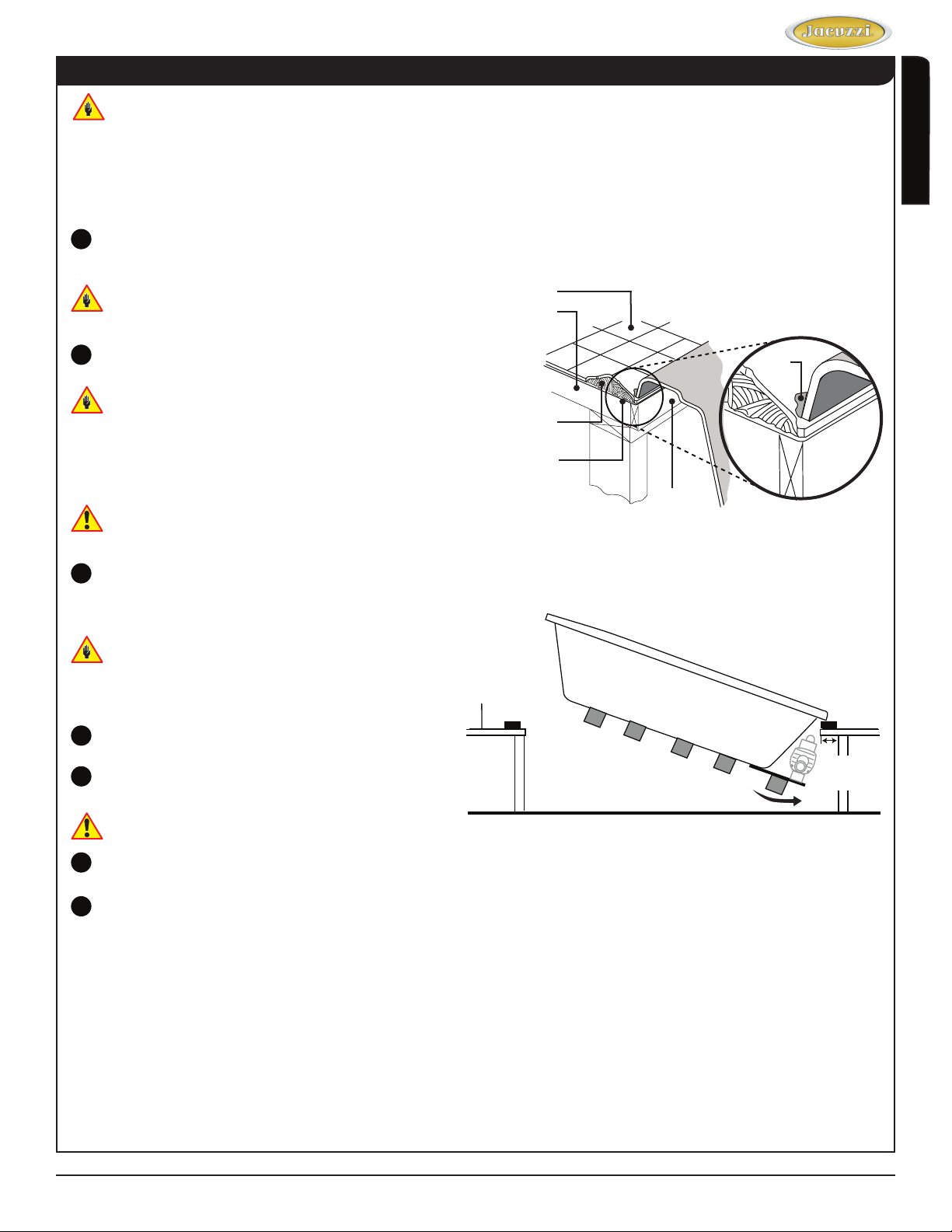
The unit must be supported from the bottom of the
•
bathtub and not from the bathtub rim. For drop-in
installations, take into account the thickness of the
surround material and nishing material (marble, tile,
etc.).
Ensure the rim will rest on a level surface.
•
Per code, access must be provided to the motor/pump
•
for your specic model. Primary and secondary service
access locations are shown in the rough-in diagrams
contained in the Technical Specications Manual.
Figure 1 shows common access locations.
It is the responsibility of the installer, building
contractor, or owner to provide access for service.
Jacuzzi is not responsible for any costs relating to
obtaining access for repair. The owner shall bear such
costs and, if appropriate, must seek recovery from the
installer.
Provide adequate ventilation for cooling and supply
•
sufcient air for the motor/pump. Do not insulate
around the equipment.
Your bathtub may have motor/pump parts that extend
•
beyond the rim of the bathtub. Refer to the rough-in
diagrams included in the warranty pack and
construction framing to correctly accommodate.
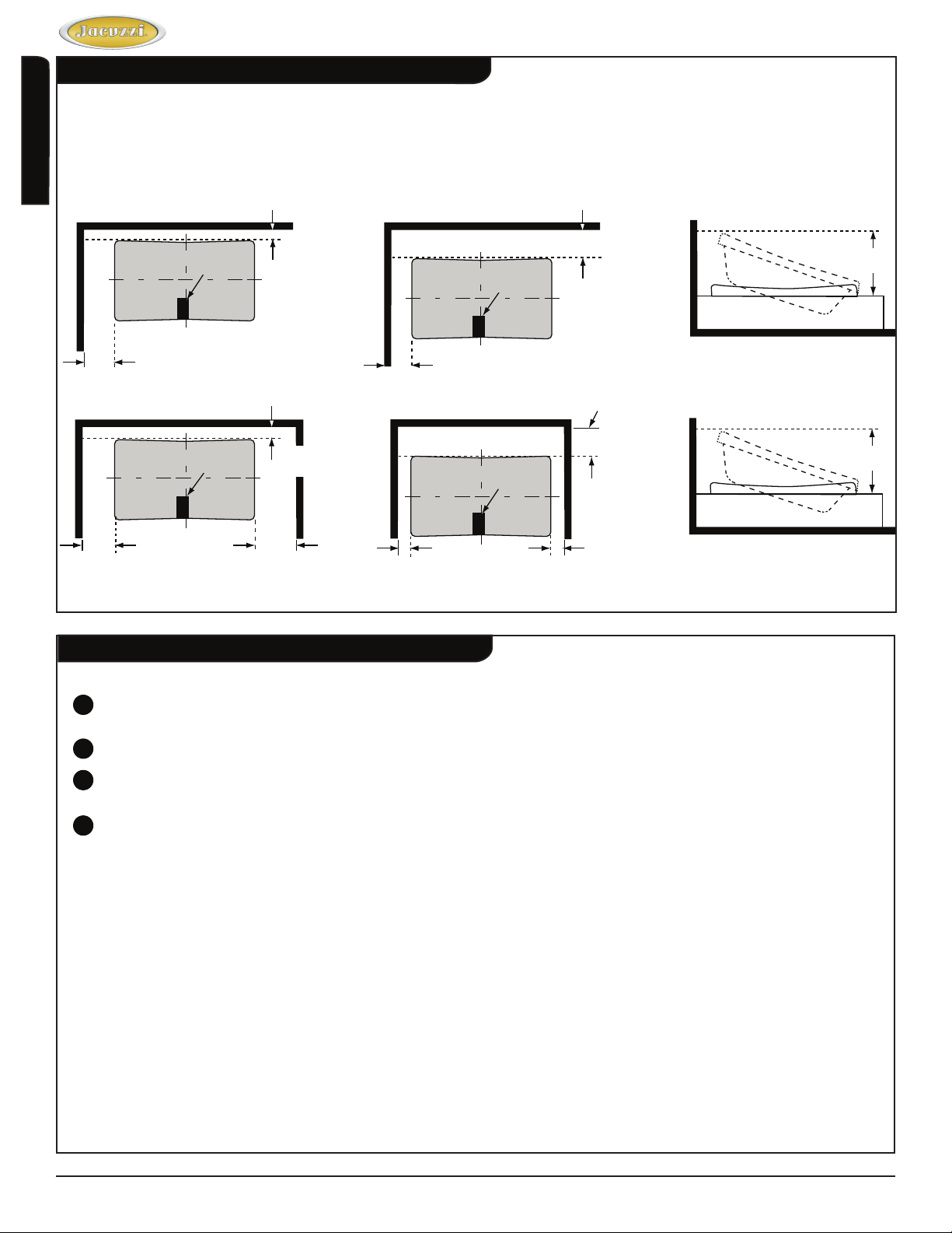
Common Access Locations
12˝
(304mm)
18˝
(457mm)
Figure 1
18˝
(457mm)
B
36˝
(914mm)
= Primary access
A
= Acceptable alternative if access A is not possible
B
= Secondary access for equipment (optional)
C
Left hand unit access is on the opposite side (mirror).
Secondary
Alternate
Access
Access
A
24˝
(609mm)
Blower
C
Primary
Access
12˝
(304mm)
18˝
(457mm)
20˝
(508mm)
Blower
English
Figure 2
Installation and Operation www.jacuzzi.com Page 7
Page 8
Framing (con’t)
To ensure the installer has space to maneuver and install the bathtub, allow adequate wall and ceiling
•
clearance (Figure 3).
Luxury Whirlpool Bath
English
2-Wall Installation
BATHTUB
CUTOUT
32˝
(812mm)
3-Wall Installation
BATHTUB
CUTOUT
32˝
(812mm)
Floor Cutout for
Drain/Overow
Floor Cutout for
Drain/Overow
3˝
(76mm)
3˝
(76mm)
32˝
(812mm)
Clearance Examples
BATHTUB
CUTOUT
10˝
(254mm)
BATHTUB
CUTOUT
10˝
(254mm)
Floor Cutout for
Drain/Overow
Floor Cutout for
Drain/Overow
Figure 3
32˝
(812mm)
32˝
(812mm)
10˝
(254mm)
48˝
(1219mm)
48˝
(1219mm)
Suboor
Prepare the suboor for the drain and ensure that the area is level.
The drain/overow of the bathtub extends below the bottom of the bathtub. Identify the drawing in the Technical
1
Specications Manual that corresponds with your bathtub.
Make appropriate cuts to the suboor to accommodate the drain.
2
Jacuzzi’s Tru-Level™ base is a standard feature on all bathtubs. If the suboor is level and a continuous surface,
3
no other preparation is necessary. Proceed to the “Installation” section.
If the suboor is not level, you must level the entire surface prior to installing the bathtub. The materials used
4
will insure that the bathtub is supported from the bottom. These materials include: leveling compound, mortar,
plaster or minimal expansion structural foam (having a density of a minimum 5lbs/cubic foot). The bathtub must
remain level in order for it to drain properly and must make contact with the leveling material. Both sides of a joint
or splice of suboor should be level to each other.
Page 8 www.jacuzzi.com Installation and Operation
Page 9

Luxury Whirlpool Bath
Fuzion™ Specic Material
The additional design features of the Fuzion™ require that the following steps be completed prior to installing the
bathtub in the constructed surround. The following steps must also be completed in the order specied:
Fuzion™ Overow/Drain Installation
•
Fuzion™ Wood Frame Installation
•
Fuzion™ Control Panel Installation
•
Fuzion™ Faucet Installation
Selecting a faucet for rim mounting: The combined thickness at the rim of the bathtub shell and optional
wood deck is 2˝ (50mm) nominal. The length of the faucet tailpiece(s) must be long enough to extend past
this dimension and have ample clearance to assemble any hardware (i.e. locknut, water supply fittings, etc.)
necessary for installation. For undermount units, the combined thickness of the bathtub shell is ½˝ (12mm)
nominal and the undermount deck should not exceed the length of the faucet tailpiece(s), including any
assembly hardware.
Fuzion™ Overow Drain Installation
Overow Fitting
English
Assemble in accordance with the local plumbing or
building codes.
Identify drain overow kit provided with your
1
bathtub. Remove and open the overow package
and conrm that all parts are present.
Remove washers and nuts from the overow tting.
2
Place a small bead of plumbers putty, silicone, or
3
similar approved sealant around the underside of
the top ange of the overow tting.
Place the overow tting into the overow hole of
4
the bathtub (Figure 3).
From the underside of the unit, place the rubber
5
washer then locknut on the overow tting and
tighten securely. Be careful not to overtighten.
Assemble the remaining drain pieces as shown in
6
the illustration.
After the drain is fully installed, test for proper
7
drainage. If the unit does not drain properly, rectify
this condition before proceeding with further
bathtub installation.
Watertight installation of the drain and overow
is the installer’s responsibility. Drain leakage is
excluded from the Jacuzzi Luxury Bath warranty of
this product
Flat Rubber
Washer
Lock Nut
Direct Waste
Overow Drain
PVC Flex Pipe
Figure 3 - Overow Installation
Overow Drain
Assembly
PVC 45
Elbow Street
PVC 45 Elbow
Apply sealant/caulking
(commercially available)
Direct Waste Overow Drain
PVC Flex Pipe
PVC 45 Elbow
PVC Flex Pipe
PVC 45 Elbow Street
Twist and Turn
Drain Assembly
PVC Pipe
PVC Pipe
OPTIONAL - If the Fuzion™ Wood Frame is not being used,
please proceed to Step 2 in the Undermount Installation section.
Waste Elbow
Installation and Operation www.jacuzzi.com Page 9
Page 10
Fuzion™ Frame Installation
If you are installing a Fuzion™ bathtub with accessory
frame, please refer to the Fuzion™ Frame Installation
Guide (#GL44000) before proceeding any further.
Complete the installation and assembly steps
according to the Fuzion™ Frame Installation Guide.
English
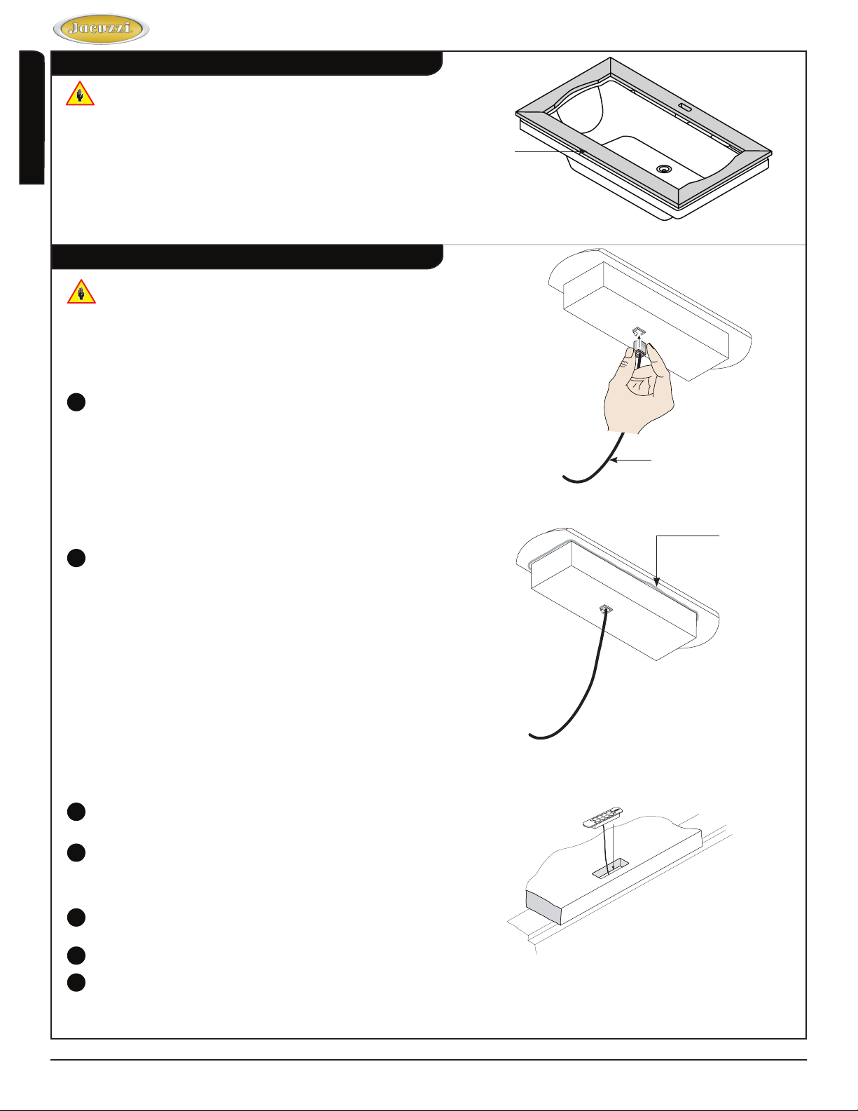
Fuzion™ Control Panel Installation
The following cutouts must be clear and free of any dirt
or adhesive:
- Control panel cutout in the assembled wood frame
- Control panel cutout in the assembled counter
- Control panel cutout in the bathtub
Insert the wire connector into the back of the control
1
panel (Figure 4).
Luxury Whirlpool Bath
Fuzion™ Frame
Sparingly apply adhesive around the base of the
2
control panel (Figure 5).
Thread the wire through the cutout and to the control
3
box.
Orient control panel in the following manner: the logo
4
will be on the right side of the J4 control panel when
you are sitting in the bathtub (the power button will be
on the right side of the J5 LCD control panel).
Control Box Wire
(Black Wire)
Figure 4 - Control Panel
Figure 5 - Adhesive Application
Control Box Wire
Adhesive)
Lower the control panel into the cutout and press rmly
5
to embed the adhesive (Figure 6).
Connect the wire to the control box.
6
Please proceed to Step 3 in the Drop-In Installation
7
section.
Figure 6 - Control Panel
Inside of Bathtub
Page 10 www.jacuzzi.com Installation and Operation
Page 11

Luxury Whirlpool Bath
Electrical Connections
Risk of electric shock. Connect only to a circuit
protected by a GFCI.
When using electrical products, basic precautions
should always be followed:
Always follow local building and electrical codes.
•
Grounding is required. The unit should be
•
installed and grounded by a qualied electrician.
Two separate GFCI protected circuits are required.
A separate, 120VAC, 20 Amp GFCI circuit is required for
the pump/motor.
A separate, 120VAC, 15 Amp GFCI circuit is required for
the heater.
Risk of component overheat. Do not use electric extension cord to power this unit.
Operating the motor/pump without enough water in the bathtub can cause leaking and permanent damage.
English
Reset
Test
At initial startup, the 7 button electronic control system enters an automatic self diagnostic program for 15-20
seconds. During the diagnostic program, the system will not accept user commands.
Pump/Motor and Heater
For the pump/motor, install a 120 VAC, 20AMP,
1
GFCI duplex outlet to the stud wall underneath the
Power Cord from Control
Box to GFCI Circuit
bathtub at 4˝ (101mm) above the oor. The duplex
outlet is not supplied.
The duplex outlet must be mounted 4˝ (101mm)
above the oor line, or in accordance with local
building and electrical codes.
Using a #8 solid copper wire, ground the pump
2
motor to the house electrical panel, or approved
local ground. A grounding lug is provided on the
pump motor
For the heater, install a 120VAC, 15 AMP RATED
3
GFCI single outlet to the wall stud underneath the
bathtub, at least 4˝ (101mm) above the oor. The
M
T
Power Cord from Heater
Box to GFCI Circuit
single outlet is not provided.
With a #8 solid copper wire, ground the heater to
4
Heater
the house electrical panel or approved local bond. A
grounding lug is provided on the heater.
4˝
(101mm)
At initial start-up, and before each use thereafter with power ON, push the GFCI test button. The reset button
5
should pop out.
Push this button in to reset. If the interrupter fails to operate in this manner, there is a ground current owing or a
device malfunction, indicating the possibility of electrical shock.
Turn OFF power and do not use the bathtub until the source of the problem has been identied and corrected.
Installation and Operation www.jacuzzi.com Page 11
Page 12
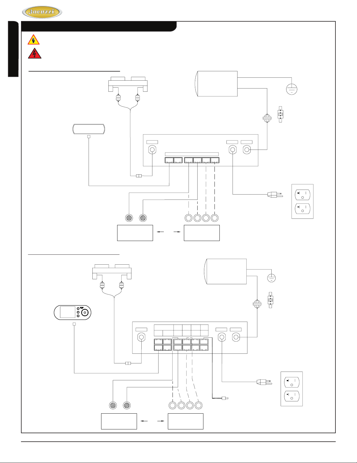
Reference Illustrations
These illustrations are for reference only, as the unit comes fully assembled.
Risk of electric shock. Before servicing these connections, disconnect all power supply cables to both 120VAC
services.
English
J4 Control Panel Schematic Diagram
Luxury Whirlpool Bath
CONTROL
PANEL
AIR VALVE ASSEMBLY
CHROMETHERAPY
LIGHTS
Air Valve
Panel
OR
CONTROL BOX
Blower
PUMP/MOTOR
LED Light
ILLUMATHERAPY
LIGHTS
120VAC
SEE VIEW A
Pump
LEAD CONNECTIONS
4
4-WHITE-C
3
3-BLACK-H
2
2-RED-L
1
1-GREEN-GRD
VIEW A
120VAC 20A
GFCI
J5 Control Panel Schematic Diagram
AIR VALVE ASSEMBLY
CONTROL PANEL
CHROMETHERAPY
LIGHTS
Air Valve
OR
RS232
Panel
CONTROL BOX
Inside
Light 1
Inside
Blower
Light 2
ILLUMATHERAPY
Inside
Light 3
Inside
Light 4
LIGHTS
Ambient
Light 1
Ambient
Light 2
Temp
Sensor
LOGO
Light
PUMP/MOTOR
Pump
120 VAC
TEMPERATURE
SEE VIEW A
SENSOR
LEAD CONNECTIONS
4
4-WHITE-C
3
3-BLACK-H
2
2-RED-L
1
1-GREEN-GRD
VIEW A
120VAC 20A
GFCI
Page 12 www.jacuzzi.com Installation and Operation
Page 13
Luxury Whirlpool Bath
Drop-in Installation
Before you begin your installation, please read the following:
Observe all local and building codes.
•
Determine which tools will be used during the installation.
•
Additional bathtub drain parts and plumbing are commercially available at plumbing and hardware stores.
•
Drain/Overow rough-in information is included with your bathtub in the installation instruction manual.
•
Complete the bathtub surround installation (Figure 8).
Install drain/overow according to the
1
manufacturer’s instructions. Refer also to the
Technical Specications Manual.
Watertight installation of the drain is the installer’s
responsibility. Drain leakage is excluded from the
Jacuzzi Luxury Bath warranty of this product.
Install the faucet at this time. It is recommended
2
that the faucet be installed by a qualied plumber.
Proper installation of the spout plumbing and
compliance with local codes are the responsibility of
the installer. Jacuzzi Luxury Bath does not warrant
connections of water supply ttings and piping,
ll systems, or drain/overow systems. Nor is it
responsible for damage to the bathtub which may
occur during installation.
A non-ammable protective barrier must be placed
between the soldering work and the bathtub unit to
prevent damage to the bathtub.
Prepare the cut-out hole for the bathtub using
3
either the provided full scale template or the cutout
dimensions listed in the specications table in the
Technical Specications Manual.
Tile
Suboor
Mortar or
Adhesive
Flashing
1˝ x 4˝
(25mm x 101mm)
Not For Support
Figure 8
English
Sealant
Exploded View
The template may show guides for more than one
bathtub, be certain to select the appropriate guide
lines. If under mounting is an option, be careful to
select the guide lines that apply to the installation
that you are performing.
Complete all deck nish work and cover to protect
4
from damaging while placing the bathtub.
Insulation may be placed within the bathtub
5
surround.
Provide adequate ventilation around the motor/
pump to ensure sufcient airow and cooling.
Turn off power supply to dedicated GFCI protected
6
circuits.
Place a piece of scrap lumber on each of the ends
7
of the cutout – this will be used as a temporary
support prior to lowering the bathtub fully into the
opening (Figure 9).
Tile or Finished
Surface
Scrap Lumber
Substrate
Support
Member
Level Suboor
Figure 9
Scrap Lumber
Minimum 3˝
(76mm)
Clearance
Installation and Operation www.jacuzzi.com Page 13
Page 14
Drop-in Installation (con’t)
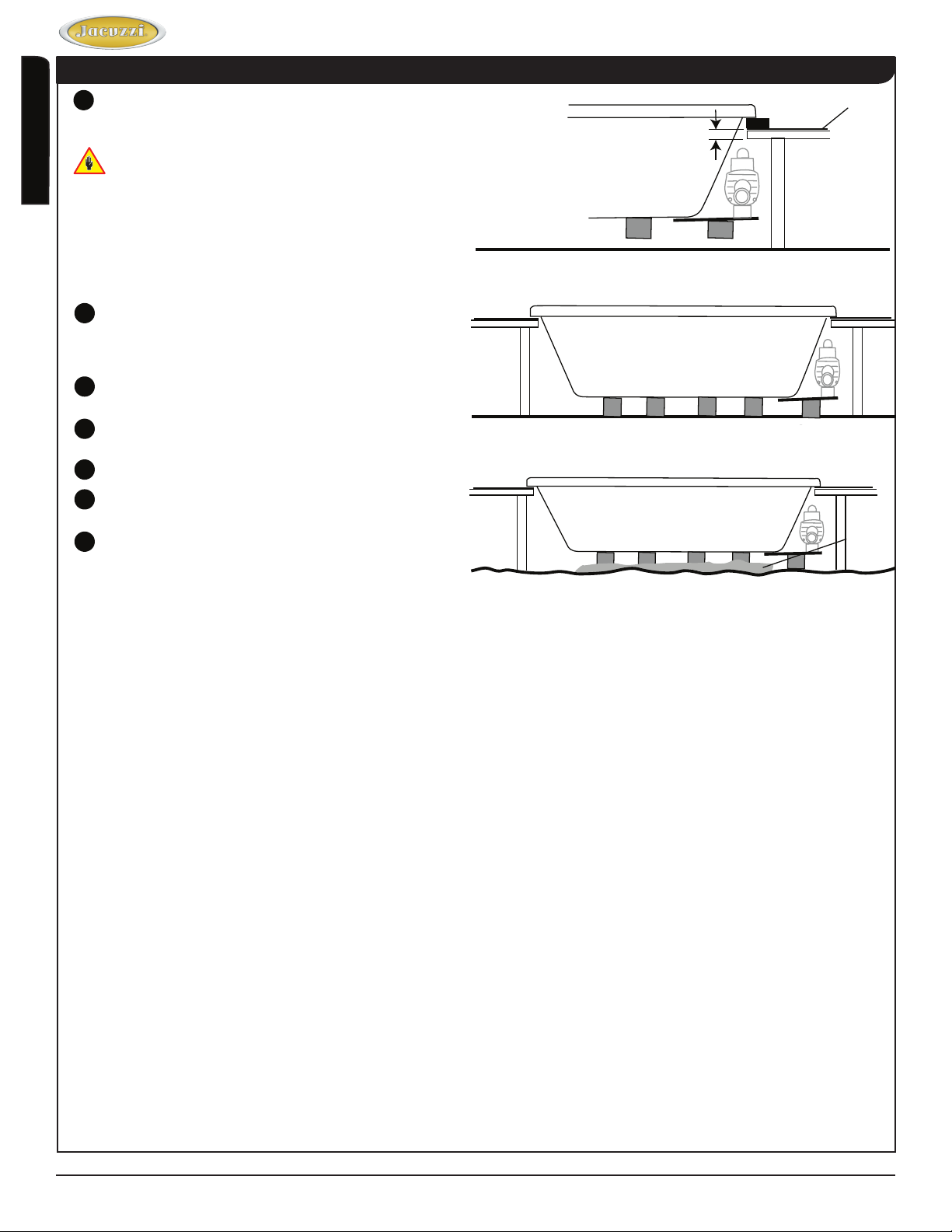
Install the unit, inserting the motor/pump end rst,
8
lowering the bathtub into the opening as shown in
the illustration (Figure 10).
DO NOT use plumbing xtures or lines to lower the
English
unit. Allow the bathtub to rest on the supports.
Maximum 2˝
(50mm)
Thickness
Luxury Whirlpool Bath
Tile or
Scrap Lumber
Substrate
Finished
Surface
Inspect all ttings, plumbing, and control lines
9
after inserting to insure the components are not
damaged, disconnected, or contacting the nish
surface substrate or support members.
Connect ex water supply lines to faucet and plug
10
power cords into GFCI outlets.
Remove scrap lumber and lower the bathtub fully
11
into the opening (Figures 11 and 12).
Align the bathtub and connect the drain.
12
Turn on the power supply to the dedicated GFCI
13
protected circuits and check system operation.
Caulk around the perimeter of bathtub to seal the
14
space between the rim and the nished deck.
Level Suboor
Uneven
Suboor
Level Suboor
Figure 10
Figure 11
Figure 12
Member Support
Floating
Floor
Compound
Page 14 www.jacuzzi.com Installation and Operation
Page 15

Luxury Whirlpool Bath
Undermount Installation
Install drain/overow according to the manufacturer’s
1
instructions.
Watertight installation of the drain is the installer’s
responsibility. Drain leakage is excluded from the Jacuzzi
Luxury Bath warranty of this product.
Turn off power supply to dedicated GFCI protected
2
circuits.
Template
Bathtub Rim
English
Install the unit in desired location. DO NOT use plumbing
3
xtures or lines to carry or lower the unit.
Inspect all ttings, plumbing, and control lines after
4
inserting to insure the components are not damaged or
disconnected.
Align the bathtub and connect the drain.
5
Insulation may be placed within the bathtub surround.
6
Provide adequate ventilation around the motor/pump to
ensure sufcient air ow and cooling.
Cut deck/counter to t using the undermount template
7
provided as follows:
Position the template so that the desired undermount
•
guidelines are aligned with the rim edge as shown
(Figure 12).
Using a grease pencil, mark the center lines (denoted
•
by on template). Remove template.
Measure the distance from the wall, or other xed point,
•
to the center lines (Figure 13).
Afx counter to bathtub. Clean any dirt or debris from the
8
top of the bathtub rim. Apply a bead of silicone sealant
around the entire rim of bathtub.
Do not use an adhesive or adhesive sealant to secure the
counter to the bathtub. If maintenance or remodeling is
required, the counter may have to be removed. Adhesive
will permanently bond the counter to the bathtub. Carefully
position the deck/counter over the bathtub. Follow
manufacturer’s instructions to determine cure time.
Figure 12 - Template Placement
A
B
D
TemplateCounter
Figure 13 - Distance Measurement
C
Apply a continuous bead of silicone sealant around
9
the entire seam between the counter and the bathtub
rim. Allow sealant to cure according to manufacturer’s
instructions.
Turn on the power supply to the dedicated GFCI protected
10
circuits and check system operation.
Cleanup
To avoid dulling and scratching the surface of the bathtub, never use abrasive cleaners. For most soiled surfaces, a
mild liquid detergent and warm water is sufcient. The following is also recommended:
Remove spilled plaster with a wood or plastic edge. Spots left by plaster or grout can be removed if lightly rubbed
•
with detergent on a damp cloth or sponge. Do not use metal scrapers, wire brushes or other metal tools, as they
will damage the bathtub’s surface.
Paint, tar, or other difcult stains can be removed with Fantastik® or soapy water.
•
Minor scratches which do not penetrate the color nish can be removed by lightly sanding with 600-grit wet/dry
•
sandpaper. You can restore the glossy nish to the acrylic surface of the bathtub with a special compound,
Meguiar’s #10 Mirror Glaze. If that is not available, use automotive rubbing compound followed by an application
of automotive paste wax.
Major scratches and gouges which penetrate the acrylic surface will require renishing. Call Jacuzzi Luxury Bath
•
to nd a service agent in your area.
Installation and Operation www.jacuzzi.com Page 15
Page 16

General Operation Information
All bathtubs manufactured by Jacuzzi Luxury Bath are
designed for “ll and drain,” which means the bathtub
should be drained after each use and lled with fresh
water by the next bather. This is a health precaution,
as these bathtubs are not designed to hold water
English
continuously like pools or spas.
Luxury Whirlpool Bath
Two control panel types are available for the Luxury
Whirlpool series. Refer to details below:
J4 Luxury Electronic Control Panel:
•
Operational instructions for this panel is listed
below.
Optional J5 Luxury LCD Control Panel:
•
Operation instructions for this panel are outlined in
the supplemental guide provided in your warranty
pack. Refer to this document for complete operation
details (P/N GU47000).
Close the drain and ll the bathtub until water is at
least 1˝ to 2˝ (25mm to 51mm) above the highest jet
(see water line indicated in the illustration). Do not turn
on the whirlpool system at any time if the jets are not
completely immersed in water. Running the whirlpool
system when there is insufcient water in the bathtub
could result in water spraying outside the bath area.
Running the whirlpool system without water will damage
the recirculating pump.
When exiting the bathtub, the water level will drop
below the jets which could result in water being
sprayed out of the unit. To prevent this, you must
turn unit OFF before exiting bathtub.
Main Menu
J4 Control Panel
J5 Control Panel
POWER
Fill to at least 1˝ to 2˝
above highest jet
Whirlpool Operation
ON: Press the jet button once to turn the whirlpool jets
ON.
The whirlpool motor will be on high speed. The indicator
lights at left will illuminate brightly.
OFF: Press the jet button a second time to turn the
whirlpool jets OFF.
If in chromatherapy lighting mode (indicator lights
to the left of the jet button are dim), you will need to
press jet button once to resume whirlpool operation
mode and then a second time to turn the whirlpool
power off.
Page 16 www.jacuzzi.com Installation and Operation
Jet
Page 17

Luxury Whirlpool Bath
Decrease Speed
Press the (-) button to decrease whirlpool speed.
There are 2 whirlpool motor speeds, high and low. The
indicator lights display the setting.
1 light on = Low speed
•
4 lights on = High speed
•
Increase Speed
Press the (+) button to increase whirlpool speed.
There are 2 whirlpool motor speeds, high and low. The
indicator lights display the setting.
1 light on = Low speed
•
4 lights on = High speed
•
Air Flow
Press the left air valve button to active the left air valves,
press the right air valve button to activate the right air
valves.
The amount of air induced into the whirlpool jets can be
controlled from maximum to none. Use the (+) and (-)
buttons to increase or decrease air ow.
HighLow
English
HighLow
Left Right
The indicator lights immediately to the left and right of the air
valve buttons indicate the amount of air induced.
Wave Mode
Press the wave button to cycle the air ow in the jets
from maximum to no air ow.
If the wave mode does not initiate, ensure that you are
in whirlpool operation mode (lights immediately to the
left of the jet button should be brightly lit).
Both right and left air valves are cycled simultaneously
from a closed position (no air) to open (max air).
The indicator lights will display the ow as it cycles from
minimum to maximum. To turn off wave mode, press the
(wave) button.
Installation and Operation www.jacuzzi.com Page 17
Page 18

Luxury Whirlpool Bath
Chromatherapy or Allumitherapy (Light) Operation
Press light button 1st time:
Turns colored lighting ON, use up and down buttons to start
color scroll or select alternate color.
Press light button 2nd time:
English
Turns white lighting ON, use up and down buttons to select
intensity of white light.
Press light button 3rd time:
Turns all lighting OFF
Colored Lighting Operation
The colored lighting default is constant blue. Pressing the (+) button activates color scroll in this order: blue, teal,
green, yellow, orange, red, pink, purple and then returns to blue and continuously repeats. To stop on a selected color,
press the (+) button again. Pressing the (-) button activates color scroll in this order: blue, purple, pink, red, orange,
yellow, green, teal and then returns to blue and continuously repeats. To stop on a selected color, press the (-) button
again.
White Lighting Operation
There are ve white light intensities. Press the (+) button to increase light intensity. Press the (-) button to decrease
light intensity.
Controlling Whirlpool Direction and Flow
Direction -
All Jacuzzi jets, except the rotating neck jets, can be driectionally
adjusted. To change the direction of the water ow, swivel the jet
nozzle to the desired angle. The jets can be directed individually
toward any location on your body to provide a hydromassage.
The jets can also be adjusted so that they all point in the same
direction (clockwise or counterclockwise) to circulate the water in
a circular motion around the bath, causing a total whirlpool effect.
Water Force -
Most Jacuzzi jets are designed for ow adjustment. For robust
action, increase the force of the ow by rotating the nozzle, or
face, to the left (counterclockwise). For a more gentle effect, or to
close off the jet, rotate the nozzle, or face, to the right (clockwise).
Closing one or more jets can increase the water force in the
remaining jets.
The rotating neck jets, and some AccuPro™ jets, cannot be
adjusted for water force.
Never run the whirlpool system with all the jets closed.
Multidirectional Jets
Page 18 www.jacuzzi.com Installation and Operation
Page 19

Luxury Whirlpool Bath
RapidHeat™
The heater turns ON automatically any time whirlpool operation is active. Heater operation is not displayed on the
control panel. There is a visible indicator light on the heater itself that signies the heater is operating. The heater will
help maintain the temperature of the water in the bathtub.
Vacuum Switch
The heater is equipped with a preset vacuum switch which will not allow the heater to turn ON if the pump is not
running and water is not owing through the whirlpool system.
High-Limit Switch
The heater includes an exclusive High-Limit switch. This
safety circuit will not false trip from hot tap water. It will
only turn OFF the heater if the thermostat fails. To reset,
press the button. If the high-limit trips frequently, please
contact us at www.jacuzzi.com, or at 1-800-288-4002.
OVER HEAT
PROTECTION
PUSH TO RESET
High Limit
Reset
HEATER ON
Heater
On
Purging the Whirlpool System
To remove accumulations of bathtub residue from the whirlpool system, it is recommended that a whirlpool bathtub be
cleaned at least twice a month. For best results, however, we recommend that you clean your whirlpool bathtub after
each use using, Systems Clean™, our exclusive two-part plumbing system cleaner made specically for whirlpool
bathtubs. Systems Clean™ is available through an authorized Jacuzzi Whirlpool Bath Distributor or by calling us direct
at 1-800-288-4002.
English
Bathtub Additives
Do not use oil or oil-based bathtub additives.
If you want to use any kind of bathtub additive, use only a small amount of low-foaming powder or crystal substance;
the whirlpool action intensies the foaming properties of soaps.
The use of certain bathtub oils, bubble baths, and bathtub additives may increase the level of accumulations of bathtub
residue in the whirlpool system and may cause false reading of the water level sensors. If excess accumulations
persist, you should discontinue use of these products.
Installation and Operation www.jacuzzi.com Page 19
Page 20

Luxury Whirlpool Bath
Maintenance
To clean your bathtub, simply use a mild, nonabrasive liquid detergent solution. You can protect and restore the gloss
to a dulled acrylic surface by applying Meguiar’s #10 Mirror Glaze, a product specically designed for use on acrylic
nishes. If Meguiar’s is not available, use a ne grade automotive rubbing compound followed by an application of
automotive paste wax.
English
Never use abrasive household cleaners on any Jacuzzi Luxury Bath product.
Surface Repair
Minor scratches which do not penetrate the color nish can be removed by lightly sanding with 600-grit wet/dry
sandpaper. Restore the gloss using Meguiar’s Mirror Glaze or automotive paste wax. Major scratches and gouges
which penetrate the acrylic surface will require renishing. Call Jacuzzi Luxury Bath to nd a service agent in your area.
Spinning Jet Maintenance
If hair, or other types of debris, get caught in the bearings
of these jets, it could cause them to stop spinning. This
may require disassembly and removal.
To do this, simply grab the nozzle and pull it straight out
of the jet housing. The bearing casing will be attached to
the nozzle. These two items can be separated by holding
the casing and pushing the nozzle out from the rear of
the casing. After the cleaning is complete, reassemble
and reinstall.
Suction Cover/Strainer Maintenance
Clean the suction cover/strainer of hair and debris when
necessary.
Remove the center screw and detach the suction
1
cover.
Clean the cover by backushing debris from the holes.
2
Replace the suction cover immediately after cleaning.
3
When reinstalling, orient the cover/strainer with the
small notch at the bottom. The gasket must be inserted
into the groove of the cover/strainer before reinstalling
onto the suction tting.
Keep hair a minimum of 6 inches (152 mm) away
from the suction tting at all times when the
whirlpool system is operating. Hair longer than
shoulder length should be secured close to the
head, or a bathing cap should be worn.
Do not operate the whirlpool system with the
suction cover/strainer removed!
It is a safety device and must always be in place on
the suction tting to minimize the potential hazard
of hair and body entrapment.
Suction FittingSuction Cover
Screw Notch Gasket
Page 20 www.jacuzzi.com Installation and Operation
Page 21

Luxury Whirlpool Bath
Troubleshooting Procedures
PROBLEM PROBABLE CAUSES REMEDY
Pump/motor does not start
Pump/motor operates but no fully adjustable jets are
functioning
No power to pump/motor
Pump/motor not plugged in
Pump/motor faulty
Jets are closed
Reset GFCI
Insert plug securely into outlet
Ensure the control panel is conencted to control box
Contact Jacuzzi Luxury Bath @ 800-288-4002
Open jets by rotating counter-clockwise
English
Pump/motor operates but air is not injected into the
water
Water leakage from pump unions
Pump/motor shuts off by itself before time elapses
Chromatherapy lights do not operate
Suction cover/strainer may be clogged
Air valves are closed
Overtightened, O-ring may be pinched or improperly
seated, undertightened
Motor thermal protection has deactivated pump/motor
due to overheating (supply voltage low)
GFCI tripped
Inadequate supply wiring
Connector has come loose
With the motor turned OFF, remove the suction cover/
strainer and remove any debris. Replace the suction
cover before operating
Open air control valves
Loosen unions , check and reseat O-ring. If O-ring has
been pinched out of shape, replace (refer to number
below). When tightening union nuts, handtighten only.
Let motor cool; thermal protection will reset. Check for
proper ventilation (check supply voltage)
Reset GFCI. If it continues to trip, do not use this unit.
Disconnect the unit and have the problem corrected by
a licensed electrician before using.
Consult a licensed electrician to correct the wiring unit.
Contact Jacuzzi Luxury Bath @ 800-288-4002
If the unit is within the warranty period, contact Jacuzzi Whirlpool Bath Service Support at 1-800-288-4002 with your bath’s serial number
before work is started. The serial number is located on the Specication/Serial Number Plate (see the following page).
Installation and Operation www.jacuzzi.com Page 21
Page 22

Luxury Whirlpool Bath
Authorized Service
If you need a referral for a service company near you, or need assistance with operation or maintenance-related
questions, please call our Service Support Department at 1-800-288-4002. Visit our web site at http://www.jacuzzi.com/
for products, services, and an online copy of these Installation and Operation Instructions.
When requesting service or technical assistance please have available both the model and serial number of your
English
unit. This information can be obtained from the product registration card provided with your unit. If the card has been
misplaced, this information can be obtained from the specication/serial number label on the unit itself. The label is
located on the wall of the bathtub near the pump/motor.
SPECIFICATION/SERIAL NUMBER LABEL
Core Number,
Serial Number
You will nd your serial
number here
XXXX-XXXXX
MODEL: XXXXXXX
NAME: XXXXX
COLOR: XXXXX
MFG#: XXXXX
SER#: XXXXXX
Appropriate Safety Compliance Logos for your unit.
Applicable Electrical Specications for your unit.
Electrical specications printed in this area.
Made in the USA
PRODUCT SPECIFICATIONS ARE SUBJECT TO CHANGE WITHOUT NOTICE.
USE TECHNICAL SPECIFICATIONS MANUAL SUPPLIED WITH PRODUCT.
Jacuzzi® Luxury Bath has obtained applicable code (standards) listings generally available on a national basis for products of this
type. It is the responsibility of the installer/owner to determine specic local code compliance prior to installation of the product.
Jacuzzi® Luxury Bath makes no representation or warranty regarding, and will not be responsible for any code compliance.
Jacuzzi® Luxury Bath
14525 Monte Vista Avenue
Chino, California, 91710
1-800-288-4002
www.jacuzzi.com
Page 22 www.jacuzzi.com Installation and Operation
Page 23

Limited Lifetime Warranty on Jacuzzi Luxury Branded Baths for the Comfort, Comfort Plus,
Warranty
Luxury Whirlpool Bath
Pure Air®, Luxury, Salon™ Spa, and Pure Air® II Collections
WARRANTY COVERAGE
Jacuzzi Luxury Bath (the “Company”) offers the following expressed limited lifetime warranty to the original purchaser of any Jacuzzi® Luxury Bath products provided
in the Company’s Comfort, Comfort Plus, Pure Air®, Pure Air® II, and Luxury™ collections ("Bath") who purchases the Bath for personal or single family residential use
(“User”): The Company will repair or replace, at its sole option, the Bath or its equipment in accordance with the following terms and conditions. This warranty does not
apply to non-branded Bath products manufactured by the Company.
LIFETIME WARRANTY ON BATHS
The Company extends to the User of the Bath a non-transferable limited lifetime warranty that the shell will maintain its structural integrity and conguration and be free
of water loss due to a defect in the bathtub shell. This warranty covers only the bathtub shell and the manufacturer installed pump, jets, controls, and blower against
defects in material or workmanship. This warranty does not apply to any display models or to any options or accessories which are covered under our limited ninety (90)
day warranty set forth below. Warranty coverage begins on the date the unit was originally purchased by the User and upon receipt by the Company of a completely
lled out Warranty Registration Card as described below.
2 YEAR LABOR WARRANTY FOR ALL FACTORY INSTALLED COMPONENTS
Our limited labor warranty is for a period of two (2) years from the date the unit was originally purchased by the User, but not more than Three (3) Years from date of
manufacture. All factory installed components (e.g., pump, motor, blower, and plumbing) are covered under our labor warranty against failure due to defects in materials
and workmanship.
NINETY DAY (PARTS ONLY) LIMITED WARRANTY ON OPTIONS AND ACCESSORIES
Our limited warranty on options and accessories is for ninety (90) days for parts only. Our warranty covers options and accessories manufactured (e.g., drains ll
spout kits, trim kits, skirts, video monitors, plasma television screens, CD and MP3 players and other music and video devices and optional heaters) against defects
in material or workmanship. Warranty coverage begins on the date the option or accessory was originally purchased by the User. These items may be covered by a
manufacturer's warranty which may have a longer duration than this limited warranty. Please conrm with the manufacturer the duration of the appropriate warranty for
Options and Accessories.
WARRANTY LIMITATIONS
Our limited warranty does not cover defects, damage, or failure caused by the common carrier, installer, user, or other persons, pets, or rodents, or resulting from,
without limitation, any of the following: careless handling (lifting unit by plumbing, abrading nish, etc.) including its own negligence; modication of any type for any
reason (including modication to meet local codes); improper installation (including installation not in accordance with instructions and specications provided with
the unit); connections supplied by the installer of the equipment; improper voltage supply or unauthorized electrical modication; misuse; incorrect operation, or lack
of proper routine maintenance; operation of the unit without specied minimum amount of water or at inappropriate water temperature; use of abrasive or improper
cleaners; or acts of God, such as lightning, oods, earthquakes, etc.
In addition, THE COMPANY WILL NOT BE RESPONSIBLE FOR INCIDENTAL OR CONSEQUENTIAL DAMAGES or losses arising from any cause (e.g., water
damage to carpet, ceiling, tiles, marble, loss of use, etc.) including its own negligence; damages to, respecting, or resulting from: plated parts when pool and/or spa
chemicals are used in the unit or hard water conditions; optional bath equipment not manufactured by the Company but supplied by Dealer, installer or the Company;
the unit's prior usage as an operational display; or defects that should have been discovered before installation.
This limited warranty does not include: labor, transportation, or other costs incurred in the removal and/or reinstallation of the original unit and/or installation of a
replacement unit; any costs relating to obtaining access for repair; or loss of use damage, including loss of sales, prot or business advantage of any kind under any
circumstances. Bath units are excluded from any warranty coverage if any addition, deletion, or modication of any kind whatsoever has been made to the unit (or to
any component). Warranty coverage is provided in the United States of America and Canada only.
EXCLUSION OF IMPLIED WARRANTIES
IMPLIED WARRANTIES OF MERCHANTABILITY AND FITNESS FOR A PARTICULAR PURPOSE ARE DISCLAIMED ALTOGETHER OR TO THE FULLEST EXTENT
ALLOWED BY LAW.
NOTICE: This warranty gives you specic legal rights, and you may also have other rights which vary from state to state. There are no warranties applicable to Jacuzzi
Luxury Bath products except as expressly stated herein or as implied by applicable state and federal laws. The Company will not be responsible for any statements or
representations made in any form that go beyond, are broader than or are inconsistent with any authorized literature or specications furnished by the Company. Some
states do not allow limitations on how long an implied warranty lasts, or the exclusion or limitation of incidental or consequential damages, so the above limitations and
exclusions may not apply to you.
Luxury Bath by Jacuzzi
HD84000
English
®
Jacuzzi® Luxury Bath
14525 Monte Vista Avenue
Chino, California 91710
Installation and Operation www.jacuzzi.com Page 23
Page 24

RETURN OF WARRANTY REGISTRATION
To register your product, please go to our website Jacuzzi.com, click on Bath and Showers, then select ONLINE WARRANTY REGISTRATION from the top of the page.
You will then be prompted to enter your product Serial Number followed by your warranty registration information. Or you may also register by completing the registration
below and mailing it to jacuzzi at the address provided below.
The attached Warranty Registration MUST be lled out by the purchaser within thirty (30) days from purchase and received by Jacuzzi Luxury Bath in order for this
warranty to become effective.
RESPONSIBILITIES OF OTHERS
Inspecting the unit prior to installation is the responsibility of the installer or building contractor who acts on behalf of the User. They are responsible for ensuring the unit
is free of defect or damage. Notices are placed on and in the unit and on the shipping carton advising the installer of this responsibility. In the event of a problem, the unit
English
must not be installed. The Company is not responsible for failures or damage that could have been discovered, repaired, or avoided by proper inspection and testing
(including proper water testing) prior to installation.
Damage occurring in transit is the responsibility of the carrier. The User or installer MUST open the crate and inspect the unit for damage when it is delivered. If damage is
discovered, it must be reported immediately to the seller and the carrier in writing, and an inspection requested. Failure of the carrier to respond should be reported to the
seller and the carrier. Your freight claims should be led promptly thereafter.
Damage occurring to the unit during installation is the responsibility of the installer and/or building contractor and damage occurring thereafter is the responsibility of the
user.
Failure of any optional equipment is the sole responsibility of the equipment manufacturer except as provided above and shall not extend to or apply to any replacement
parts for the Options and Accessories. Any replacement parts shall be covered by the original equipment manufacturer.
The Distributor or Dealer is responsible for knowing local code requirements and notifying the installing contractor and/or User of these requirements at the time of
purchase. The Company is not responsible for costs to modify any product to obtain any code approval, such as city, county, or state building codes in U.S.A. or municipal
or provincial codes in Canada.
For the customer's benet, the Company maintains a list of independent service personnel to perform required warranty service repairs. Such rms are not agents or
representatives of the Company and cannot bind the Company by words or conduct.
The Company will provide the warranty service described above when the following conditions have been met: the failure is of the nature or type covered by the warranty;
the User has informed an Authorized Jacuzzi Luxury Bath Service Agent or Warranty Service Department Representative of the nature of the problem during the warranty
period; conclusive evidence (e.g., proof of purchase or installation) is provided to the foregoing by the user proving that the failure occurred or was discovered within the
warranty period; an authorized independent service person or Company representative has been permitted to inspect the unit during regular business hours within a
reasonable time after the problem was reported by the User. In order to obtain warranty service, contact Jacuzzi Luxury Bath at:
To obtain warranty replacement for factory-installed components for Company supplied options and accessories manufactured and supplied by the Company, call or write
the above. Provide a description of the problem and proof of purchase. You will be instructed how to obtain replacements and where to return, at your expense, the failed
component(s), option(s), or accessory(ies).
All replacement parts, equipment, and repairs shall assume the remaining warranty period of the part(s) replaced.
The Company's warranty obligation shall be discharged upon tender of replacement or repair. The customer's refusal to accept the tender terminates the Company's
warranty obligation.
Limited Warranty
Accessory(ies)
Ninety-Day
Parts Only
WARRANTY SERVICE
jacuzzi.com
or
Warranty Service Department
14525 Monte Vista Avenue
Chino, California 91710
Call: 1-(800) 288-4002
Luxury Whirlpool Bath
On
Limited Warranty
Accessory(ies)
Ninety-Day
Parts Only
( ) Other _______________________________________________
6. What is the current market value of this property?
Please estimate $________________________________________
7. What is the age of the head of the household? _____________ years
8. What other manufacturers did you consider?
( ) Eljer ( ) Lasco ( ) Price Pster ( ) Aqua Glass
( ) Kohler ( ) American Standard ( ) Sterling
( ) Other (Specify) _______________________________________
9. How long did you shop before purchasing unit?
( ) 1 day ( ) 2 months- 6 months
( ) 2-7 days ( ) 6 months- 1 year
( ) 1 week- 2 weeks ( ) 1 year- 2 years
( ) 2 weeks- 4 weeks ( ) +2 years
( ) 1 month- 2 months
10. Approximately how long have you lived in this home?____________
11. Please indicate, approximately, the total annual income of your house-
( ) Up to $24,999 ( ) $50,000 to $74,999
( ) $25,000 to $29,999 ( ) $75,000 to $99,999
( ) $30,000 to $39,999 ( ) $100,000 to $149,999
( ) $40,000 to $49,999 ( ) $150,000 and Above
12. Was your purchase process?
( ) Very easy ( ) Easy ( ) Difcult ( ) Very Difcult
13. How technically aware were you of the patented Jacuzzi® jet system
( ) Not aware ( ) Somewhat aware ( ) Very aware
prior to your purchase?
hold.
( ) Dealer/Plumbing Supplier ( ) Builder ( ) Remodeler
( ) Plumbing Contractor ( ) Retailer/Home Center Store
( ) Decorator/Architect ( ) Already Installed
3. What was the main reason for purchase?
( ) Styling ( ) Warranty Service ( ) Product Features
( ) Brand Name ( ) Price ( ) Hydrotherapy
( ) Home Resale _________________________________________
( ) Other _______________________________________________
4. Who nally decided which product you would buy?
( ) Self ( ) Spouse ( ) Self and Spouse Together
( ) Other Family Member ( ) Designer/Architect
( ) Builder/Plumber/Remodeler ( ) Already Installed
5. Who installed? ( ) Already installed/New Home
( ) Contractor/Plumber when remodeling
( ) Self/Spouse when remodeling
Model Name ______________________________________________
Serial Number _____________________________________________
Dealer's Name _____________________________________________
Dealer's Address ___________________________________________
1. How did you rst hear about this Jacuzzi® product?
( ) Advertisement ( ) Article in Magazine/Newspaper
( ) Visited Dealer/Plumbing Supplier ( ) Yellow Pages
( ) Builder/Plumber/Remodeler ( ) Decorator/Architect
( ) Visited Retailer/Home Center Store
( ) Word of Mouth . . . Friend/Relative/Acquaintance
( ) Other (Please Describe) _________________________________
2. Who rst gave you specic information about this product (specications,
prices, etc.)?
Date of Purchase ___________________________________________
Purchaser's Name __________________________________________
Purchaser's Address ________________________________________
City _____________________________ State ______Zip _________
(30) days from date of purchase in order for this warranty to be come effective.
On
JACUZZI LUXURY BATH
HD84000
Page 24 www.jacuzzi.com Installation and Operation
To complete your product registration, visit our website at www.jacuzzi.com, or
ll out and mail this card to the address printed on the other side within thirty
WARRANTY
REGISTRATION CARD
Page 25

Luxury Whirlpool Bath
English
SERIE DE BAÑERAS
LUXURY WHIRLPOOL®
INSTRUCCIONES PARA LA INSTALACIÓN Y EL FUNCIONAMIENTO
Jacuzzi® Luxury Bath
14525 Monte Vista Avenue
Chino, CA 91710
1-800-288-4002
www.jacuzzi.com
HD84000
Installation and Operation www.jacuzzi.com Page 25
Page 26

EnglishEspañol
Luxury Whirlpool Bath
Page 26 www.jacuzzi.com Installation and Operation
Page 27

Luxury Whirlpool Bath
Bañera de hidromasaje de lujo
Contenido
Contenido....................................................................................................................................................27
Información del producto.............................................................................................................................27
Instrucciones de seguridad..........................................................................................................................28
Instrucciones de seguridad operacional......................................................................................................29
Inspección y prueba....................................................................................................................................30
Estructura....................................................................................................................................................31
Material especíco Fuzion™.......................................................................................................................33
Conexiones eléctricas.................................................................................................................................35
Instalación empotrada.................................................................................................................................37
Instalación de montaje bajo cubierta...........................................................................................................39
Limpieza......................................................................................................................................................39
Información general sobre el funcionamiento..............................................................................................40
Funcionamiento Whirlpool...........................................................................................................................42
Control de la dirección y del ujo Whirlpool.................................................................................................42
Purga del sistema Whirlpool........................................................................................................................43
Aditivos para baño.......................................................................................................................................43
Mantenimiento.............................................................................................................................................44
Procedimientos para la resolución de problemas....................................................................................... 45
Servicio técnico autorizado..........................................................................................................................46
Español
English
Garantía.......................................................................................................................................................47
Información del producto
Conserve estas instrucciones para uso futuro. Utilice el formulario a continuación para registrar su
modelo y número de serie para referencia futura.
Fecha de la
compra
Comprado a
Instalado por
Número de serie
Modelo
Instalador: Deje el manual para el propietario.
Propietario: Lea este manual y consérvelo para referencia futura.
Instalación y Operación
Installation and Operation www.jacuzzi.com Page 27
Page 28

Bañera de hidromasaje de lujo
Luxury Whirlpool Bath
Instrucciones de seguridad
INSTRUCCIONES RELATIVAS A RIESGOS DE INCENDIO, DESCARGAS ELÉCTRICAS O LESIONES A PERSONAS.
Éste es un producto de calidad profesional. Se requieren conocimientos de técnicas de construcción, fontanería e
instalación eléctrica conforme a los códigos para la instalación apropiada y la satisfacción del usuario. Recomendamos
que un contratista matriculado realice la instalación de todos los productos Jacuzzi® Luxury Bath. Nuestra garantía no
cubre problemas relacionados con instalaciones inadecuadas.
EnglishEspañol
PRECAUCIÓN: AL UTILIZAR ESTA UNIDAD, SIEMPRE DEBE TOMAR LAS PRECAUCIONES BÁSICAS, QUE
INCLUYEN LO SIGUIENTE:
LEA Y SIGA TODAS LAS INSTRUCCIONES. CONSERVE ESTAS
•
INSTRUCCIONES.
Utilice esta unidad sólo para el n para el cual fue diseñada, según se describe en este
•
manual. No utilice accesorios que no están recomendados por el fabricante.
Nunca deje caer ni introduzca objetos en ninguna de las aberturas.
•
ADVERTENCIA: RIESGO DE LESIONES ACCIDENTALES O AHOGAMIENTO.
No permita que los niños utilicen esta unidad a menos que sean supervisados atentamente en todo
momento. No utilice la bañera de hidromasaje a menos que todas las tapas protectoras de succión estén
instaladas para evitar que el cabello o partes del cuerpo queden atrapados. Nunca utilice la bañera de
hidromasaje si la tapa protectora de succión está rota, dañada o extraviada.
PELIGRO: RIESGO DE LESIONES GRAVES POR DESCARGA ELÉCTRICA O MUERTE POR
ELECTROCUCIÓN
Esta unidad se debe conectar solamente a un circuito de suministro que esté protegido por un interruptor
de circuito con detección de falla a tierra (GFCI, por su sigla en inglés) de 15 A. Dicho GFCI debe ser
uministrado por el instalador y debe ser puesto a prueba habitualmente. Para probar el GFCI, pulse el
botón de prueba. El GFCI debería interrumpir la alimentación. Pulse el botón de restablecimiento. La
alimentación debería restablecerse. Si el GFCI no funciona de esta manera, el GFCI está defectuoso. Si
el GFCI interrumpe la alimentación hacia la bañera sin que se pulse el botón de prueba, un ujo de
corriente de retorno por tierra está indicando la posibilidad de una descarga eléctrica. No utilice esta
bañera de hidromasaje. Desconecte la bañera de hidromasaje y haga corregir el problema por un
representante calicado del servicio técnico antes de usarla.
ADVERTENCIA: RIESGO DE DESCARGA ELÉCTRICA
Realice la conexión solamente a un circuito protegido por un interruptor de circuito con detección de falla
a tierra (GFCI). (Para unidades conectadas permanentemente) Hay un terminal de color verde (o un
conector de cable) marcado como “G”, “GR”, “GROUND” o “GROUNDING” dentro del compartimiento
del terminal. Para reducir el riesgo de descarga eléctrica, conecte el terminal o el conector al terminal a
tierra de su servicio eléctrico o panel de alimentación con un conductor de igual tamaño a los conductores
del circuito que alimentan el equipo.
PRECAUCIÓN: Este equipo está previsto para uso en interiores solamente. Instale el equipo conforme a estas instrucciones.
Utilice los cables de alimentación adecuados para 167 °F (75 °C), incluido el índice de temperatura de los
conductores de alimentación que se van a utilizar. Esta unidad debe conectarse eléctricamente a tierra,
y debe instalarla un contratista, electricista o fontanero matriculado. Los materiales de construcción y
el cableado deben direccionarse lejos del motor/bomba o del generador de burbujas de aire, o de otros
componentes de producción de calor de esta unidad. En el exterior del motor/bomba y del calentador, se
proporciona un conector de cable de presión para facilitar la conexión de un conductor de unión de cobre
sólido N.º 8 AWG entre esta unidad y todos los otros equipos eléctricos y los metales expuestos próximos,
según sea necesario para cumplir con los requerimientos locales.
Instrucciones importantes de seguridad de la Asociación de Normas
Canadienses (sólo para modelos canadienses)
Cuando utilice este equipo eléctrico, siempre debe tomar las precauciones de seguridad básicas, que incluyen las siguientes:
1. ADVERTENCIA: RIESGO DE LESIONES ACCIDENTALES O AHOGAMIENTO. LOS NIÑOS NO DEBEN UTILIZAR
BAÑERAS DE HIDROMASAJE SIN LA SUPERVISIÓN DE UN ADULTO. BAÑERA DE HIDROMASAJE CON
CALENTADOR.
2. ADVERTENCIA: RIESGO DE LESIONES ACCIDENTALES O AHOGAMIENTO. NO UTILICE LA BAÑERA DE
HIDROMASAJE A MENOS QUE TODAS LAS TAPAS PROTECTORAS DE SUCCIÓN ESTÉN INSTALADAS PARA
EVITAR QUE EL CABELLO O PARTES DEL CUERPO QUEDEN
ATRAPADOS.
3 ADVERTENCIA: PARA EVITAR LESIONES, TENGA CUIDADO AL ENTRAR O SALIR DE LA BAÑERA DE
HIDROMASAJE.
4. ADVERTENCIA: RIESGO DE LESIONES ACCIDENTALES O AHOGAMIENTO. NO UTILICE DROGAS O ALCOHOL
ANTES O DURANTE LA UTILIZACIÓN DE UNA BAÑERA DE HIDROMASAJE CON CALENTADOR PARA EVITAR
LA PÉRDIDA DEL CONOCIMIENTO Y UN POSIBLE AHOGAMIENTO.
5. ADVERTENCIA: RIESGO DE LESIÓN FETAL. LAS MUJERES EMBARAZADAS O CON POSIBILIDAD DE
EMBARAZO DEBEN CONSULTAR A UN MÉDICO ANTES DE UTILIZAR UNA BAÑERA DE HIDROMASAJE CON
CALENTADOR.
6. ADVERTENCIA: RIESGO DE HIPERTEMIA Y POSIBLE AHOGAMIENTO: NO UTILICE UNA BAÑERA DE
HIDROMASAJE CON CALENTADOR INMEDIATAMENTE DESPUÉS DE REALIZAR EJERCICIOS FÍSICOS
EXTENUANTES.
7. CONSERVE ESTAS INSTRUCCIONES.
Page 28 www.jacuzzi.com Installation and Operation
Instalación y Operación
Page 29

Luxury Whirlpool Bath
Bañera de hidromasaje de lujo
Instrucciones de seguridad operacional
ADVERTENCIA: RIESGO DE HIPERTERMIA Y POSIBLE AHOGAMIENTO!
No utilice una bañera de hidromasaje con calentador inmediatamente después de
realizar ejercicios físicos extenuantes.
ADVERTENCIA: RIESGO DE DESCARGA ELÉCTRICA
•
o televisores dentro de un radio de 60 pulgadas (1524 mm) de esta bañera de
hidromasaje.
•
tenga un nivel de agua de, al menos, 1 a 2 pulgadas (de 25 a 51 mm) por encima
del oricio de aire más alto.
•
•
supercie.
•
más de 140 ºF (60 ºC).
ADVERTENCIA: LA INMERSIÓN PROLONGADA EN AGUA CALIENTE PUEDE CAUSAR
HIPERTERMIA
La hipertermia ocurre cuando la temperatura interna del cuerpo alcanza un nivel superior
a la temperatura corporal normal de 98,6 ºF (37 ºC). Los síntomas de la hipertermia
incluyen el aumento de la temperatura corporal interna, mareos, aletargamiento,
somnolencia y desvanecimiento. Los efectos de la hipertermia incluyen los siguientes:
A. Incapacidad para percibir el calor.
B. Incapacidad para reconocer la necesidad de salir de la bañera.
C. Desconocimiento de un peligro inminente.
D. Daño fetal en mujeres embarazadas.
E. Incapacidad física para salir de la bañera.
F. PÉRDIDA DEL CONOCIMIENTO CON PELIGRO DE AHOGAMIENTO.
No utilice electrodomésticos como secadores de pelo, lámparas, teléfonos, radios
No ponga en funcionamiento el sistema de hidromasaje a menos que la bañera
No sumerja el panel de control llenando en exceso la bañera.
No utilice sustancias abrasivas para limpiar su bañera, ya que pueden dañar la
Para evitar la decoloración del acabado acrílico, no llene la bañera con agua a
Español
Español
English
ADVERTENCIA: RIESGO DE LESIÓN FETAL
LAS MUJERES EMBARAZADAS O CON POSIBILIDAD DE EMBARAZO DEBEN
CONSULTAR A UN MÉDICO ANTES DE UTILIZAR UNA BAÑERA DE HIDROMASAJE
CON CALENTADOR.
ADVERTENCIA: El uso de alcohol, drogas o medicamentos puede aumentar en gran medida el riesgo
de hipertermia fatal. Las personas que tomen medicamentos o tengan una historia clínica
desfavorable deben consultar a un médico antes de utilizar una bañera de hidromasaje
con calentador.
ADVERTENCIA: NO ALTERE LOS CONTROLES OPERADOS POR EL USUARIO NI LOS DISPOSITIVOS
SEMEJANTES.
ADVERTENCIA: UTILICE ESTA UNIDAD SÓLO PARA EL FIN PARA EL CUAL FUE DISEÑADA, SEGÚN
SE DESCRIBE EN ESTE MANUAL. NO UTILICE ACCESORIOS QUE NO ESTÁN
RECOMENDADOS POR LOS FABRICANTES.
ADVERTENCIA: PARA EVITAR LESIONES, TENGA CUIDADO AL ENTRAR Y AL SALIR DE LA BAÑERA
DE HIDROMASAJE.
ADVERTENCIA: No utilice la bañera de hidromasaje a menos que todas las tapas protectoras de succión
estén instaladas para evitar que el cabello o partes del cuerpo queden atrapados. Nunca
utilice la bañera de hidromasaje si la tapa protectora de succión está rota, dañada o
extraviada.
ADVERTENCIA: La temperatura del agua que excede los 104 ºF (40 ºC) puede resultar perjudicial para su
salud. Controle y regule la temperatura del agua antes de utilizar la bañera.
PRECAUCIÓN: Controle el interruptor de circuito con detección de falla a tierra que protege este
dispositivo de forma periódica conforme a las instrucciones del fabricante.
IMPORTANT: LEA LAS INSTRUCCIONES COMPLETAS PROPORCIONADAS EN ESTE MANUAL
ANTES DE COMENZAR LA INSTALACIÓN.
La empresa ha obtenido los listados de los códigos (normas) aplicables que suelen estar disponibles a nivel nacional
para productos de este tipo. Es responsabilidad del instalador o propietario determinar el cumplimiento de los códigos
locales especícos antes de instalar el producto. La empresa no realiza manifestaciones ni ofrece garantías con
respecto al cumplimiento de ningún código, ni será responsable de dicho cumplimiento. Las especicaciones del
producto están sujetas a cambio sin previo aviso.
Instalación y Operación
Installation and Operation www.jacuzzi.com Page 29
Page 30

Bañera de hidromasaje de lujo
Luxury Whirlpool Bath
Inspección y prueba
Inspección visual
Retire la bañera de la caja de envío. Tenga cuidado de no rayar la supercie de la bañera con las grapas
1
expuestas. Retire las grampas o pliéguelas hacia el interior de la caja. Conserve la caja hasta que la inspección
del producto haya sido satisfactoria. Nunca levante la bañera sujetándola por la fontanería; solo hágalo por el
EnglishEspañol
armazón.
Inspeccione el armazón y los componentes de la bañera. En caso de que la inspección revele cualquier daño
2
o defecto en el acabado o daño visible en los componentes, no instale la bañera. Los daños o defectos en el
acabado reclamados después de la instalación de la bañera están excluidos de la garantía. La responsabilidad
de Jacuzzi Luxury Bath por daños durante el transporte naliza contra entrega de los productos en buen estado
al transportista.
Presente sus reclamos por daños al transportista. Para conocer los términos de la cobertura y las limitaciones
3
de la garantía, consulte la información publicada sobre la garantía embalada con el producto o al dorso de este
manual.
Vericación del funcionamiento y del agua de
la bañera
El funcionamiento apropiado de todas las unidades y el buen estado de las conexiones herméticas son probados
en fábrica antes del envío. No obstante, el instalador debe examinar la unidad nuevamente antes de la instalación.
Jacuzzi Luxury Bath no se hace responsable de ningún defecto que pudiera haberse descubierto, reparado o evitado
de haberse seguido este procedimiento de inspección y prueba:
Coloque la bañera sobre una supercie nivelada, cerca de un suministro eléctrico, suministro de agua y drenaje
1
de agua adecuados. Una vía de acceso es una opción adecuada.
Selle el oricio de drenaje y de desborde con una cinta o un tapón y llene la bañera hasta la base del oricio de
2
desborde.
Permita que el agua de la bañera repose por 5 minutos.
3
Conecte el motor/la bomba y encienda la unidad. Conrme que todas las características funcionen según se
4
describe en la sección de Funcionamiento de este manual. No instale la bañera si no funciona como se describe.
Inspeccione visualmente todas las uniones para ver si existen pérdidas. No instale la bañera si se detectan
5
pérdidas.
Vuelva a colocar la bañera en la caja o de lo contrario protéjala de daños hasta el momento de la instalación.
6
Page 30 www.jacuzzi.com Installation and Operation
Instalación y Operación
Page 31

Luxury Whirlpool Bath
Bañera de hidromasaje de lujo
Estructura
Se ha incluido un Manual de especicaciones técnicas con su bañera. El Manual de especicaciones técnicas incluirá
la información importante relacionada a su producto Jacuzzi Luxury Bath. Haga uso del Manual de especicaciones
técnicas en este momento.
Las dimensiones proporcionadas en los diagramas
•
de instalación son nominales. Tome las medidas
de su unidad al recibirla y construya conforme a las
dimensiones reales.
La estructura del piso debajo de la bañera debe poder
•
soportar el peso total de la bañera, el agua y el
ocupante.
La bañera debe estar apoyada sobre su base, no
•
sobre su borde. En el caso de instalaciones
empotradas, tenga en cuenta el espesor del material
de recubrimiento y del material de acabado (mármol,
azulejo, etc.).
Asegúrese de que el borde descanse en una
•
supercie nivelada.
Por norma, se debe facilitar el acceso al motor/
•
la bomba de su modelo especíco. Las ubicaciones
principales y secundarias de acceso al servicio se
muestran en los diagramas de instalación incluidos
en el Manual de especicaciones técnicas. La Figura
1 muestra las ubicaciones comunes de acceso.
Ubicaciones comunes de acceso
12˝
(304mm)
18˝
(457mm)
Acceso
Alternate
secundario
Access
Figura 1
Generador de burbujas
de aire
Acceso
principal
12˝
(304mm)
18˝
(457mm)
EnglishEspañol
Es responsabilidad del instalador, el contratista
de obra o el propietario proporcionar el acceso al
servicio. Jacuzzi no se responsabiliza de ninguno
de los costos relacionados con la obtención de
accesos para efectuar reparaciones. El propietario
debe soportar dichos costos y, si es apropiado, debe
solicitar el reintegro del instalador.
Provea una ventilación apropiada para el enfriamiento
•
y un suministro de aire suciente para el motor/la
bomba. No coloque aislamiento alrededor del equipo.
La bañera puede tener piezas del motor/la bomba que
•
se prolongan más allá del borde de la bañera.
Consulte los diagramas de instalación incluidos
en el paquete de la garantía y la estructura para la
construcción para ubicarla de forma correcta.
18˝
(457mm)
B
36˝
(914mm)
= Acceso principal
A
= Alternativa aceptable en caso de que el acceso A no
B
sea posible
= Acceso secundario para el equipo (opcional)
C
El acceso a la unidad por la izquierda se encuentra en el
lado opuesto (en espejo).
Figura 2
A
24˝
(609mm)
20˝
(508mm)
C
Generador
de burbujas
de aire
Instalación y Operación
Installation and Operation www.jacuzzi.com Page 31
Page 32

Estructura (continuación)
Para asegurarse de que el instalador tenga espacio suciente para maniobrar e instalar la bañera, deje un
•
espacio libre respecto a la pared y el cielorraso (Figura 3).
Instalación entre dos paredes
EnglishEspañol
RECORTE DE
BAÑERA
32˝
(812mm)
Instalación entre tres paredes
RECORTE DE
BAÑERA
3˝
(76mm)
Recorte del piso para
drenaje/desborde
3˝
(76mm)
Ejemplos de espacio libre
RECORTE DE
BAÑERA
Recorte del piso para
drenaje/desborde
10˝
(254mm)
RECORTE DE
BAÑERA
32˝
(812mm)
32˝
(812mm)
Bañera de hidromasaje de lujo
Luxury Whirlpool Bath
48˝
(1219mm)
48˝
(1219mm)
32˝
(812mm)
Recorte del piso para
drenaje/desborde
32˝
(812mm)
10˝
(254mm)
Recorte del piso para
drenaje/desborde
10˝
(254mm)
Figura 3
Contrapiso
Prepare el contrapiso para el drenaje y asegúrese de que el área esté nivelada.
El drenaje/desborde de la bañera se extiende por debajo de la parte inferior de ésta. Identique la ilustración que
1
corresponde a su bañera en el Manual de especicaciones técnicas.
Realice los cortes adecuados en el contrapiso para ubicar el drenaje.
2
La base Tru-Level™ de Jacuzzi es una característica estándar en todas las bañeras. Si el contrapiso
3
está nivelado y tiene una supercie continua, no es necesario realizar otra preparación. Vaya a la sección
“Instalación”.
Si el contrapiso no está nivelado, debe nivelar toda la supercie antes de instalar la bañera. Los materiales
4
utilizados asegurarán que la bañera esté sostenida desde la parte inferior. Estos materiales incluyen:
compuesto de nivelación, mortero, yeso o espuma estructural de mínima expansión (con una densidad de un
mínimo de 5 lb/pie cúbico). La bañera debe permanecer nivelada para que pueda drenar adecuadamente,
y debe hacer contacto con el material de nivelación. Ambos lados de la unión o el empalme del contrapiso
deben estar nivelados.
Page 32 www.jacuzzi.com Installation and Operation
Instalación y Operación
Page 33

Luxury Whirlpool Bath
Bañera de hidromasaje de lujo
Material especíco de Fuzion™
Las características de diseño adicionales de Fuzion™ requieren que se completen los siguientes pasos antes de
instalar la bañera en el recubrimiento construido. Los pasos siguientes además deben completarse en el orden
especicado:
Instalación del desagüe/desborde Fuzion™
•
Instalación del marco de madera Fuzion™
•
Instalación del panel de control Fuzion™
•
Instalación del grifo Fuzion™
Selección de un grifo para el montaje en el borde de la bañera: El espesor combinado del borde del armazón
de la bañera y la plataforma opcional de madera es de 2” (50 mm) nominales. La longitud del/de los apéndice/s
del grifo debe ser lo sucientemente extensa para superar esta dimensión y tener espacio suciente para
ensamblar cualquier herraje (es decir, contratuerca, accesorios para el suministro de agua, etc.) necesario para
la instalación. Para las unidades de montaje bajo cubierta, el espesor combinado de la carcasa de la bañera es
de un valor nominal de ½” (12 mm), y la plataforma de montaje bajo cubierta no debe superar la longitud del/de
los apéndice/s, incluidos los herrajes para montaje.
Español
English
Instalación del drenaje/desborde Fuzion™
Montaje conforme a los códigos de fontanería y de
construcción locales.
Identique el equipo de drenaje de desbordes
1
proporcionado con su bañera. Retire y abra
el conjunto de desbordes y conrme que se
encuentren todas las partes.
Extraiga las arandelas y las tuercas del accesorio
2
de desborde.
Coloque una pequeña cantidad de masilla de
3
fontanería, silicona o un sellador similar autorizado
alrededor de la base del ala superior del accesorio
de desborde.
Coloque el accesorio de desborde en el oricio de
4
desborde de la bañera (Figura 4).
Desde la parte inferior de la unidad, coloque la
5
arandela de goma, luego ajuste la contratuerca
en el accesorio de desborde y apriete para que
quede asegurado. Tenga cuidado de no apretar
demasiado.
Arme las piezas restantes de drenaje como se
6
muestra en la ilustración.
Luego de que el drenaje esté completamente
7
instalado, pruébelo para controlar que el
drenaje sea apropiado. Si la unidad no drena
adecuadamente, corrija esta condición antes de
continuar con la instalación de la bañera.
La instalación hermética del drenaje y el sistema
contra desbordes es responsabilidad del instalador.
La pérdida del drenaje no está incluida en la
garantía Jacuzzi Luxury Bath de este producto.
Arandela plana
Drenaje de desbordes
de descarga directa
Codo macho-hembra
de 45, PVC
de goma
Contratuerca
Tubo exible,
PVC
Tubo exible,
PVC
Codo de 45,
PVC
Armado del drenaje
contra desbordes
Codo machohembra de 45, PVC
Codo de 45, PVC
Tubo exible,
PVC
Accesorio de desborde
Aplique sellador o masilla
(comercialmente disponible)
Drenaje de desbordes de
descarga directa
Armado del drenaje
circular y en espiral
Tubo de
OPCIONAL – Si el marco de madera Fuzion™ no se utiliza,
continúe con el Paso 2 en la sección de Instalación de montaje
bajo cubierta.
Instalación y Operación
Installation and Operation www.jacuzzi.com Page 33
PVC
Tubo de
PVC
Codo de
descarga
Figura 4. Instalación del sistema contra desbordes
Page 34

Instalación del marco Fuzion™
Si está instalando una bañera Fuzion™ con un marco
accesorio, consulte la Guía de instalación del marco
Fuzion™ (#GL44000) antes de continuar. Complete
los pasos de armado e instalación conforme a la Guía
de instalación del marco Fuzion™.
EnglishEspañol
Instalación del panel de control Fuzion™
Los siguientes recortes deben estar limpios y libres de
suciedad o adhesivos. :
- Recorte del panel de control en el marco de madera
armado
- Recorte del panel de control en la encimera armada
- Recorte del panel de control en la bañera
Inserte el conector de cable en la parte posterior del
1
panel de control (Figura 5).
Marco Fuzion™
Bañera de hidromasaje de lujo
Luxury Whirlpool Bath
Cable de la caja
de control (cable
negro)
Aplique una pequeña cantidad de adhesivo alrededor
2
de la base del panel de control (Figura 6).
Pase el cable por el recorte y hacia la caja de control.
3
el panel de control de la siguiente manera: el logotipo
4
estará en el lado derecho del panel de control J4
cuando usted esté sentado en la bañera (el botón de
encendido estará a la derecha del panel de control de
LCD J5).
Figura 5. Panel de control
Figura 6. Aplicación del adhesivo
Cable de la
caja de control
(adhesivo)
Baje el panel de control hacia el recorte y presione
5
con rmeza para incrustar el adhesivo (Figura 7).
Conecte el cable con la caja de control.
6
Vaya al Paso 3 en la sección de Instalación
7
empotrada.
Figura 7. Panel de control
Page 34 www.jacuzzi.com Installation and Operation
Dentro de la
bañera
Instalación y Operación
Page 35

Luxury Whirlpool Bath
Bañera de hidromasaje de lujo
Conexiones eléctricas
Riesgo de descarga eléctrica. Realice la conexión
solo a un circuito protegido por un GFCI.
Al utilizar productos eléctricos, siempre debe tomar
las siguientes precauciones básicas:
Siempre siga los códigos para el sistema
•
eléctrico y de construcción locales.
Es necesario una conexión a tierra. La unidad
•
debe ser instalada y conectada a tierra por un
electricista calicado.
Se necesitan dos circuitos independientes protegidos por
un GFCI.
Se requiere un circuito independiente protegido con un
GFCI de 120 VAC, 15 A, para el motor/la bomba.
Se requiere un circuito independiente protegido con un
GFCI de 120 VAC, 15 A, para el calentador.
Riesgo de calentamiento excesivo de los componentes. No utilice el prolongador eléctrico para suministrar
corriente a esta unidad.
El funcionamiento del motor/la bomba sin la cantidad de agua suciente en la bañera puede provocar pérdidas y
daño permanente.
EnglishEspañol
Restablecer
Prueba
En la puesta en marcha inicial, el sistema de control electrónico de 7 botones introduce un programa de
autodiagnóstico automático durante 15 a 20 segundos. Durante el programa de diagnóstico, el sistema no
aceptará comandos del usuario.
Motor/la bomba y calentador
Para el motor/la bomba, instale una toma doble con
1
GFCI de 120 VAC, 20 A en la pared de entramado
Cable de alimentación de la caja
de control al circuito de GFCI
por debajo de la bañera 4” (101 mm) sobre el piso.
No se incluye la toma doble.
La toma doble debe instalarse 4” (101 mm) por
encima de la línea del piso o de acuerdo con los
códigos eléctricos y de construcción locales.
Utilice un alambre de cobre sólido N.º 8 para
2
conectar a tierra el motor de la bomba a la caja de
distribución eléctrica de la casa o a una conexión
local aprobada. Se proporciona un terminal de toma
4˝
(101mm)
a tierra en el motor de la bomba.
Para el calentador, instale una toma simple con
3
GFCI con capacidad NOMINAL de 15 VAC, 20 A
M
T
Cable de alimentación del
calentador al circuito de GFCI
en la pared de entramado por debajo de la bañera
4” (101 mm) sobre el piso. No se incluye la toma
simple.
Con un alambre de cobre sólido N.º 8, conecte a
4
Calentador
tierra el calentador a la caja de distribución eléctrica
de la casa o unión local aprobada. Se proporciona
un terminal de puesta a tierra en el calentador.
En la puesta en marcha inicial, y antes de cada uso posterior con la alimentación activada, oprima el botón de
5
prueba de GFCI. El botón de restablecimiento debe saltar hacia afuera.
Oprima este botón para restablecer. Si el interruptor no funciona de esta manera, existe una avería en el ujo de
corriente de retorno por tierra o en el dispositivo, que indica la posibilidad de una descarga eléctrica.
Desconecte la alimentación y no utilice la bañera hasta haber identicado y corregido el origen del problema.
Instalación y Operación
Installation and Operation www.jacuzzi.com Page 35
Page 36

Ilustraciones de referencia
Estas ilustraciones son sólo de referencia, dado que la unidad viene completamente armada.
Riesgo de descarga eléctrica. Antes de reparar estas conexiones, desconecte todos los cables de suministro de
energía de ambos servicios de 120 VAC.
Diagrama esquemático del panel de control J4
EnglishEspañol
CONJUNTO DE VÁLVULAS DE AIRE
PANEL DE CONTROL
Válvula de aire
CAJA DE CONTROL
Generador de burbujas de aire
Panel
Indicador luminoso de LED
BOMBA/MOTOR
120VAC
Bañera de hidromasaje de lujo
VER VISTA A
Luxury Whirlpool Bath
CONEXIONES DE ELECTRODOS
4-BLANCO-C
4
3
3-NEGRO-H
2
2-ROJO-L
1
1-VERDE-GRD
VISTA A
Bomba
GFCI de 120 VAC, 20 A
LUCES DE
CROMOTERAPIA
Diagrama esquemático del panel de control J5
CONJUNTO DE VÁLVULAS DE AIRE
PANEL DE CONTROL
Válvula de aire
O
Generador de burbujas de aire
Luz
Luz
RS232
Panel
interior 1
Luz
interior 2
interior 3
Luz
interior 4
LUCES DE
ILUMINOTERAPIA
CAJA DE CONTROL
Luz
Sensor de
ambiental 1
temperatura
Luz del
Luz
LOGOTIPO
ambiental 2
BOMBA/MOTOR
VER VISTA A
Bomba
120 VAC
SENSOR DE
TEMPERATURA
CONEXIONES DE ELECTRODOS
4
4-BLANCO-C
3
3-NEGRO-H
2
2-ROJO-L
1
1-VERDE-GRD
VISTA A
GFCI de 120 VAC, 20 A
LUCES DE
CROMOTERAPIA
O
Page 36 www.jacuzzi.com Installation and Operation
LUCES DE
ILUMINOTERAPIA
Instalación y Operación
Page 37

Luxury Whirlpool Bath
Bañera de hidromasaje de lujo
Instalación empotrada
Antes de que comience con la instalación, lea lo siguiente:
Respete todos los códigos locales y de construcción.
•
Dena las herramientas que va a utilizar durante la instalación.
•
Las piezas adicionales de drenaje de la bañera y fontanería están comercialmente disponibles en las tiendas
•
de instalaciones sanitarias y ferreterías.
La información para la instalación del drenaje/desborde está incluida con su bañera en el Manual de
•
instrucciones de instalación.
Finalice la instalación del recubrimiento de la bañera
(Figura 8).
Instale el drenaje/desborde conforme a las
1
instrucciones del fabricante. Consulte también el
Manual de especicaciones técnicas.
La instalación impermeable del drenaje es
responsabilidad del instalador. La pérdida del
drenaje no está incluida en la garantía Jacuzzi
Luxury Bath de este producto.
Instale el grifo en este momento. Se recomienda
2
que el grifo sea instalado por un plomero calicado.
La instalación adecuada de las tuberías de
descarga y el cumplimiento de los códigos locales
son responsabilidad del instalador. Jacuzzi Luxury
Bath no garantiza las conexiones de las tuberías
ni los accesorios para el suministro de agua, los
sistemas de llenado o los sistemas de drenaje/
desborde. Tampoco se responsabiliza de los
daños ocasionados a la bañera que puedan ocurrir
durante la instalación.
Azulejo
Contrapiso
Mortero o
adhesivo
Tapajuntas
1˝ x 4˝
(25mm x 101mm)
No sirve como soporte
Figura 8
Español
English
Sellador
Vista detallada
Se debe colocar una barrera protectora no
inamable entre el trabajo de soldadura y la bañera
para evitar daños en la unidad.
Prepare el oricio de recorte para la bañera; utilice
3
la plantilla de tamaño natural proporcionada o las
dimensiones de recorte enumeradas en la tabla de
especicaciones del Manual de especicaciones
técnicas.
La plantilla puede mostrar las pautas para más
de una bañera; asegúrese de seleccionar los
lineamientos apropiados. Si considera el montaje
bajo cubierta como una opción, procure seleccionar
los lineamientos que se aplican a la instalación que
está realizando.
Finalice todo el trabajo de terminación de la
4
plataforma y la cubierta para evitar daños mientras
coloca la bañera.
El aislamiento se puede colocar dentro del
5
recubrimiento de la bañera.
Procure una ventilación adecuada alrededor del
motor/la bomba para asegurar el suciente ujo de
aire y enfriamiento.
Desconecte el suministro de energía hacia los
6
circuitos especializados protegidos con GFCI.
Azulejo o supercie
terminada
Madera para
desecho
Sustrato
Componente
de soporte
Contrapiso nivelado
Figura 9
Madera para
desecho
Espacio libre
mínimo de 3”
(76 mm)
Coloque trozos de madera para desecho en cada
7
una de las terminaciones del recorte; esto se
utilizará como un soporte temporario antes de bajar
la bañera completamente en la abertura (Figura 9).
Instalación y Operación
Installation and Operation www.jacuzzi.com Page 37
Page 38

Instalación empotrada (continuación)
Instale la unidad, introduciendo primero el extremo
8
del motor/la bomba y bajando la bañera dentro
de la apertura como se muestra en la ilustración
(Figura 10).
EnglishEspañol
NO utilice tuberías ni accesorios de fontanería para
bajar la unidad. Permita que la bañera descanse
sobre los soportes.
Bañera de hidromasaje de lujo
Espesor
máximo
mínimo de 2”
(50 mm)
Luxury Whirlpool Bath
Madera para
desecho
Sustrato
Azulejo o
supercie
terminada
Examine todos los accesorios, las instalaciones
9
de fontanería y las líneas de control luego
de insertar la bañera para asegurar que los
componentes no estén dañados, desconectados
o en contacto con el sustrato de la supercie
terminada o con los componentes de soporte.
Conecte las tuberías exibles de suministro de
10
agua al grifo y enchufe los cables de alimentación
en las tomas del GFCI.
Quite los trozos de madera para desecho y baje
11
la bañera completamente dentro de la abertura
(Figuras 11 y 12).
Encuadre la bañera y conecte el drenaje.
12
Encienda el suministro de energía para los
13
circuitos especializados protegidos con GFCI y
compruebe el funcionamiento del sistema.
Aplique masilla alrededor del perímetro de la
14
bañera para sellar el espacio entre el borde y la
plataforma terminada.
Contrapiso nivelado
Contrapiso
desnivelado
Contrapiso
nivelado
Figura 10
Figura 11
Figura 12
Soporte del
componente
Compuesto
del piso
otante
Page 38 www.jacuzzi.com Installation and Operation
Instalación y Operación
Page 39

Luxury Whirlpool Bath
Bañera de hidromasaje de lujo
Instalación de montaje bajo cubierta
Instale el drenaje/desborde conforme a las instrucciones
1
del fabricante.
La instalación impermeable del drenaje es
responsabilidad del instalador. La pérdida del drenaje no
está incluida en la garantía Jacuzzi Luxury Bath de este
producto.
Desconecte el suministro de energía hacia los circuitos
2
especializados protegidos con GFCI.
Instale la unidad en la ubicación deseada. NO utilice
3
tuberías ni accesorios de fontanería para transportar o
bajar la unidad.
Inspeccione todos los accesorios, las instalaciones de
4
fontanería y las líneas de control luego de colocar la
bañera para vericar que ninguno de los componentes
esté dañado o desconectado.
Encuadre la bañera y conecte el drenaje.
5
El aislamiento se puede colocar dentro del recubrimiento
6
de la bañera.
Plantilla
Borde de la bañera
Figura 13 - Plantilla de la Colocación
A
B
Español
English
C
Procure una ventilación adecuada alrededor del motor/
la bomba para asegurar el suciente ujo de aire y
enfriamiento.
Corte la plataforma/encimera para que calce utilizando la
7
plantilla de montaje bajo cubierta que viene con la unidad
de la siguiente manera:
• Ubique la plantilla de modo que las guías deseadas de
montaje bajo cubierta estén alineadas con el borde tal
como se muestra (Figura 13).
• Con un lápiz litográco, marque las líneas del centro
(indicadas con en la plantilla). Quite la plantilla.
• Mida la distancia desde la pared u otro punto jo hasta
las líneas del centro (Figura 14).
Fije la encimera a la bañera. Limpie cualquier suciedad o residuo de la parte superior del borde de la bañera.
8
Aplique gotas de sellador de silicona en todo el borde de la bañera.
No utilice adhesivo ni sellador adhesivo para jar la encimera a la bañera. Si se requiere mantenimiento o
remodelación, es posible que deba quitarse la encimera. El adhesivo unirá de manera permanente la encimera a
la bañera. Ubique con cuidado la plataforma/encimera sobre la bañera. Siga las instrucciones del fabricante para
determinar el tiempo de curado.
Aplique una gota continua de sellador de silicona alrededor de toda la juntura entre la encimera y el borde de la
9
bañera. Deje curar el sellador de acuerdo con las instrucciones del fabricante.
Encienda el suministro de energía para los circuitos especializados protegidos con GFCI y compruebe el
10
funcionamiento del sistema.
Figura 14 - Idstance de Medición
D
PlantillaEncimera
Limpieza
Para evitar que la supercie de la bañera se raye o pierda brillo, nunca use limpiadores abrasivos. Para las supercies
más sucias, basta el uso de detergente líquido suave y agua tibia. También se recomienda lo siguiente:
Quite el yeso derramado con un lo de madera o plástico. Las manchas dejadas por el yeso o la lechada pueden
•
eliminarse frotando ligeramente con una esponja o un paño húmedo con detergente. No use rasquetas de metal,
cepillos de acero ni otras herramientas metálicas ya que dañarán la supercie de la bañera.
Las manchas de pintura, alquitrán u otras manchas difíciles se pueden eliminar con Fantastik® o agua jabonosa.
•
Los rayones menores que no penetran en el acabado de color se pueden eliminar lijando suavemente con un
•
papel de lija húmedo o seco de grano 600. Puede restaurar el acabado brillante de la supercie acrílica de
la bañera con un compuesto especial, el Mirror Glaze N.º 10 de Meguiar. Si no se lo puede conseguir, utilice un
compuesto de lustrado de automóviles seguido de una aplicación de cera en pasta para automóviles.
Será necesario volver a aplicar el acabado si los rayones y estrías penetran en la supercie acrílica. Llame a
•
Jacuzzi Luxury Bath para localizar a un agente de servicio cercano a su domicilio.
Instalación y Operación
Installation and Operation www.jacuzzi.com Page 39
Page 40

Información general sobre el funcionamiento
Todas las bañeras fabricadas por Jacuzzi Luxury Bath
están diseñadas para “llenar y drenar”, lo que signica
que se debe vaciar la bañera después de cada uso y
llenarla con agua limpia para el próximo baño. Esto es
una precaución para la salud, ya que estas bañeras no
están diseñadas para contener agua de manera continua
EnglishEspañol
como las piscinas o bañeras de hidromasaje.
Bañera de hidromasaje de lujo
Luxury Whirlpool Bath
La serie Luxury Whirlpool viene con dos tipos de panel
de control. Consulte los detalles a continuación:
Panel de control electrónico J4 Luxury: Las
•
instrucciones de funcionamiento para este panel se
presentan más abajo.
Panel de control LCD J5 Luxury opcional: Las
•
instrucciones de funcionamiento para este panel
se describen en la guía complementaria incluida en
el paquete de la garantía. Consulte este documento
para conocer los detalles completos sobre el
funcionamiento (P/N GU47000).
Cierre el drenaje y llene la bañera hasta que el agua
alcance un nivel de 1” a 2” (25 mm a 51 mm) por encima
del chorro más alto (ver la línea de agua indicada en la
ilustración). No active el sistema Whirlpool en ningún
momento si los chorros no están completamente
sumergidos en el agua. El funcionamiento del sistema
Whirlpool sin una cantidad suciente de agua en la
bañera podría provocar la aspersión de agua fuera
del área de la bañera. El funcionamiento del sistema
Whirlpool sin agua dañará la bomba de recirculación.
Cuando salga de la bañera, el nivel de agua
descenderá por debajo de los chorros, lo cual
podría provocar la aspersión de agua fuera de la
unidad. Para evitarlo, debe APAGAR la unidad
antes de salir de la bañera.
Panel de control J4
Main Menu
Panel de control J5
POWER
Llene la bañera hasta por lo
menos 1” a 2” (25 mm a 51 mm)
por encima del chorro más alto.
Funcionamiento Whirlpool
ENCENDIDO: Oprima el botón de los chorros una vez
para ACTIVAR los chorros Whirlpool.
El motor Whirlpool funcionará a alta velocidad. Las luces
indicadoras de la izquierda se iluminarán intensamente.
APAGADO: Oprima el botón de los chorros una
segunda vez para DESACTIVAR los chorros Whirlpool.
Si está activado el modo de iluminación de
cromoterapia (las luces indicadoras de la izquierda
del botón de los chorros están tenues), deberá oprimir
el botón de los chorros una vez para reanudar el
modo de funcionamiento Whirlpool y luego oprimirlo
nuevamente para desactivarlo.
Page 40 www.jacuzzi.com Installation and Operation
Chorro
Instalación y Operación
Page 41

Luxury Whirlpool Bath
Bañera de hidromasaje de lujo
Disminución de la velocidad
Oprima el botón (-) para disminuir la velocidad del
remolino.
Hay 2 velocidades del motor Whirpool: alta y baja. Las luces
indicadoras muestran la conguración.
1 luz encendida = velocidad baja
•
4 luces encendidas = velocidad alta
•
Aumento de la velocidad
Oprima el botón (+) para aumentar la velocidad del
remolino.
Hay 2 velocidades del motor Whirlpool: alta y baja. Las luces
indicadoras muestran la conguración.
1 luz encendida = velocidad baja
•
4 luces encendidas = velocidad alta
•
Flujo de aire
Oprima el botón izquierdo correspondiente a las
válvulas de aire para activar las válvulas de aire de la
izquierda. Oprima el botón derecho correspondiente a
las válvulas de aire para activar las válvulas de aire de la
derecha.
La cantidad de aire inducida en los chorros Whirlpool se
puede controlar desde un valor máximo a cero. Utilice los
botones (+) y (-) para aumentar o disminuir el ujo de aire.
AltaBaja
EnglishEspañol
AltaBaja
Izquierda Derecha
Las luces indicadoras ubicadas inmediatamente a la
izquierda y a la derecha de los botones correspondientes a
las válvulas de aire indican la cantidad de aire inducido.
Modo de olas
Oprima el botón de ola para iniciar la circulación del
ujo de aire en los chorros desde la posición de ujo de
aire máximo a cero.
Si el modo de olas no se inicia, asegúrese de que está
en el modo de funcionamiento Whirlpool (las luces
ubicadas inmediatamente a la izquierda del botón de
los chorros se deben encontrar iluminadas
intensamente).
Tanto las válvulas de aire de la derecha como las de
la izquierda se alternan simultáneamente desde
la posición cerrada (sin aire) a la posición abierta (aire
máximo).
Las luces indicadoras mostrarán el ujo a medida que pasa
de mínimo a máximo. Para desactivar el modo de olas,
pulse el botón (de ola).
Instalación y Operación
Installation and Operation www.jacuzzi.com Page 41
Page 42

Bañera de hidromasaje de lujo
Luxury Whirlpool Bath
Funcionamiento de la cromoterapia o la terapia de iluminación (luz)
Oprima el botón de la luz una primera vez:
Se enciende la iluminación de color; utilice los botones
ascendente y descendente para comenzar la visualización
secuencial de colores o seleccionar otro color.
EnglishEspañol
Oprima el botón de la luz una segunda vez:
Se enciende la iluminación blanca; utilice los botones
ascendente y descendente para seleccionar la intensidad de
la luz blanca.
Oprima el botón de la luz por tercera vez:
Se apaga toda la iluminación.
Funcionamiento de la luz de color
La iluminación de color predeterminada es azul constante. Al oprimir el botón (+), se activa la visualización secuencial
de colores en este orden: azul, verde azulado, verde, amarillo, anaranjado, rojo, rosado, morado y luego regresa al
azul y así sucesivamente. Para detenerse en el color deseado, oprima nuevamente el botón (+). Al oprimir el botón
(-), se activa la visualización secuencial de colores en este orden: azul, morado, rosado, rojo, anaranjado, amarillo,
verde, verde azulado y luego regresa al azul y así sucesivamente. Para detenerse en el color deseado, oprima
nuevamente el botón (-).
Funcionamiento de la luz blanca
Hay cinco intensidades de luz blanca. Oprima el botón (+) para aumentar la intensidad de las luces. Oprima el botón
(-) para disminuir la intensidad de la luz.
Control de la dirección y del ujo Whirlpool
Dirección:
Todos los chorros de Jacuzzi, excepto los giratorios para el
cuello, se pueden ajustar de modo direccional. Para cambiar la
dirección del ujo del agua, gire la boquilla del chorro hasta el
ángulo deseado. Los chorros se pueden direccionar de forma
individual hacia cualquier parte del cuerpo para realizar un
hidromasaje. Los chorros también se pueden adaptar de modo
que todos apunten en la misma dirección (en sentido horario
o antihorario) para hacer circular el agua con un movimiento
circular alrededor de la bañera, produciendo así un efecto total
de remolino.
Fuerza del agua:
La mayoría de los chorros de Jacuzzi está diseñada para
posibilitar un ajuste del ujo. Para movimientos vigorosos,
aumente la fuerza del ujo girando la boquilla, o el frente, hacia
la izquierda (en sentido antihorario). Para obtener un efecto más
suave, o para detener el ujo del chorro, gire la boquilla, o el
frente, hacia la derecha (sentido horario).
El cierre de uno o más chorros puede aumentar la fuerza del
agua en los restantes.
Los chorros giratorios para el cuello, y algunos chorros
AccuPro™, no permiten regular la fuerza del agua.
Chorros multidireccionales
Nunca ponga en funcionamiento el sistema Whirlpool con
todos los chorros cerrados.
Page 42 www.jacuzzi.com Installation and Operation
Instalación y Operación
Page 43

Luxury Whirlpool Bath
Bañera de hidromasaje de lujo
RapidHeat™
El calentador se ENCIENDE automáticamente cada vez que se activa el funcionamiento Whirlpool. El funcionamiento
del calentador no se muestra en el panel de control. Hay una luz indicadora visible en el calentador que señala que el
calentador está funcionando. El calentador ayudará a mantener la temperatura del agua en la bañera.
Interruptor de vacío
El calentador está equipado con un interruptor de vacío previamente congurado que impedirá que el calentador se
ENCIENDA si la bomba no está funcionando y el agua no está uyendo a través del sistema Whirlpool.
Interruptor de límite alto
El calentador incluye un interruptor de límite alto
exclusivo. Este circuito de seguridad no será accionado
en falso por el agua caliente del grifo. Su única función
es APAGAR el calentador si falla el termostato. Para
PROTECCIÓN CONTRA
SOBRECALENTAMIENTO
OVER HEAT
PROTECTION
Restablecimiento de
límite alto
HEATER ON
Calentador
encendido
restablecerlo, oprima el botón. Si el interruptor de límite
alto se acciona con frecuencia, póngase en contacto
PUSH TO RESET
con nosotros visitando www.jacuzzi.com, o llamando al
1-800-288-4002.
OPRIMA PARA
RESTABLECER
Purga del sistema Whirlpool
Para eliminar la acumulación de los residuos de la bañera del sistema Whirlpool, se recomienda que limpie la bañera
de hidromasajes por lo menos dos veces al mes. Sin embargo, para obtener mejores resultados, le recomendamos
que limpie su bañera de hidromasajes luego de cada uso con Systems Clean™, nuestro exclusivo limpiador de dos
componentes para sistemas de fontanería fabricado especícamente para bañeras de hidromasajes. Systems
Clean™ se puede conseguir por medio de un distribuidor autorizado de Jacuzzi Whirlpool Bath o llamándonos
directamente al 1-800-288-4002.
EnglishEspañol
Aditivos para baño
No utilice aceite o aditivos para baño a base de aceites.
Si quiere usar alguna clase de aditivo para baño, utilice sólo una pequeña cantidad de polvo de baja espuma o
sustancias cristalizadas; la acción de remolino intensica las propiedades espumantes de los jabones.
El uso de algunos aceites para baño, baños de espumas y aditivos para baño puede aumentar el nivel de
acumulaciones de residuos en el sistema Whirlpool y puede provocar una falsa lectura de los sensores de nivel de
agua. Si persiste el exceso de acumulaciones, deberá suspender el uso de estos productos.
Instalación y Operación
Installation and Operation www.jacuzzi.com Page 43
Page 44

Bañera de hidromasaje de lujo
Luxury Whirlpool Bath
Mantenimiento
Para limpiar la bañera, simplemente use un detergente líquido suave no abrasivo. Puede proteger y restaurar el brillo
de una supercie acrílica aplicando Mirror Glaze N.º 10 de Meguiar, un producto diseñado especícamente para uso
en acabados acrílicos. Si no se puede conseguir este producto de Meguiar, utilice un compuesto de buena calidad
para el lustrado de automóviles seguido de una aplicación de cera en pasta para automóviles.
EnglishEspañol
Nunca utilice limpiadores abrasivos de uso doméstico en ningún producto Jacuzzi Luxury Bath.
Reparación de supercies
Los rayones menores que no penetran en el acabado de color se pueden eliminar lijando suavemente con un papel de
lija húmedo o seco de grano 600. Restaure el brillo con Mirror Glaze de Meguiar o con cera en pasta para automóviles.
Será necesario volver a aplicar el acabado si los rayones y estrías penetran en la supercie acrílica. Llame a Jacuzzi
Luxury Bath para localizar a un agente de servicio cercano a su domicilio.
Mantenimiento de los chorros giratorios
Si cabellos u otros tipos de residuos quedan atrapados
en los cojinetes de estos chorros, los chorros podrían
dejar de girar. Es posible que resulte necesario desarmar
y eliminar los residuos.
Para ello, simplemente tome la boquilla y retírela del
alojamiento del chorro. La carcasa del cojinete estará
unidada a la boquilla. Estos dos elementos se pueden
separar sosteniendo la carcasa y empujando la boquilla
para retirarla desde la parte trasera de la carcasa. Una
vez terminada la limpieza, vuelva a armar e instalar los
componentes.
Mantenimiento de la tapa protectora de
succión y del ltro
Limpie la tapa protectora de succión y el ltro retirando el
cabello y los residuos cuando sea necesario.
Retire el tornillo central y separe la tapa protectora de
1
succión.
Limpie la tapa aplicando una descarga de agua
2
inversa a los residuos desde los agujeros.
Vuelva a colocar la tapa protectora de succión
3
inmediatamente después de la limpieza.
Cuando la vuelva a instalar, oriente la tapa/el ltro
con la pequeña muesca hacia abajo. La junta debe
insertarse en la ranura de la tapa/del ltro antes de
volver a instalarla en el accesorio de succión.
Mantenga alejado el cabello a un mínimo de 6
pulgadas (152 mm) del accesorio de succión
siempre que el sistema Whirlpool esté funcionando.
El cabello que caiga por debajo de los hombros
debe llevarse recogido o cubierto con una gorra de
baño.
No haga funcionar el sistema Whirlpool sin la placa
protectora de succión/el ltro en su ubicación.
Es un dispositivo de seguridad y siempre debe
estar colocado en el accesorio de succión para
minimizar el riesgo posible de que el cabello o
alguna parte del cuerpo queden atrapados.
Tapa protectora
de succión
Tornillo Junta Muesca
Accesorio de
succión
Page 44 www.jacuzzi.com Installation and Operation
Instalación y Operación
Page 45

Luxury Whirlpool Bath
Bañera de hidromasaje de lujo
Procedimientos para la resolución de problemas
PROBLEMA CAUSAS PROBABLES SOLUCIÓN
El motor/la bomba no enciende
El motor/la bomba no tiene suministro de energía
El motor/la bomba no está enchufado/a
Motor/bomba defectuoso/a
Reinicie el GFCI
Asegure el enchufe en la toma de corriente
Asegúrese de que el panel de control esté conectado a
la caja de control
Comuníquese con Jacuzzi Luxury Bath al
800-288-4002.
EnglishEspañol
El motor/la bomba funciona pero ningún chorro de
ajuste completo está funcionando
El motor/la bomba funciona pero no se inyecta aire en
el agua
Pérdidas de agua en las uniones de la bomba
El motor/la bomba se desconecta solo antes de que
transcurra el tiempo necesario
Las luces de cromoterapia no funcionan.
Los chorros están cerrados
La tapa protectora de succión/el ltro pueden estar
atascados
Las válvulas de aire están cerradas
Demasiado apretado. La junta tórica puede estar
mordida o mal asentada, tensada insuciente.
La protección térmica del motor desactivó el motor/la
bomba debido a un sobrecalentamiento (suministro de
voltaje bajo)
Se activó el GFCI
El cableado de alimentación eléctrica es inadecuado
El conector se aojó.
Abra los chorros girándolos en sentido antihorario
Con el motor APAGADO, retire la tapa protectora de
succión/el ltro y elimine los residuos Vuelva a colocar
la tapa protectora de succión antes de encender la
unidad
Abra las válvulas de control de aire
Suelte las uniones. Controle y vuelva a asentar la junta
tórica Si la junta tórica está mordida y perdió su forma,
reemplácela (consulte el número a continuación).
Cuando ajuste las tuercas de las uniones, hágalo sólo
manualmente
Deje enfriar el motor; la protección térmica se
restablecerá. Asegúrese de que haya una ventilación
adecuada (controle el voltaje de suministro)
Reinicie el GFCI. Si continúa activándose, no utilice
esta unidad.
Desconecte la unidad y procure que un electricista
matriculado solucione el problema antes de utilizarla.
Consulte a un electricista matriculado para corregir la
unidad de cableado.
Comuníquese con Jacuzzi Luxury Bath al
800-288-4002.
Si la unidad aún se encuentra dentro del período de la garantía, comuníquese con Asistencia de Servicio Técnico de Jacuzzi Whirlpool Bath
llamando al 1-800-288-4002 y verique el número de serie de su bañera antes de que se inicie el trabajo. El número de serie está ubicado en
la placa de Especicaciones/número de serie (consulte la página siguiente).
Instalación y Operación
Installation and Operation www.jacuzzi.com Page 45
Page 46

Luxury Whirlpool Bath
Servicio técnico autorizado
Si necesita obtener los datos de una empresa de servicio técnico cercana a su domicilio o necesita ayuda con dudas
relacionadas con el funcionamiento o mantenimiento, llame a nuestro Departamento de Asistencia de Servicio Técnico
al 1-800-288-4002. Visite nuestro sitio web en http://www.jacuzzi.com/ para conocer los productos y servicios y obtener
una copia electrónica de estas Instrucciones para la instalación y el funcionamiento.
EnglishEspañol
Cuando solicite un servicio o asistencia técnica, tenga a mano tanto el número de modelo como el número de serie
de su unidad. Puede consultar esta información en la tarjeta de registro del producto que se proporciona junto con la
unidad. Si extravió la tarjeta, puede obtener esta información en la etiqueta de especicaciones/número de serie que
se encuentra en la unidad misma. La etiqueta está ubicada en la pared de la bañera cerca del motor del generador de
burbujas de aire.
ETIQUETA DE ESPECIFICACIONES/NÚMERO DE SERIE
Número central,
número de serie
Aquí encontrará el
número de serie.
XXXX-XXXXX
MODEL: XXXXXXX
NAME: XXXXX
COLOR: XXXXX
MFG#: XXXXX
SER#: XXXXXX
Logotipos del cumplimiento de las normas de seguridad
correspondientes para su unidad
Especicaciones eléctricas aplicables para su unidad
Las especicaciones eléctricas aparecen impresas en
esta área.
Made in the USA
LAS ESPECIFICACIONES DEL PRODUCTO ESTÁN SUJETAS A CAMBIO SIN PREVIO AVISO.
UTILICE EL MANUAL DE ESPECIFICACIONES TÉCNICAS PROVISTO CON EL PRODUCTO.
Jacuzzi® Luxury Bath ha obtenido los listados de los códigos (normas) aplicables que suelen estar disponibles a nivel nacional para
productos de este tipo. Es responsabilidad del instalador o propietario determinar el cumplimiento de los códigos locales especícos
antes de instalar el producto. Jacuzzi® Luxury Bath no realiza manifestaciones ni ofrece garantías con respecto al cumplimiento de
ningún código, ni será responsable de dicho cumplimiento.
Jacuzzi® Luxury Bath
14525 Monte Vista Avenue
Chino, California, 91710
1-800-288-4002
www.jacuzzi.com
Page 46 www.jacuzzi.com Installation and Operation
Instalación y Operación
Page 47

Luxury Whirlpool Bath
Warranty
Garantía limitada de por vida para las bañeras de marca Jacuzzi Luxury de las
Colecciones Comfort, Comfort Plus, Pure Air®, Luxury, Salon™ Spa y Pure Air® II
Jacuzzi Luxury Bath (la “Empresa”) ofrece la siguiente garantía expresa limitada de por vida al comprador original de cualquiera de los productos Jacuzzi® Luxury
Bath incluidos en las colecciones Comfort, Comfort Plus, Pure Air®, Pure Air® II y Luxury™ (“Bañera”) de la Empresa que adquiera la Bañera para uso personal
o residencial unifamiliar (“Usuario”): La Empresa reparará o reemplazará, a su exclusiva elección, la Bañera o su equipo conforme a los siguientes términos y
Español
La Empresa extiende al Usuario de la Bañera una garantía intransferible limitada de por vida, que establece que el armazón mantendrá su conguración e integridad
estructural y que no presentará pérdidas de agua debido a un defecto. Esta garantía cubre los defectos en el material o en la confección únicamente del armazón
de la bañera y la bomba, los chorros, los controles y el generador de burbujas de aire instalados por el fabricante. Esta garantía no tiene validez para ninguno de
los modelos de exhibición ni para ninguna de las opciones o los accesorios que están cubiertos por nuestra garantía limitada de noventa (90) días estipulada a
continuación. La cobertura de la garantía comienza a partir de la fecha en que el Usuario compró originalmente la unidad y cuando la Empresa recibe la Tarjeta de
Nuestra garantía limitada de mano de obra cubre un período de dos (2) años a partir de la fecha en que el Usuario compró originalmente la unidad y de no más de
tres (3) años a partir de la fecha de fabricación. Todos los componentes instalados de fábrica (p. ej., bomba, motor, generador de burbujas de aire y conexiones de
Nuestra garantía limitada sobre opciones y accesorios cubre piezas únicamente por un período de noventa (90) días. Nuestra garantía cubre opciones y accesorios
fabricados (p. ej., drenajes, equipos de tubos de llenado, juegos de accesorios ornamentales, faldones, monitores de video, pantallas planas LCD, reproductores
de CD y MP3 y otros dispositivos de música y video y calentadores opcionales) contra defectos en el material o la confección. La cobertura de la garantía entra en
vigencia a partir de la fecha de compra de la opción o el accesorio por parte del Usuario. Estos artículos pueden estar cubiertos por una garantía del fabricante, la cual
puede tener una mayor duración que esta garantía limitada. Conrme con el fabricante la duración de la garantía pertinente para Opciones y Accesorios.
Nuestra garantía limitada no cubre fallas, defectos ni daños causados por el transportista común, el instalador, el usuario u otras personas, mascotas o roedores ni
aquellos que sean consecuencia, aunque no exclusivamente, de cualquiera de las siguientes situaciones: manipulación imprudente (incluidos levantamiento de la
unidad por sus accesorios de fontanería, abrasión del acabado, etc.) que incluya su propia negligencia; modicación de cualquier tipo por cualquier motivo (incluida
la modicación para cumplir con los códigos locales); instalación incorrecta (incluida la instalación no conforme a las instrucciones y especicaciones proporcionadas
con la unidad); conexiones suministradas por el instalador del equipo; suministro de voltaje inadecuado o modicación eléctrica no autorizada; mal uso; operación
incorrecta o falta de mantenimiento de rutina adecuado; funcionamiento de la unidad sin la cantidad mínima especicada de agua o con agua a temperatura
Además, LA EMPRESA NO SE RESPONSABILIZARÁ DE LOS DAÑOS FORTUITOS O EMERGENTES o pérdidas originadas por cualquier causa (p. ej., daños
ocasionados por el agua en alfombras, cielorraso, azulejos, mármol, pérdida de uso, etc.) que incluyan su propia negligencia; daños en, relativos a o resultantes de:
piezas enchapadas cuando se utilizan productos químicos para piscinas o bañeras de hidromasajes en la unidad o condiciones de agua dura; equipos opcionales
para bañeras no fabricados por la Empresa pero sí suministrados por el Distribuidor, instalador o la Empresa; uso previo de la unidad como producto exhibido en
Esta garantía limitada no incluye: mano de obra, transporte ni otros costos incurridos en el retiro y/o la reinstalación de la unidad original y/o la instalación de una
unidad de reemplazo; ningún costo relacionado con la obtención de accesos para efectuar reparaciones; o daños por pérdida de uso, incluida la pérdida de ventas,
lucro cesante o pérdida de ventaja comercial de cualquier tipo en cualquier circunstancia. Las bañeras están excluidas de cualquier cobertura de garantía si se
ha realizado alguna adición, eliminación o modicación de cualquier tipo en la unidad (o en cualquiera de los componentes). La cobertura de la garantía se brinda
LAS GARANTÍAS IMPLÍCITAS DE COMERCIABILIDAD Y APTITUD PARA UN FIN ESPECÍFICO QUEDAN EXCLUIDAS EN SU TOTALIDAD O EN LA MÁXIMA
AVISO: La presente garantía le otorga derechos legales especícos, y es posible que usted goce de otros derechos que varían de un estado a otro. No existen
garantías que se apliquen a los productos Jacuzzi Luxury Bath excepto las estipuladas expresamente en la presente o las implícitas en las leyes estatales y federales
pertinentes. La Empresa no será responsable de ninguna declaración o manifestación realizada en cualquier forma que sobrepase, exceda o resulte contraria a
cualquier material publicado autorizado o las especicaciones entregadas por la Empresa. Algunos estados no permiten las limitaciones a la duración de una garantía
implícita ni la exclusión o limitación de daños fortuitos o emergentes, de modo que es posible que las limitaciones y exclusiones mencionadas no se apliquen a su
condiciones. Esta garantía no tiene validez para productos de Bañera que no son de la marca fabricados por la Empresa.
registro de la garantía llenada en su totalidad según se describe más adelante.
GARANTÍA DE MANO DE OBRA DE 2 AÑOS PARA TODOS LOS COMPONENTES INSTALADOS DE FÁBRICA
fontanería) están cubiertas por nuestra garantía de mano de obra por cualquier falla debida a defectos en los materiales y la confección.
GARANTÍA LÍMITADA DE NOVENTA DÍAS (ÚNICAMENTE PARA LAS PIEZAS) SOBRE OPCIONES Y ACCESORIOS
inadecuada; uso de limpiadores abrasivos o inapropiados; o desastres naturales, como rayos, inundaciones, terremotos, etc.
funcionamiento; o defectos que deben descubrirse antes de la instalación.
exclusivamente en los Estados Unidos de América y Canadá.
COBERTURA DE LA GARANTÍA
GARANTÍA DE POR VIDA PARA LAS BAÑERAS
LIMITACIONES DE LA GARANTÍA
EXCLUSIÓN DE GARANTÍAS IMPLÍCITAS
MEDIDA PERMITIDA POR LA LEY.
caso.
Luxury Bath by Jacuzzi
HD84000
English
®
Jacuzzi® Luxury Bath
14525 Monte Vista Avenue
Chino, California 91710
Instalación y Operación
Installation and Operation www.jacuzzi.com Page 47
Page 48

DEVOLUCIÓN DE LA TARJETA DE REGISTRO DE LA GARANTÍA
Para registrar su producto, ingrese en nuestro sitio web Jacuzzi.com, haga clic en Bath and Showers (Bañeras y duchas) y luego seleccione ONLINE WARRANTY
REGISTRATION (REGISTRO DE LA GARANTÍA EN LÍNEA) en la parte superior de página. Se le pedirá que ingrese el número de serie de su producto y, a continuación, la
información de registro de la garantía. También puede completar el registro que se encuentra abajo y enviarlo por correo a Jacuzzi a la dirección indicada a continuación.
Para que esta garantía entre en vigencia, el comprador DEBE llenar el Registro de la garantía que se adjunta en un plazo de treinta (30) días a partir de la compra, y Jacuzzi
Luxury Bath debe recibirlo.
La inspección de la unidad antes de la instalación es responsabilidad del instalador o el contratista de obra que actúa en representación del Usuario. Estos terceros
son responsables de vericar que la unidad no presente defectos ni daños. Hay avisos colocados en la unidad y en la caja de envío en los que se informa al instalador
English
acerca de esta responsabilidad. En caso de producirse un problema, no se debe instalar la unidad. La Empresa no se responsabiliza de las fallas o los daños que podrían
haberse descubierto, reparado o evitado mediante una inspección y pruebas adecuadas (incluida la prueba de agua correspondiente) antes de la instalación.
Los daños ocurridos durante el transporte son responsabilidad del transportista. El Usuario o instalador DEBE abrir la caja e inspeccionar la unidad para vericar que no
tenga daños al momento de la entrega. Si se descubre algún daño, inmediatamente debe informarse por escrito al vendedor y al transportista y solicitar una inspección. Si
el transportista no responde, se debe informar al vendedor y al transportista. Sus reclamos de ete deben presentarse sin demoras después de eso.
Los daños ocasionados en la unidad durante la instalación son responsabilidad del instalador y/o contratista de obra, y los daños ocasionados posteriormente son
responsabilidad del usuario.
Las fallas de cualquier equipo opcional son responsabilidad exclusiva del fabricante del equipo, excepto por lo estipulado anteriormente, y no se extenderá ni aplicará a
ninguna pieza de reemplazo para las Opciones y Accesorios. Todas las piezas de reemplazo estarán cubiertas por el fabricante del equipo original.
El Distribuidor o Vendedor es responsable de conocer los requisitos de los códigos locales y de noticar estos requisitos al contratista instalador y/o al Usuario al momento
de la compra. La Empresa no es responsable de los costos incurridos para la modicación de algún producto con el n de obtener la aprobación de los códigos, como los
códigos de construcción de la ciudad, el condado o el estado en los EE. UU. o los códigos municipales o provinciales en Canadá.
Para benecio del cliente, la Empresa mantiene una lista de personal de servicio técnico independiente para efectuar las reparaciones requeridas del servicio de garantía.
Estas empresas no son agentes ni representantes de la Empresa ni pueden obligar a la Empresa mediante palabras o proceder.
La Empresa proporcionará el servicio de garantía antes descrito siempre que se cumplan las siguientes condiciones: la falla es de la naturaleza o del tipo cubierto por
la garantía; el Usuario ha informado a un Agente de Servicio Autorizado de Jacuzzi Luxury Bath o a un Representante del Departamento de Servicio de Garantía acerca
de la naturaleza del problema durante el período de la garantía; el usuario entrega a dicho agente o representante pruebas concluyentes (p. ej., comprobante de compra
o instalación) que demuestran que la falla ocurrió o se descubrió dentro del período de la garantía; se le ha permitido a una persona del servicio técnico independiente
autorizado o un representante de la Empresa inspeccionar la unidad en horario comercial normal dentro de un tiempo razonable después de que el Usuario informó sobre
el problema. A n de obtener servicio de garantía, comuníquese con Jacuzzi Luxury Bath al:
Para obtener un reemplazo cubierto por la garantía de componentes instalados de fábrica para las opciones y los accesorios proporcionados y fabricados por la Empresa,
llame al teléfono o escriba a la dirección que se indican arriba. Brinde una descripción del problema y un comprobante de compra. Se le indicará cómo obtener los
reemplazos y dónde devolver, a su cargo, el/los componente/s, la/s opción/opciones o el/los accesorio/s fallado/s.
Todas las piezas y los equipos de reemplazo y las reparaciones asumirán lo que quede del período de la garantía de la/s pieza/s reemplazada/s.
La obligación de la Empresa con relación a la garantía nalizará con la oferta de reemplazo o reparación. La negativa del cliente a aceptar la oferta deja sin efecto la
obligación de la Empresa con relación a la garantía.
Garantía limitada
únicamente para
de noventa días
piezas sobre
accesorio(s)
RESPONSABILIDADES DE TERCEROS
SERVICIO DE GARANTÍA
jacuzzi.com
or
Warranty Service Department
14525 Monte Vista Avenue
Chino, California 91710
Call: 1-(800) 288-4002
Luxury Whirlpool Bath
Español
de noventa días
piezas sobre
accesorio(s)
sistema de chorros Jacuzzi® patentado antes de realizar la compra?
(especicaciones, precios, etc.)?
( ) Remodelador
hogar
( ) Páginas amarillas
jacuzzi.com o llene esta tarjeta y envíela por correo a la dirección impresa al
dorso dentro de los treinta (30) días a partir de la fecha de compra.
Nombre del comprador ______________________________________
Dirección del comprador _____________________________________
Ciudad Estado Código postal
Fecha de compra ___________________________________________
Nombre del modelo ________________________________________
Número de serie ___________________________________________
Nombre del distribuidor ______________________________________
Dirección del distribuidor _____________________________________
1. ¿Cómo se enteró por primera vez de este producto Jacuzzi®?
( ) Anuncio publicitario ( ) Artículo en revista/periódico
( ) Visitó al distribuidor/proveedor de instalaciones sanitarias
( ) Constructor/fontanero/remodelador ( ) Decorador/arquitecto
( ) Visitó tienda minorista/de artículos para el hogar
( ) Referido por otros… Amigo/pariente/conocido
( ) Otro (Describa) ________________________________________
2. ¿Quién fue el primero en darle información especíca sobre este producto
( ) Distribuidor/proveedor de instalaciones sanitarias ( ) Constructor
( ) Contratista de fontanería ( ) Tienda minorista/de artículos para el
( ) Decorador/arquitecto ( ) Ya estaba instalado
3. ¿Cuál fue el principal motivo para la compra?
( ) Estilo ( ) Servicio de garantía ( ) Características del producto
( ) Marca ( ) Precio ( ) Hidroterapia
( ) Reventa de la casa ____________________________________
( ) Otro _______________________________________________
4. ¿Quién tomó la decisión nal de qué producto comprar?
( ) Usted mismo ( ) Cónyuge ( ) Usted y su cónyuge
( ) Otro miembro de la familia ( ) Diseñador/arquitecto
( ) Constructor/fontanero/remodelador ( ) Ya estaba instalado
5. ¿Quién lo instaló? ( ) Ya estaba instalado/casa nueva
( ) Contratista/fontanero durante la remodelación
( ) Usted/cónyuge durante la remodelación
( ) Otro ________________________________________________
6. ¿Cuál es el valor de mercado actual de esta propiedad?
Estime en $ ____________________________________________
7. ¿Qué edad tiene el jefe de familia? ______________________ años
8. ¿Qué otros fabricantes tuvieron en cuenta?
( ) Eljer ( ) Lasco ( ) Price Pster ( ) Aqua Glass
( ) Kohler ( ) American Standard ( ) Sterling
( ) Otro (especique) _____________________________________
9. ¿Cuánto tiempo estuvo buscando antes de comprar la unidad?
( ) 1 día ( ) de 2 a 6 meses
( ) de 2 a 7 días ( ) de 6 meses a 1 año
( ) de 1 a 2 semanas ( ) de 1 a 2 años
( ) de 2 a 4 semanas ( ) más de 2 años
( ) de 1 a 2 meses
10. Aproximadamente, ¿cuánto tiempo lleva viviendo en esta casa? ___
11. Indique, aproximadamente, el ingreso anual total de su grupo familiar.
( ) Hasta $24.999 ( ) de $50.000 a $74.999
( ) De $25.000 a $29.999 ( ) de $75.000 a $99.999
( ) De $30.000 a $39.999 ( ) de $100.000 a $149.999
( ) De $40.000 a $49.999 ( ) más de $150.000
12. ¿Cómo fue el proceso de compra?
( ) Muy fácil ( ) Fácil ( ) Difícil ( ) Muy difícil
13. Desde el punto de vista técnico, ¿cuánto conocía usted sobre el
( ) No conocía nada ( ) Conocía algo ( ) Conocía mucho
Garantía limitada
únicamente para
JACUZZI LUXURY BATH
HD84000
Page 48 www.jacuzzi.com Installation and Operation
Para que esta garantía entre en vigencia, visite nuestro sitio web en www.
TARJETA DE REGIS-
TRO DE LA GARANTÍA
Page 49

Luxury Whirlpool Bath
English
SÉRIE DE BAINS
TOURBILLONS DE LUXE
DIRECTIVES D’INSTALLATION ET D’UTILISATION
Jacuzzi® Luxury Bath
14525 Monte Vista Avenue
Chino, CA 91710
1-800-288-4002
www.jacuzzi.com
HD84000
Installation and Operation www.jacuzzi.com Page 49
Page 50

English
Luxury Whirlpool Bath
Page 50 www.jacuzzi.com Installation and Operation
Page 51

Baignoires Whirlpool Spa
Luxury Whirlpool Bath
Contenu
Contenu…………………………………………………………………………………………………............................. 51
Renseignements sur le produit…………………………………………………………………………………………….. 51
Directives de sécurité……………………………………………………………………………………………...………. 52
Directives opérationnelles de sécurité………………………………………………………………………...………… 53
Inspection et essai…………………………………………………………………………………………………………. 54
Cadrage……………………………………………………………………………………........…………………………. 55
Matériau spécique à Fuzion™…………………………..……………………………………………………………….. 57
Connexions électriques…………………………………………………….......………………………………………….. 59
Installation par le dessus…………………………………………………………...…………………………………… 61
Installation en dessous…………………………………………………………………………………………………….. 63
Nettoyage…………………………………………………………………………….……………………………………. 63
Renseignements généraux sur l’utilisation………………………………………..……………………………………. 64
Fonctionnement du bain tourbillon………………………………………………..………………………………………. 64
Contrôle de la direction et du débit du bain tourbillon……………………………………….………………………… 66
Vidange du système du bain tourbillon……………………………………..………………………………………….. 66
Additifs pour baignoire……………………………………………………………………………………………………. 67
Entretien…………………………………………………………………………………………...………………………. 68
Procédures de dépannage……………………………………………………………………………………………….. 69
Service autorisé……………………………………………………………………….......……………………………….. 70
Français
English
Garantie………………………………………………………………………………………………….………………… 71
Product Information
Conservez ces directives pour utilisation ultérieure. Utilisez le formulaire ci-dessous pour noter votre modèle et
numéro de série pour consultation future.
Date d’achat
Acheté chez
Installé par
Numéro de série
Modèle
Installateur : laissez le manuel au propriétaire.
Propriétaire : lisez ce manuel et gardez-le pour consultation future.
Installation et utilisation
Installation and Operation www.jacuzzi.com Page 51
Page 52

Luxury Whirlpool Bath
Baignoires Whirlpool Spa
Directives de sécurité
DIRECTIVES RELATIVES AUX RISQUES D’INCENDIE, D’ÉLECTROCUTION OU DE BLESSURES.
Il s’agit d’un produit de qualité professionnelle. Des connaissances relatives aux techniques de construction, de plomberie et
d’installation électrique conformes aux codes sont requises pour effectuer une installation adéquate à la satisfaction de l’utilisateur.
Nous vous recommandons d’obtenir les services d’un entrepreneur agréé pour effectuer l’installation des produits Jacuzzi® Luxury
Bath. Notre garantie ne couvre pas les problèmes causés par une mauvaise installation.
EnglishFrançais
MISE EN GARDE : Des mesures de sécurité de base doivent toujours être prises lors de l’utilisation de cet appareil, y compris
• LEA Y SIGA TODAS LAS INSTRUCCIONES. CONSERVE
ESTAS INSTRUCCIONES.
• Utilisez cette unité seulement pour son utilisation prévue qui est décrite dans ce manuel.
N’utilisez pas des accessoires qui ne sont pas recommandés par le fabricant.
• Ne déposez ou n’insérez jamais des objets dans les ouvertures.
AVERTISSEMENT : RISQUE DE BLESSURE ACCIDENTELLE OU DE NOYADE!
Ne laissez pas les enfants utiliser cette unité à moins qu’ils ne soient étroitement surveillés en tout temps.
N’utilisez pas la baignoire d’hydromassage sans que tous les gardes à ventouse soient installés pour
prévenir les accidents dus à la prise de cheveux ou des membres. Ne faites jamais fonctionner la baignoire
d’hydromassage si le couvercle de succion est brisé, endommagé ou manquant.
DANGER : RISQUE DE BLESSURE GRAVE CAUSÉE PAR UNE DÉCHARGE ÉLECTRIQUE OU DE DÉCÈS PAR
ÉLECTROCUTION ! Cet appareil ne doit être relié qu’à un circuit d’alimentation protégé par un disjoncteur
détecteur de fuite à la terre (DDFT) de 15 ampères. Un tel disjoncteur doit être fourni par l’installateur et doit être
vérié sur une base régulière. Pour vérier le disjoncteur, enfoncez le bouton d’essai. Le disjoncteur devrait
interrompre le courant. Appuyez sur le bouton de réinitialisation. Le courant devrait être rétabli. Si le disjoncteur ne
fonctionne pas de cette façon, il est défectueux. Si le disjoncteur interrompt le courant vers la baignoire sans devoir
enfoncer le bouton d’essai, il y a un courant mis à la terre qui circule, indiquant la possibilité d’une décharge
électrique. N’utilisez pas cette baignoire d’hydromassage. Débranchez la baignoire d’hydromassage et faites réparer
le problème par un représentant de service qualié avant de l’utiliser à nouveau.
AVERTISSEMENT : RISQUE DE DÉCHARGE ÉLECTRIQUE !
Ne reliez l’appareil qu’à un circuit protégé par un disjoncteur détecteur de fuite à la terre (DDFT).
(Pour les unités reliées de façon permanente) une borne verte (ou un connecteur de l) marquée « G », «
GR », « GROUND » ou « GROUNDING » est fournie dans le compartiment des bornes. Pour réduire le
risque de décharge électrique, reliez la borne ou le connecteur à la borne de mise à la terre de votre
service électrique ou panneau d’alimentation avec un conducteur de taille équivalente aux conducteurs du
circuit alimentant l’équipement.
MISE EN GARDE : Cet équipement est conçu pour être utilisé à l’intérieur seulement. Installez l’équipement en respectant ces
directives. Utilisez des ls d’alimentation appropriés pour une température de 75 °C (167 °F), y compris la
température nominale des conducteurs d’alimentation devant être utilisés. Cette unité doit être mise à la
terre électriquement et installée par un entrepreneur, un électricien et un plombier agréés. Les matériaux
de construction et le câblage doivent être acheminés loin du moteur/de la pompe ou du ventilateur ou
des autres composants de cette unité produisant de la chaleur. Un connecteur de l à pression est fourni
à l’extérieur du moteur/de la pompe et de l’appareil de chauffage pour permettre la connexion d’un
conducteur de mise à la masse en cuivre massif n° 8 AWG entre cette unité et tout autre équipement
électrique et métal exposé dans les environs, au besoin pour se conformer aux exigences locales.
Instrucciones importantes de seguridad de la Asociación de Normas
Canadienses (sólo para modelos canadienses)
Des mesures de sécurité de base doivent toujours être prises lors de l’utilisation de cet appareil électrique, y compris :
1. AVERTISSEMENT : RISQUE DE BLESSURE ACCIDENTELLE OU DE NOYADE! LES ENFANTS NE DOIVENT PAS
UTILISER LA BAIGNOIRE D’HYDROMASSAGE SANS LA SUPERVISION D’UN ADULTE.
2. AVERTISSEMENT : RISQUE DE BLESSURE ACCIDENTELLE OU DE NOYADE! N’UTILISEZ PAS LA BAIGNOIRE
D’HYDROMASSAGE À MOINS QUE TOUS LES GARDES D’ASPIRATION SOIENT INSTALLÉS POUR PRÉVENIR
LES ACCIDENTS DUS À LA PRISE DE CHEVEUX OU DE MEMBRES.
3. AVERTISSEMENT : POUR ÉVITER LES BLESSURES, FAITES ATTENTION LORSQUE VOUS ENTREZ OU
SORTEZ DE LA BAIGNOIRE D’HYDROMASSAGE.
4. AVERTISSEMENT : RISQUE DE BLESSURE ACCIDENTELLE OU DE NOYADE! NE PRENEZ PAS DE LA DROGUE
OU DE L’ALCOOL AVANT OU PENDANT L’UTILISATION D’UNE BAIGNOIRE D’HYDROMASSAGE MUNIE D’UN
APPAREIL DE CHAUFFAGE POUR ÉVITER LES ÉVANOUISSEMENTS ET LA POSSIBILITÉ D’UNE NOYADE.
5. AVERTISSEMENT : RISQUE DE BLESSURE FŒTALE! LES FEMMES ENCEINTES OU POSSIBLEMENT
ENCEINTES DOIVENT CONSULTER UN MÉDECIN AVANT D’UTILISER UNE BAIGNOIRE D’HYDROMASSAGE
MUNIE D’UN APPAREIL DE CHAUFFAGE.
6. AVERTISSEMENT : RISQUE D’HYPOTHERMIE ET DE NOYADE : N’UTILISEZ PAS UNE BAIGNOIRE
D’HYDROMASSAGE MUNIE D’UN APPAREIL DE CHAUFFAGE IMMÉDIATEMENT APRÈS AVOIR FAIT DES
EXERCICES VIGOUREUX.
7. SAUVEGARDEZ CES DIRECTIVES
.
Page 52 www.jacuzzi.com Installation and Operation
Installation et utilisation
Page 53

Luxury Whirlpool Bath
Baignoires Whirlpool Spa
Instrucciones de seguridad operacional
AVERTISSEMENT : RISQUE D’HYPOTHERMIE ET DE NOYADE !
N’utilisez pas une baignoire d’hydromassage munie d’un appareil de chauffage
immédiatement après avoir fait des exercices vigoureux.
ADVERTENCIA: RIESGO DE DESCARGA ELÉCTRICA
AVERTISSEMENT : UNE IMMERSION PROLONGÉE DANS DE L’EAU CHAUDE PEUT ENTRAÎNER
L’HYPERTHERMIE !
L’hyperthermie survient lorsque la température interne du corps dépasse de plusieurs degrés la
température normale du corps de 37 °C (98,6 °F). Les symptômes de l’hyperthermie comprennent une
augmentation de la température interne du corps, des étourdissements, la léthargie, la somnolence et
l’évanouissement. Les effets de l’hyperthermie comprennent :
A. l’omission de percevoir la chaleur;
B. ne pas reconnaître la nécessité de sortir de la baignoire;
C. l’ignorance des dangers imminents;
D. des dommages fœtaux pour les femmes enceintes;
E. l’incapacité physique de sortir de la baignoire;
F. l’évanouissement entraînant le danger de noyade.
• Ne permettez pas les appareils électriques (comme les sèche-cheveux, les lampes, les téléphones, les
radios ou les téléviseurs) à une distance de moins de 1,5 m (60 po) de cette baignoire d’hydromassage.
• Ne faites pas fonctionner le système d'hydromassage à moins que la baignoire ne soit remplie d'eau
jusqu'à une distance d'au moins 2,5 à 5 cm (1 à 2 po) au-dessus du trou d'air le plus élevé.
• N’immergez pas le panneau de commande en remplissant la baignoire de façon excessive.
• Pour nettoyer votre baignoire, n’utilisez pas de substances abrasives qui endommageront la surface de
la baignoire.
• Pour éviter la décoloration du ni en acrylique, ne remplissez pas la baignoire avec de l’eau dont la
température dépasse 60 °C (140 °F).
Français
English
AVERTISSEMENT : RISQUE DE BLESSURE FŒTALE !
Les femmes enceintes ou possiblement enceintes doivent consulter un médecin avant
d’utiliser une baignoire d’hydromassage munie d’un appareil de chauffage.
AVERTISSEMENT : L’usage d’alcool, de narcotiques ou de médicaments peut grandement augmenter le risque de décès par
hyperthermie. Les gens qui prennent des médicaments ou qui ont des antécédents médicaux néfastes
doivent consulter un médecin avant d’utiliser une baignoire d’hydromassage munie d’un appareil de
chauffage.
AVERTISSEMENT : Ne falsiez pas les commandes actionnées par l’utilisateur ou les dispositifs similaires.
AVERTISSEMENT : Utilisez cette unité seulement pour son utilisation prévue qui est décrite dans ce manuel. N’utilisez pas
des accessoires qui ne sont pas recommandés par le fabricant.
AVERTISSEMENT : Pour éviter les accidents, soyez prudents en entrant et en sortant de la baignoire d’hydromassage.
AVERTISSEMENT : N’utilisez pas la baignoire d’hydromassage sans que tous les gardes à ventouse soient installés pour
prévenir les accidents dus à la prise de cheveuxou des membres. Ne faites jamais fonctionner la
baignoire à hydromassage si le couvercle de succion est brisé, endommagé ou manquant.
AVERTISSEMENT : Une température d’eau excédant 40 °C (104 °F) peut produire des effets physiologiques dangereux.
Vériez et ajustez la température de l’eau avant l’utilisation.
MISE EN GARDE : Vériez périodiquement le disjoncteur de fuite de terre protégeant cet appareil conformément aux
directives du fabricant.
IMPORTANT: Lisez toutes les directives fournies dans ce manuel avant de commencer l’installation.
L’entreprise a obtenu les classications de code (normes) applicables habituellement offertes à l’échelle nationale
pour les produits de ce type. L’installateur/le propriétaire doivent déterminer la conformité au code local précis avant
d’installer le produit. L’entreprise n’effectue aucune représentation ou garantie relatives à la conformité au code et elle
ne sera pas responsable de cette dernière. Les spécications du produit peuvent être modiées sans préavis.
Installation et utilisation
Installation and Operation www.jacuzzi.com Page 53
Page 54

Luxury Whirlpool Bath
Baignoires Whirlpool Spa
Inspection et essai
Inspection visuelle
Retirez la baignoire de la boîte d’expédition. Faites attention de ne pas égratigner la surface de la baignoire sur
1
les agrafes exposées. Retirez les agrafes ou pliez-les sur la boîte. Conservez la boîte jusqu’à ce que vous ayez
effectué une inspection satisfaisante du produit. Ne soulevez jamais la baignoire par la plomberie; manipulez-la
EnglishFrançais
par la coquille seulement.
Examinez la coquille et les composants de la baignoire. Si l’inspection révèle des dommages ou des défauts dans
2
le ni ou des dommages visibles à l’un ou l’autre des composants, n’installez pas la baignoire. Les dommages
ou les défauts au ni réclamés après l’installation de la baignoire sont exclus de la garantie. La responsabilité
de Jacuzzi Luxury Bath quant aux dommages causés par l’expédition prend n au moment de la livraison au
transporteur de produits en bon état.
Communiquez avec le transporteur pour toute réclamation pour des dommages. Pour obtenir des détails sur la
3
couverture et les limites de la garantie, reportez-vous aux renseignements sur la garantie publiés et emballés
avec le produit ou à ceux qui se trouvent à la n de ce manuel.
Essai d’eau et de fonctionnement de la
baignoire
Toutes les baignoires sont testées en usine avant d’être expédiées pour assurer leur fonctionnement adéquat et
l’étanchéité des connexions. Cependant, l’unité doit être testée à nouveau par l’installateur avant l’installation. Jacuzzi
Luxury Bath n’est pas responsable des défauts qui auraient pu être découverts, réparés ou évités en effectuant cette
inspection et procédure d’essai :
Placez la baignoire sur une surface de niveau près d’une l’alimentation électrique appropriée, d’une alimentation
1
en eau et d’une évacuation d’eau. Une voie d’accès pour autos est un bon endroit.
Scellez le trou d’évacuation et de trop-plein avec du ruban ou un bouchon et remplissez la baignoire jusqu’à la
2
partie inférieure du trou de trop-plein.
Laissez la baignoire reposer pendant cinq minutes.
3
Branchez le bloc pompe/moteur et mettez l’unité en marche. Conrmez que toutes les caractéristiques
4
fonctionnent selon leur description dans la section Utilisation de ce manuel. N’installez pas la baignoire si elle ne
fonctionne pas correctement.
Examinez tous les joints pour vous assurer qu’ils ne fuient pas. N’installez pas la baignoire si vous découvrez des
5
fuites.
Remettez la baignoire dans la boîte ou protégez-la des dommages jusqu’au moment de l’installation.
6
Page 54 www.jacuzzi.com Installation and Operation
Installation et utilisation
Page 55

Luxury Whirlpool Bath
Baignoires Whirlpool Spa
Cadrage
Un manuel de spécications techniques est offert avec votre baignoire. Le manuel de spécications techniques
comprend des renseignements utiles concernant votre produit Jacuzzi Luxury Bath. Localisez le manuel de
spécications techniques.
Encadrez l’espace où sera installée la baignoire. Considérez
les éléments suivants lors de la préparation de la zone :
Les dimensions fournies sur les diagrammes de
•
disposition des tuyaux sont nominales. Mesurez votre
unité dès sa réception et effectuez le cadre en fonction
des dimensions réelles.
La structure du plancher sous la baignoire doit être
•
capable de soutenir le poids total de la baignoire, de
l’eau et du baigneur.
L’unité doit être soutenue par le dessous de la
•
baignoire et non par le rebord de la baignoire. Pour les
installations par le dessus, n’oubliez pas l’épaisseur du
matériau en périphérie et du matériau de nition
(marbre, carreaux, etc.).
Assurez-vous que le rebord s’appuiera sur une surface
•
de niveau.
En vertu du code, vous devez fournir un accès vers le
•
ventilateur de votre modèle précis. Des emplacements
d’accès de service principaux et secondaires sont
illustrés dans les diagrammes de disposition des
tuyaux se trouvant dans le manuel de spécications
techniques. La gure 1 indique des emplacements
d’accès communs.
Emplacements d’accès communs
12˝
(304mm)
18˝
(457mm)
Accès
Alternate
secondaire
Access
Figure 1
Ventilateur
Accès
principal
12˝
(304mm)
18˝
(457mm)
Français
English
L’installateur, l’entrepreneur ou le propriétaire doivent
fournir un accès pour le service. Jacuzzi n’est pas
responsable des frais encourus pour obtenir l’accès
en cas de réparation. Le propriétaire sera responsable
de tels frais et, le cas échéant, doit alors demander un
recouvrement à l’installateur.
Prévoyez une ventilation adéquate pour le
•
refroidissement et fournissez sufsamment d’air
pour le bloc pompe/moteur. N’isolez pas autour de
l’équipement.
Votre baignoire peut avoir des pièces du bloc pompe/
•
moteur qui se prolongent au-delà du rebord de la
baignoire. Reportez-vous aux diagrammes de
disposition des tuyaux dans le paquet de garantie et
effectuez l’encadrement correctement en
conséquence.
18˝
(457mm)
B
36˝
(914mm)
= accès principal
A
= variante acceptable si l’accès A n’est pas possible
B
= accès secondaire pour l’équipement (en option)
C
L’accès à une unité gauche se trouve du côté opposé
(miroir).
Figure 2
A
24˝
(609mm)
20˝
(508mm)
C
Ventilateur
Installation et utilisation
Installation and Operation www.jacuzzi.com Page 55
Page 56

Cadrage (suite)
Pour s’assurer que l’installateur a de l’espace pour se déplacer et installer la baignoire, allouez sufsamment
•
d’espace au mur et au plafond (gure 3).
Installation avec deux murs
EnglishFrançais
FORME DÉCOUPÉE
DE LA BAIGNOIRE
Forme découpée du
plancher pour l’évacuation/
32˝
(812mm)
Installation avec trois murs
FORME DÉCOUPÉE
DE LA BAIGNOIRE
le trop-plein
3˝
(76mm)
3˝
(76mm)
Exemples d’espacement
FORME DÉCOUPÉE
DE LA BAIGNOIRE
10˝
(254mm)
Forme découpée du
plancher pour l’évacuation/
le trop-plein
FORME DÉCOUPÉE
DE LA BAIGNOIRE
32˝
(812mm)
32˝
(812mm)
Luxury Whirlpool Bath
Baignoires Whirlpool Spa
48˝
(1219mm)
48˝
(1219mm)
32˝
(812mm)
32˝
Forme découpée du
plancher pour l’évacuation/
le trop-plein
(812mm)
10˝
(254mm)
Forme découpée du
plancher pour l’évacuation/
le trop-plein
10˝
(254mm)
Figure 3
Sous-plancher
Préparez le sous-plancher pour l’évacuation et assurez-vous que la zone est de niveau.
L’évacuation/le trop-plein de la baignoire se prolonge sous le fond de la baignoire. Dans le manuel de
1
spécications techniques, identiez le dessin qui correspond à votre baignoire.
Effectuez les coupes appropriées dans le sous-plancher pour accommoder l’évacuation.
2
La base Tru-Level™ de Jacuzzi est une caractéristique standard sur toutes les baignoires. Si le sous-plancher est
3
une surface continue de niveau, aucune autre préparation n’est requise. Procédez à la section « Installation ».
Si le sous-plancher n’est pas au niveau, vous devez niveler la surface au complet avant d’installer la baignoire.
4
Les matériaux utilisés permettront de vous assurer que la baignoire est soutenue par le fond. Ces matériaux sont
: composé de nivellement, mortier, plâtre ou mousse structurelle à expansion minimale (avec une densité d’au
moins 80 kg/m³). La baignoire doit demeurer de niveau an qu’elle s’évacue correctement et elle doit être en
contact avec le matériau de nivellement. Les deux côtés d’un joint ou d’une épissure d’un sous-plancher doivent
être au même niveau.
Baignoires Whirlpool Spa
Page 56 www.jacuzzi.com Installation and Operation
Installation et utilisation
Page 57

Luxury Whirlpool Bath
Baignoires Whirlpool Spa
Matériau spécique à Fuzion™
Les caractéristiques supplémentaires de conception de Fuzion™ exigent que les étapes suivantes soient terminées
avant l’installation de la baignoire dans la périphérie construite. Les étapes suivantes doivent aussi être terminées
dans l’ordre précisé :
Installation de l’évacuation/du trop-plein Fuzion™
•
Installation du cadre en bois Fuzion™
•
Installation du panneau de commande Fuzion™
•
Installation du robinet Fuzion™
Sélection d’un robinet pour montage sur le rebord : L’épaisseur combinée du rebord de la coquille de la baignoire
et du support en bois est de 5 cm (2 po). La longueur de la (des) pièce(s) de raccordement du robinet doit être
sufsante pour se prolonger au-delà de cette dimension et avoir assez d’espace pour assembler la quincaillerie
(comme les écrous de blocage, les raccords d’alimentation en eau, etc.) nécessaire pour l’installation. Pour les
unités montées en dessous, l’épaisseur combinée de la coquille de la baignoire est de 1,2 cm (½ po) et le support
de montage en dessous ne doit pas dépasser la longueur de la (des) pièce(s) de raccordement du robinet, y
compris la quincaillerie d’assemblage.
Français
English
Installation de l’évacuation du trop-plein
Fuzion™
Assemblez conformément aux codes locaux de
plomberie et de construction.
Identiez la trousse d’évacuation du trop-plein
1
fournie avec votre baignoire. Retirez et ouvrez
le paquet de l’évacuation et conrmez qu’il ne
manque pas de pièces.
Retirez les rondelles et les écrous du raccord de
2
trop-plein.
Placez un petit boudin de mastic de plombier, de
3
silicone ou d’agent d’étanchéité similaire approuvé
autour de la partie inférieure de la bride supérieure
du raccord de trop-plein.
Placez le raccord de trop-plein dans le trou de trop-
4
plein de la baignoire (gure 4).
Sous l’unité, placez la rondelle en caoutchouc,
5
puis l’écrou de blocage sur le raccord de trop-plein,
puis serrez fermement. Prenez soin de ne pas trop
serrer.
Assemblez le reste des pièces de l’évacuation
6
comme dans l’illustration.
Une fois l’évacuation complètement installée,
7
vériez que l’eau s’évacue correctement. Si l’unité
ne s’évacue pas correctement, rectiez le problème
avant de continuer l’installation de la baignoire.
L’installateur est responsable de l’étanchéité de
l’installation de l’évacuation et du trop-plein. Toute
fuite de l’évacuation est exclue de la garantie
Jacuzzi Luxury Bath de ce produit.
Rondelle plate en
Écrou de blocage
Évacuation directe
des eaux usées par le
trop-plein
Conduite en PVC
caoutchouc
Conduite
exible en PVC
Conduite
exible en PVC
Coude mixte de
45° en PVC
Assemblage de
l’évacuation du trop-plein
Coude mixte de 45°
en PVC
Coude de 45° en PVC
Conduite en
PVC
Raccord du trop-plein
Appliquez un agent de
calfeutrage/d’étanchéité (offert
sur le marché)
Évacuation directe des eaux
usées par le trop-plein
Assemblage de
l’évacuation à torsion
Conduite
EN OPTION – si le cadre en bois Fuzion™ n’est pas utilisé,
en PVC
veuillez passer à l’étape 2 dans la section Installation en
dessous.
Baignoires Whirlpool Spa
Installation et utilisation
Installation and Operation www.jacuzzi.com Page 57
Figure 4. installation du trop-plein
Conduite
en PVC
Coude des
eaux usées
Page 58

Installation du cadre Fuzion™
Si vous installez une baignoire Fuzion™, veuillez vous
reporter au guide d’installation du cadre Fuzion™ (n°
GL44000) avant de continuer. Terminez l’installation
et les étapes d’assemblage conformément au guide
d’installation du cadre Fuzion™.
EnglishFrançais
Installation du panneau de commande
Fuzion™
Les formes découpées suivantes doivent être propres
et libres de toute saleté et de tout adhésif :
- forme découpée du panneau de commande dans le
cadre en bois assemblé;
- forme découpée du panneau de commande dans le
comptoir assemblé;
- forme découpée du panneau de commande dans la
baignoire.
Luxury Whirlpool Bath
Cadre Fuzion™
Insérez le connecteur de l à l’arrière du panneau de
1
commande (gure 5).
Appliquez une petite quantité d’adhésif autour de la
2
base du panneau de commande (gure 6).
Acheminez le l dans la forme découpée jusqu’à la
3
boîte de commande.
Orientez le panneau de commande de la façon
4
suivante : le logo doit se trouver du côté droit du
panneau de commande J4 lorsque vous êtes assis
dans la baignoire (le bouton de mise en marche sera
du côté droit du panneau de commande ACL J5).
Fil de la boîte
de commande
(l noir)
Figure 5 - panneau de commande
Figure 6 - application de l’adhésif
Adhésif pour l
de la boîte de
commande
Abaissez le panneau de commande dans la forme
5
découpée et appuyez fermement pour incruster
l’adhésif (gure 7).
Reliez le l à la boîte de commande.
6
Veuillez passer à l’étape 3 dans la section Installation
7
par le dessus.
Figure 7 - panneau de commande
Page 58 www.jacuzzi.com Installation and Operation
Intérieur de la
baignoire
Installation et utilisation
Page 59

Luxury Whirlpool Bath
Connexions électriques
Risque de décharge électrique. Reliez seulement à
un circuit protégé par un disjoncteur de fuite de terre.
Des précautions de base doivent toujours être prises
lorsque vous utilisez des appareils électriques :
respectez toujours les codes locaux d’électricité
•
et de construction;
la mise à la terre est requise. L’unité doit être
•
installée et mise à la terre par un électricien
qualié.
Deux circuits distincts protégés par des disjoncteurs de
fuite de terre sont requis.
Un circuit séparé de 120 volts CA, 20 ampères avec
disjoncteur de fuite de terre est requis pour le bloc pompe/
moteur.
Un circuit séparé de 120 volts CA, 15 ampères avec
disjoncteur de fuite de terre est requis pour l’appareil de
chauffage.
Risque de surchauffe des composants. N’utilisez pas un cordon d’extension électrique pour alimenter cette unité.
Un circuit séparé de 120 volts CA, 20 ampères avec disjoncteur de fuite de terre est requis pour le bloc pompe/
moteur.
EnglishFrançais
Réinitialisation
Essai
Au moment du démarrage initial, le système de contrôle électronique à sept boutons passe à un programme
automatique d’autodiagnostic pendant 15 à 20 secondes. Pendant le programme de diagnostic, le système
n’accepte pas les commandes de l’utilisateur.
Bloc pompe/moteur et appareil de
chauffage
Pour le bloc pompe/moteur, installez une prise
1
double à disjoncteur de fuite de terre de 120 volts
Cordon d’alimentation de la boîte de
connexion au circuit à GFCI
CA, 20 ampères sur le colombage sous la baignoire
à une distance d’au moins 10 cm (4 po) du sol. La
prise double n’est pas fournie.
La prise double doit être installée à une distance
de 10 cm (4 po) du sol ou conformément aux codes
locaux de construction et d’électricité.
Avec un l n° 8 en cuivre massif, mettez le bloc
2
pompe/moteur à la terre sur le panneau électrique
4˝
(101mm)
de la maison ou un lien local approuvé. Un taquet
de mise à la terre est fourni sur le bloc pompe/
moteur.
Pour l’appareil de chauffage, installez une prise à
3
disjoncteur de fuite de terre de 120 volts CA, 15
ampères sur le colombage sous la baignoire à une
M
T
Cordon d’alimentation de la
boîte de chauffage au circuit
à GFCI
Appareil de chauffage
distance d’au moins 10 cm (4 po) du sol. La prise
n’est pas fournie.
Avec un l n° 8 en cuivre massif, mettez l’appareil de chauffage à la terre sur le panneau électrique de la maison
4
ou un lien local approuvé. Un taquet de mise à la terre est fourni sur l’appareil de chauffage.
Lors du démarrage initial et avant chaque utilisation par la suite avec l’appareil en marche (ON), enfoncez le
5
bouton d’essai GFCI. Le bouton de réinitialisation devrait sortir.
Enfoncez ce bouton pour réinitialiser. Si le disjoncteur ne fonctionne pas de cette façon, il y a un courant mis à la
terre qui circule ou une défaillance de l’appareil, indiquant la possibilité d’une décharge électrique.
Arrêtez l’appareil et n’utilisez pas la baignoire avant que la source du problème n’ait été identiée et corrigée.
Installation et utilisation
Installation and Operation www.jacuzzi.com Page 59
Page 60

Illustrations de référence
Ces illustrations ne sont offertes qu’à titre de référence puisque l’unité est vendue entièrement assemblée.
Risque de décharge électrique. Avant de réparer ces connexions, débranchez tous les câbles d’alimentation
électrique des services à 120 et 240 volts CA.
Diagramme schématique du panneau de commande J4
EnglishFrançais
ASSEMBLAGE DU ROBINET D’AIR
PANNEAU DE
COMMANDE
BLOC POMPE/
MOTEUR
VOIR LA VUE A
Luxury Whirlpool Bath
Baignoires Whirlpool Spa
CONNEXIONS DE FIL
4 – BLANC - C
4
3
3 – NOIR - H
2
2 – ROUGE - L
1
1 – VERT – MIS À LA TERRE
Robinet d’air
LUMIÈRES DE
CHROMOTHÉRAPIE
Diagramme schématique du panneau de commande J5
ASSEMBLAGE DU ROBINET D’AIR
PANNEAU DE
COMMANDE
Panneau
Robinet d’air
RS232
LUCES DE BOÎTE DE COMMANDE
Ventilateur
Panneau
OU
LUCES DE BOÎTE DE COMMANDE
Ventilateur
Lumière
intérieure 1
Lumière
intérieure 2
Lumière à DEL
LUMIÈRES
D’ILLUMINATHÉRAPIE
Lumière
intérieure 3
Lumière
intérieure 4
Lumière
d’ambiance 1
Lumière
d’ambiance 2
Capteur de
température
Lumière pour
logo
120VAC
BLOC POMPE/
MOTEUR
120 VAC
Pompe
VOIR LA VUE A
Pompe
VUE A
GFCI 120 VOLTS CA
20 AMPÈRES
CONNEXIONS DE FIL
4 – BLANC - C
4
3
3 – NOIR - H
2
2 – ROUGE - L
1
1 – VERT – MIS À LA TERRE
VUE A
GFCI 120 VOLTS CA
20 AMPÈRES
DÉTECTEUR DE
TEMPÉRATURE
LUMIÈRES DE
CHROMOTHÉRAPIE
OU
Page 60 www.jacuzzi.com Installation and Operation
LUMIÈRES
D’ILLUMINATHÉRAPIE
Installation et utilisation
Page 61

Luxury Whirlpool Bath
Baignoires Whirlpool Spa
Installation par le dessus
Avant de commencer l’installation, veuillez lire ce qui suit :
Respectez tous les codes locaux et de construction.
•
Déterminez les outils qui seront utilisés pendant l’installation.
•
D’autres pièces de plomberie et d’évacuation de la baignoire sont offertes sur le marché dans des
•
quincailleries et des magasins de fourniture de plomberie.
Les renseignements sur la disposition des tuyaux d’évacuation/du trop-plein sont compris avec votre baignoire
•
et se trouvent dans le manuel des spécications techniques.
Terminez l’installation de la périphérie de la baignoire
(gure 8).
Installez l’évacuation/le trop-plein conformément
1
aux directives du fabricant. Reportez-vous aussi au
manuel de spécications techniques.
L’installateur est responsable de l’étanchéité
de l’installation de l’évacuation. Toute fuite de
l’évacuation est exclue de la garantie Jacuzzi
Luxury Bath de ce produit.
Installez maintenant le robinet. Nous
2
recommandons de faire installer le robinet par un
plombier qualié.
L’installateur est responsable de l’installation
adéquate du bec de plomberie et de la conformité
aux codes locaux. Jacuzzi Luxury Bath ne garantit
pas les connexions des conduites et des raccords
d’alimentation en eau, les systèmes de remplissage
ou les systèmes d’évacuation/de trop-plein. Elle
n’est également pas responsable des dommages
à la baignoire qui pourraient survenir pendant
l’installation.
Carreaux
Sous-
plancher
Agent
d’étanchéité
Mortier ou
adhésif
2,5 x 10,1 cm
(1 x 4 po)
Pas pour le soutien
Figure 8
Français
English
Solin
Vue éclatée
Une barrière protectrice ininammable doit être
placée entre le travail de soudure et la baignoire
pour éviter d’endommager cette dernière.
Préparez le trou de la baignoire en utilisant le
3
gabarit pleine grandeur fourni ou les dimensions de
coupe indiquées dans le tableau de spécications
du manuel de spécications techniques.
Le gabarit peut indiquer des guides pour plus d’une
baignoire; assurez-vous alors de sélectionner
les lignes de guidage appropriées. Si le montage
par en dessous est une option, sélectionnez
soigneusement les lignes qui s’appliquent à
l’installation que vous effectuez.
Terminez tout le travail du support et couvrez-le
4
pour éviter de l’endommager lorsque vous placerez
la baignoire.
Vous pouvez installer un matériau isolant à
5
l’intérieur de la périphérie de la baignoire.
Prévoyez une ventilation adéquate autour du
ventilateur et du bloc pompe/moteur pour obtenir un
débit d’air sufsant et assurer le refroidissement.
Coupez l’alimentation des circuits spécialisés
6
protégés par un disjoncteur de fuite de terre.
Placez un morceau de retailles de bois sur chaque
7
extrémité de la forme découpée – ils serviront de
support temporaire avant d’abaisser la baignoire
complètement dans l’ouverture (gure 9).
Carreaux ou
surface nie
Morceau de
retailles de bois
Substrat
Membre de
soutien
Sous-plancher de niveau
Figure 9
Morceau de
retailles de
bois
Dégagement
minimal de 7,6
cm (3 po)
Installation et utilisation
Installation and Operation www.jacuzzi.com Page 61
Page 62

Installation par le dessus (suite)
Installez l’unité en insérant l’extrémité du bloc
8
pompe/moteur en premier, en abaissant la
baignoire dans l’ouverture, comme dans l’illustration
(gure 10).
EnglishFrançais
N’UTILISEZ PAS les accessoires de plomberie
ou les conduites pour abaisser l’unité. Laissez la
baignoire s’appuyer sur les supports.
5 cm (2 po)
Épaisseur
maximale
Luxury Whirlpool Bath
Baignoires Whirlpool Spa
Morceau de
retailles de bois
Substrat
Carreaux
ou
surface
nie
Examinez tous les raccords, la plomberie et les
9
conduites après l’insertion de la baignoire pour
vous assurer que les composants ne sont pas
endommagés, débranchés ou en contact avec
le substrat de la surface nie ou les membres de
soutien.
Reliez les conduites exibles d’alimentation
10
en eau au robinet et branchez les cordons
d’alimentation dans la prise à disjoncteur de fuite
de terre.
Retirez les morceaux de retailles de bois et
11
abaissez la baignoire complètement dans
l’ouverture (gures 11 et 12).
Alignez la baignoire et reliez l’évacuation.
12
Appliquez l’alimentation aux circuits spécialisés
13
protégés par un disjoncteur de fuite de terre et
vériez le fonctionnement du système.
Calfeutrez autour du périmètre de la baignoire
14
pour sceller l’espace entre le rebord et le support
ni.
Sous-plancher de niveau
Sous-plancher
de niveau
Sousplancher
inégal
Figure 10
Figure 11
Figure 12
Membre de soutien
Composé
à plancher
ottant
Page 62 www.jacuzzi.com Installation and Operation
Installation et utilisation
Page 63

Luxury Whirlpool Bath
Baignoires Whirlpool Spa
Installation en dessous
Installez l’évacuation/le trop-plein conformément aux
1
directives du fabricant.
L’installateur est responsable de l’étanchéité de
l’installation de l’évacuation. Toute fuite de l’évacuation est
exclue de la garantie Jacuzzi Luxury Bath de ce produit.
Coupez l’alimentation des circuits spécialisés protégés
2
par un disjoncteur de fuite de terre.
Gabarit
Rebord de la baignoire
Français
English
Installez l’unité à l’endroit désiré. N’UTILISEZ PAS
3
les accessoires de plomberie ou les conduites pour
transporter ou abaisser l’unité.
Inspectez tous les raccords, la plomberie et les conduites
4
de commande après l’insertion pour s’assurer que les
composants ne sont pas endommagés ou débranchés.
Alignez la baignoire et reliez l’évacuation.
5
Vous pouvez installer un matériau isolant à l’intérieur de la
6
périphérie de la baignoire.
Prévoyez une ventilation adéquate autour du ventilateur et
du bloc pompe/moteur pour obtenir un débit d’air sufsant
et assurer le refroidissement.
le support/comptoir selon les dimensions au moyen du
7
gabarit du montage en dessous fourni comme suit :
Placez le gabarit de manière à ce que les lignes du
•
montage en dessous désiré soient alignées avec le rebord
comme dans l’illustration (gure 13).
Au moyen d’un crayon gras, marquez les lignes centrales
•
(notées sur le gabarit). Retirez le gabarit.
Mesurez la distance du mur ou d’un autre point xe
•
jusqu’aux lignes centrales (gure 14).
Fixez le comptoir à la baignoire. Nettoyez la saleté ou les débris de la partie supérieure du rebord de la
8
baignoire. Appliquez un boudin d’agent d’étanchéité en silicone autour du rebord complet de la baignoire.
Figure 13 - position du gabarit
A
Comptoir
Figure 14 - mesure de la distance
Gabarit
B
C
D
N’utilisez pas un adhésif ou un agent d’étanchéité adhésif pour xer le comptoir à la baignoire. Si de l’entretien
ou une rénovation sont requis, le comptoir pourra devoir être enlevé. L’adhésif liera le comptoir à la baignoire de
façon permanente. Placez soigneusement le support/comptoir sur la baignoire. Suivez les directives du fabricant
pour déterminer le temps de séchage.
Appliquez un boudin d’agent d’étanchéité en silicone continu autour de tout le joint entre le comptoir et le rebord
9
de la baignoire. Laissez l’agent d’étanchéité sécher conformément aux directives du fabricant.
Appliquez l’alimentation aux circuits spécialisés protégés par un disjoncteur de fuite de terre et vériez le
10
fonctionnement du système.
Nettoyage
Pour éviter de dépolir et d’égratigner la surface de la baignoire, n’utilisez jamais des nettoyants abrasifs. Pour la
plupart des surfaces sales, un détergent liquide doux et de l’eau tempérée sufsent. Nous effectuons aussi les
recommandations suivantes :
Retirez le plâtre
•
nversé au moyen d’une lame en bois ou en plastique. Les taches laissées par le plâtre ou le coulis peuvent être
éliminées en les frottant légèrement avec un détergent versé sur un chiffon ou une éponge humide. N’utilisez pas
des grattoirs en métal, des brosses métalliques ou d’autres outils en métal puisqu’ils endommageront la surface de
la baignoire.
La peinture, le goudron et les autres taches rebelles peuvent être éliminées avec du Fantastik® ou de l’eau
•
savonneuse.
Les égratignures mineures qui ne pénètrent pas le ni en couleur peuvent être éliminées en ponçant légèrement
•
avec un papier de verre mouillé/sec de 600 grains. Vous pouvez restaurer le ni brillant de la surface acrylique de
la baignoire au moyen d’un composé spécial appelé Meguiar’s #10 Mirror Glaze. Si ce produit n’est pas disponible,
utilisez une pâte à polir automobile suivie de l’application d’une cire automobile en pâte.
Les égratignures et les rainures majeures qui pénètrent la surface acrylique devront être nies à nouveau.
•
Communiquez avec Jacuzzi Luxury Bath pour trouver un agent de service dans votre région.
Installation et utilisation
Installation and Operation www.jacuzzi.com Page 63
Page 64

Renseignements généraux d’utilisation
Toutes les baignoires fabriquées par Jacuzzi Luxury
Bath sont conçues pour « remplissage et évacuation
», ce qui signie que la baignoire doit être vidée après
chaque utilisation et remplie d’eau fraîche par le baigneur
suivant. Il s’agit d’une précaution de santé puisque ces
baignoires ne sont pas conçues pour conserver de l’eau
EnglishFrançais
continuellement comme les piscines ou les spas.
Luxury Whirlpool Bath
Baignoires Whirlpool Spa
Deux types de panneau de commande sont offerts pour
la série de bains tourbillons de luxe. Reportez-vous aux
détails ci-dessous :
Panneau de commande électronique de luxe
•
J4 : les directives d’utilisation de ce panneau sont
indiquées ci-dessous.
Panneau de commande ACL de luxe J5 en option
•
: les directives d’utilisation pour ce panneau sont
décrites dans le guide supplémentaire se trouvant
dans votre paquet de garantie. Reportez-vous à ce
document pour obtenir tous les détails sur
l’utilisation (n° de pièce GU47000).
Fermez l’évacuation et remplissez la baignoire jusqu’à
l’eau soit à au moins 2,5 à 5 cm (1 à 2 po) au-dessus
du jet le plus élevé (reportez-vous à la ligne d’eau
indiquée dans l’illustration). Ne mettez pas le système
du bain tourbillon en marche si les jets ne sont pas
complètement immergés dans l’eau. Faire fonctionner
le système du bain tourbillon lorsqu’il n’y a pas assez
d’eau peut entraîner la pulvérisation de l’eau à l’extérieur
de la baignoire. Le fonctionnement du système du
bain tourbillon sans une quantité sufsante d’eau
endommagera la pompe de recirculation
Lorsque vous sortez de la baignoire, le niveau
d’eau s’abaissera sous les jets ce qui pourrait
entraîner la pulvérisation de l’eau à l’extérieur de la
baignoire. Pour empêcher cette pulvérisation, vous
devez éteindre (OFF) l’unité avant de sortir de la
baignoire.
Panneau de commande J4
Main Menu
Panneau de commande J5
POWER
Remplir jusqu’à une distance d’au
moins 2,5 à 5 cm au-dessus du jet
le plus élevé
Whirlpool Operation
EN MARCHE : appuyez sur le bouton du jet fois pour
mettre les jets du bain tourbillon EN MARCHE.
Le moteur du bain tourbillon tournera à haute vitesse. Les
voyants lumineux à la gauche s’allumeront.
ÉTEINT : appuyez sur le bouton du jet une seconde fois
pour ÉTEINDRE les jets du bain tourbillon.
En mode d’éclairage à chromothérapie (les voyants
lumineux à la gauche du bouton du jet sont faibles),
vous devrez appuyer sur le bouton du jet une fois
pour retourner au mode de fonctionnement du bain
tourbillon, puis une seconde fois pour éteindre le bain
tourbillon.
Page 64 www.jacuzzi.com Installation and Operation
Jet
Installation et utilisation
Page 65

Luxury Whirlpool Bath
Baignoires Whirlpool Spa
Diminuer la vitesse
Appuyez sur le bouton (-) pour diminuer la vitesse du
bain tourbillon.
Il y a deux vitesses du moteur du bain tourbillon, haute et
basse. Les voyants lumineux indiquent le réglage.
1 voyant = basse vitesse
•
4 voyants = haute vitesse
•
Augmenter la vitesse
Appuyez sur le bouton (+) pour augmenter la vitesse du
bain tourbillon.
Il y a deux vitesses du moteur du bain tourbillon, haute et
basse. Les voyants lumineux indiquent le réglage.
1 voyant = basse vitesse
•
4 voyants = haute vitesse
•
Débit d’air
Appuyez sur le bouton du robinet d’air gauche pour
activer les robinets d’air gauches, appuyez sur le bouton
du robinet d’air droit pour activer les robinets d’air
droits.
La quantité d’air induite dans les jets du bain tourbillon peut
être contrôlée de maximum à aucune. Utilisez les boutons
(+) et (-) pour augmenter ou diminuer le débit d’air.
HauteBasse
HighLow
Droite Gauche
Français
English
Les voyants lumineux immédiatement à la gauche et à la
droite des boutons du robinet d’air indiquent la quantité d’air
induite.
Mode à vague
Appuyez sur le bouton à vague pour faire passer le
débit d’air des jets de maximum à aucun.
Si le mode à vague ne s’active pas, assurez-vous que
vous êtes en mode de fonctionnement du bain
tourbillon (voyants immédiatement à la gauche du
bouton du jet doivent être illuminés).
Les robinets d’air droit et gauche passent
simultanément de la position fermée (pas d’air) à la
position ouverte (maximum d’air).
Les voyants lumineux afcheront le débit lorsqu’il passe
du minimum au maximum. Pour éteindre le mode à vague,
appuyez sur le bouton (vague).
Installation et utilisation
Installation and Operation www.jacuzzi.com Page 65
Page 66

Luxury Whirlpool Bath
Baignoires Whirlpool Spa
Fonctionnement de la chromothérapie ou de l’illuminathérapie (éclairage)
Appuyez sur le bouton d’éclairage une fois :
met l’éclairage en couleur EN MARCHE; utilisez les boutons
vers le haut et vers le bas pour faire déler les couleurs ou
sélectionner une autre couleur.
EnglishFrançais
Appuyez sur le bouton d’éclairage une seconde fois :
met l’éclairage blanc EN MARCHE; utilisez les boutons
vers le haut et vers le bas pour sélectionner l’intensité de
l’éclairage blanc.
Appuyez sur le bouton une troisième fois :
éteint tout l’éclairage
Fonctionnement de l’éclairage en couleur
L’éclairage en couleur par défaut est le bleu constant. Appuyez sur le bouton (+) pour activer le délement des
couleurs dans cet ordre : bleu, bleu sarcelle, vert, jaune, orange, rouge, rose, mauve, puis le délement retourne
au bleu et se répète continuellement. Pour arrêter sur une couleur précise, appuyez sur le bouton (+) à nouveau.
Enfoncer sur le bouton (-) active le délement des couleurs dans cet ordre : bleu, mauve, rose, rouge, orange, jaune,
vert, bleu sarcelle, puis le délement retourne au bleu et se répète continuellement. Pour arrêter sur une couleur
précise, appuyez sur le bouton (-) à nouveau.
Fonctionnement de l’éclairage blanc
Il y a cinq intensités d’éclairage blanc. Appuyez sur le bouton (+) pour augmenter l’intensité de l’éclairage. Appuyez
sur le bouton (-) pour diminuer l’intensité de l’éclairage.
Contrôle de la direction et du débit du tourbillon
Direction -
la direction de tous les jets Jacuzzi, à l’exception des jets rotatifs
pour le cou, peut être réglée. Pour modier la direction du débit
d’eau, pivotez la buse du jet jusqu’à l’angle désiré. Les jets
peuvent être dirigés individuellement vers tout endroit de votre
corps pour vous procurer un hydromassage. Les jets peuvent
aussi être réglés de manière à ce qu’ils soient dirigés dans la
même direction (sens horaire ou antihoraire) pour faire circuler
l’eau d’un mouvement circulaire autour de la baignoire et obtenir
un effet à tourbillon complet.
Force de l’eau -
la plupart des jets Jacuzzi sont conçus an de pouvoir ajuster le
débit. Pour une action robuste, augmentez la force du débit en
tournant la buse, ou façade, vers la gauche (sens antihoraire).
Pour un effet plus doux, ou pour fermer le jet, tournez la buse, ou
façade, vers la droite (sens horaire).
Fermer un ou plusieurs jets peut augmenter la force de l’eau dans
le reste des jets.
La force de l’eau des jets rotatifs pour le cou et de certains
jets AccuPro™ ne peut pas être réglée.
Ne faites jamais fonctionner le système du bain tourbillon
lorsque tous les jets sont fermés.
Jets à plusieurs directions
Page 66 www.jacuzzi.com Installation and Operation
Installation et utilisation
Page 67

Luxury Whirlpool Bath
Baignoires Whirlpool Spa
RapidHeat™
L’appareil de chauffage se met en marche automatiquement dès que le fonctionnement du bain tourbillon est actif. Le
fonctionnement de l’appareil de chauffage n’est pas afché sur le panneau de commande. Il y a un voyant lumineux
visible sur l’appareil de chauffage lui-même qui indique que l’appareil de chauffage fonctionne. L’appareil de chauffage
aidera à maintenir la température de l’eau dans la baignoire.
Interrupteur d’aspiration
L’appareil de chauffage est muni d’un interrupteur d’aspiration préréglé qui ne lui permettra pas de se mettre en
marche si la pompe ne fonctionne pas et si l’eau ne circule pas dans le système du bain tourbillon.
Français
English
Interrupteur de limite supérieure
L’appareil de chauffage comprend un interrupteur de
Appareil de chauffage
en marche
Réinitialisation de la
limite supérieure
limite supérieure exclusif. Ce circuit de sécurité ne sera
pas déclenché indûment par l’eau chaude du robinet. Il
n’arrêtera l’appareil de chauffage que si le thermostat
est défectueux. Pour réinitialiser, appuyez sur le bouton.
OVER HEAT
PROTECTION
HEATER ON
Si la limite supérieure se déclenche souvent, veuillez
communiquer avec nous à www.jacuzzi.com ou en
PUSH TO RESET
composant le 1-800-288-4002.
Vidange du système du bain tourbillon
Pour éliminer les accumulations de résidus de la baignoire du système du bain tourbillon, nous vous recommandons
de nettoyer votre bain tourbillon au moins deux fois par mois. Pour obtenir de meilleurs résultats, nous vous
recommandons de nettoyer votre bain tourbillon après chaque utilisation en utilisant Systems Clean™ notre nettoyant
pour plomberie en deux parties exclusif conçu spécialement pour les bains tourbillons. Systems Clean™ est offert par
les distributeurs de bains tourbillons Jacuzzi autorisés ou en composant directement 1-800-288-4002.
Additifs pour baignoire
N’utilisez pas des additifs pour baignoire à l’huile ou à base d’huile.
Si vous désirez utiliser un additif pour baignoire, utilisez seulement une petite quantité de poudre ou de substance
cristalline peu moussante; l’action du tourbillon intensie les propriétés moussantes des savons.
L’utilisation de certaines huiles et d’additifs pour baignoire peut augmenter le niveau d’accumulation de résidus de
baignoire dans le système du bain tourbillon et peut causer une fausse lecture des capteurs du niveau d’eau. Si une
accumulation excessive persiste, vous devez cesser d’utiliser ces produits.
Installation et utilisation
Installation and Operation www.jacuzzi.com Page 67
Page 68

Luxury Whirlpool Bath
Baignoires Whirlpool Spa
Entretien
Pour nettoyer votre baignoire, utilisez simplement une solution de détergent liquide doux non abrasif. Vous pouvez
protéger et restaurer le lustre d’une surface acrylique dépolie en appliquant Meguiar’s #10 Mirror Glaze, un produit
spéciquement conçu pour être utilisé sur les nis en acrylique. Si le produit Meguiar n’est pas disponible, utilisez une
pâte à polir automobile de haute qualité suivie de l’application d’une cire automobile en pâte.
EnglishFrançais
N’utilisez jamais des nettoyants domestiques abrasifs sur aucun produit Jacuzzi Luxury Bath.
Réparation de la surface
Les égratignures mineures qui ne pénètrent pas le ni en couleur peuvent être éliminées en ponçant légèrement avec
un papier de verre mouillé/sec de 600 grains. Restaurez le lustre au moyen de Meguiar’s Mirror Glaze ou d’une cire
automobile en pâte. Les égratignures et les rainures majeures qui pénètrent la surface acrylique devront être nies à
nouveau. Communiquez avec Jacuzzi Luxury Bath pour trouver un agent de service dans votre région.
Entretien des jets rotatifs
Si des cheveux ou d’autres types de débris se prennent
dans les paliers de ces jets, cela pourrait les empêcher
de tourner. Ce problème peut nécessiter leur démontage
et leur retrait.
Pour ce faire, agrippez simplement la buse et tirez-la
directement hors du boîtier du jet. Le caisson du palier
sera xé à la buse. Ces deux éléments peuvent être
séparés en tenant le caisson et en poussant la buse hors
de l’arrière du caisson. Après avoir terminé le nettoyage,
remontez et réinstallez.
Entretien du couvercle/tamis d’aspiration
Retirez les cheveux et les débris des couvercles /tamis
d’aspiration lorsque cela s’avère nécessaire.
Retirez la vis centrale et retirez le couvercle
1
d’aspiration.
Nettoyez le couvercle en contre-balayant les débris
2
des trous.
Remplacez le couvercle d’aspiration immédiatement
3
après le nettoyage.
Pour le réinstaller, orientez le couvercle/tamis en
plaçant la petite encoche dans le bas. Le joint doit être
inséré dans la rainure du couvercle/tamis avant de
réinstaller sur le raccord d’aspiration.
Gardez les cheveux à une distance d’au moins 15 cm
(6 po) du raccord d’aspiration en tout temps lorsque
le système à tourbillon fonctionne. Les cheveux longs
(au-delà des épaules) doivent être attachés près de la
tête ou encore, nous suggérons le port d’un bonnet de
bain.
Ne faites pas fonctionner le système du bain tourbillon
lorsque le couvercle/tamis d’aspiration est retiré!
Il s’agit d’un dispositif de sécurité et il doit toujours être
en place sur le raccord d’aspiration pour minimiser les
risques de piégeage des cheveux ou du corps.
Couvercle
d’aspiration
Vis Encoche Joint
Raccord
d’aspiration
d’étanchéité
Page 68 www.jacuzzi.com Installation and Operation
Installation et utilisation
Page 69

Luxury Whirlpool Bath
Baignoires Whirlpool Spa
Procédures de dépannage
PROBLÈME CAUSES PROBABLES REMÈDE
Le bloc pompe/moteur ne se met pas en marche
Le bloc pompe/moteur fonctionne, mais les jets
entièrement réglables ne fonctionnent pas
Le bloc pompe/moteur fonctionne, mais l’air n’est pas
injecté dans l’eau
Fuite d’eau des unions de pompe
Il n’y a pas d’alimentation vers la pompe/le moteur
Le bloc pompe/moteur n’est pas branché
Le bloc pompe/moteur est défectueux
Les jets sont fermés
Le couvercle/tamis d’aspiration peut être obstrué
Les soupapes d’air sont fermées
Trop serrés, le joint torique peut être coincé ou mal
appuyé, pas assez serrés
Réinitialisez le disjoncteur de fuite de terre
Insérez la che fermement dans la prise
Assurez-vous que le panneau de commande soit relié
à la boîte de commande
Communiquez avec Jacuzzi Luxury Bath au 800-2884002
Ouvrez les jets en les tournant dans le sens horaire
Avec le moteur ÉTEINT, retirez le couvercle/tamis
d’aspiration et retirez les débris. Replacez le couvercle
d’aspiration avant de faire fonctionner
Ouvrez les soupapes d’air
Desserrez les unions, vérier et appuyez le joint
torique à nouveau. Si le joint torique était coincé et
s’est déformé, remplacez-le (reportez-vous au numéro
ci-dessous). Serrez les écrous d’union manuellement
seulement.
Français
English
Le bloc pompe/moteur s’éteint par lui-même avant que
la période ne soit écoulée.
L’éclairage à chromothérapie ne fonctionne pas
La protection thermique du moteur a désactivé le
bloc pompe/moteur à cause d’une surchauffe (faible
tension d’alimentation)
Le disjoncteur de fuite de terre est déclenché
Câblage d’alimentation inadéquat
Le connecteur s’est desserré
Laissez le moteur se refroidir; la protection thermique
se réinitialisera. Vériez la ventilation (vériez la tension
d’alimentation)
Réinitialisez le disjoncteur de fuite de terre S’il continue
à se déclencher, n’utilisez pas cette unité.
Débranchez l’unité et faites corriger le problème par un
électricien agréé avant de l’utiliser à nouveau.
Consultez un électricien agréé pour faire réparer le
câblage.
Communiquez avec Jacuzzi Luxury Bath au
800-288-4002
Si l’unité est encore couverte par la garantie, communiquez avec le service technique de Jacuzzi Whirlpool Bath au 1-800-288-4002 avec le
numéro de série de votre baignoire avant d’effectuer toute réparation. Le numéro de série est situé sur la plaque de spécications/numéro de
série (reportez-vous à la page suivante).
Installation et utilisation
Installation and Operation www.jacuzzi.com Page 69
Page 70

Luxury Whirlpool Bath
Baignoires Whirlpool Spa
Service autorisé
Si vous avez besoin d’une référence pour une entreprise de service près de chez vous ou si vous avez des questions
concernant le fonctionnement ou l’entretien, veuillez communiquer avec notre service à la clientèle au 1-800-288-4002.
Visitez notre site Web à http://www.jacuzzi.com pour les produits, les services et une copie en ligne de ces directives
d’installation et d’utilisation.
EnglishFrançais
Lorsque vous demandez une visite de service ou de l’aide technique, ayez le modèle et le numéro de série de votre
unité à la portée de la main. Ces renseignements se trouvent sur la che d’enregistrement du produit fournie avec
votre unité. Si la che a été égarée, ces renseignements se trouvent sur l’étiquette de spécications/numéro de série
située sur l’unité elle-même. Cette étiquette se trouve sur le mur de la baignoire près du moteur du ventilateur.
ÉTIQUETTE DE SPÉCIFICATIONS/NUMÉRO DE SÉRIE
Numéro principal,
numéro de série
Vous trouverez le
numéro de série ici
XXXX-XXXXX
MODÈLE: XXXXXXX
NOM: XXXXX
COULEUR: XXXXX
DU FABRICANT #: XXXXX
DE SÉRIE #: XXXXXX
Logos de conformité à la sécurité appropriés pour votre unité
Spécications électriques applicables à votre unité.
Spécications électriques imprimées à cet endroit.
Fabriqué aux É.-U.
LES SPÉCIFICATIONS DU PRODUIT PEUVENT ÊTRE MODIFIÉES SANS PRÉAVIS.
UTILISEZ LE MANUEL DE SPÉCIFICATIONS TECHNIQUES FOURNI AVEC CE PRODUIT.
Jacuzzi® Luxury Bath a obtenu les classications de code (normes) applicables habituellement offertes à l’échelle
nationale pour les produits de ce type. L’installateur/le propriétaire doivent déterminer la conformité au code local
précis avant d’installer le produit. Jacuzzi® Luxury Bath n’effectue aucune représentation ou garantie relatives à la
conformité au code et elle ne sera pas responsable de cette dernière.
Jacuzzi® Luxury Bath
14525 Avenue Monte Vista
Chino, Californie, 91710 É.-U.
1-800-288-4002
www.jacuzzi.com
Page 70 www.jacuzzi.com Installation and Operation
Installation et utilisation
Page 71

Luxury Whirlpool Bath
Baignoires Whirlpool Spa
Garantie limitée à vie sur les baignoires de marque Jacuzzi Luxury pour les collections
Warranty
Comfort, Comfort Plus, Pure Air®, Luxury, Salon™ Spa et Pure Air® II
Jacuzzi Luxury Bath (« l’Entreprise ») offre la garantie limitée à vie expresse suivante à l’acheteur original des produits Jacuzzi® Luxury Bath offerts au sein des
collections Comfort, Comfort Plus, Pure Air®, Pure Air® II et Luxury™ (« Baignoire ») qui a acheté la Baignoire pour un usage personnel ou unifamilial résidentiel («
Utilisateur »). L’Entreprise réparera ou remplacera, à son entière discrétion, la Baignoire ou son équipement conformément aux conditions et modalités suivantes. Cette
garantie ne s’applique pas aux Baignoires sans marque fabriquées par l’Entreprise.
L’Entreprise offre à l’Utilisateur de la Baignoire une garantie limitée à vie non transférable que la coquille conservera son intégrité structurelle et sa conguration et
sera exempte de fuite d’eau causée par un défaut dans sa coquille. La garantie ne couvre que la coquille de la baignoire et la pompe, les jets, les commandes et le
ventilateur installés par le fabricant contre les défauts de matériaux ou de fabrication. La garantie ne s’applique pas aux modèles de présentation ou aux options ou aux
accessoires qui sont couverts en vertu de notre garantie limitée de quatre-vingt-dix (90) jours décrite ci-dessous. La couverture de la garantie commence à la date où
l’unité a été achetée par l’Utilisateur et dès la réception par l’Entreprise d’une che d’enregistrement de garantie dûment remplie, comme il est décrit ci-dessous.
GARANTIE DE DEUX ANS SUR LA MAIN D’OEUVRE POUR TOUS LES COMPOSANTS INSTALLÉS EN USINE
Notre garantie limitée sur la main d’œuvre est offerte pendant une période de deux (2) ans à compter de la date où l’unité a été achetée par l’Utilisateur, mais ne devant
pas dépasser trois (3) ans à compter de la date de fabrication. Tous les composants installés en usine (comme la pompe, le moteur, le ventilateur et la plomberie) sont
couverts en vertu de notre garantie sur la main d’œuvre contre les pannes causées par des défauts de matériaux et de main d’œuvre.
GARANTIE LIMITÉE DE QUATRE-VINGT-DIX JOURS (PIÈCES SEULEMENT) SUR LES OPTIONS ET LES ACCESSOIRES
Notre garantie limitée sur les options et les accessoires est en vigueur pendant quatre-vingt-dix (90) jours pour les pièces seulement. Notre garantie couvre les options
et les accessoires fabriqués (comme les trousses de bec de remplissage d’évacuation, les trousses de parement, les jupes, les moniteurs vidéo, les écrans plats
ACL et les lecteurs MP3 et les autres appareils de musique et de vidéo et les appareils de chauffage en option) contre les défauts de matériaux ou de fabrication. La
couverture de garantie commence à la date où l’option ou l’accessoire ont été originalement achetés par l’Utilisateur. Ces articles peuvent être couverts par la garantie
d’un fabricant qui peut être plus longue que celle offerte par cette garantie limitée. Veuillez conrmer avec le fabricant la durée de la garantie pertinente pour les options
Notre garantie limitée ne couvre pas les défauts, les dommages ou les pannes causés par le transporteur, l’installateur ou d’autres personnes, les animaux ou les
rongeurs ou découlant, sans en exclure d’autres, de l’un ou l’autre des éléments suivants : la manipulation négligente (soulever l’unité par la plomberie, abraser
le ni, etc.) y compris sa propre négligence; les modications de toute sorte pour quelque raison qui soit (y compris les modications effectuées pour satisfaire les
codes locaux); une mauvaise installation (y compris toute installation non conforme aux directives et spécications fournies avec l’unité); les connexions fournies par
l’installateur de l’équipement; une mauvaise tension d’alimentation ou une modication électrique non autorisée; une mauvaise utilisation; un fonctionnement inadéquat
ou l’absence d’une routine d’entretien appropriée; le fonctionnement de l’unité sans la quantité minimale d’eau précisée ou à une température d’eau inappropriée;
l’utilisation de nettoyants abrasifs ou inappropriés ou les catastrophes naturelles, comme les éclairs, les inondations, les tremblements de terre, etc.
De plus, L’ENTREPRISE NE SERA PAS RESPONSABLE DES DOMMAGES CONSÉCUTIFS OU INDIRECTS ou des pertes découlant de toute cause (par ex.,
dommages d’eau aux tapis, plafonds, carreaux, marbre, perte d’utilisation, etc.), y compris sa propre négligence; les dommages causés à, concernant ou découlant :
de pièces plaquées lorsque des produits chimiques de piscine et/ou de spa sont utilisés dans l’unité ou lorsque l’eau est dure; de l’équipement de baignoire en option
non fabriqué par l’Entreprise, mais fourni par le dépositaire, l’installateur ou l’Entreprise; d’un usage antérieur de l’unité à titre de présentoir fonctionnel; ou de défauts
Cette garantie limitée ne comprend pas : la main d’œuvre, le transport ou les autres frais encourus pour le retrait et/ou la réinstallation de l’unité originale et/ou
l’installation d’une unité de rechange; les frais encourus pour obtenir l’accès pour effectuer la réparation; ou les dommages causés par la perte d’utilisation, y compris
la perte de ventes, de prots ou d’avantages concurrentiels de toute sorte quelles que soient les circonstances. Les baignoires sont exclues de toute couverture de
garantie si un ajout, une suppression ou une modication de toutes sortes a été effectué à l’unité (ou à un de ses composants). La couverture de garantie est fournie
LES GARANTIES IMPLICITES DE VALEUR MARCHANDE ET D’ADAPTATION À UN USAGE PARTICULIER SONT ENTIÈREMENT DÉCLINÉES OU DANS LA
REMARQUE : Cette garantie vous confère des droits légaux précis et vous pouvez aussi avoir d’autres droits qui varient d’une province à l’autre. Il n’y a pas de
garanties qui s’appliquent aux produits Jacuzzi Luxury Bath à l’exception de ce qui est expressément indiqué aux présentes ou impliqué par les lois fédérales et
provinciales en vigueur. L’Entreprise ne sera pas responsable des déclarations ou des représentations effectuées sous toute forme qui vont au-delà, qui sont plus
vastes ou qui ne sont pas conformes à la documentation autorisée ou aux spécications fournies par l’Entreprise. Certaines provinces ne permettent pas les limites sur
la durée des garanties limitées ou l’exclusion ou la limite des dommages consécutifs ou indirects; par conséquent, les limites précédentes peuvent ne pas s’appliquer à
.
COUVERTURE DE LA GARANTIE
GARANTIE À VIE SUR LES BAIGNOIRES
et les accessoires.
LIMITES DE LA GARANTIE
qui auraient dû être découverts avant l’installation.
aux États-Unis d’Amérique et au Canada seulement.
EXCLUSION DES GARANTIES IMPLICITES
MESURE LA PLUS GRANDE PERMISE PAR LA LOI.
votre cas.
Luxury Bath by Jacuzzi
HD84000
®
Français
English
Jacuzzi® Luxury Bath
14525 Monte Vista Avenue
Chino, California 91710
Installation et utilisation
Installation and Operation www.jacuzzi.com Page 71
Page 72

RETOUR DE L’ENREGISTREMENT DE LA GARANTIE
Pour enregistrer votre produit, veuillez visiter notre site Web, Jacuzzi.com, cliquez sur « Bath and Showers » (baignoires et douches), puis sélectionnez ONLINE
WARRANTY REGISTRATION (enregistrement de la garantie en ligne) dans la partie supérieure de la page. On vous demandera d’entrer le numéro de série de votre
produit, suivi des renseignements d’enregistrement de votre garantie. Ou encore, vous pouvez aussi enregistrer votre produit en remplissant la che ci-dessous et en
l’envoyant à Jacuzzi à l’adresse indiquée.
L’enregistrement de garantie ci-joint DOIT être rempli par l’acheteur dans un délai de trente (30) jours de l’achat et reçu par Jacuzzi Luxury Bath an que cette garantie
soit en vigueur.
L’installateur ou l’entrepreneur qui agit au nom de l’Utilisateur doit examiner l’unité avant de l’installer. Il doit s’assurer que l’unité est libre de défauts ou de dommages.
EnglishFrançais
Des avis sont placés sur et dans l’unité ainsi que sur la boîte d’expédition avisant l’installateur de cette responsabilité. En cas de problème, l’unité ne doit pas être
installée. L’Entreprise n’est pas responsable des pannes ou des dommages qui auraient pu être découverts, réparés ou évités grâce à une inspection et un essai adéquats
(y compris un essai d’eau approprié) avant l’installation.
Le transporteur est responsable des dommages qui surviennent pendant le transport. L’Utilisateur ou l’installateur DOIT ouvrir la boîte et examiner l’unité lorsqu’elle est
livrée. Si des dommages sont découverts, ils doivent être immédiatement signalés au vendeur et au transporteur par écrit et une inspection doit être demandée. Si le
transporteur ne répond pas, vous devez le signaler au vendeur et au transporteur. Vos réclamations de transport doivent être présentées dans un court délai.
L’installateur et/ou l’entrepreneur sont responsables des dommages survenant pendant l’installation et l’Utilisateur est responsable des dommages survenant par la suite.
Le fabricant d’équipement est entièrement responsable de toute défaillance des équipements en option à l’exception de ce qui est prévu ci-dessus et cette responsabilité
ne se prolonge pas ou ne s’applique pas aux pièces de rechange pour les options et les accessoires. Les pièces de rechange seront couvertes par le fabricant original de
l’équipement.
Le distributeur ou le dépositaire doit connaître les exigences relatives aux codes locaux et aviser l’entrepreneur qui effectuera l’installation et/ou l’Utilisateur de ces
exigences au moment de l’achat. L’Entreprise n’est pas responsable des frais encourus pour modier un produit pour se conformer à un code, comme les codes de
construction de la ville, du conté ou de l’État aux États-Unis ou les codes municipaux ou provinciaux au Canada.
Pour la commodité des clients, l’Entreprise conserve une liste de réparateurs indépendants qui effectuent les réparations requises en vertu de la garantie. Ces personnes
ne sont pas des agents ou des représentants de l’Entreprise et ne peuvent pas lier l’Entreprise par leurs paroles ou leur comportement.
L’Entreprise fournit le service de garantie décrit ci-dessus lorsque les conditions suivantes sont respectées : la panne est de nature ou de type couvert par la garantie;
l’Utilisateur a informé l’agent de service Jacuzzi Luxury Bath autorisé ou un représentant du service de la garantie de la nature du problème pendant la période de
garantie; des preuves concluantes (par ex., une preuve d’achat ou d’installation) est fournie par l’utilisateur prouvant que la panne s’est produite ou a été découverte
pendant la période de garantie; un réparateur indépendant autorisé ou un représentant de l’Entreprise a eu la permission d’inspecter l’unité pendant les heures normales
d’affaire dans un délai raisonnable après la signalisation du problème par l’Utilisateur. An d’obtenir le service en vertu de la garantie, communiquez avec Jacuzzi Luxury
Bath à :
Pour obtenir un remplacement de garantie pour les composants installés en usine pour les options et les accessoires fournis par l’Entreprise et fabriqués et fournis par
l’Entreprise, composez le numéro ou écrivez à l’adresse indiqués ci-dessus. Fournissez une description du problème et une preuve d’achat. On vous indiquera comment
obtenir des pièces de rechange et où retourner, à vos frais, le(s) composant(s), l’option (les options) ou l’accessoire (les accessoires) défectueux.
Toutes les pièces ou l’équipement de rechange et les réparations seront garantis pendant la période de garantie restante de la(es) pièce(s) remplacée(s).
L’obligation de garantie de l’Entreprise sera acquittée au moment de la remise du remplacement ou de la réparation. Si le client refuse le remplacement ou la réparation,
l’obligation de garantie de l’Entreprise est alors terminée.
de quatre-vingt-dix
pièces des acces-
seulement sur les
Garantie limitée
RESPONSABILITÉS DES AUTRES
SERVICE DE GARANTIE
jacuzzi.com
ou
Service de garantie
14525 Avenue Monte Vista
Chino, Californie 91710 É.-U.
Composez le : 1-(800) 288-4002
Luxury Whirlpool Bath
Baignoires Whirlpool Spa
soires
jours
de quatre-vingt-dix
pièces des acces-
seulement sur les
soires
Garantie limitée
jours
connaissais très bien
( ) Moi/mon conjoint lors d’une rénovation
( ) Autre
6. Quelle est la valeur actuelle sur le marché de cette propriété?
Veuillez l’évaluer en dollars
7. Quel est l’âge du chef du ménage? ans
8. Quel autre fabricant avez-vous considéré?
( ) Eljer ( ) Lasco ( ) Price Pster ( ) Aqua Glass
( ) Kohler ( ) American Standard ( ) Sterling
( ) Autre (précisez)
9. Combien de temps avez-vous magasiné avant d’acheter cette unité?
( ) 1 jour ( ) 2 à 6 mois
( ) 2 à 7 jours ( ) 6 mois à 1 an
( ) 1 à 2 semaines ( ) 1 à 2 ans
( ) 2 à 4 semaines ( ) +2 ans
( ) 1 à 2 mois
10. Depuis combien de temps approximativement habitez-vous dans cette
11. Veuillez indiquer, approximativement, le revenu annuel total de votre
( ) Jusqu’à 24 999 $ ( ) 50 000 à 74 999 $
( ) 25 000 à 29 999 $ ( ) 75 000 à 99 999 $
( ) 30 000 à 39 999 $ ( ) 100 000 à 149 999 $
( ) 40 000 à 49 999 $ ( ) 150 000 $ et plus
12. Est-ce que votre processus d’achat a été…?
( ) Très facile ( ) Facile ( ) Difcile ( ) Très difcile
13. Est-ce que vous connaissiez le système de jets breveté de Jacuzzi
( ) Non, je ne le connaissais pas ( ) Je le connaissais un peu ( ) Je le
résidence?
avant votre achat?
ménage
( ) Constructeur/plombier/rénovateur ( ) Décorateur/architecte
( ) Visité un détaillant/magasin de rénovation
( ) Bouche à oreille . . . Ami/parent/connaissance
( ) Autre (veuillez préciser)
2. Qui est la première personne vous ayant donné des renseignements
( ) Dépositaire/fournisseur de plomberie ( ) Constructeur ( ) Rénovateur
( ) Entrepreneur en plomberie ( ) Détaillant/magasin de rénovation
( ) Décorateur/architecte ( ) Déjà installé
3. Quelle était la principale raison de votre achat?
( ) Style ( ) Service de garantie ( ) Caractéristiques du produit
( ) Nom de la marque ( ) Prix ( ) Hydrothérapie
( ) Revente de la résidence
( ) Autre
4. Qui a nalement choisi le produit que vous avez acheté?
( ) Moi ( ) Mon conjoint ( ) Moi et mon conjoint ensemble
( ) Autre membre de la famille ( ) Décorateur/architecte
( ) Constructeur/plombier/rénovateur ( ) Déjà installé
5. Qui l’a installé? ( ) Déjà installé/nouvelle résidence
( ) Entrepreneur/plombier lors de la rénovation
précis au sujet de ce produit (spécications, prix, etc.)?
Date d’achat ______________________________________________
Nom du modèle ___________________________________________
Numéro de série ___________________________________________
Nom du dépositaire _________________________________________
Adresse du dépositaire ______________________________________
1. Comment avez-vous entendu parler de ce produit Jacuzzi® ?
( ) Publicité ( ) Article dans une revue/un journal
( ) Visité un dépositaire/fournisseur de plomberie ( ) Pages jaunes
Nom de l’acheteur __________________________________________
Adresse de l’acheteur _______________________________________
Ville ____________________________ Province ___Code postal __
JACUZZI LUXURY BATH
HD84000
Page 72 www.jacuzzi.com Installation and Operation
Installation et utilisation
Pour effectuer votre enregistrement, visitez notre site Web à www.jacuzzi.
com ou remplissez et postez cette che à l’adresse indiquée au verso, et ce,
dans un délai de trente (30) jours de la date d’achat an que cette garantie
soit en vigueur.
FICHE D’ENREGISTREMENT
DE LA GARANTIE
 Loading...